CN112551822A - Flocculation sedimentation tank enhanced ammonia nitrogen treatment MBBR system and operation method - Google Patents
Flocculation sedimentation tank enhanced ammonia nitrogen treatment MBBR system and operation method Download PDFInfo
- Publication number
- CN112551822A CN112551822A CN202011522655.7A CN202011522655A CN112551822A CN 112551822 A CN112551822 A CN 112551822A CN 202011522655 A CN202011522655 A CN 202011522655A CN 112551822 A CN112551822 A CN 112551822A
- Authority
- CN
- China
- Prior art keywords
- aeration
- zone
- water outlet
- reaction zone
- sludge
- Prior art date
- Legal status (The legal status is an assumption and is not a legal conclusion. Google has not performed a legal analysis and makes no representation as to the accuracy of the status listed.)
- Granted
Links
- 238000004062 sedimentation Methods 0.000 title claims abstract description 63
- 238000011282 treatment Methods 0.000 title claims abstract description 53
- 238000005189 flocculation Methods 0.000 title claims abstract description 51
- 230000016615 flocculation Effects 0.000 title claims abstract description 51
- XKMRRTOUMJRJIA-UHFFFAOYSA-N ammonia nh3 Chemical compound N.N XKMRRTOUMJRJIA-UHFFFAOYSA-N 0.000 title claims abstract description 30
- AHEWZZJEDQVLOP-UHFFFAOYSA-N monobromobimane Chemical compound BrCC1=C(C)C(=O)N2N1C(C)=C(C)C2=O AHEWZZJEDQVLOP-UHFFFAOYSA-N 0.000 title claims abstract description 25
- 238000000034 method Methods 0.000 title claims abstract description 24
- 238000005273 aeration Methods 0.000 claims abstract description 236
- XLYOFNOQVPJJNP-UHFFFAOYSA-N water Substances O XLYOFNOQVPJJNP-UHFFFAOYSA-N 0.000 claims abstract description 173
- 238000006243 chemical reaction Methods 0.000 claims abstract description 153
- 239000010802 sludge Substances 0.000 claims abstract description 93
- 238000005276 aerator Methods 0.000 claims abstract description 40
- 239000010865 sewage Substances 0.000 claims description 23
- 239000000725 suspension Substances 0.000 claims description 17
- 239000012528 membrane Substances 0.000 claims description 15
- 238000011049 filling Methods 0.000 claims description 9
- 239000007788 liquid Substances 0.000 claims description 5
- 238000009826 distribution Methods 0.000 claims description 4
- 238000006396 nitration reaction Methods 0.000 claims description 3
- 238000010992 reflux Methods 0.000 claims description 3
- 239000004744 fabric Substances 0.000 claims description 2
- 238000005728 strengthening Methods 0.000 claims 1
- 230000002035 prolonged effect Effects 0.000 abstract description 2
- 238000000746 purification Methods 0.000 abstract description 2
- 230000008569 process Effects 0.000 description 10
- 238000013461 design Methods 0.000 description 5
- 230000000694 effects Effects 0.000 description 5
- 230000008901 benefit Effects 0.000 description 3
- 230000006872 improvement Effects 0.000 description 3
- 229910000069 nitrogen hydride Inorganic materials 0.000 description 3
- 238000000926 separation method Methods 0.000 description 3
- QVGXLLKOCUKJST-UHFFFAOYSA-N atomic oxygen Chemical compound [O] QVGXLLKOCUKJST-UHFFFAOYSA-N 0.000 description 2
- 239000000969 carrier Substances 0.000 description 2
- 239000003344 environmental pollutant Substances 0.000 description 2
- 238000001914 filtration Methods 0.000 description 2
- 230000005484 gravity Effects 0.000 description 2
- 230000004048 modification Effects 0.000 description 2
- 238000012986 modification Methods 0.000 description 2
- 239000001301 oxygen Substances 0.000 description 2
- 229910052760 oxygen Inorganic materials 0.000 description 2
- 231100000719 pollutant Toxicity 0.000 description 2
- 238000001556 precipitation Methods 0.000 description 2
- 241000894006 Bacteria Species 0.000 description 1
- 239000002028 Biomass Substances 0.000 description 1
- 241000700605 Viruses Species 0.000 description 1
- 238000009825 accumulation Methods 0.000 description 1
- 230000009471 action Effects 0.000 description 1
- 230000009286 beneficial effect Effects 0.000 description 1
- 238000011010 flushing procedure Methods 0.000 description 1
- 238000011221 initial treatment Methods 0.000 description 1
- 238000012423 maintenance Methods 0.000 description 1
- 238000004519 manufacturing process Methods 0.000 description 1
- 244000005700 microbiome Species 0.000 description 1
- 230000003647 oxidation Effects 0.000 description 1
- 238000007254 oxidation reaction Methods 0.000 description 1
- 239000013618 particulate matter Substances 0.000 description 1
- 238000000053 physical method Methods 0.000 description 1
- 238000011112 process operation Methods 0.000 description 1
- 238000011160 research Methods 0.000 description 1
- 241000894007 species Species 0.000 description 1
- 239000000126 substance Substances 0.000 description 1
Images

Classifications
-
- C—CHEMISTRY; METALLURGY
- C02—TREATMENT OF WATER, WASTE WATER, SEWAGE, OR SLUDGE
- C02F—TREATMENT OF WATER, WASTE WATER, SEWAGE, OR SLUDGE
- C02F9/00—Multistage treatment of water, waste water or sewage
-
- C—CHEMISTRY; METALLURGY
- C02—TREATMENT OF WATER, WASTE WATER, SEWAGE, OR SLUDGE
- C02F—TREATMENT OF WATER, WASTE WATER, SEWAGE, OR SLUDGE
- C02F1/00—Treatment of water, waste water, or sewage
- C02F1/001—Processes for the treatment of water whereby the filtration technique is of importance
-
- C—CHEMISTRY; METALLURGY
- C02—TREATMENT OF WATER, WASTE WATER, SEWAGE, OR SLUDGE
- C02F—TREATMENT OF WATER, WASTE WATER, SEWAGE, OR SLUDGE
- C02F1/00—Treatment of water, waste water, or sewage
- C02F1/52—Treatment of water, waste water, or sewage by flocculation or precipitation of suspended impurities
- C02F1/5281—Installations for water purification using chemical agents
-
- C—CHEMISTRY; METALLURGY
- C02—TREATMENT OF WATER, WASTE WATER, SEWAGE, OR SLUDGE
- C02F—TREATMENT OF WATER, WASTE WATER, SEWAGE, OR SLUDGE
- C02F2203/00—Apparatus and plants for the biological treatment of water, waste water or sewage
- C02F2203/006—Apparatus and plants for the biological treatment of water, waste water or sewage details of construction, e.g. specially adapted seals, modules, connections
-
- C—CHEMISTRY; METALLURGY
- C02—TREATMENT OF WATER, WASTE WATER, SEWAGE, OR SLUDGE
- C02F—TREATMENT OF WATER, WASTE WATER, SEWAGE, OR SLUDGE
- C02F2209/00—Controlling or monitoring parameters in water treatment
- C02F2209/08—Chemical Oxygen Demand [COD]; Biological Oxygen Demand [BOD]
-
- C—CHEMISTRY; METALLURGY
- C02—TREATMENT OF WATER, WASTE WATER, SEWAGE, OR SLUDGE
- C02F—TREATMENT OF WATER, WASTE WATER, SEWAGE, OR SLUDGE
- C02F2209/00—Controlling or monitoring parameters in water treatment
- C02F2209/10—Solids, e.g. total solids [TS], total suspended solids [TSS] or volatile solids [VS]
-
- C—CHEMISTRY; METALLURGY
- C02—TREATMENT OF WATER, WASTE WATER, SEWAGE, OR SLUDGE
- C02F—TREATMENT OF WATER, WASTE WATER, SEWAGE, OR SLUDGE
- C02F2209/00—Controlling or monitoring parameters in water treatment
- C02F2209/14—NH3-N
-
- C—CHEMISTRY; METALLURGY
- C02—TREATMENT OF WATER, WASTE WATER, SEWAGE, OR SLUDGE
- C02F—TREATMENT OF WATER, WASTE WATER, SEWAGE, OR SLUDGE
- C02F2303/00—Specific treatment goals
- C02F2303/14—Maintenance of water treatment installations
-
- C—CHEMISTRY; METALLURGY
- C02—TREATMENT OF WATER, WASTE WATER, SEWAGE, OR SLUDGE
- C02F—TREATMENT OF WATER, WASTE WATER, SEWAGE, OR SLUDGE
- C02F3/00—Biological treatment of water, waste water, or sewage
- C02F3/02—Aerobic processes
-
- C—CHEMISTRY; METALLURGY
- C02—TREATMENT OF WATER, WASTE WATER, SEWAGE, OR SLUDGE
- C02F—TREATMENT OF WATER, WASTE WATER, SEWAGE, OR SLUDGE
- C02F3/00—Biological treatment of water, waste water, or sewage
- C02F3/02—Aerobic processes
- C02F3/10—Packings; Fillings; Grids
-
- Y—GENERAL TAGGING OF NEW TECHNOLOGICAL DEVELOPMENTS; GENERAL TAGGING OF CROSS-SECTIONAL TECHNOLOGIES SPANNING OVER SEVERAL SECTIONS OF THE IPC; TECHNICAL SUBJECTS COVERED BY FORMER USPC CROSS-REFERENCE ART COLLECTIONS [XRACs] AND DIGESTS
- Y02—TECHNOLOGIES OR APPLICATIONS FOR MITIGATION OR ADAPTATION AGAINST CLIMATE CHANGE
- Y02W—CLIMATE CHANGE MITIGATION TECHNOLOGIES RELATED TO WASTEWATER TREATMENT OR WASTE MANAGEMENT
- Y02W10/00—Technologies for wastewater treatment
- Y02W10/10—Biological treatment of water, waste water, or sewage
Landscapes
- Life Sciences & Earth Sciences (AREA)
- Hydrology & Water Resources (AREA)
- Engineering & Computer Science (AREA)
- Environmental & Geological Engineering (AREA)
- Water Supply & Treatment (AREA)
- Chemical & Material Sciences (AREA)
- Organic Chemistry (AREA)
- Activated Sludge Processes (AREA)
Abstract
The invention discloses a flocculation sedimentation tank enhanced ammonia nitrogen treatment MBBR system and an operation method thereof, and relates to the technical field of water treatment. The device comprises a reaction tank, a main water inlet pipeline and a main water outlet pipeline, wherein the reaction tank is sequentially divided into a flocculation reaction zone, a sedimentation zone, an aeration reaction zone and a water outlet zone from front to back, the main water inlet pipeline is connected to a tank body of the flocculation reaction zone, the main water outlet pipeline is connected to a tank body of the water outlet zone, and water to be treated enters from the main water inlet pipeline, sequentially passes through the flocculation reaction zone, the sedimentation zone, the aeration reaction zone and the water outlet zone and then is discharged through the main water outlet pipeline. Jet aerators are arranged in the sludge passing channels under the guide walls of the water outlet area and under the front tank wall of the aeration reaction area, sludge discharge is promoted by jet aeration in the water outlet area, the intercepting screen at the bottom of the aeration reaction area is prolonged, and normal exhaust of the jet aerators in the water outlet area is ensured. The invention can remove ammonia nitrogen, TP, COD and SS in the water to be treated, and realize purification.
Description
Technical Field
The invention relates to the technical field of water treatment, in particular to a flocculation sedimentation tank enhanced ammonia nitrogen treatment MBBR system and an operation method thereof.
Background
Ammonia nitrogen, COD and SS are used as conventional control parameters in sewage treatment, and the discharge concentration is an important index for measuring the sewage treatment effect. Currently, sewage treatment requires three stages of treatment in the process flow to reach the discharge standard, wherein the influent SS and insoluble COD are mainly removed by primary treatment through precipitation, filtration or appropriate aeration. Ammonia nitrogen and soluble COD are removed through aerobic oxidation in an aeration tank with activated sludge through secondary treatment, and meanwhile, in order to ensure that the introduced activated sludge does not run off along with the effluent, a sedimentation tank with larger tank capacity is matched for carrying out gravity sedimentation on the activated sludge; after the secondary treatment, the common sewage still contains SS and COD which is difficult to biodegrade, so that the common sewage needs to be additionally provided with a tertiary treatment and is further removed by a chemical method or a physical method, and finally reaches the discharge standard. The common three-stage sewage treatment has the advantages of simple operation and maintenance, good treatment effect and the like, and is widely applied, but the treatment efficiency is limited by long process flow, large occupied area, high operation cost, poor impact resistance and the like. Aiming at the problems, if the process flow of sewage treatment can be simplified and the secondary treatment efficiency can be improved, the sewage treatment effect can be fundamentally improved.
The research reports of the related aspects of the prior art mainly include:
CN 111847804A has announced a domestic sewage treatment system, including sewage collecting tank, equalizing basin, A2/O reaction tank, MBR reaction assembly pond etc. before this system's advanced treatment, sewage is handled through the grid in the collecting tank back, flow into equalizing basin in proper order, A2/O reaction tank, sewage after A2/O reaction tank handles is pumped into MBR reaction assembly pond, get rid of COD and hold back and filter most particulate matter and virus bacterium, the water gets into the advanced treatment after MBR reaction assembly pond handles. Although the system can remove pollutants in domestic sewage and has more intensive process flow, the sludge-water separation is carried out by an MBR (membrane bioreactor) membrane module after an A2/O reaction tank, the membrane price and the membrane replacement cost are high, and the operation cost is high. In addition, the MBR membrane needs to be subjected to back flushing in time after being blocked, so that the stability of the process operation is reduced.
CN 207259344U discloses a compact combination formula sewage treatment system that area is little, including grid separation tank, equalizing basin, combination formula sewage treatment plant, filter tank, outer drainage pipe, combination formula sewage treatment plant includes the pump station that is located the upper portion again and is located the combination formula sewage treatment unit of lower part, and combination formula sewage treatment unit includes small-size anaerobism pond, large-scale good oxygen pond, one-level sedimentation tank, second grade sedimentation tank, flocculation basin, tertiary sedimentation tank, filtering ponds, clean water basin again. Although the process can be integrally formed and has a certain intensive shape, the production cost is reduced to a certain extent, the process flow is too complex, and the adopted activated sludge method needs three sedimentation tanks for sedimentation, so that the occupied area of the system is greatly increased.
Disclosure of Invention
One of the purposes of the invention is to provide an enhanced ammonia nitrogen treatment MBBR system of a flocculation sedimentation tank, water to be treated is discharged through a main water outlet pipeline after sequentially passing through a flocculation reaction zone, a sedimentation zone, an aeration reaction zone and a water outlet zone, sludge discharge is promoted by jet aeration in the water outlet zone, an interception screen at the bottom of the aeration reaction zone is prolonged, and normal exhaust of a jet aerator in the water outlet zone is ensured.
The technical solution comprises:
a flocculation sedimentation tank enhanced ammonia nitrogen treatment MBBR system comprises a reaction tank, a main water inlet pipeline and a main water outlet pipeline, wherein the reaction tank is sequentially divided into a flocculation reaction zone, a sedimentation zone, an aeration reaction zone and a water outlet zone from front to back;
the bottom of the reaction tank positioned in the flocculation reaction zone is designed horizontally, the bottom of the reaction tank corresponding to the position from the water outlet zone to the settling zone is designed obliquely downwards to form a slope, the range of the slope is 2-5%, the bottom of the reaction tank positioned in the settling zone is the lowest, and a sludge collecting hopper is arranged at the lowest position of the bottom of the reaction tank; the bottom of the aeration reaction zone is designed in an inclined upward manner from a water outlet end to a water inlet end and forms another gradient, the range of the another gradient is 2-5%, and a sludge passage is arranged between the bottom of the aeration reaction zone and the bottom of the reaction tank;
a suspended carrier and an aeration pipeline are arranged in the aeration reaction zone, a first interception screen is arranged at the bottom of the water inlet end of the aeration reaction zone, and a biological membrane dropped off in the aeration reaction zone enters the sludge passing channel through the first interception screen arranged at the bottom of the biological membrane and flows to a sludge collecting hopper in the sedimentation zone along the sludge passing channel;
and a guide wall is arranged in the water outlet area, jet aerators are arranged in the sludge passing channels under the guide wall and the front tank wall of the aeration reaction area, a jet aeration baffle is arranged above each jet aerator at a certain interval, and a biofilm dropped in the water outlet area enters the sludge passing channels and flows to the sludge collecting hopper along the sludge passing channels.
In the scheme, the bottom of the reaction tank positioned in the flocculation reaction zone is designed horizontally, and the bottom of the reaction tank corresponding to the position from the water outlet zone to the sedimentation zone is designed obliquely downwards so as to ensure that the falling biological membrane settled at the bottoms of the aeration reaction zone and the water outlet zone can move towards the bottom of the water inlet end of the sedimentation zone along the bottom of the system tank.
As a preferable scheme of the invention, the main water inlet pipeline is connected to the tank body at the upper part of the flocculation reaction zone, the main water outlet pipeline is connected to the tank body at the upper part of the water outlet zone, and the flocculation reaction zone is communicated with the sedimentation zone through a water distribution flower wall.
As another preferable scheme of the invention, the upper part of the water outlet end of the settling zone is provided with a water outlet weir, the upper edge of the water outlet weir is lower than the operating water level, and water flows out through the water outlet weir to enter the aeration reaction zone.
Further preferably, a second interception screen is arranged between the aeration reaction zone and the water outlet zone and is communicated with the aeration reaction zone through the second interception screen; the aeration pipeline is provided with a plurality of aeration valves which are arranged in an uneven mode and are gradually and densely arranged along the water flow direction.
Preferably, the width of the first interception screen is consistent with the width of the bottom of the aeration reaction zone, and the length of the first interception screen is 15-25% of the length of the bottom of the aeration reaction zone.
Preferably, the upper end of guiding wall be higher than liquid level in the system, the vertical distance of its lower extreme and the bottom of the pool in water outlet zone is 1.0 ~ 1.5m, cross and be provided with the mud baffle between mud passageway and the settling zone, cross mud baffle upper portion and connect the front end of first interception screen cloth, the lower part to the settling zone extend, cross mud baffle and vertical direction and be 45 ~ 60 contained angles, the horizontal length of crossing the mud baffle be less than the horizontal length of water outlet weir.
Preferably, the jet aeration baffle plate positioned right below the front tank wall of the aeration reaction zone is connected with 80% -90% of the length of the first interception screen, the jet aeration baffle plate positioned right below the front tank wall of the aeration reaction zone is parallel to the sludge passing baffle plate, and the vertical distance between the jet aerator positioned in the water outlet zone and the corresponding jet aeration baffle plate is kept the same as the vertical distance between the jet aerator positioned in the aeration reaction zone and the corresponding jet aeration baffle plate.
Preferably, the minimum height of the mud passing channel is not less than 0.5 m.
The invention also aims to provide an operation method of the flocculation sedimentation tank enhanced ammonia nitrogen treatment MBBR system, which sequentially comprises the following steps:
s1, enabling the water to be treated to enter a flocculation reaction zone from the main water inlet pipeline, and enabling the water to pass through a sedimentation zone and then enter an aeration reaction zone;
s2, in the aeration reaction zone, the concentration of suspended sludge is less than 400mg/L, no sludge reflux is set, and no activated sludge is enriched; the density of the suspension carrier is 0.96-0.98 g/cm3The effective specific surface area is 450-1200 m2/m3The filling rate is 20-60%, and the nitration load of the suspension carrier is 0.1-0.8 gN/m2D; after the sewage to be treated enters the aeration reaction zone, adjusting an aeration valve on a first aeration pipe in the aeration reaction zone to realize intermittent aeration according to the concentration of influent COD, wherein when the influent COD is more than or equal to 500mg/L, the interval time for stopping aeration of the first aeration pipe is 0.5-1.0 h; when the COD of the inlet water is more than or equal to 200 and less than 500mg/L, the interval time of stopping aeration of the first aeration pipe is 1.0-1.5 h; when the COD of the inlet water is more than or equal to 100 and less than 200mg/L, the interval time of stopping aeration of the first aeration pipe is 1.5-2 h; when the COD of the inlet water is less than 100mg/L, the interval time of stopping aeration of the first aeration pipe is 2-2.5 h;
s3, enabling the falling biological film to enter the bottoms of the sludge passing channel and the water outlet zone through the first intercepting screen and the bottom of the water outlet zone respectively, starting a jet aerator to accelerate sludge in the bottom of the water outlet end of the sedimentation zone and the sludge passing channel to move to the bottom of a first sludge collecting hopper in the sedimentation zone, wherein the jet aerator runs intermittently, the aeration flow is consistent with that of a first aeration pipe, the running time is controlled according to the intermittent aeration time of the first aeration pipe, and when the aeration stop interval time of the first aeration pipe is 0.5-1.0 h, the running time of the jet aerator is 5min before the first aeration pipe resumes aeration; when the interval time of the first aeration pipe stopping aeration is 1.0-1.5 h, the running time of the jet aerator is 3min before the first aeration pipe resumes aeration; when the interval time of the first aeration pipe stopping aeration is 1.5-2 h, the running time of the jet aerator is 2min before the first aeration pipe resumes aeration; when the interval time of the first aeration pipe stopping aeration is 2-2.5 h, the running time of the jet aerator is 1min before the first aeration pipe resumes aeration.
Compared with the prior art, the invention has the following beneficial technical effects:
1) the sludge-passing channel is highly intensive, the flocculation precipitation zone is combined with the aeration reaction zone, ammonia nitrogen, COD and SS can be removed simultaneously, and the problem that the traditional process needs three-stage process for removing pollutants to perform targeted treatment is overcome;
2) the occupied area is saved, the biochemical section adopts a pure membrane MBBR process, the treatment load is higher compared with the traditional activated sludge method, the occupied area with the same treatment amount is saved, and the occupied area of a secondary sedimentation tank is saved compared with the traditional process in the biochemical section;
3) the effluent quality is good, and the dropped biofilm in the aeration reaction zone can be effectively intercepted through the design of the interception screen at the bottom of the aeration reaction zone and the sludge passage in the effluent zone, so that the effluent can stably reach the standards for ammonia nitrogen, COD and SS;
4) the jet aerator is arranged at the bottom of the water outlet area, so that sludge passing through the sludge channel and the bottom of the water outlet area can be effectively and intensively discharged into the bottom of the settling area intermittently, and the problem that the sludge cannot move smoothly to the settling area is solved. And the design of the sludge passing baffle and the jet aeration baffle can prevent sludge flocs from being scattered in the sludge passing channel and not easily settling when the jet aerator is opened, thereby realizing simple operation.
Drawings
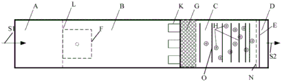
The invention is further described below with reference to the accompanying drawings:
FIG. 1 is a front view of an enhanced ammonia nitrogen treatment MBBR system of a flocculation sedimentation tank of the invention;
FIG. 2 is a top view of an enhanced ammonia nitrogen treatment MBBR system of a flocculation sedimentation tank of the present invention;
in the figure:
A. the device comprises a flocculation reaction zone, a B sedimentation zone, a C aeration reaction zone, a D water outlet zone, an E guide wall, a F sludge collecting hopper, a G first interception screen, a H suspension carrier, an S1 total water inlet pipeline, an S2 total water outlet pipeline, a J sludge passing baffle, a K water outlet weir, an L water distribution tracery wall, an M second interception screen, an N sludge passing channel, an O aeration pipeline, an i1 reaction tank bottom gradient corresponding to the sedimentation zone from the water outlet zone to the sedimentation zone, an i2 aeration reaction zone bottom gradient, a P jet aerator, a Q jet aeration baffle.
Detailed Description
The invention provides a flocculation sedimentation tank enhanced ammonia nitrogen treatment MBBR system and an operation method thereof, and the invention is explained in detail by combining specific embodiments in order to make the advantages and technical scheme of the invention clearer and more clear.
The 'MBBR' referred in the invention refers to moving Bed Biofilm reactor (moving Bed Biofilm reactor), and the method increases the biomass and the biological species in the treatment system by adding a certain amount of suspension carriers into the system and utilizing the Biofilm growing on the suspension carriers to enrich the functional microorganisms, thereby increasing the treatment efficiency of the system.
The 'water distribution wall' mentioned in the invention is provided with a plurality of small holes, and the flocculation reaction zone and the sedimentation zone are communicated through the small holes.
The "flocculation reaction zone" referred to in the present invention is a zone in which solid-liquid separation is carried out by feeding a flocculant thereto.
The term "settling zone" as used herein means the removal of suspended matter from water by the action of gravity.
The filling rate, namely the filling rate of the suspension carrier, namely the ratio of the volume of the suspension carrier to the pool volume of the filling area, is referred to in the invention, and the volume of the suspension carrier is the total volume under natural accumulation; e.g. 100m3Suspending vehicle, filled to 400m3The tank capacity and the filling rate are 25 percent.
The jet aerator is connected with a compressed air pipeline through the connection of the aeration device and a water pump, so that water flow is jetted to generate fine bubbles, air in the bubbles is fully contacted with water, oxygen is dissolved in the water, and the aeration effect is achieved.
Referring to fig. 1 and 2, the flocculation sedimentation tank enhanced ammonia nitrogen treatment MBBR system of the present invention comprises a reaction tank, a total water inlet pipeline S1, a total water outlet pipeline S2, a suspension carrier H and an accessory component.
The reaction tank is sequentially divided into a flocculation reaction zone A, a sedimentation zone B, an aeration reaction zone C and a water outlet zone D from front to back, a total water inlet pipeline S1 is connected to a tank body of the flocculation reaction zone, a total water outlet pipeline S2 is connected to a tank body of the water outlet zone, water to be treated enters from the total water inlet pipeline, sequentially passes through the flocculation reaction zone, the sedimentation zone, the aeration reaction zone and the water outlet zone and then is discharged through the total water outlet pipeline, and ammonia nitrogen, TP, COD and SS in the water to be treated are removed to realize purification; the main water outlet pipeline is positioned at the upper part of the water outlet area, and the central elevation of the main water outlet pipeline is the same as the liquid level in the system.
As a main improvement point of the invention, the bottom of the reaction tank located in the flocculation reaction zone is designed horizontally, the bottom of the reaction tank corresponding to the position from the water outlet zone D to the settling zone B is designed obliquely downwards and forms a slope, the slope is the slope i1 of the bottom of the reaction tank corresponding to the position from the water outlet zone to the settling zone, the range of the slope is 2-5%, the position of the bottom of the reaction tank close to one side of the water outlet zone is higher, the position of the bottom of the reaction tank located in the settling zone is lowest, and the lowest position of the bottom of the reaction tank is provided with a sludge collecting hopper F; the tank bottom at the bottom of the aeration reaction zone is designed in an inclined upward manner from a water outlet end to a water inlet end and forms another gradient, the gradient is the gradient i2 of the tank bottom of the aeration reaction zone, the range of the gradient is 2-5%, and a sludge passage N is arranged between the tank bottom of the aeration reaction zone and the tank bottom of the reaction tank; the position of the bottom of the tank close to the settling zone is low, so that the dropped biological membrane can flow into the sludge collecting hopper of the settling zone through the sludge channel N.
The auxiliary components comprise an effluent weir K, a flow guide wall E, a mud passing baffle J, an aeration pipeline O, an aeration valve, a first interception screen G and a second interception screen M, wherein the effluent weir K is arranged at the upper part of the effluent end of the settling zone, effluent of the effluent weir enters the aeration reaction zone, and the upper edge of the effluent weir is lower than the operating water level; the guide wall E is positioned in the water outlet area D, the upper end of the guide wall is higher than the liquid level in the system to ensure that water cannot pass through, and the vertical distance between the lower end of the guide wall and the bottom of the water outlet area is 1.0-1.5 m.
And the mud passing baffle J is positioned between the mud passing channel and the settling zone, the upper part of the mud passing baffle is connected with the bottom of the aeration reaction zone, the connection point is the front end of the first interception screen, the lower part of the mud passing baffle extends towards the bottom of the settling zone and forms an included angle of 45-60 degrees with the vertical direction, and the horizontal length of the mud passing baffle is not more than that of the effluent weir.
As another improvement point of the invention, jet flow aerators P are arranged in sludge passing channels right below the guide wall and right below the front tank wall of the aeration reaction zone, a jet flow aeration baffle Q is arranged right above each jet flow aerator at a certain interval, and a biomembrane dropped in the water outlet zone enters the sludge passing channels and flows to a sludge collecting hopper along the sludge passing channels. The jet aeration baffle plate positioned right below the front tank wall of the aeration reaction zone is connected with 80-90% of the length of the first interception screen, the jet aeration baffle plate positioned right below the front tank wall of the aeration reaction zone is parallel to the sludge passing baffle plate, and the vertical distance between the jet aerator positioned in the water outlet zone and the corresponding jet aeration baffle plate is kept the same as the vertical distance between the jet aerator positioned in the aeration reaction zone and the corresponding jet aeration baffle plate.
As the main improvement point of the invention, a suspended carrier and an aeration pipeline are arranged in an aeration reaction zone, a first interception screen is arranged at the bottom of the aeration reaction zone, and a biological membrane dropped off in the aeration reaction zone enters a sludge passing channel through the first interception screen arranged at the bottom of the biological membrane and flows to a sludge collecting hopper in the sedimentation zone along the sludge passing channel; preferably, the first interception screen is positioned at the bottom of the water inlet end of the aeration reaction zone, the width of the first interception screen is consistent with that of the aeration reaction zone, and the length of the first interception screen is 15-25% of that of the aeration reaction zone.
The biomembrane that drops in the water outlet zone enters the mud passing channel and flows to the mud collecting hopper along the mud passing channel.
The sludge passage is positioned at the lower part of the aeration reaction zone, is separated from the aeration reaction zone through the bottom of the aeration reaction zone, is communicated with the aeration reaction zone through a first interception screen of the aeration reaction zone, and has the minimum height of not less than 0.5 m.
The aeration pipeline is arranged in a mode of being perpendicular to the water passing direction, is unevenly arranged, is gradually and densely arranged along the water flow direction, and the main pipe and the branch pipe of the aeration pipe are provided with aeration valves.
The second interception screen M is positioned at the upper part of the water outlet end of the aeration reaction zone, and the aeration reaction zone is communicated with the water outlet zone through the second interception screen.
The flocculation reaction area A and the sedimentation area B are communicated through a water distributing wall L.
The operation method of the flocculation sedimentation tank enhanced ammonia nitrogen treatment MBBR modification system is explained in detail below.
The specific operation method is as follows:
firstly, water to be treated enters a flocculation reaction zone from the main water inlet pipeline, passes through a sedimentation zone and then enters an aeration reaction zone;
secondly, in the aeration reaction zone, the concentration of suspended sludge is less than 400mg/L, sludge reflux is not set, and activated sludge is not enriched; the density of the suspension carrier is 0.96-0.98 g/cm3The effective specific surface area is 450-1200 m2/m3The filling rate is 20-60%, and the nitration load of the suspension carrier is 0.1-0.8 gN/m2D; after the sewage to be treated enters the aeration reaction zone, adjusting an aeration valve on a first aeration pipe in the aeration reaction zone to realize intermittent aeration according to the concentration of influent COD, wherein when the influent COD is more than or equal to 500mg/L, the interval time for stopping aeration of the first aeration pipe is 0.5-1.0 h; when the COD of the inlet water is more than or equal to 200 and less than 500mg/L, the interval time of stopping aeration of the first aeration pipe is 1.0-1.5 h; when the COD of the inlet water is more than or equal to 100 and less than 200mg/L, the interval time of stopping aeration of the first aeration pipe is 1.5-2 h; when the COD of the inlet water is less than 100mg/L, the interval time of stopping aeration of the first aeration pipe is 2-2.5 h;
thirdly, the falling biological film respectively enters the bottoms of the sludge passing channel and the water outlet zone through the first interception screen and the bottom of the water outlet zone, a jet aerator is started to accelerate sludge at the bottom of the water outlet end of the sedimentation zone and in the sludge passing channel to move to the bottom of a first sludge collecting hopper in the sedimentation zone, the jet aerator runs intermittently, the aeration flow is consistent with that of a first aeration pipe, the running time is controlled according to the intermittent aeration time of the first aeration pipe, and when the aeration stop interval time of the first aeration pipe is 0.5-1.0 h, the running time of the jet aerator is 5min before the first aeration pipe resumes aeration; when the interval time of the first aeration pipe stopping aeration is 1.0-1.5 h, the running time of the jet aerator is 3min before the first aeration pipe resumes aeration; when the interval time of the first aeration pipe stopping aeration is 1.5-2 h, the running time of the jet aerator is 2min before the first aeration pipe resumes aeration; when the interval time of the first aeration pipe stopping aeration is 2-2.5 h, the running time of the jet aerator is 1min before the first aeration pipe resumes aeration.
The present invention will be described in detail with reference to specific examples.
Example 1:
the designed water quantity of a certain sewage treatment emergency project is 3 ten thousand meters3D, influent COD, NH3The SS design values are respectively 250, 30 and 200mg/L, a flocculation sedimentation tank is adopted to strengthen an ammonia nitrogen treatment MBBR system, a suspension carrier is added into an aeration reaction zone, and the density of the suspension carrier is 0.98g/cm3The effective specific surface area is 800m2/m3The filling rate is 40 percent; the width of the first interception screen at the bottom of the aeration reaction zone is consistent with the width of the bottom of the aeration reaction zone, and the length of the first interception screen is 15 percent of the length of the bottom of the aeration reaction zone; a flow guide wall is arranged in the water area, and the vertical distance between the lower end of the flow guide wall and the bottom of the water outlet area is 1.5 m; a sludge passing baffle is arranged between the sludge passing channel and the sedimentation area, and an included angle of 45 degrees is formed between the sludge passing baffle and the vertical direction; when the system is operated, water to be treated enters the flocculation reaction zone from the main water inlet pipeline, passes through the sedimentation zone and then enters the aeration reaction zone, and an aeration valve on a first aeration pipe in the aeration reaction zone is adjusted to enable the aeration interval time of the first aeration pipe to be 1.5 h; the water treated in the aeration reaction zone passes through the water outlet zone and is discharged by a main water outlet pipeline connected with the water outlet zone, and the residual sludge is discharged by a sludge collecting hopper. After passing through a water outlet zone, yielding water COD and NH3The SS mean values are respectively 11.52, 1.90 and 3.3 mg/L. The falling biological membrane respectively enters the bottom of the sludge passing channel and the bottom of the water outlet zone through the first interception screen and the bottom of the water outlet zone, the jet aerator is started to accelerate the sludge in the bottom of the water outlet zone and the sludge passing channel to move to the bottom of the sludge collecting hopper in the settling zone, the sludge discharge pump is operated intermittently, and the operation time is that the first aeration pipe resumes aerationIn the first 3min, the aeration flow rate is consistent with that of the first aeration pipe. The excess sludge is discharged from a sludge hopper.
Example 2:
the design water quantity of a certain sewage treatment integrated device is 350m3D, influent COD, NH3The SS design values are respectively 150, 20 and 200mg/L, and an efficient flocculation sedimentation tank is adopted to strengthen the ammonia nitrogen treatment MBBR system, wherein a suspension carrier is added into the aeration reaction zone, and the density of the suspension carrier is 0.98g/cm3The effective specific surface area is 800m2/m3The filling rate is 30 percent; the width of the first interception screen at the bottom of the aeration reaction zone is consistent with the width of the bottom of the aeration reaction zone, and the length of the first interception screen is 15 percent of the length of the bottom of the aeration reaction zone; a flow guide wall is arranged in the water area, and the vertical distance between the lower end of the flow guide wall and the bottom of the water outlet area is 1.0 m; a sludge passing baffle is arranged between the sludge passing channel and the sedimentation area, and an included angle of 55 degrees is formed between the sludge passing baffle and the vertical direction; when the system is operated, water to be treated enters the flocculation reaction zone from the main water inlet pipeline, passes through the sedimentation zone and then enters the aeration reaction zone, and an aeration valve on a first aeration pipe in the aeration reaction zone is adjusted to enable the interval time of stopping aeration of the first aeration pipe to be 2 hours; the water treated in the aeration reaction zone passes through the water outlet zone and is discharged by a main water outlet pipeline connected with the water outlet zone, and the effluent COD and NH pass through the water outlet zone3The SS mean values are respectively 38.25, 0.86 and 7.98 mg/L.
And the falling biological film respectively enters the bottoms of the sludge passing channel and the water outlet zone through the first interception screen and the bottom of the water outlet zone, the jet aerator is started to accelerate the sludge in the water outlet zone and the sludge passing channel to move to the bottom of the sludge collecting hopper in the settling zone, the jet aerator is operated intermittently, the operation time is 2min before the first aeration pipe resumes aeration, and the aeration flow is consistent with that of the first aeration pipe. The excess sludge is discharged from a sludge hopper.
The parts which are not described in the invention can be realized by taking the prior art as reference.
It should be noted that: any equivalents or obvious modifications thereof which may occur to persons skilled in the art and which are given the benefit of this description are deemed to be within the scope of the invention.
Claims (9)
1. A flocculation sedimentation tank enhanced ammonia nitrogen treatment MBBR system comprises a reaction tank, a main water inlet pipeline and a main water outlet pipeline, wherein the reaction tank is sequentially divided into a flocculation reaction zone, a sedimentation zone, an aeration reaction zone and a water outlet zone from front to back; the method is characterized in that:
the bottom of the reaction tank positioned in the flocculation reaction zone is designed horizontally, the bottom of the reaction tank corresponding to the position from the water outlet zone to the settling zone is designed obliquely downwards to form a slope, the range of the slope is 2-5%, the bottom of the reaction tank positioned in the settling zone is the lowest, and a sludge collecting hopper is arranged at the lowest position of the bottom of the reaction tank; the bottom of the aeration reaction zone is designed in an inclined upward manner from a water outlet end to a water inlet end and forms another gradient, the range of the another gradient is 2-5%, and a sludge passage is arranged between the bottom of the aeration reaction zone and the bottom of the reaction tank;
a suspended carrier and an aeration pipeline are arranged in the aeration reaction zone, a first interception screen is arranged at the bottom of the aeration reaction zone, and a biological membrane dropped off in the aeration reaction zone enters the sludge passing channel through the first interception screen arranged at the bottom of the water inlet end of the biological membrane and flows to a sludge collecting hopper in the sedimentation zone along the sludge passing channel;
and a guide wall is arranged in the water outlet area, jet aerators are arranged in the sludge passing channels under the guide wall and the front tank wall of the aeration reaction area, a jet aeration baffle is arranged above each jet aerator at a certain interval, and a biofilm dropped in the water outlet area enters the sludge passing channels and flows to the sludge collecting hopper along the sludge passing channels.
2. The MBBR system for the enhanced ammonia nitrogen treatment of the flocculation sedimentation tank as claimed in claim 1, which is characterized in that: the main water inlet pipeline is connected to the tank body on the upper part of the flocculation reaction zone, the main water outlet pipeline is connected to the tank body on the upper part of the water outlet zone, and the flocculation reaction zone is communicated with the sedimentation zone through a water distribution tracery wall.
3. The MBBR system for the enhanced ammonia nitrogen treatment of the flocculation sedimentation tank as claimed in claim 1, which is characterized in that: and the upper part of the water outlet end of the settling zone is provided with a water outlet weir, the upper edge of the water outlet weir is lower than the operating water level, and water flows out of the water outlet weir and enters the aeration reaction zone.
4. The MBBR system for the enhanced ammonia nitrogen treatment of the flocculation sedimentation tank as claimed in claim 1, which is characterized in that:
a second interception screen is arranged between the aeration reaction zone and the water outlet zone and is communicated with the aeration reaction zone through the second interception screen; the aeration pipeline is provided with a plurality of aeration valves which are arranged in an uneven mode and are gradually and densely arranged along the water flow direction.
5. The MBBR system for the enhanced ammonia nitrogen treatment of the flocculation sedimentation tank as claimed in claim 1, which is characterized in that: the width of the first interception screen is consistent with that of the bottom of the aeration reaction zone, and the length of the first interception screen is 15-25% of that of the bottom of the aeration reaction zone.
6. The MBBR system for the enhanced ammonia nitrogen treatment of the flocculation sedimentation tank as claimed in claim 1, which is characterized in that: the upper end of water conservancy diversion wall be higher than liquid level in the system, the perpendicular distance of the bottom of the pool of its lower extreme and effluent zone be 1.0 ~ 1.5m, cross and be provided with the mud baffle between mud passageway and the settling zone, cross mud baffle upper portion and connect the front end of first interception screen cloth, the lower part to the settling zone extend, cross mud baffle and vertical direction be 45 ~ 60 contained angles, the horizontal length of crossing the mud baffle be less than the horizontal length of play weir.
7. The MBBR system for the enhanced ammonia nitrogen treatment of the flocculation sedimentation tank as claimed in claim 1, which is characterized in that: the jet aeration baffle plate positioned right below the front tank wall of the aeration reaction zone is connected with 80-90% of the length of the first interception screen, the jet aeration baffle plate positioned right below the front tank wall of the aeration reaction zone is parallel to the sludge passing baffle plate, and the vertical distance between the jet aerator positioned in the water outlet zone and the corresponding jet aeration baffle plate is kept the same as the vertical distance between the jet aerator positioned in the aeration reaction zone and the corresponding jet aeration baffle plate.
8. The MBBR system for the enhanced ammonia nitrogen treatment of the flocculation sedimentation tank as claimed in claim 1, which is characterized in that: the minimum height of the mud passing channel is not lower than 0.5 m.
9. The operation method of the flocculation sedimentation tank MBBR (ammonia nitrogen reduction) system for strengthening ammonia nitrogen treatment according to any one of claims 1 to 8, which is characterized by sequentially comprising the following steps:
s1, enabling the water to be treated to enter a flocculation reaction zone from the main water inlet pipeline, and enabling the water to pass through a sedimentation zone and then enter an aeration reaction zone;
s2, in the aeration reaction zone, the concentration of suspended sludge is less than 400mg/L, no sludge reflux is set, and no activated sludge is enriched; the density of the suspension carrier is 0.96-0.98 g/cm3The effective specific surface area is 450-1200 m2/m3The filling rate is 20-60%, and the nitration load of the suspension carrier is 0.1-0.8 gN/m2D; after the sewage to be treated enters the aeration reaction zone, adjusting an aeration valve on a first aeration pipe in the aeration reaction zone to realize intermittent aeration according to the concentration of influent COD, wherein when the influent COD is more than or equal to 500mg/L, the interval time for stopping aeration of the first aeration pipe is 0.5-1.0 h; when the COD of the inlet water is more than or equal to 200 and less than 500mg/L, the interval time of stopping aeration of the first aeration pipe is 1.0-1.5 h; when the COD of the inlet water is more than or equal to 100 and less than 200mg/L, the first aeration is carried outThe interval time of stopping aeration of the air pipe is 1.5-2 h; when the COD of the inlet water is less than 100mg/L, the interval time of stopping aeration of the first aeration pipe is 2-2.5 h;
s3, enabling the falling biological film to enter the bottoms of the sludge passing channel and the water outlet zone through the first intercepting screen and the bottom of the water outlet zone respectively, starting a jet aerator to accelerate sludge in the bottom of the water outlet end of the sedimentation zone and the sludge passing channel to move to the bottom of a first sludge collecting hopper in the sedimentation zone, wherein the jet aerator runs intermittently, the aeration flow is consistent with that of a first aeration pipe, the running time is controlled according to the intermittent aeration time of the first aeration pipe, and when the aeration stop interval time of the first aeration pipe is 0.5-1.0 h, the running time of the jet aerator is 5min before the first aeration pipe resumes aeration; when the interval time of the first aeration pipe stopping aeration is 1.0-1.5 h, the running time of the jet aerator is 3min before the first aeration pipe resumes aeration; when the interval time of the first aeration pipe stopping aeration is 1.5-2 h, the running time of the jet aerator is 2min before the first aeration pipe resumes aeration; when the interval time of the first aeration pipe stopping aeration is 2-2.5 h, the running time of the jet aerator is 1min before the first aeration pipe resumes aeration.
Priority Applications (1)
| Application Number | Priority Date | Filing Date | Title |
|---|---|---|---|
| CN202011522655.7A CN112551822B (en) | 2020-12-22 | 2020-12-22 | MBBR (moving bed biofilm reactor) system for enhanced ammonia nitrogen treatment of flocculation sedimentation tank and operation method |
Applications Claiming Priority (1)
| Application Number | Priority Date | Filing Date | Title |
|---|---|---|---|
| CN202011522655.7A CN112551822B (en) | 2020-12-22 | 2020-12-22 | MBBR (moving bed biofilm reactor) system for enhanced ammonia nitrogen treatment of flocculation sedimentation tank and operation method |
Publications (2)
| Publication Number | Publication Date |
|---|---|
| CN112551822A true CN112551822A (en) | 2021-03-26 |
| CN112551822B CN112551822B (en) | 2023-11-24 |
Family
ID=75032092
Family Applications (1)
| Application Number | Title | Priority Date | Filing Date |
|---|---|---|---|
| CN202011522655.7A Active CN112551822B (en) | 2020-12-22 | 2020-12-22 | MBBR (moving bed biofilm reactor) system for enhanced ammonia nitrogen treatment of flocculation sedimentation tank and operation method |
Country Status (1)
| Country | Link |
|---|---|
| CN (1) | CN112551822B (en) |
Citations (5)
| Publication number | Priority date | Publication date | Assignee | Title |
|---|---|---|---|---|
| SU931719A1 (en) * | 1977-11-02 | 1982-05-30 | Ордена Трудового Красного Знамени Институт Химии Древесины Ан Латвсср | Apparatus for biochemically purifying effluents |
| KR20090027077A (en) * | 2007-09-11 | 2009-03-16 | 주식회사 에코다임 | Horizontal sedimentation system |
| CN106110717A (en) * | 2016-08-10 | 2016-11-16 | 云南驰宏锌锗股份有限公司 | A kind of ore dressing water treatment system with regulation and impurity sedimentation concentration one |
| CN108585385A (en) * | 2018-06-29 | 2018-09-28 | 青岛思普润水处理股份有限公司 | A kind of MBBR sewage disposal systems and treatment process |
| CN214400158U (en) * | 2020-12-22 | 2021-10-15 | 青岛思普润水处理股份有限公司 | Flocculation and precipitation pond intensification ammonia nitrogen treatment MBBR system |
-
2020
- 2020-12-22 CN CN202011522655.7A patent/CN112551822B/en active Active
Patent Citations (5)
| Publication number | Priority date | Publication date | Assignee | Title |
|---|---|---|---|---|
| SU931719A1 (en) * | 1977-11-02 | 1982-05-30 | Ордена Трудового Красного Знамени Институт Химии Древесины Ан Латвсср | Apparatus for biochemically purifying effluents |
| KR20090027077A (en) * | 2007-09-11 | 2009-03-16 | 주식회사 에코다임 | Horizontal sedimentation system |
| CN106110717A (en) * | 2016-08-10 | 2016-11-16 | 云南驰宏锌锗股份有限公司 | A kind of ore dressing water treatment system with regulation and impurity sedimentation concentration one |
| CN108585385A (en) * | 2018-06-29 | 2018-09-28 | 青岛思普润水处理股份有限公司 | A kind of MBBR sewage disposal systems and treatment process |
| CN214400158U (en) * | 2020-12-22 | 2021-10-15 | 青岛思普润水处理股份有限公司 | Flocculation and precipitation pond intensification ammonia nitrogen treatment MBBR system |
Also Published As
| Publication number | Publication date |
|---|---|
| CN112551822B (en) | 2023-11-24 |
Similar Documents
| Publication | Publication Date | Title |
|---|---|---|
| CN109879425B (en) | Equipment for advanced phosphorus and nitrogen removal of sewage treatment | |
| CN106927638B (en) | Multistage diversion type MBBR sewage treatment system and treatment method | |
| KR100741019B1 (en) | Water treatment device and method by using a combination of wetland and contact oxidation filtration facilities | |
| CN106745749B (en) | Aerobic-anoxic integrated AO membrane bioreactor | |
| CN111704323A (en) | High-efficient sewage treatment system of modularization integrated form | |
| KR101963370B1 (en) | SBR with improved MLSS precipitation efficiency | |
| CN111875182A (en) | Micro-polluted water treatment system | |
| CN214400158U (en) | Flocculation and precipitation pond intensification ammonia nitrogen treatment MBBR system | |
| CN212655653U (en) | Anti-blocking and enhanced anaerobic ammonia oxidation and denitrification constructed wetland system | |
| CN213171940U (en) | High-efficient sewage treatment system of modularization integrated form | |
| CN114014492A (en) | Low carbon nitrogen ratio sewage treatment system | |
| CN212713126U (en) | Integration MBR membrane sewage treatment device | |
| CN214299758U (en) | High-efficient flocculation and precipitation pond intensification ammonia nitrogen handles MBBR system | |
| CN112537887B (en) | MBBR (moving bed biofilm reactor) system for strengthening ammonia nitrogen treatment of high-efficiency flocculation sedimentation tank and operation method | |
| CN214457483U (en) | Sewage treatment system with flocculation precipitation coupled with MBBR (moving bed biofilm reactor) | |
| CN112551826B (en) | Sewage treatment system with flocculation precipitation coupled MBBR and operation method | |
| CN102381809B (en) | Coal mine domestic wastewater treatment device and treatment method | |
| CN210438573U (en) | Stifled oxygenation type constructed wetland system of inhibiting | |
| CN205347124U (en) | City river drain sewage treatment device | |
| CN112551822B (en) | MBBR (moving bed biofilm reactor) system for enhanced ammonia nitrogen treatment of flocculation sedimentation tank and operation method | |
| CN202226752U (en) | Treating equipment for domestic sewage of coal mine | |
| CN103102041B (en) | A kind of supernatant superimposed bio-contact oxidation combination pond and treatment process thereof | |
| CN213141749U (en) | Pretreatment tank and water body treatment system using same | |
| CN107381817A (en) | A kind of micro- oxygen denitrification reactor of cavitation-preventive | |
| CN113754179A (en) | Anti-blocking and anaerobic ammonia oxidation and denitrification enhancing constructed wetland system and technology |
Legal Events
| Date | Code | Title | Description |
|---|---|---|---|
| PB01 | Publication | ||
| PB01 | Publication | ||
| SE01 | Entry into force of request for substantive examination | ||
| SE01 | Entry into force of request for substantive examination | ||
| GR01 | Patent grant | ||
| GR01 | Patent grant |