CN112545486A - Medical image diagnosis apparatus and magnetic resonance imaging apparatus - Google Patents
Medical image diagnosis apparatus and magnetic resonance imaging apparatus Download PDFInfo
- Publication number
- CN112545486A CN112545486A CN202011398851.8A CN202011398851A CN112545486A CN 112545486 A CN112545486 A CN 112545486A CN 202011398851 A CN202011398851 A CN 202011398851A CN 112545486 A CN112545486 A CN 112545486A
- Authority
- CN
- China
- Prior art keywords
- top plate
- movable body
- patient
- screen
- bed
- Prior art date
- Legal status (The legal status is an assumption and is not a legal conclusion. Google has not performed a legal analysis and makes no representation as to the accuracy of the status listed.)
- Pending
Links
Images


Classifications
-
- A—HUMAN NECESSITIES
- A61—MEDICAL OR VETERINARY SCIENCE; HYGIENE
- A61B—DIAGNOSIS; SURGERY; IDENTIFICATION
- A61B5/00—Measuring for diagnostic purposes; Identification of persons
- A61B5/05—Detecting, measuring or recording for diagnosis by means of electric currents or magnetic fields; Measuring using microwaves or radio waves
- A61B5/055—Detecting, measuring or recording for diagnosis by means of electric currents or magnetic fields; Measuring using microwaves or radio waves involving electronic [EMR] or nuclear [NMR] magnetic resonance, e.g. magnetic resonance imaging
-
- A—HUMAN NECESSITIES
- A61—MEDICAL OR VETERINARY SCIENCE; HYGIENE
- A61B—DIAGNOSIS; SURGERY; IDENTIFICATION
- A61B5/00—Measuring for diagnostic purposes; Identification of persons
- A61B5/74—Details of notification to user or communication with user or patient ; user input means
- A61B5/742—Details of notification to user or communication with user or patient ; user input means using visual displays
- A61B5/7445—Display arrangements, e.g. multiple display units
-
- A—HUMAN NECESSITIES
- A61—MEDICAL OR VETERINARY SCIENCE; HYGIENE
- A61B—DIAGNOSIS; SURGERY; IDENTIFICATION
- A61B5/00—Measuring for diagnostic purposes; Identification of persons
- A61B5/103—Detecting, measuring or recording devices for testing the shape, pattern, colour, size or movement of the body or parts thereof, for diagnostic purposes
- A61B5/11—Measuring movement of the entire body or parts thereof, e.g. head or hand tremor, mobility of a limb
-
- A—HUMAN NECESSITIES
- A61—MEDICAL OR VETERINARY SCIENCE; HYGIENE
- A61B—DIAGNOSIS; SURGERY; IDENTIFICATION
- A61B5/00—Measuring for diagnostic purposes; Identification of persons
- A61B5/70—Means for positioning the patient in relation to the detecting, measuring or recording means
- A61B5/704—Tables
-
- A—HUMAN NECESSITIES
- A61—MEDICAL OR VETERINARY SCIENCE; HYGIENE
- A61B—DIAGNOSIS; SURGERY; IDENTIFICATION
- A61B5/00—Measuring for diagnostic purposes; Identification of persons
- A61B5/72—Signal processing specially adapted for physiological signals or for diagnostic purposes
-
- A—HUMAN NECESSITIES
- A61—MEDICAL OR VETERINARY SCIENCE; HYGIENE
- A61B—DIAGNOSIS; SURGERY; IDENTIFICATION
- A61B5/00—Measuring for diagnostic purposes; Identification of persons
- A61B5/74—Details of notification to user or communication with user or patient ; user input means
- A61B5/7405—Details of notification to user or communication with user or patient ; user input means using sound
-
- A—HUMAN NECESSITIES
- A61—MEDICAL OR VETERINARY SCIENCE; HYGIENE
- A61M—DEVICES FOR INTRODUCING MEDIA INTO, OR ONTO, THE BODY; DEVICES FOR TRANSDUCING BODY MEDIA OR FOR TAKING MEDIA FROM THE BODY; DEVICES FOR PRODUCING OR ENDING SLEEP OR STUPOR
- A61M21/00—Other devices or methods to cause a change in the state of consciousness; Devices for producing or ending sleep by mechanical, optical, or acoustical means, e.g. for hypnosis
- A61M21/02—Other devices or methods to cause a change in the state of consciousness; Devices for producing or ending sleep by mechanical, optical, or acoustical means, e.g. for hypnosis for inducing sleep or relaxation, e.g. by direct nerve stimulation, hypnosis, analgesia
-
- A—HUMAN NECESSITIES
- A61—MEDICAL OR VETERINARY SCIENCE; HYGIENE
- A61B—DIAGNOSIS; SURGERY; IDENTIFICATION
- A61B5/00—Measuring for diagnostic purposes; Identification of persons
- A61B5/0033—Features or image-related aspects of imaging apparatus classified in A61B5/00, e.g. for MRI, optical tomography or impedance tomography apparatus; arrangements of imaging apparatus in a room
- A61B5/004—Features or image-related aspects of imaging apparatus classified in A61B5/00, e.g. for MRI, optical tomography or impedance tomography apparatus; arrangements of imaging apparatus in a room adapted for image acquisition of a particular organ or body part
- A61B5/0042—Features or image-related aspects of imaging apparatus classified in A61B5/00, e.g. for MRI, optical tomography or impedance tomography apparatus; arrangements of imaging apparatus in a room adapted for image acquisition of a particular organ or body part for the brain
-
- A—HUMAN NECESSITIES
- A61—MEDICAL OR VETERINARY SCIENCE; HYGIENE
- A61M—DEVICES FOR INTRODUCING MEDIA INTO, OR ONTO, THE BODY; DEVICES FOR TRANSDUCING BODY MEDIA OR FOR TAKING MEDIA FROM THE BODY; DEVICES FOR PRODUCING OR ENDING SLEEP OR STUPOR
- A61M21/00—Other devices or methods to cause a change in the state of consciousness; Devices for producing or ending sleep by mechanical, optical, or acoustical means, e.g. for hypnosis
- A61M2021/0005—Other devices or methods to cause a change in the state of consciousness; Devices for producing or ending sleep by mechanical, optical, or acoustical means, e.g. for hypnosis by the use of a particular sense, or stimulus
- A61M2021/0044—Other devices or methods to cause a change in the state of consciousness; Devices for producing or ending sleep by mechanical, optical, or acoustical means, e.g. for hypnosis by the use of a particular sense, or stimulus by the sight sense
- A61M2021/005—Other devices or methods to cause a change in the state of consciousness; Devices for producing or ending sleep by mechanical, optical, or acoustical means, e.g. for hypnosis by the use of a particular sense, or stimulus by the sight sense images, e.g. video
-
- A—HUMAN NECESSITIES
- A61—MEDICAL OR VETERINARY SCIENCE; HYGIENE
- A61M—DEVICES FOR INTRODUCING MEDIA INTO, OR ONTO, THE BODY; DEVICES FOR TRANSDUCING BODY MEDIA OR FOR TAKING MEDIA FROM THE BODY; DEVICES FOR PRODUCING OR ENDING SLEEP OR STUPOR
- A61M2205/00—General characteristics of the apparatus
- A61M2205/50—General characteristics of the apparatus with microprocessors or computers
- A61M2205/502—User interfaces, e.g. screens or keyboards
- A61M2205/507—Head Mounted Displays [HMD]
Abstract
The invention provides a medical image diagnosis apparatus and a magnetic resonance imaging apparatus, which improve the habitability in a cavity hole of a stand. The stand is formed with a cavity hole and is equipped with a medical imaging mechanism. The couch moves the top plate along the central axis of the bore. The moving body and the top plate are provided separately and movably along the central axis of the cavity. The screen is provided on the moving object and projects an image from the projector. The reflection plate reflects the image projected to the screen. The support body is provided on the movable body and supports the reflection plate.
Description
The present application is a divisional application having an application number of 201610969212.X, an application date of 2016, 10, and 28, entitled "medical image diagnosis apparatus and magnetic resonance imaging apparatus".
This application is based on Japanese patent application No. 2015-214741 filed on 30/10/2015, to which priority is given. This application incorporates by reference the entire contents of that application.
Technical Field
Embodiments of the present invention relate to a medical image diagnostic apparatus and a magnetic resonance imaging apparatus.
Background
The magnetic resonance imaging apparatus has a gantry on which an imaging mechanism such as a magnet is mounted. A cavity hole having a substantially hollow shape is formed in the mount. MR (Magnetic Resonance) imaging is performed with the patient inserted into the bore. Although a gantry having a relatively large bore diameter has been developed, many patients feel stress in MR examination due to long MR imaging time, noise in driving the gantry, and a feeling of pressure and occlusion in the bore.
Patent document 1: japanese laid-open patent publication No. 2001-314391
Disclosure of Invention
An object of an embodiment is to provide a medical image diagnostic apparatus and a magnetic resonance imaging apparatus that can improve the habitability in a cavity of a gantry.
The present invention is a medical image diagnostic apparatus including: a stand having a cavity hole and equipped with a medical camera mechanism; a bed for moving a top plate on which a subject is placed; a moving body provided separately from the top plate and movable along a center axis of the cavity in association with the top plate; a screen provided on the movable body; a reflecting plate for reflecting the image of the screen toward the subject; a support body provided on the movable body and supporting the reflection plate; and a coupling portion that couples the movable body and the top plate, and that couples and decouples the coupling portion when the movable body is positioned in the cavity.
ADVANTAGEOUS EFFECTS OF INVENTION
The habitability in the cavity of the stand can be improved.
Drawings
Fig. 1 is a diagram showing a configuration of a medical image diagnostic system including a medical image diagnostic apparatus according to the present embodiment.
Fig. 2 is a diagram showing a configuration of a magnetic resonance imaging apparatus according to the present embodiment.
Fig. 3 is a diagram showing an example of an installation environment of the magnetic resonance imaging system according to the present embodiment.
Fig. 4 is a perspective view of the gantry housing of the present embodiment.
Fig. 5 is a perspective view of the mobile screen device of the present embodiment.
Fig. 6 is a side view of the mobile screen apparatus of fig. 5.
Fig. 7 is a front view of the mobile screen device of fig. 5.
Fig. 8 is a perspective view of the mobile screen device and the top plate connected to each other according to the present embodiment.
Fig. 9 is a schematic front view of the screen of the present embodiment disposed within the bore.
Fig. 10 is a side view of the mobile screen device of fig. 6 with the support arm sliding in the Z-axis.
Fig. 11 is a simplified side view of the mobile screen device of the present embodiment disposed in the cavity of the stand.
Fig. 12 is a simplified side view of the mobile screen device and the top plate according to the present embodiment.
Fig. 13 is a diagram showing the connection between the portable screen device and the top plate according to the present embodiment.
Fig. 14 is a diagram showing the release of the connection between the portable screen device and the top panel according to the present embodiment.
Fig. 15 is a diagram showing a typical flow of an MR examination using the magnetic resonance imaging system according to the present embodiment.
Fig. 16 is a diagram showing the mobile screen device according to the 1 st projection mode of the present embodiment from the side of the stand.
Fig. 17 is a view showing the mobile screen device according to the 1 st projection mode of the present embodiment from the front of the stand.
Fig. 18 is a diagram showing the mobile screen device of the 2 nd projection mode of the present embodiment from the side of the stand.
Fig. 19 is a diagram schematically showing the portable screen device of application example 1.
Fig. 20 is a diagram schematically showing a portable screen device according to application example 2.
Fig. 21 is a side view of the mobile screen apparatus of application example 3.
Fig. 22 is a side view of the entire mobile screen device and stand of application example 3.
Fig. 23 is a diagram showing a mobile screen device in which an optical camera of application example 3 is attached to a support arm.
Fig. 24 is a diagram showing a mobile screen device in which the optical camera of application example 3 is mounted on a screen.
Fig. 25 is a side view of the mobile screen apparatus of application example 5.
Fig. 26 is a side view of the mobile screen device and the stand of application example 5 as a whole.
Fig. 27 is a side view of the mobile screen apparatus of application example 6.
Fig. 28 is a view showing an XZ cross section (horizontal cross section) of the support arm according to the present embodiment.
Fig. 29 is a view showing an XZ cross section (horizontal cross section) of the support arm of application example 8.
Description of the symbols
1: medical image diagnostic systems (magnetic resonance imaging systems); 10: a medical image diagnostic apparatus (magnetic resonance imaging apparatus); 11: a stand; 13: a diagnostic bed; 15: a mobile screen device; 17: an image pickup control unit; 21: a gradient magnetic field power supply; 23: a transmission circuit; 25: a receiving circuit; 27: a console; 31: a camera control circuit; 32: a reconstruction circuit; 33: an image processing circuit; 34: a communication circuit; 35: a display circuit; 36: an input circuit; 37: a main memory circuit; 38: a system control circuit; 41: a static magnetic field magnet; 43: a gradient magnetic field coil; 45: an RF coil; 51: a stand frame; 53: a bore; 55: a guide rail; 57: an inner wall; 61: moving the trolley; 63: a screen; 65: a support arm; 65': a support arm; 67: a reflective plate; 69: a coupling projection (hook); 71: a sliding mechanism; 73: a link mechanism; 75: a link mechanism; 80: an optical camera; 81: an objective lens; 83: an optical fiber; 91: a microphone; 93: a cable; 95: an amplifier; 97: a speaker; 100: a projector; 131: a top plate; 133: a base station; 135: a bed driving device; 137: a patient securing device; 139: a connecting recess (groove); 200: a projector control device; 300: an examination room; 400: a control room; 500: a wall; 510: a window; 610: an end face; 611: a guide; 651: a wheel; 653: a 1 st arm; 655: a 2 nd arm; d1: a door; d2: a door; d3: a door; g1: a gap; PE 1: the side end part of the diagnostic bed; RI 1: an inner space; RR 1: a rotating shaft; RR 2: a rotating shaft; RR 3: a rotating shaft; RR 4: and (4) rotating the shaft.
Detailed Description
The medical image diagnostic apparatus according to the present embodiment includes a gantry, a bed, a movable body, a screen, a reflecting plate, and a support. The stand is provided with a cavity hole and is provided with a medical camera shooting mechanism. The couch moves the top plate along the central axis of the bore. The moving body is provided separately from the top plate and is provided so as to be movable along the central axis of the cavity. The screen is provided on the moving object and projects an image from the projector. The reflecting plate reflects the image projected to the screen. The support body is provided on the movable body and supports the reflection plate.
As a technique for reducing the stress in the MR examination, the following technique can be considered. For example, there are: 1. a goggle type head mounted display; 2. arranging a liquid crystal display on the ceiling and the wall of the inspection room; 3. a head coil mounted with a mirror for observing the image of the liquid crystal display disposed behind the stand. However, in the case of the technique 1, since the head mount display is attached to the head of the patient, a feeling of pressure and a feeling of occlusion are given to the patient. In the case of the technique of 2, when the patient enters the gantry, the image of the liquid crystal display cannot be viewed. In the case of the technique of 3, since an image can be viewed through a mirror attached to the head coil in MR imaging, the sense of occlusion due to the bore can be reduced. However, a mirror must be mounted for each head coil. Further, since the mirror is attached to the gap between the head coils covering the head, the patient hardly receives the spread of the image. Further, since the liquid crystal display is provided behind the gantry without a device that blocks the front of the gantry, the patient can easily visually confirm the cavity when the patient is outside the gantry before MR imaging, and thereafter, even if, for example, the patient mounts the head coil and views an image via a mirror, the patient cannot feel that the patient is in the cavity. Further, since the positional relationship between the mirror and the liquid crystal display changes with the movement of the top plate, the patient feels as if he or she were moving in the cavity even if he or she views the image of the liquid crystal display through the mirror while the top plate is moving.
The medical image diagnostic apparatus and the magnetic resonance imaging apparatus according to the present embodiment will be described below with reference to the drawings.
Fig. 1 is a diagram showing a configuration of a medical image diagnostic system 1 including a medical image diagnostic apparatus 10 according to the present embodiment. As shown in fig. 1, a medical image diagnostic system 1 includes: the medical image diagnostic apparatus 10, the projector 100, and the projector control apparatus 200 are connected to each other so as to be able to communicate with each other by wire or wirelessly. The medical image diagnostic apparatus 10 includes a gantry 11, a bed 13, a mobile screen device 15, and an imaging control unit 17. For example, the gantry 11, the bed 13, and the mobile screen device 15 are provided in an examination room, and the imaging control unit 17 is provided in a control room adjacent to the examination room. The gantry 11 is equipped with a mechanism for realizing medical imaging. A cavity having a hollow shape is formed in the mount 11. A bed 13 is provided in front of the gantry 11. The bed 13 movably supports a top plate on which the patient P is placed. The bed 13 moves the top plate under the control of the gantry 11, the console, and the like. A movable screen device 15 is movably disposed in the cavity of the stand 11. A projector 100 is provided in front of or behind the gantry 11. The image from the projector 100 is projected onto the mobile screen device 15.
The projector control device 200 is a computer device that controls the projector 100. The projector control device 200 supplies data relating to the image to be projected to the projector 100. The projector 100 projects an image corresponding to the data from the projector control device 200 onto the screen of the mobile screen device 15. As the projector 100, for example, a Liquid Crystal system, a DLP (Digital Light Processing) system, an LCOS (Liquid Crystal On Silicon) system, a GLV (Grating Light Valve) system, and the like can be used. In this case, the projector 100 mounts at least a display device and a light source. The display device displays an image corresponding to the data from the projector control apparatus 200. The light source irradiates light directly or indirectly via an optical system toward the display device. Light transmitted or reflected from the display device (hereinafter, referred to as projection light) is emitted to the outside of the projector 100 directly or indirectly via an optical system. By irradiating the projection light toward the mobile screen device 15, an image corresponding to the projection light is projected on the mobile screen device 15.
The imaging control unit 17 functions as a center of the medical image diagnostic apparatus 10. For example, the imaging control unit 17 controls the gantry 11 to perform medical imaging. The imaging control unit 17 reconstructs a medical image relating to the patient P based on the raw data collected by the gantry 11 during medical imaging. The imaging control unit 17 may be configured to control the projector 100 via the projector control device 200. The imaging control unit 17 may supply data relating to the image to be projected to the projector 100. In this case, the projector 100 projects an image corresponding to the data from the imaging control unit 17 onto the screen of the mobile screen device 15.
The configuration of the medical image diagnostic system 1 according to the present embodiment is not limited to the above configuration. For example, if the imaging control unit 17 has a function of controlling the projector 100 by the projector control device 200, the projector control device 200 does not need to be installed in the medical image diagnosis system 1.
The medical image diagnostic system 1 according to the present embodiment can improve the habitability of the medical image diagnostic apparatus 10 in the cavity when the medical imaging is performed by using the projector 100 and the portable screen device 15. The medical image diagnostic apparatus 10 according to the present embodiment may be any apparatus that can image the patient P using the gantry 11 in which the bore is formed. Specifically, the medical image diagnostic apparatus 10 of the present embodiment can be applied to a Single system such as a Magnetic Resonance Imaging (MRI) apparatus, a Computed Tomography (CT) apparatus, a PET (Positron Emission Tomography) apparatus, and a SPECT (Single Photon Emission Computed Tomography) apparatus. Alternatively, the medical image diagnostic apparatus 10 according to the present embodiment may be applied to a composite system such as an MR/PET apparatus, a CT/PET apparatus, an MR/SPECT apparatus, and a CT/SPECT apparatus. However, for the purpose of specifically describing the following, the medical image diagnostic apparatus 10 of the present embodiment is referred to as a magnetic resonance imaging apparatus 10. The medical image diagnosis system 1 including the magnetic resonance imaging apparatus 10, the projector 100, and the projector control apparatus 200 is referred to as a magnetic resonance imaging system 1.
Fig. 2 is a diagram showing the configuration of the magnetic resonance imaging apparatus 10 according to the present embodiment. As shown in fig. 2, the magnetic resonance imaging apparatus 10 includes an imaging control unit 17, a gantry 11, a bed 13, and a mobile screen device 15. The imaging control unit 17 includes a gradient magnetic field power supply 21, a transmission circuit 23, a reception circuit 25, and a console 27. The console 27 includes an imaging control circuit 31, a reconstruction circuit 32, an image processing circuit 33, a communication circuit 34, a display circuit 35, an input circuit 36, a main memory circuit 37, and a system control circuit 38. The imaging control circuit 31, the reconstruction circuit 32, the image processing circuit 33, the communication circuit 34, the display circuit 35, the input circuit 36, the main memory circuit 37, and the system control circuit 38 are communicably connected to each other via a bus. The gradient magnetic field power supply 21, the transmission circuit 23, and the reception circuit 25 are provided separately from the console 27 and the gantry 11.
The gantry 11 includes a static field magnet 41, a gradient coil 43, and an RF coil 45. The static field magnet 41 and the gradient coil 43 are housed in a housing (hereinafter, referred to as a gantry housing) 51 of the gantry 11. A cavity 53 having a hollow shape is formed in the gantry frame 51. The RF coil 45 is disposed in the cavity hole 53 of the gantry housing 51. The mobile screen device 15 according to the present embodiment is disposed in the cavity hole 53 of the gantry housing 51.
The static field magnet 41 has a hollow substantially cylindrical shape, and generates a static magnetic field inside the substantially cylindrical shape. As the static field magnet 41, for example, a permanent magnet, a superconducting magnet, a normal conducting magnet, or the like is used. Here, the central axis of the static field magnet 41 is defined as a Z axis, an axis perpendicular to the Z axis is referred to as a Y axis, and an axis perpendicular to the Z axis is referred to as an X axis. The X-axis, Y-axis and Z-axis form an orthogonal three-dimensional coordinate system.
The gradient coil 43 is a coil unit that is mounted inside the static field magnet 41 and is formed in a hollow substantially cylindrical shape. The gradient coil 43 generates a gradient magnetic field by receiving a current supply from the gradient magnetic field power supply 21.
The gradient magnetic field power supply 21 supplies a current to the gradient magnetic field coil 43 in accordance with the control performed by the imaging control circuit 31. The gradient magnetic field power supply 21 supplies a current to the gradient magnetic field coil 43, thereby causing the gradient magnetic field coil 43 to generate a gradient magnetic field.
The RF coil 45 is disposed inside the gradient coil 43, and generates a radio frequency magnetic field upon receiving the RF pulse from the transmission circuit 23. The RF coil 45 receives a magnetic resonance signal (hereinafter, referred to as an MR signal) emitted from the target nuclei present in the patient P by the action of the radio-frequency magnetic field. The received MR signals are supplied to the receiving circuit 25 via wire or wirelessly. The RF coil 45 has a transmitting/receiving function, but a transmitting RF coil and a receiving RF coil may be provided separately.
The transmission circuit 23 transmits a high-frequency magnetic field for exciting the nuclei of the subject existing in the patient P to the patient P via the RF coil 45. As the target nucleus, a proton is typically used. Specifically, the transmission circuit 23 supplies a high-frequency signal (RF signal) for exciting the target nucleus to the RF coil 45 in accordance with the control of the imaging control circuit 31. The high-frequency magnetic field generated from the RF coil 45 vibrates the object nuclei at the natural resonance frequency to excite the object nuclei. MR signals are generated from the excited object nuclei and detected by the RF coil 45. The detected MR signals are supplied to the receiving circuit 25.
The receiving circuit 25 receives MR signals generated from the excited nuclei of the object via the RF coil 45. The receiving circuit 25 performs signal processing on the received MR signals to generate digital MR signals. The digital MR signals are supplied to the reconstruction circuit 32 via wires or wirelessly.
A bed 13 is provided adjacent to the gantry 11. The bed 13 has a top plate 131 and a base 133. The patient P is placed on the top plate 131. The base 133 supports the top plate 131 to be slidable along the X axis, the Y axis, and the Z axis, respectively. A bed driving device 135 is housed in the base 133. The couch driving unit 135 moves the top plate 131 under the control of the imaging control circuit 31. As the bed driving device 135, for example, any motor such as a servo motor or a stepping motor can be used.
The image pickup control circuit 31 includes, as hardware resources, a processor such as a CPU (Central Processing Unit) or an MPU (Micro Processing Unit), and memories such as a ROM (Read Only Memory) and a RAM (Random Access Memory). The imaging control circuit 31 synchronously controls the gradient magnetic field power supply 21, the transmission circuit 23, and the reception circuit 25 based on the pulse sequence information supplied from the system control circuit 38, and images the patient P with a pulse sequence corresponding to the pulse sequence information.
The reconstruction circuit 32 includes processors such as a CPU, a GPU (graphic processing unit), and an MPU, and memories such as a ROM and a RAM as hardware resources. The reconstruction circuit 32 reconstructs an MR image relating to the patient P based on the MR signals from the receiving circuit 25. For example, the reconstruction circuit 32 generates an MR image defined in the real space by performing fourier transform or the like on the MR signals arranged in the k-space or the frequency space. The reconfiguration Circuit 32 may be implemented by an Application Specific Integrated Circuit (ASIC), a Field Programmable Logic Device (FPGA), other Complex Programmable Logic Devices (CPLD), or a Simple Programmable Logic Device (SPLD) that implements a reconfiguration function.
The image processing circuit 33 includes processors such as a CPU, GPU, and MPU, and memories such as a ROM and a RAM as hardware resources. The image processing circuit 33 performs various image processing on the MR image reconstructed by the reconstruction circuit 32. The image processing circuit 33 may be realized by an ASIC, an FPGA, a CPLD, or an SPLD that realizes the above-described image processing function.
The communication circuit 34 performs data communication with the projector control device 200 or the projector 100 via a wired or wireless communication path, not shown. The communication circuit 34 may perform data communication with an external device such as a PACS server connected via a network or the like, not shown. The communication circuit 34 may perform data communication with a device to be described later mounted on the portable screen device 15.
The display circuit 35 displays various information. For example, the display circuit 35 displays the MR image reconstructed by the reconstruction circuit 32 and the MR image subjected to the image processing by the image processing circuit 33. The display circuit 35 may display the image projected by the projector 100. Specifically, the display circuit 35 has a display interface circuit and a display device. The display interface circuit converts data representing a display object into a video signal. The display signal is supplied to the display device. The display device displays a video signal representing a display object. As the display device, for example, a CRT display, a liquid crystal display, an organic EL display, an LED display, a plasma display, or any other display known in the art can be suitably used.
The input circuit 36 specifically has an input device and an input interface circuit. The input device accepts various instructions from a user. As the input device, a keyboard, a mouse, various switches, and the like can be used. The input interface circuit supplies an output signal from the input device to the system control circuit 38 via the bus. The input circuit 36 is not limited to having a physical operation member such as a mouse or a keyboard. For example, a processing circuit that receives an electric signal corresponding to an input operation from an external input device provided separately from the magnetic resonance imaging apparatus 10 and outputs the received electric signal to various circuits is also included in the input circuit 36.
The main memory circuit 37 is a storage device such as an HDD (hard disk drive), an SSD (solid state drive), and an integrated circuit storage device, which stores various information. The main memory circuit 37 may be a CD-ROM drive, a DVD drive, a drive device that reads and writes various information with a removable storage medium such as a flash memory, or the like. For example, the main memory circuit 37 stores an MR image, a control program of the magnetic resonance imaging apparatus 10, and the like.
The system control circuit 38 includes a processor of a CPU or MPU and memories such as ROM and RAM as hardware resources. The system control circuit 38 functions as a hub for the magnetic resonance imaging apparatus 10. Specifically, the system control circuit 38 reads out a control program stored in the main memory circuit 37, develops the control program in a memory, and controls each part of the magnetic resonance imaging apparatus 10 according to the developed control program.
The magnetic resonance imaging apparatus 10 of the present embodiment will be described in detail below.
First, an installation environment of the magnetic resonance imaging system 1 according to the present embodiment will be described with reference to fig. 3. Fig. 3 is a diagram showing an example of an installation environment of the magnetic resonance imaging system according to the present embodiment. As shown in fig. 3, an examination room 300 for MR imaging and a control room 400 adjacent to the examination room 300 are provided. The examination room 300 is provided with a gantry 11 and a bed 13. A bed 13 is provided in front of the gantry 11. A movable screen device 15 is provided in the bore of the stand 11. The inspection room 300 is a shield room capable of shielding a leakage magnetic field from the gantry 11, an electromagnetic field from the outside, and the like. The examination room 300 is provided with a door D1 for entrance and exit of the room. Further, a door D2 for passing between the examination room 300 and the control room 400 is provided between the examination room 300 and the control room 400. The control room 400 is provided with a console 27, a projector 100, and a projector control device 200. The projector 100 is installed behind the gantry 11 with a wall 500 between the examination room 300 and the control room 400 interposed therebetween. In a portion of the wall 500 through which the projection light LP from the projector 100 toward the moving screen device 15 propagates, a window 510 through which the projection light LP can be transmitted is provided. The projection light LP can be transmitted from the projector 100 installed in the control room 400 to the portable screen device 15 in the examination room 300 through the window 510. The control room 400 may also be provided with a door D3 for the entrance and exit of the room.
The layout is an example, and is not limited to this. For example, the projector 100, the projector control apparatus 200, and the console 27 are installed in the control room 400, but the console 27 and the projector control apparatus 200 may be installed in a room different from the projector 100. Further, if the projector 100 can be formed using a material that is not affected by a magnetic field, the projector 100 may be installed in the inspection room 300. Further, in addition to the examination room 300 and the control room 400, a machine room for installing the gradient magnetic field power supply 21 and the receiving circuit 25, and the like may be provided.
Next, the appearance of the gantry 11 will be described with reference to fig. 4. Fig. 4 is a perspective view of the gantry housing 51 of the present embodiment. As shown in fig. 4, a hollow cavity hole 53 is formed in the gantry frame 51. A guide rail 55 parallel to the central axis Z of the cavity 53 is formed at the lower portion of the cavity 53 of the gantry frame 51. The guide rail 55 is a structure for guiding the sliding of the top plate 131 and the mobile screen device 15 along the central axis Z. The guide rail 55 is provided on an inner wall 57 of the gantry frame 51 contacting the cavity 53. The guide rail 55 is formed of a non-magnetic material that does not act on a magnetic field used for magnetic resonance imaging. Here, the Z axis is defined as a + Z axis direction from the bed side to the projector side, and a-Z axis direction from the projector side to the bed side.
Next, the structure of the mobile screen device 15 will be described with reference to fig. 5, 6, 7, and 8. Fig. 5 is a perspective view of the mobile screen device 15 of the present embodiment. Fig. 6 is a side view of the mobile screen device 15. Fig. 7 is a front view of the mobile screen device 15. Fig. 8 is a perspective view of the mobile screen device 15 and the top plate 131 connected to each other.
As shown in fig. 5, 6, 7, and 8, the mobile screen device 15 includes a mobile carriage 61, a screen 63, a support arm 65, and a reflection plate 67. The movable carriage 61 is a structure that moves along the guide rail 55 provided on the inner wall 57 of the gantry housing 51. Wheels (not shown) rolling on the guide rails 55 are attached to the lower portion of the movable carriage 61 so as to improve the traveling performance on the guide rails 55. Further, as long as the traveling carriage 61 can travel on the guide rail 55, it is not always necessary to provide wheels, and the surface that contacts the guide rail 55 may be formed of a material having a low friction coefficient. The movable carriage 61 and the guide rail 55 are formed so that the movable carriage 61 can move from the end of the bed 13 side (-Z side) of the cavity 53 to the end of the projector 100 side (+ Z side). The bottom surface of the traveling carriage 61 may have a shape that can be fitted to the guide rail 55. By engaging the movable carriage 61 with the guide rail 55, the guide rail 55 can be made inconspicuous when the gantry 11 is viewed from the outside with the movable carriage 61 disposed at the end of the cavity 53. The traveling carriage 61 supports the screen 63 and the support arm 65. The traveling carriage 61 is formed of a non-magnetic material such as resin that does not act on a magnetic field.
In the above description, the guide rail 55 is provided on the gantry housing 51. However, if the guide rail 55 is eliminated and the top plate 131 and the movable carriage 61 can move along the central axis Z of the cavity 53, the guide rail 55 may not be provided in the gantry housing 51. For example, the guide rail 55 is not required in a bed of an X-ray computed tomography apparatus, a PET apparatus, a SPECT apparatus, or the like other than the magnetic resonance imaging apparatus.
As shown in fig. 5, a connection portion 69 for connecting to the top plate 131 is formed on the traveling carriage 61. As shown in fig. 8, the traveling carriage 61 and the top plate 131 are coupled to each other by a coupling portion 69. A patient fixing tool 137 is attached to the front portion (+ Z axis direction side) of the top plate 131. The patient fixing tool 137 fixes the head of the patient P placed on the top plate 131. The patient fixing tool 137 has a curved shape so as to cover the occipital part without blocking the visual field of the patient P placed on the top plate 131. That is, the front head portion side of the patient fixing tool 137 is opened. Therefore, the patient fixing tool 137 can reduce the occlusion feeling of the patient P and can reduce the narrowing of the visual field of the patient P, compared to the fixing portion covering the entire head. The patient fixing tool 137 is integrally molded with a non-magnetic material such as resin using a mold having the above shape, for example.
As shown in fig. 5, 6, 7, and 8, the screen 63 is erected on the mobile carriage 61. An image from a projector 100, not shown, is projected toward the screen 63. The screen 63 is provided to be tiltable with respect to the moving cart 61. Specifically, the carriage is arranged to be tiltable by a tilting mechanism (not shown) provided in the movable carriage 61. By adjusting the inclination angle of the screen 63 with respect to the surface of the mobile cart 61, the screen 63 is held at a vertical or prescribed inclination angle with respect to the surface of the mobile cart 61. As described above, the projector 100 is disposed on the opposite side of the bed 13 via the screen 63. Here, the surface of the screen 63 on the projector 100 side is referred to as the back surface, and the surface on the bed 13 side is referred to as the front surface. The screen 63 may be formed of a translucent material to reflect an image on a surface. As such a translucent material, translucent plastic, ground glass, or the like can be used. By forming the screen 63 of a translucent material, the projection light emitted from the projector 100 is irradiated toward the back surface of the screen, and an image corresponding to the projection light is projected on the surface. This allows the patient P or the like to view the image reflected on the surface from the bed 13 side. The screen 63 may have a planar shape or a curved shape. In the case of having a curved surface shape, the concave surface may be disposed so as to face the bed 13 side, i.e., the surface. By orienting the concave surface toward the bed 13, the rear periphery of the head of the patient P placed on the top plate 131 can be covered with the screen 63. This fills the visual field of the patient P with the image displayed on the screen 63, and the image can be put into the visual field.
Fig. 9 is a schematic front view of a screen 63 arranged within the bore 53. As shown in fig. 9, the screen 63 has an outer diameter RS smaller than the diameter RB of the inner wall 57 of the gantry frame 51 contacting the cavity hole 53. By designing the outer diameter RS smaller than the inner diameter RB in this manner, the movable screen device 15 can be inserted into the cavity hole 53. Further, air from a ventilation fan (not shown) provided in the gantry 11 flows through the cavity hole 53. By providing the gap G1 between the edge of the screen 63 and the inner wall 57, the wind emitted from the ventilation fan can be prevented from being blocked by the screen 63. The outer diameter RS may be designed to be smaller than the inner diameter RB by 10mm to 50mm, for example. In other words, the gap G1 may be designed to be 10mm to 50 mm.
As shown in fig. 5, 6, 7, and 8, the support arm 65 is attached to the traveling carriage 61. As will be described later, the support arm 65 is attached to the traveling carriage 61 so as to be slidable in the Z-axis direction. The support arm 65 supports the reflection plate 67 so as to be disposed in a space on the front surface side of the screen 63. The reflecting plate 67 is supported by the support arm 65 so as to be spaced from the surface of the movable carriage 61 by a distance not to contact the head of the patient P placed on the top plate 131 in a state where the movable carriage 61 and the top plate 131 are coupled. The support arm 65 has a shape that does not block the view of the external observer when the screen 63 is viewed from the outside of the gantry 11. In order not to obstruct the view of the external observer, the support arm 65 may have a semicircular shape or a half saddle shape having a circular arc portion along the outline of the screen 63, as shown in fig. 5, 6, 7, and 8. In this case, the support arm 65 is attached to the mobile carriage 61 such that both ends of the support arm 65 are attached to the side portion of the mobile carriage 61 and the arc portion of the support arm 65 is positioned in a space on the front surface side of the screen 63. The shape of the support arm 65 is not limited to the above-described semi-circular ring shape or semi-saddle shape, and may have any shape as long as the reflection plate 67 can be disposed in the space on the front surface side of the screen 63. For example, the support arm 65 may be formed of a pair of arms having a substantially rod shape. In this case, one end of the pair of arms may be attached to both side portions of the movable carriage 61, and the reflection plate 67 may be attached to the other end.
As shown in fig. 5, 6, 7, and 8, the reflection plate 67 is provided at substantially the uppermost portion of the support arm 65. The reflection plate 67 reflects an image reflected on the surface of the screen 63. The reflecting plate 67 is made of a nonmagnetic material, and may be made of any material as long as it can optically reflect an object. For example, as the reflection plate 67, a mirror obtained by performing aluminum vapor deposition treatment on propylene, a half mirror obtained by attaching a dielectric film, or the like can be used. The patient P whose head is disposed on the patient fixing tool 137 can view the image projected on the surface through the reflection plate 67.
The reflecting plate 67 is rotatably provided to the support arm 65 so that the patient P can manually adjust the angle of the reflecting plate 67. Specifically, the support arm 65 is provided so as to be rotatable about a rotation axis RR1 by a rotation mechanism (not shown). The rotation axis RR1 is provided, for example, in parallel with the X axis so that the orientation of the reflection plate 67 with respect to the surface of the screen 63 can be adjusted. More specifically, the support arm 65 may be provided so as to be switchable at least between a 1 st angle for a 1 st presentation mode and a 2 nd angle for a 2 nd presentation mode, which will be described later. The 1 st presentation mode is a mode in which the image of the screen 63 is viewed from outside the gantry 11 without passing through the reflection plate 67. Therefore, the 1 st angle of the reflecting plate 67 in the 1 st projection mode can be set to an angle that does not block the visual field of the patient P or the like outside the gantry 11, for example, to be substantially horizontal. The 2 nd projection mode is a mode in which an image is viewed in the cavity hole 53 via the reflection plate 67. Therefore, the 2 nd angle of the reflecting plate in the 2 nd projection mode can be set to any angle between the horizontal and vertical directions according to the physique of the patient P as the observer, and the like.
In order to adjust the position of the reflecting plate 67 with respect to the Z axis, the slide mechanism 71 of the support arm 65 may be provided to the traveling carriage 61. Fig. 10 is a view showing a side surface of the mobile screen device 15 in which the support arm 65 of fig. 6 slides with respect to the Z axis. As shown in fig. 6 and 10, the slide mechanism 71 is formed in the movable carriage 61 with a guide 611 for guiding the slide of the support arm 65 along the Z axis. Guides 611 are provided along the Z axis on both side surfaces of the moving carriage 61 to avoid contact with the support arm 65 and the screen 63. The guide 611 may be implemented in any manner, for example, by a clearance provided along the Z axis on the side of the moving carriage 61. As shown in fig. 6 and 10, in order to improve the slidability of the support arm 65, a wheel 651 may be provided at a base of the support arm 65 facing the guide 611. By providing the slide mechanism 71, the medical staff such as a doctor, an engineer, and a nurse, and the patient P can move the reflecting plate 67 closer to or farther from the screen 63 by pressing or pulling the support arm 65 in the Z-axis direction. Thereby, the position of the reflection plate 67 with respect to the Z-axis direction can be adjusted.
In the above description, the slide mechanism 71 is realized by the guide 611 provided on the traveling carriage 61 and the wheel 651 provided on the support arm 65. However, the present embodiment is not limited to this. The slide mechanism 71 of the present embodiment may be any mechanism as long as the support arm 65 can slide relative to the movable carriage 61. For example, a guide along the Z axis may be provided on the support arm 65, and wheels that run on the guide may be provided on the traveling carriage 61. The slide mechanism 71 may be implemented by a ball screw, a slide rail, or the like.
Fig. 11 is a simplified side view of the mobile screen device 15 disposed in the bore 53 of the stand 11. As shown in fig. 11, the traveling carriage 61 of the traveling screen device 15 is slidably provided on the guide rail 55. Typically, the mobile screen device 15 is not equipped with a drive device. The movable screen device 15 slides in conjunction with the sliding of the top plate 131 by the bed driving device 135. The movable screen device 15 can also be slid with respect to the Z axis by being pressed or pulled by the patient P, a medical practitioner, or the like.
Next, the connection between the portable screen device 15 and the top panel 131 will be described. Fig. 12 is a simplified side view of the mobile screen device 15 and the top panel 131. In fig. 12, the base 133 of the bed 13 is not shown. As shown in fig. 12, a connection convex portion 69 is provided at an end portion of the movable carriage 61 of the mobile screen device 15 on the bed side, and a connection concave portion 139 corresponding to the connection convex portion 69 is provided at an end portion of the top plate 131 on the gantry frame 51 side. The coupling convex portion 69 and the coupling concave portion 139 have shapes that can be fitted to each other. The mobile screen device 15 and the top plate 131 are mechanically coupled by fitting the coupling convex portion 69 into the coupling concave portion 139. Specifically, the coupling convex portion 69 is realized by at least one hook, and the coupling concave portion 139 is formed by at least one groove formed on the upper surface of the top plate 131. The hook 69 is provided on the traveling carriage 61 so as to be rotatable about a rotation axis RR 2. In more detail, the base portion is pivotally provided to the traveling carriage 61 so that the tip end portion of the hook claw 69 protrudes from the traveling carriage 61. The hook 69 may be pivotally provided to the movable carriage 61 via a spring (not shown) so as to generate a downward restoring force (-Y axis direction).
Fig. 13 is a diagram showing the connection between the portable screen device 15 and the top plate 131. Typically, the connection between the mobile screen device 15 and the top plate 131 is performed when the patient P is placed on the top plate 131 and the top plate 131 is inserted into the cavity 53. In order to connect the mobile screen device 15 and the top plate 131, as shown in fig. 13, the mobile screen device 15 is disposed such that the bed 13-side end surface 610 of the mobile carriage 61 is positioned at the bed-side end PE1 of the cavity 53 and the tip end portion of the hook 69 protrudes from the bed-side end PE 1. Further, as long as the distal end portion of the hook 69 projects from the bed-side end PE1, the end surface 610 of the carriage 61 does not need to be strictly aligned with the bed-side end PE1, and even if the end surface 610 is disposed on the bed side of the bed-side end PE1, it may be disposed inside the cavity hole 53.
First, as shown in fig. 13, the top plate 131 is moved so that the tip end portion of the hook 69 is positioned directly above the groove 139 of the top plate 131. Then, the top plate 131 is raised, and the hook 69 is fitted into the groove 139. This enables the mobile screen device 15 to be connected to the top plate 131. In the coupled state, the top plate 131 is slid by the power of the bed driving device 135, and thereby the mobile screen device 15 having no power source of its own can be slid in conjunction with the sliding of the top plate 131. Further, the table top 131 is moved by the couch driving device 135 in accordance with an instruction from the user via the input circuit 36. As described above, according to the present embodiment, the top panel 131 and the mobile screen device 15 can be connected by a simple operation of raising the top panel 131. The raising of the top plate 131 is an operation performed to insert the patient P into the bore 53 and perform MR imaging. That is, the top panel 131 and the portable screen device 15 can be connected without providing an additional step.
Further, there is a case where a displacement occurs between the groove 139 and the hook 69 in the Z-axis direction due to a mechanical error of the bed 13 or the like, and the groove 139 does not fit the hook 69 even when the top plate 131 is raised. In this case, the top panel 131 may be slid toward the mobile screen device 15 after the top panel 131 is raised. The top plate 131 slides and presses the hook 69, and the top plate 131 pushes the hook 69 back upward. The upwardly pushed-back hook 69 generates a downwardly restoring force, and the hook 69 can be fitted into the groove 139 by further sliding the top plate 131. As described above, according to the present embodiment, for example, even when the top panel 131 and the mobile screen device 15 cannot be connected by the rise of the top panel 131, the top panel 131 and the mobile screen device 15 can be connected only by the sliding of the top panel 131.
Fig. 14 is a diagram showing the release of the connection between the portable screen device 15 and the top panel 131. As shown in fig. 14, when the connection between the mobile screen device 15 and the top panel 131 is released, the top panel 131 is slid to the outside of the cavity hole 53 so that the end surface 610 of the mobile cart 61 is positioned at the bed side end PE 1. Subsequently, the top plate 131 is lowered. The hook 69 is fixed to the groove 139 in the horizontal direction (Z-axis direction and X-axis direction), but is not fixed to the vertical direction (Y-axis direction). Therefore, the connection between the mobile screen device 15 and the top panel 131 can be easily released by lowering the top panel 131.
The connection method of the top board 131 and the mobile screen device 15 is not limited to the above-described method. The connection between the top plate 131 and the mobile screen device 15 may be made by any method as long as the connection between the top plate 131 and the mobile screen device 15 can be made by the rise of the top plate 131 and the connection between the top plate 131 and the mobile screen device 15 can be released by the fall of the top plate 131. Further, a lock mechanism that can manually or mechanically switch the connection between the top panel 131 and the mobile screen device 15 between open and closed may be provided.
Next, an operation example of the magnetic resonance imaging system according to the present embodiment will be described. Fig. 15 is a diagram showing a typical flow of an MR examination using the magnetic resonance imaging system according to the present embodiment.
As shown in fig. 15, first, before the patient P enters the examination room, the healthcare worker or the like places the portable screen device 15 on the bed side PE1 of the bore 53 (step S1). By disposing the mobile screen device 15 at the bed-side end PE1 of the bore 53, the bore 53 can be prevented from entering the field of view when the patient P views the gantry 11 from outside the gantry 11.
In step S1, the projector control device 200 controls the projector 100 to project a predetermined video image onto the portable screen device 15 (see the 1 st presentation format P1). A mode in which the mobile screen device 15 projects an image onto the mobile screen device 15 in a state in which the mobile screen device 15 is disposed at the bed-side end PE1 of the bore 53 is referred to as a 1 st projection mode P1. In order to project an image by the projector 100, a healthcare practitioner first inputs a projection instruction via an input circuit of the projector control device 200. Upon receiving the projection instruction, the projector control device 200 transmits image data of a predetermined video to the projector 100. Upon receiving the image data, the projector 100 projects an image corresponding to the received image data onto the screen 63 of the mobile screen device 15. The video may be a moving image or a still image. The content of the video is not particularly limited. For example, the video may be a moving image or a still image having a relaxing effect, or may be examination support information such as a notice at the time of examination or a time until the end of examination.
When projection of an image based on the 1 st presentation format P1 is started, the patient P enters the examination room (step S2).
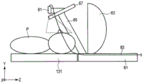
Fig. 16 is a diagram showing the portable screen device 15 of the 1 st projection form P1 from the side of the gantry 11. Fig. 17 is a view showing the portable screen device 15 of the 1 st presentation format P1 from the front of the stand 11. As shown in fig. 16 and 17, in the 1 st presentation form P1, the movable screen device 15 is configured, for example, such that the end surface 610 of the movable carriage 61 is located at the bed-side end PE1 of the bore 53. Thus, the screen 63 is disposed at or near the bed-side end PE1 of the cavity hole 53 (hereinafter referred to as the bed-side end). In the 1 st projection form P1, the bed-side end portion where the screen 63 is disposed may be disposed from the bed-side end PE1 of the cavity 53 toward the inside of the cavity 53 or may be disposed outside the cavity 53, as long as the inside of the cavity 53 is not recognized when the screen 63 is viewed from the outside of the cavity 53. By being disposed at the bed-side end portion, the screen 63 blocks the bore 53, and thus the patient P can be prevented from seeing the inside of the bore 53. At this time, since the image PI is displayed on the screen 63, the patient P is made to be aware of the examination space through the cavity 53, and the fear of entering the cavity 53 can be reduced.
In the 1 st presentation format P1, the reflecting plate 67 may be held at an angle that does not obstruct the view of the patient P or the like in order to improve the visibility of the screen 63 from outside the gantry 11. For example, as described above, the angle of the reflection plate 67 around the rotation axis RR1 may be maintained substantially horizontal by the support arm 65. The angle of the reflection plate 67 in the 1 st projection form P1 is not limited to a substantially horizontal level, and may be determined to be any angle according to the physique of the patient P.
When step S2 is performed and the image projected onto the portable screen device 15 is viewed, the patient P is placed on the top board (step S3). In step S3, the head of the patient P is fixed by the patient fixing tool 137 of the top plate 131.
When step S3 is performed, the top panel 131 is raised, and the top panel 131 and the portable screen device 15 are connected (step S4). Specifically, in step S4, the healthcare professional presses an up button provided on the gantry 11 or the bed 13. Upon receiving the pressing of the up button, the imaging control circuit 31 supplies an electric signal (hereinafter referred to as an up signal) corresponding to the up of the top plate 131 to the bed driving device 135. The couch driving unit 135, which receives the elevation signal, elevates the top plate 131 in the Y-axis direction. When the top plate 131 is raised, the groove 139 of the top plate 131 is fitted to the hook 69 of the mobile screen device 15 as described above, and the top plate 131 is coupled to the mobile screen device 15. A mode in which an image is projected onto the portable screen device 15 in a state in which the portable screen device 15 is connected to the top plate 131 is referred to as a 2 nd projection mode P2.
When step S4 is performed, the projection based on the 1 st presentation form P1 ends. The projection of the video image according to the 1 st presentation format P1 does not necessarily have to be completed after the connection between the top panel 131 and the portable screen device 15 is made (S4). For example, the projection of the video image according to the 1 st presentation format P1 may be terminated during a period from when the patient P is placed on the top board until the top board 131 and the portable screen device 15 are connected. The projector 100 receives the supply of the projection stop signal from the projector control device 200, and terminates the projection of the video. The projector control device 200 receives an image stop instruction from a healthcare professional via an input circuit or the like, for example, and supplies the projection stop signal to the projector 100.
In step S4, the projector control device 200 controls the projector 100 to project a predetermined video image onto the portable screen device 15 (2 nd projection format P2). Specifically, the healthcare practitioner inputs a screening instruction via the input circuit of the screen control device 200. Upon receiving the projection instruction, the projector control device 200 transmits image data of a predetermined video to the projector 100. Upon receiving the image data, the projector 100 projects an image corresponding to the received image data to the mobile screen device 15. The images may be the same as or different from the images projected in the 1 st presentation form P1.
When the projection of the picture based on the 2 nd presentation format P2 is started, the top panel 131 is inserted into the cavity hole 53 (step S5). In step S5, the healthcare practitioner presses an insertion button provided on the gantry 11 or the bed 13. Upon receiving the press of the insertion button, the imaging control circuit 31 supplies an electric signal (hereinafter, referred to as an insertion signal) corresponding to the insertion of the top plate 131 to the couch driving device 135. The couch driving unit 135, which receives the insertion signal, slides the top plate 131 in the + Z-axis direction. Since the top plate 131 is coupled to the portable screen device 15, the portable screen device 15 also slides in the + Z-axis direction in conjunction with the sliding of the top plate 131. When the top plate 131 slides to the imaging position, the healthcare practitioner ends the pressing of the insertion button to stop the top plate.
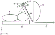
Fig. 18 is a diagram showing the portable screen device 15 of the 2 nd projection format P2 from the side of the gantry 11. As shown in fig. 18, in the 2 nd projection format P2, the patient P placed on the top board 131 can view the image projected on the surface of the screen 63 through the reflection plate 67. Since the top plate 131 is coupled to the mobile screen device 15, the distance between the patient P and the screen 63 is kept constant regardless of the Z-axis direction sliding of the mobile screen device 15. This improves the feeling of input to the image displayed on the screen 63, and alleviates the feeling of occlusion in the cavity hole 53. The projection of the video image in the 2 nd presentation format P2 continues from the end of step S4 to the end of S7.
When step S5 is performed, MR imaging is performed (step S6). In step S6, the healthcare practitioner presses a start button of MR imaging. When the start button is pressed, the imaging control circuit 31 synchronously controls the gradient magnetic field power supply 21, the transmission circuit 23, and the reception circuit 25 in accordance with a preset imaging sequence, and executes MR imaging. MR signals relating to the patient P are collected by the receiving circuit 25 by MR imaging, and an MR image is reconstructed based on the MR signals by the reconstruction circuit 32. While the MR imaging is performed, the patient P can view the image reflected on the screen 63 through the reflecting plate 67. Therefore, even in the case of MR imaging for a relatively long time, the patient can comfortably pass through the bore 53.
When the MR imaging is completed in step S6, the top plate 131 is retracted out of the cavity hole 53 (step S7). In step S7, the healthcare professional presses a retraction button provided on the gantry 11 or the bed 13. Upon receiving the depression of the retraction button, the imaging control circuit 31 supplies an electric signal (hereinafter referred to as a retraction signal) corresponding to the retraction of the top plate 131 to the couch driving device 135. The couch driving device 135 which has received the retraction signal slides the top plate 131 in the-Z axis direction. When the top plate 131 slides out of the gantry 11, the mobile screen device 15 is disposed at the bed-side end PE1 of the cavity 53. While the top plate 131 is moved out of the cavity 53, the patient P can continue to view the image projected on the screen 63 through the reflecting plate 67.
When step S7 is performed, the projection of the video image according to the 2 nd presentation format P2 is ended. For example, a healthcare practitioner or the like inputs a projection stop instruction via an input circuit of the projector control device 200. Upon receiving the projection stop instruction, the projector control device 200 supplies a stop signal to the projector 100. The projector 100 that has received the stop signal ends the projection of the image.
When step S7 is performed, the top panel 131 is lowered, and the connection between the top panel 131 and the mobile screen device 15 is released (step S8). Specifically, in step S8, the healthcare professional presses a down button provided on the gantry 11 or the bed 13. Upon receiving the depression of the lowering button, the imaging control circuit 31 supplies an electric signal (hereinafter, referred to as a lowering signal) corresponding to the lowering of the top plate 131 to the bed driving device 135. The couch driving unit 135, which receives the lowering signal, lowers the top plate 131 in the Y-axis direction. When the top plate 131 is lowered, the hook 69 of the mobile screen device 15 is disengaged from the groove 139 of the top plate 131 as described above, and the connection between the top plate 131 and the mobile screen device 15 is released. When the top plate 131 is lowered to the initial position, the healthcare practitioner ends the depression of the lowering button.
Thereafter, the patient P gets down from the top plate 131 and exits the examination room.
The above concludes the description of the operation example of the magnetic resonance imaging system 1 according to the present embodiment.
The flow of the MR examination is an example, and the operation example of the magnetic resonance imaging system 1 according to the present embodiment is not limited to the flow. For example, in the above-described flow, the raising button and the inserting button are pressed to move the top plate 131 from the initial position to the imaging position in the cavity 53. However, the present embodiment is not limited to this. For example, an automatic insertion button that instructs the raising and insertion of the top plate 131 together may be pressed. In the above-described flow, the retreat button and the lowering button are pressed to move the top plate 131 from the cavity hole 53 to the initial position. However, the present embodiment is not limited to this. For example, an automatic retraction button that instructs retraction and lowering of the top plate 131 together may be pressed.
As described above, the medical image diagnostic apparatus 10 according to the present embodiment includes the gantry 11, the bed 13, and the mobile screen device 15. The gantry 11 has a cavity 53 and is equipped with a medical imaging mechanism. The couch 13 moves the top plate 131 along the central axis Z of the bore 53. In addition, a movable screen device 15 is provided in the cavity 53. The mobile screen device 15 includes a mobile carriage 61, a screen 63, a reflecting plate 67, and a support arm 65. The movable carriage 61 is provided separately from the top plate 131 and is provided movably along the center axis Z of the cavity 53. The screen 63 is provided on the movable carriage 61, and projects an image from the projector 100. The reflection plate 67 reflects the image projected onto the screen 63. The support arm 65 is provided on the traveling carriage 61 and supports the reflection plate 67.
With the above configuration, the medical image diagnostic apparatus 10 according to the present embodiment can realize: a 1 st projection mode of projecting an image onto the portable screen device 15 in a state where the portable screen device 15 is disposed at the bed-side end PE1 of the cavity 53; and a 2 nd projection mode for projecting an image onto the mobile screen device 15 in a state where the top plate 131 is connected to the mobile screen device 15. Before the patient P is placed on the top board 131, the projection of the image of the 1 st projection mode is performed. In the 1 st projection mode, the image can be projected toward the screen 63 while the bore 53 is blocked by the screen 63. Accordingly, the patient P outside the cavity hole 53 can view the image displayed on the screen 63 without visually checking the inside of the cavity hole 53. The projection of the image of the 2 nd projection format is performed in a state where the patient P is placed on the top panel 131 and the top panel 131 is connected to the mobile screen device 15. Typically, the MR imaging is performed when the patient P placed on the top plate 131 is inserted into the bore 53.
As described above, the portable screen device 15 includes the screen 63 and the reflecting plate 67, the screen 63 is disposed behind the head of the patient P, and the reflecting plate that reflects the image projected on the screen 63 is disposed in front of the patient P. In the 2 nd projection mode, since the top panel 131 is connected to the portable screen device 15, the distance between the screen 63 and the reflecting plate 67 can be kept constant regardless of the movement of the top panel 131. Therefore, an image of a predetermined size can be always displayed on the reflection plate 67. Further, according to the present embodiment, since it is not necessary to attach a structure covering the head of the patient P such as a head coil or a head-mounted display, the patient P can view a video image with a large visual field without feeling a sense of occlusion. Further, compared to the case where the reflection plate 67 is attached to the head coil, it is not necessary to provide the mobile screen device 15 according to the photographing region and the coil shape.
As described above, by continuously performing the 1 st projection mode and the 2 nd projection mode, the patient P can end the MR imaging without visually confirming the inside of the bore 53 once after entering the examination room. Thus, the patient P does not recognize the bore 53, and can enjoy an image without feeling a sense of occlusion in MR imaging, as compared with a case where an image is viewed in the bore 53 after the bore 53 is visually recognized. In the 1 st projection mode, since the screen 63 is disposed at the end portion on the bed side, which is the entrance of the bore 53, and the image is projected onto the screen 63, the patient P can be made to recognize the bore 53 as an image projection space. This also reduces the feeling of uneasiness of the patient P when the top plate 131 is inserted into the cavity hole 53.
As described above, according to the present embodiment, the housing property in the cavity of the gantry 11 can be improved.
(application example 1)
In the above embodiment, the support arm 65 is slidably supported by the slide mechanism. However, the present embodiment is not limited to this. For example, the support arm 65 may be provided to be rotatable by a link mechanism.
Fig. 19 is a diagram schematically showing the portable screen device 15 of application example 1. As shown in fig. 19, the traveling carriage 61 is provided with a link mechanism 73. The link mechanism 73 supports the support arm 65 so as to be rotatable along the rotation axis RR 3. The pivot RR3 allows the support arm 65 to be laid down or raised with respect to the movable carriage 61, and thus can be provided parallel to the X axis. Thus, in the 1 st projection mode, the support arm 65 can be laid down toward the traveling carriage 61. By placing the support arm 65 upside down, the reflecting plate 67 and the support arm 65 can be prevented from blocking the visual field of the patient P. In the 2 nd projection mode, the support arm 65 can be raised from the traveling carriage 61. By raising the support arm 65, the patient P or the like placed on the top plate 131 can view the image projected onto the screen 63 through the reflection plate 67.
(application example 2)
In the above embodiment, the support arm 65 is supported by a slide mechanism or a link mechanism. However, the present embodiment is not limited to this. For example, the support arm 65 may be supported by both the slide mechanism and the link mechanism.
Fig. 20 is a diagram schematically showing the portable screen device 15 of application example 2. As shown in fig. 20, the support arm 65 is supported by both the 1 st link mechanism 73 and the slide mechanism 71. For example, the support arm 65 may be supported by the 1 st link mechanism 73 so as to be rotatable about the rotation axis RR3, and the 1 st link mechanism 73 may be supported by the movable carriage 61 via the slide mechanism 71 so as to be slidable on the Z axis. The support arm 65 is configured to be foldable by the 2 nd link mechanism 75. In this case, the support arm 65 includes a 1 st arm 653 provided with the reflection plate 67 so as to be rotatable about the rotation axis RR1, and a 2 nd arm 655 connected to the traveling carriage 61 via a 1 st link mechanism 73, and the 1 st arm 653 and the 2 nd arm 655 are connected to each other so as to be rotatable about a 2 nd rotation axis RR4 by a 2 nd link mechanism 75. In this manner, the support arm 65 can be folded by the 2 nd link mechanism 75. Since the support arm 65 is provided with the 2 nd link mechanism 75, the support arm 65 can be compactly housed, and the degree of freedom of positioning of the reflection plate 67 can be improved.
Further, in order to more compactly store the support arm 65 and further increase the degree of freedom in positioning the reflection plate 67, it is also possible to further increase the degree of freedom in movement of the support arm 65 by further combining a slide mechanism or a link mechanism.
(application example 3)
Fig. 21 is a side view of the mobile screen device 15 of application example 3. Fig. 22 is a side view of the mobile screen device 15 and the stand 11 of application example 3 as a whole. As shown in fig. 21 and 22, the mobile screen device 15 of application example 3 is provided with an optical camera 80 for photographing a patient P placed on a top board 131.
As shown in fig. 22, the optical camera 80 has an objective lens 81 and an optical fiber 83. The optical camera 80 is connected to a CCD (Charge-coupled device). The objective lens 81 and the optical fiber 83 are formed of a nonmagnetic material. The objective lens 81 is provided on the reflecting plate 67 so as to face the face of the patient P placed on the top plate 131. More specifically, the optical camera 80 may be provided on a side surface portion or the like of the reflecting plate 67 so as not to enter the visual field of the patient P viewing the reflecting plate 67. The objective lens 81 converges or diverges light from the patient P. The optical fiber 83 is an optical waveguide for guiding the light from the objective lens 81. The optical fiber 83 connects the objective lens 81 and the CCD85 to guide the light from the objective lens 81 to the CCD85 provided outside the gantry 11. The optical fiber 83 may be attached to the surface of the guide rail 55 or the inner wall 57 of the gantry housing 51, or may be embedded in the guide rail 55 or the gantry housing 51. The CCD85 has a plurality of light receiving elements that receive light from the optical fiber 83 and convert the light into an electrical signal. The CCD85 generates optical image data depicting the face of the patient P based on the electric signals from the plurality of light receiving elements.
Further, since the optical fiber 83 connecting the objective lens 81 and the CCD85 has rigidity, the optical fiber 83 may be damaged as the mobile screen device 15 slides. To prevent this, for example, a mechanism may be provided in which the optical fiber 83 can connect the objective lens 81 and the CCD85 while maintaining a constant curvature, regardless of the sliding of the mobile screen device 15.
The optical image data is supplied to the console 27 via the communication circuit 34. An optical image corresponding to the supplied optical image data is displayed by the display circuit 35. A medical practitioner or the like can monitor the patient P in the MR imaging by observing the optical image.
As described above, in the present embodiment, the optical camera 80 is provided on the mobile screen device 15 disposed in the cavity 53, and therefore can be provided closer to the patient P than a conventional monitoring camera provided outside the gantry 11. This enables, for example, the expression of the patient P in the gantry 11 to be imaged, and thus enables accurate capture of the patient P during MR imaging.
Further, the optical camera 80, more specifically, the objective lens 81 is provided on the reflection plate 67, but the present embodiment is not limited thereto, and may be provided on the support arm 65 as shown in fig. 23 as long as the face of the patient P can be photographed. The optical camera 80, more specifically, the objective lens 81 may be provided on the screen 63 as shown in fig. 24. In the case where the objective lens 81 is provided on the screen 63, it is difficult to make the objective lens 81 face the head of the patient P in accordance with the positional relationship between the screen 63 and the head of the patient P. Therefore, the objective lens 81 may be provided at an end portion of the screen 63 so as to be able to project the head of the patient P via the reflection plate 67.
(application example 4)
In the above application example 3, the optical camera 80 is used for monitoring the patient P. However, the present embodiment is not limited to this. In application example 4, the optical camera 80 is used for collecting physical activity information of the patient P. In application example 4, the optical camera 80 may be provided on the reflection plate 67, the screen 63, or the support arm 65 so as to be able to photograph a portion of the collection target of the body movement. The physical activity information is position information of an arbitrary point or the like that changes with the physical activity of the patient P. The optical image captured by the optical camera 80 includes the positional information of the feature points that changes with the physical movement of the patient P.
In application example 4, the image processing circuit 33 performs body movement correction of the reconstructed image using the optical image captured by the optical camera 80. For example, the image processing circuit 33 tracks the positions of the feature points of the time-series optical images in time series, and calculates the amount of movement of the feature points. The feature points can be set to any portion of the chin, forehead, cervical vertebra, a mark given to the patient P, and the like of the patient P depicted in the optical image. Then, the image processing circuit 33 generates an image in which the body movement is corrected by performing coordinate conversion on the reconstructed image in accordance with the calculated movement amount.
In application example 4, the physical activity information is collected by the optical camera 80. However, the present embodiment is not limited to this. For example, the physical activity information of an arbitrary point of the patient P may be collected by an optical sensor, an ultrasonic sensor, or an acceleration sensor. The optical camera of application example 4 may be provided separately from the monitoring camera of application example 3 for the patient P.
(application example 5)
The portable screen devices 15 of application examples 5 and 6 have a diaphragm that transmits, receives, or transmits/receives sound. The diaphragm is built in, for example, a microphone that receives sound or a speaker that transmits sound. Hereinafter, an example in which the microphone is incorporated in the diaphragm will be described in application example 5, and an example in which the speaker is incorporated in the diaphragm will be described in application example 6.
Fig. 25 is a side view of the mobile screen device 15 of application example 5. Fig. 26 is a side view of the mobile screen device 15 and the stand 11 of application example 5 as a whole.
As shown in fig. 25 and 26, the portable screen device 15 of application example 5 is provided with a microphone 91. The microphone 91 is provided, for example, to collect sound emitted from the patient P. For example, the microphone 91 is attached to the reflection plate 67. The microphone 91 is connected via a cable 93 to an amplifier 95 arranged outside the bore 53. The microphone 91 has, for example, a diaphragm and a transducer by which vibration of the diaphragm caused by sound is converted into an electric signal (sound signal). The sound signal is supplied to the transducer via the cable and amplified by the transducer. The sound signal amplified by the converter is transmitted to the console 27 via wire or wirelessly. The transmitted sound signal is emitted as sound via a speaker or the like provided in the console 27. This enables the voice of the patient P to be transmitted to a healthcare professional in a control room or the like.
The microphone 91 of the present embodiment may be of any type as long as it is nonmagnetic. However, as the microphone 91 of the present embodiment, for example, a highly sensitive and nonmagnetic optical microphone is preferable.
Although the microphone 91 is provided on the reflection plate 67 in the above example, it may be provided at any place as long as it can collect the sound of the patient P. For example, the microphone 91 may be provided in the support arm 65, the screen 63, or another structure of the mobile screen device 15.
The microphone 91 of the present embodiment is not limited to the use for collecting the sound of the patient P. For example, the microphone 91 of the present embodiment may collect the driving sound of the stage 11 in order to use the driving sound for noise cancellation.
(application example 6)
Fig. 27 is a side view of the mobile screen device 15 of application example 6. As shown in fig. 27, the portable screen device 15 of application example 6 is provided with a speaker 97. Specifically, the speaker 97 may be provided to the support arm 65 disposed at a position close to the head of the patient P. The speaker 97 generates sounds corresponding to various uses.
The speaker 97 is connected to the projector control device 200 via a wire or wirelessly. In this case, the speaker 97 may emit, for example, a sound transmitted from the projector control device 200 corresponding to an image projected from the projector 100 to the portable screen device 15. Since the user can watch the image while listening to the sound, the user can more comfortably pass through the cavity 53.
The speaker 97 may be connected to the console 27 by wire or wirelessly. In this case, the speaker 97 may emit the voice of the healthcare practitioner collected by the microphone provided in the console 27. This enables instructions and the like of the healthcare practitioner to be transmitted to the patient P even in MR imaging.
In addition, the speaker 97 of application example 6 may be combined with the microphone 91 of application example 5 in order to communicate with the patient P. By providing the speaker 97 of application example 6 and the microphone 91 of application example 5 in the portable screen device 15, it is possible to have, for example, a conversation between the patient P and the healthcare practitioner. In addition, in the case where the patient P is a child, it is also possible to have the patient P in the bore 53 converse with a parent in the control room. This can reduce the feeling of uneasiness of the patient P as a child in the cavity hole 53, for example.
In addition, the speaker 97 of application example 6 may be combined with the microphone 91 of application example 5 for noise cancellation. In this case, the driving sound of the gantry 11 is collected by the microphone 91, and an electric signal corresponding to the driving sound is transmitted to the console 27. The system control circuit 38 analyzes the sound signal of the driving sound and calculates the phase reversal of the driving sound. Then, the system control circuit 38 generates an acoustic signal (hereinafter referred to as a cancel signal) having an opposite phase to the drive sound. The communication circuit 34 transmits the cancellation signal to the speaker 97. The speaker 97 converts the transmitted cancellation signal into a sound wave (hereinafter, referred to as cancellation sound) and outputs the sound wave. Since the phase of the drive sound of the gantry 11 and the phase of the cancellation sound are in an anti-phase relationship, the drive sound is cancelled by the cancellation sound in the space around the head of the patient P. In the present embodiment, since the microphone 91 and the speaker 97 are provided in the mobile screen device 15 provided in the gantry 11, the driving sound propagated around the patient P can be canceled with higher accuracy. This can reduce the uncomfortable feeling of the patient P due to the driving sound.
(application example 7)
In the 1 st projection mode, the support arm 65 is positioned in front of the screen 63 (the bed 13 side). Therefore, when the patient P outside the gantry 11 views the screen 63, the field of vision may be blocked by the support arm 65. In the 2 nd projection mode, a part of the projection light (hereinafter, referred to as "residual light") emitted from the projector 100 is not irradiated to the screen 63, but is irradiated to a part of the inner wall 57 located in front of the screen 63 through a gap between the residual light and the inner wall 57 of the gantry frame 51. An image corresponding to the excessive light (hereinafter, referred to as an excessive image) is projected on a portion of the inner wall 57. However, depending on the positional relationship between the portion of the inner wall 57 and the head of the patient P, the remaining image may be blocked by the support arm 65 and may not enter the visual field of the patient P. To eliminate these problems, a part or the whole of the support arm 65 may be formed to be transparent. This prevents the support arm 65 from interfering with the visual confirmation of the image projected on the screen 63 in the 1 st mode, and prevents the support arm 65 from interfering with the visual confirmation of the remaining image projected on the portion of the inner wall 57 in the 2 nd mode.
(application example 8)
Fig. 28 is a view showing an XZ cross section (horizontal cross section) of the support arm 65 according to the present embodiment. In fig. 28, the top plate 131 and the traveling carriage 61 are illustrated, but this is because the support arm 65 is not actually at the same height as the top plate 131 and the traveling carriage 61 in order to clarify the positional relationship of the support arm 65. As shown in fig. 28, in the case where the horizontal cross section of the support arm 65 has a rectangular shape, a surface 65A facing the patient P and orthogonal to the X axis enters the visual field of the patient P. In this case, the projection light is irradiated to the surface 65B of the support arm 65 that faces the projector 100 and is orthogonal to the Z axis, and the projection light is not irradiated to the surface 65A of the support arm 65. Therefore, the face 65A is visually recognized as dark for the patient P.
Fig. 29 is a view showing an XZ cross section (horizontal cross section) of the support arm 65' of application example 8. Fig. 29 illustrates the top plate 131 and the mobile carriage 61, but this is for clarifying the positional relationship of the support arm 65 ', and the support arm 65' is not actually at the same height as the top plate 131 and the mobile carriage 61. As shown in fig. 29, the support arm 65 'of application example 8 has a shape capable of reflecting the projection light from the projector 100 toward the inner space RI1 surrounded by the support arm 65'. Specifically, the support arm 65 ' may be formed such that a surface 65 ' a of the support arm 65 ' facing the projector 100 is inclined with respect to the X axis toward the inner space RI 1. For example, as shown in fig. 29, the support arm 65' may be formed to have a triangular shape in a horizontal section. In this case, the surface 65 ' a enters the visual field of the patient P, but since the surface 65 ' a is inclined with respect to the X axis, the surface 65 ' a can reflect the projection light from the projector 100 toward the patient P. Therefore, the patient P can visually confirm the remaining image reflected on the surface 65' a.
(application example 9)
In the above embodiment, the projection light emitted from the projector 100 is directly irradiated to the screen 63. However, the present embodiment is not limited to this. For example, the following modes can be considered. The projector control device 200 is connected to one end (hereinafter referred to as an entrance end) of the optical fiber, and the other end (hereinafter referred to as an exit end) is connected to the non-magnetic projector 100. The nonmagnetic projector 100 is attached to a portion of the traveling carriage 61, the support arm 65, or the reflection plate 67 included in the traveling screen device 15 on the front side (the bed 13 side) of the screen 63 so that the emission port faces the screen 63. According to the above configuration, projection light corresponding to image data transmitted from the projector control device 200 to the projector 100 via the optical fiber can be irradiated onto the surface of the screen 63 (the surface on the bed 13 side). This makes it possible to always display an image of a constant size on the screen 63.
(application example 10)
In the above embodiment, in the case of the 1 st projection mode, the image from the projector 100 is projected onto the screen 63 of the mobile screen device 15 provided at the bed-side end PE1 of the bore 53. However, the present embodiment is not limited to this. For example, another screen may be disposed on the wall surface of the gantry housing 51 on the bed 13 side so as to close the cavity hole 53, and an image may be projected from the projector 100 onto the screen. In this case, the moving screen device 15 may be retracted out of the cavity 53 so as not to block the projected light from the projector 100. Alternatively, the moving screen device 15 may be projected onto the screen from another projector 100 without being retracted to the outside of the cavity 53. The projection target of the 1 st presentation format video is not limited to the screen. For example, the image may be projected by the spatial imaging device in the space of the bed-side end PE1 of the bore 53 so as to block the bore 53.
According to the medical image diagnostic apparatus and the magnetic resonance imaging apparatus according to at least one of the embodiments described above, the habitability of the inside of the bore of the gantry can be improved.
The present invention has been described with reference to several embodiments, which are presented as examples and are not intended to limit the scope of the invention. These new embodiments can be implemented in other various ways, and various omissions, substitutions, and changes can be made without departing from the spirit of the invention. These embodiments and modifications thereof are included in the scope and gist of the invention, and are included in the invention described in the claims and the scope equivalent thereto.
Claims (12)
1. A medical image diagnostic apparatus is provided with:
a stand having a cavity hole and equipped with a medical camera mechanism;
a bed for moving a top plate on which a subject is placed;
a moving body provided separately from the top plate and movable along a center axis of the cavity in association with the top plate;
a screen provided on the movable body;
a reflecting plate for reflecting the image of the screen toward the subject;
a support body provided on the movable body and supporting the reflection plate; and
a connecting portion for connecting the moving body and the top plate,
when the movable body is positioned in the cavity, the connection portion is connected and disconnected.
2. The medical image diagnostic apparatus according to claim 1,
when the movable body is positioned at the bed-side end of the gantry, the connection and disconnection of the connection portions are performed.
3. The medical image diagnostic apparatus according to claim 1,
when the bed-side end of the movable body is positioned at the bed-side end of the gantry, the connection and disconnection of the connection portion are performed.
4. The medical image diagnostic apparatus according to claim 3,
when the bed-side end of the movable body is positioned at the bed-side end of the stand, the screen closes the cavity hole.
5. The medical image diagnostic apparatus according to claim 1,
when the top plate is lowered from a height at which the top plate is coupled to the movable body, the movable body is located at a height at which the top plate is coupled to the movable body.
6. The medical image diagnostic apparatus according to claim 1,
the movable body moves along a guide rail provided on an inner wall of the cavity hole, and when the top plate is lowered from a height at which the top plate is coupled to the movable body, the movable body is positioned on the guide rail.
7. The medical image diagnostic apparatus according to claim 1,
the coupling and decoupling of the coupling portions are performed by the movement of the movable body.
8. The medical image diagnostic apparatus according to claim 1,
when the top plate slides toward the movable body, the movable body is coupled to the top plate via the coupling portion.
9. The medical image diagnostic apparatus according to claim 8,
the connecting part comprises a 1 st connecting part arranged on the moving body and a 2 nd connecting part arranged on the top plate,
the first connecting portion and the second connecting portion are connected by sliding the top plate toward the movable body.
10. The medical image diagnostic apparatus according to claim 9,
the 1 st connecting part is a concave part,
the 2 nd coupling part is a convex part.
11. The medical image diagnostic apparatus according to claim 10,
the 2 nd connecting part is a hook claw,
the hook operates by sliding the top plate toward the movable body, and the hook is fitted in the recess.
12. A magnetic resonance imaging apparatus includes:
a stand having a cavity hole and equipped with a medical camera mechanism;
a bed for moving a top plate on which a subject is placed;
a moving body provided separately from the top plate and movable along a center axis of the cavity in association with the top plate;
a screen provided on the movable body;
a reflecting plate for reflecting the image of the screen toward the subject;
a support body provided on the movable body and supporting the reflection plate; and
a connecting portion for connecting the moving body and the top plate,
when the movable body is positioned in the cavity, the connection portion is connected and disconnected.
Applications Claiming Priority (3)
| Application Number | Priority Date | Filing Date | Title |
|---|---|---|---|
| JP2015-214741 | 2015-10-30 | ||
| JP2015214741A JP6675170B2 (en) | 2015-10-30 | 2015-10-30 | Medical image diagnostic equipment |
| CN201610969212.XA CN106901737B (en) | 2015-10-30 | 2016-10-28 | Medical image diagnosis apparatus and magnetic resonance imaging apparatus |
Related Parent Applications (1)
| Application Number | Title | Priority Date | Filing Date |
|---|---|---|---|
| CN201610969212.XA Division CN106901737B (en) | 2015-10-30 | 2016-10-28 | Medical image diagnosis apparatus and magnetic resonance imaging apparatus |
Publications (1)
| Publication Number | Publication Date |
|---|---|
| CN112545486A true CN112545486A (en) | 2021-03-26 |
Family
ID=58637887
Family Applications (2)
| Application Number | Title | Priority Date | Filing Date |
|---|---|---|---|
| CN201610969212.XA Active CN106901737B (en) | 2015-10-30 | 2016-10-28 | Medical image diagnosis apparatus and magnetic resonance imaging apparatus |
| CN202011398851.8A Pending CN112545486A (en) | 2015-10-30 | 2016-10-28 | Medical image diagnosis apparatus and magnetic resonance imaging apparatus |
Family Applications Before (1)
| Application Number | Title | Priority Date | Filing Date |
|---|---|---|---|
| CN201610969212.XA Active CN106901737B (en) | 2015-10-30 | 2016-10-28 | Medical image diagnosis apparatus and magnetic resonance imaging apparatus |
Country Status (3)
| Country | Link |
|---|---|
| US (1) | US11185293B2 (en) |
| JP (1) | JP6675170B2 (en) |
| CN (2) | CN106901737B (en) |
Families Citing this family (10)
| Publication number | Priority date | Publication date | Assignee | Title |
|---|---|---|---|---|
| JP6822761B2 (en) | 2015-10-30 | 2021-01-27 | キヤノンメディカルシステムズ株式会社 | Medical diagnostic imaging system, magnetic resonance imaging device and video projection program |
| CN107137084A (en) * | 2017-06-20 | 2017-09-08 | 上海联影医疗科技有限公司 | Scanning system |
| JP7076963B2 (en) * | 2017-08-01 | 2022-05-30 | キヤノンメディカルシステムズ株式会社 | Medical diagnostic imaging equipment |
| JP2020535931A (en) * | 2017-10-02 | 2020-12-10 | イノベア メディカル インコーポレーテッド | Systems and methods for displaying images on a patient on a mobile table during medical imaging or treatment |
| DE102018216644A1 (en) * | 2018-09-27 | 2020-04-02 | Siemens Healthcare Gmbh | Magnetic resonance device with a patient communication unit and a method for transmitting at least one communication signal |
| EP3816646A1 (en) * | 2019-10-28 | 2021-05-05 | Koninklijke Philips N.V. | Monitoring system with a camera and non-metallic mirror for magnetic resonance examination system |
| EP4123575A1 (en) * | 2021-07-23 | 2023-01-25 | Koninklijke Philips N.V. | Signal extraction from camera observation |
| WO2023144579A1 (en) * | 2022-01-26 | 2023-08-03 | Mosso Vazquez Jose Luis | Screen for image projection during surgery and a patient assistance projection system. |
| EP4289342A1 (en) * | 2022-06-07 | 2023-12-13 | Koninklijke Philips N.V. | A mirror system for relaying video content to a scanner patient, and a patient support, medical scanner and patient entertainment system using the mirror system |
| WO2023237375A1 (en) | 2022-06-07 | 2023-12-14 | Koninklijke Philips N.V. | A mirror system for relaying video content to a scanner patient, and a patient support, medical scanner and patient entertainment system using the mirror system |
Citations (7)
| Publication number | Priority date | Publication date | Assignee | Title |
|---|---|---|---|---|
| JP2002360543A (en) * | 2001-06-12 | 2002-12-17 | Sangaku Renkei Kiko Kyushu:Kk | Method for deciding synchronizing point in breathing phase and breathing phase monitoring device to be used for it |
| JP2005130975A (en) * | 2003-10-29 | 2005-05-26 | Toshiba Corp | Medical diagnostic apparatus |
| US20060079763A1 (en) * | 2004-09-30 | 2006-04-13 | Varian Medical Systems Technologies, Inc. | Backprojected patient multimedia display |
| CN101103916A (en) * | 2006-07-12 | 2008-01-16 | 株式会社东芝 | Magnetic resonance imaging apparatus |
| CN102988044A (en) * | 2011-09-08 | 2013-03-27 | 三星电子株式会社 | Magnetic resonance imaging device and control thereof |
| JP2013150702A (en) * | 2012-01-25 | 2013-08-08 | Ge Medical Systems Global Technology Co Llc | Monitor device and magnetic resonance apparatus |
| CN103781415A (en) * | 2011-09-22 | 2014-05-07 | 株式会社日立医疗器械 | Medical diagnostic imaging system |
Family Cites Families (23)
| Publication number | Priority date | Publication date | Assignee | Title |
|---|---|---|---|---|
| JPS63102412U (en) * | 1986-12-23 | 1988-07-04 | ||
| JPH0641537Y2 (en) * | 1987-03-26 | 1994-11-02 | 横河電機株式会社 | Head coil for NMR |
| FR2623996A1 (en) | 1987-12-08 | 1989-06-09 | Thomson Csf | PATIENT MONITORING DEVICE IN MEDICAL EXAMINING APPARATUS |
| JP3141419B2 (en) * | 1991-03-30 | 2001-03-05 | 株式会社島津製作所 | Magnetic resonance imaging device |
| US6414490B1 (en) * | 1992-12-18 | 2002-07-02 | Fonar Corporation | MRI magnet with enhanced patient entry and positioning |
| JPH0928689A (en) * | 1995-07-19 | 1997-02-04 | Ge Yokogawa Medical Syst Ltd | Method for collecting mr data and mri apparatus |
| JP3497953B2 (en) | 1996-08-28 | 2004-02-16 | 株式会社日立メディコ | MRI body probe and MRI apparatus |
| JP2000157505A (en) * | 1998-11-30 | 2000-06-13 | Ge Yokogawa Medical Systems Ltd | Table and mri device |
| JP4316126B2 (en) | 2000-01-20 | 2009-08-19 | ジーイー横河メディカルシステム株式会社 | Visual input supply device, signal acquisition device, and image photographing device |
| JP2003190112A (en) | 2001-12-27 | 2003-07-08 | Ge Medical Systems Global Technology Co Llc | Display device and magnetic resonance imaging device |
| JP2004041411A (en) * | 2002-07-11 | 2004-02-12 | Communication Research Laboratory | Visual stimulus showing method in mri and mri apparatus |
| US20040092809A1 (en) * | 2002-07-26 | 2004-05-13 | Neurion Inc. | Methods for measurement and analysis of brain activity |
| US8214012B2 (en) * | 2004-06-17 | 2012-07-03 | Psychology Software Tools, Inc. | Magnetic resonance imaging having patient video, microphone and motion tracking |
| US20060074305A1 (en) | 2004-09-30 | 2006-04-06 | Varian Medical Systems Technologies, Inc. | Patient multimedia display |
| JP2009014962A (en) * | 2007-07-04 | 2009-01-22 | Victor Co Of Japan Ltd | Image display device |
| CN203935185U (en) * | 2011-11-18 | 2014-11-12 | 株式会社日立医疗器械 | Medical imaging camera head, medical imaging camera head bed and pedal unit |
| JP2013226277A (en) * | 2012-04-26 | 2013-11-07 | Ge Medical Systems Global Technology Co Llc | Medical apparatus |
| KR101525013B1 (en) * | 2012-11-05 | 2015-06-16 | 삼성전자주식회사 | Magnetic resonance imaging apparatus |
| WO2014147519A1 (en) * | 2013-03-20 | 2014-09-25 | Koninklijke Philips N.V. | Neurophysiological monitoring for prospective motion gating in radiological imaging |
| JP2014195616A (en) * | 2013-03-29 | 2014-10-16 | 株式会社日立メディコ | Medical image capturing device |
| JP2014212945A (en) * | 2013-04-25 | 2014-11-17 | ジーイー・メディカル・システムズ・グローバル・テクノロジー・カンパニー・エルエルシー | Magnetic resonance system |
| CN204076246U (en) | 2014-04-04 | 2015-01-07 | 郑州大学 | A kind of dining room service robot food delivery constructional device |
| DE102014226467B4 (en) * | 2014-12-18 | 2023-06-15 | Siemens Healthcare Gmbh | Medical imaging device with a frame member for arranging a component |
-
2015
- 2015-10-30 JP JP2015214741A patent/JP6675170B2/en active Active
-
2016
- 2016-10-27 US US15/336,354 patent/US11185293B2/en active Active
- 2016-10-28 CN CN201610969212.XA patent/CN106901737B/en active Active
- 2016-10-28 CN CN202011398851.8A patent/CN112545486A/en active Pending
Patent Citations (7)
| Publication number | Priority date | Publication date | Assignee | Title |
|---|---|---|---|---|
| JP2002360543A (en) * | 2001-06-12 | 2002-12-17 | Sangaku Renkei Kiko Kyushu:Kk | Method for deciding synchronizing point in breathing phase and breathing phase monitoring device to be used for it |
| JP2005130975A (en) * | 2003-10-29 | 2005-05-26 | Toshiba Corp | Medical diagnostic apparatus |
| US20060079763A1 (en) * | 2004-09-30 | 2006-04-13 | Varian Medical Systems Technologies, Inc. | Backprojected patient multimedia display |
| CN101103916A (en) * | 2006-07-12 | 2008-01-16 | 株式会社东芝 | Magnetic resonance imaging apparatus |
| CN102988044A (en) * | 2011-09-08 | 2013-03-27 | 三星电子株式会社 | Magnetic resonance imaging device and control thereof |
| CN103781415A (en) * | 2011-09-22 | 2014-05-07 | 株式会社日立医疗器械 | Medical diagnostic imaging system |
| JP2013150702A (en) * | 2012-01-25 | 2013-08-08 | Ge Medical Systems Global Technology Co Llc | Monitor device and magnetic resonance apparatus |
Also Published As
| Publication number | Publication date |
|---|---|
| CN106901737A (en) | 2017-06-30 |
| JP2017080298A (en) | 2017-05-18 |
| US20170119320A1 (en) | 2017-05-04 |
| JP6675170B2 (en) | 2020-04-01 |
| CN106901737B (en) | 2020-12-25 |
| US11185293B2 (en) | 2021-11-30 |
Similar Documents
| Publication | Publication Date | Title |
|---|---|---|
| CN106901737B (en) | Medical image diagnosis apparatus and magnetic resonance imaging apparatus | |
| US20230329655A1 (en) | Systems and methods for displaying images to patient residing on movable table during medical imaging or therapeutic procedures | |
| KR101759967B1 (en) | Medical imaging device having a frame element for disposing a component | |
| JP6775943B2 (en) | Medical diagnostic imaging equipment | |
| US8805476B2 (en) | Magnetic resonance imaging device and control method thereof | |
| KR101604811B1 (en) | Magnetic resonance imaging apparatus | |
| US10412377B2 (en) | Augmented display device for use in a medical imaging laboratory | |
| JP2003190112A (en) | Display device and magnetic resonance imaging device | |
| JP2014195616A (en) | Medical image capturing device | |
| JP6822761B2 (en) | Medical diagnostic imaging system, magnetic resonance imaging device and video projection program | |
| WO2008120152A1 (en) | Optical-image transmission device | |
| US20130021034A1 (en) | Magnetic resonance device | |
| JP2017080299A (en) | Magnetic resonance imaging apparatus | |
| JP6956819B2 (en) | Medical diagnostic imaging equipment and medical diagnostic imaging system | |
| JP6702700B2 (en) | Medical image diagnostic system, medical image diagnostic apparatus, and video projection program | |
| JP2018064889A (en) | Magnetic resonance imaging system, magnetic resonance imaging device and image projection program | |
| JP2018029763A (en) | Medical image diagnostic system | |
| JP7098694B2 (en) | Medical diagnostic imaging equipment | |
| CN114615931A (en) | Monitoring system with camera and non-metallic mirror for magnetic resonance examination system | |
| KR101574537B1 (en) | Method and device for controlling function of magnetic resonance imaging device | |
| JP2023143352A (en) | Medical image diagnostic device and video projection device | |
| US20160235335A1 (en) | Magnetic resonance imaging (mri) apparatus and method of controlling mri apparatus | |
| US20220280125A1 (en) | X-ray bed |
Legal Events
| Date | Code | Title | Description |
|---|---|---|---|
| PB01 | Publication | ||
| PB01 | Publication | ||
| SE01 | Entry into force of request for substantive examination | ||
| SE01 | Entry into force of request for substantive examination |