CN112538967A - Shear wall template is to drawing connecting piece and template reinforced structure thereof - Google Patents
Shear wall template is to drawing connecting piece and template reinforced structure thereof Download PDFInfo
- Publication number
- CN112538967A CN112538967A CN202011492556.9A CN202011492556A CN112538967A CN 112538967 A CN112538967 A CN 112538967A CN 202011492556 A CN202011492556 A CN 202011492556A CN 112538967 A CN112538967 A CN 112538967A
- Authority
- CN
- China
- Prior art keywords
- shear wall
- wall template
- pair
- pulling
- reinforcing
- Prior art date
- Legal status (The legal status is an assumption and is not a legal conclusion. Google has not performed a legal analysis and makes no representation as to the accuracy of the status listed.)
- Granted
Links
Images


Classifications
-
- E—FIXED CONSTRUCTIONS
- E04—BUILDING
- E04G—SCAFFOLDING; FORMS; SHUTTERING; BUILDING IMPLEMENTS OR AIDS, OR THEIR USE; HANDLING BUILDING MATERIALS ON THE SITE; REPAIRING, BREAKING-UP OR OTHER WORK ON EXISTING BUILDINGS
- E04G17/00—Connecting or other auxiliary members for forms, falsework structures, or shutterings
- E04G17/06—Tying means; Spacers ; Devices for extracting or inserting wall ties
- E04G17/065—Tying means, the tensional elements of which are threaded to enable their fastening or tensioning
-
- E—FIXED CONSTRUCTIONS
- E04—BUILDING
- E04G—SCAFFOLDING; FORMS; SHUTTERING; BUILDING IMPLEMENTS OR AIDS, OR THEIR USE; HANDLING BUILDING MATERIALS ON THE SITE; REPAIRING, BREAKING-UP OR OTHER WORK ON EXISTING BUILDINGS
- E04G17/00—Connecting or other auxiliary members for forms, falsework structures, or shutterings
- E04G17/001—Corner fastening or connecting means for forming or stiffening elements
-
- E—FIXED CONSTRUCTIONS
- E04—BUILDING
- E04G—SCAFFOLDING; FORMS; SHUTTERING; BUILDING IMPLEMENTS OR AIDS, OR THEIR USE; HANDLING BUILDING MATERIALS ON THE SITE; REPAIRING, BREAKING-UP OR OTHER WORK ON EXISTING BUILDINGS
- E04G17/00—Connecting or other auxiliary members for forms, falsework structures, or shutterings
- E04G17/06—Tying means; Spacers ; Devices for extracting or inserting wall ties
- E04G17/065—Tying means, the tensional elements of which are threaded to enable their fastening or tensioning
- E04G17/0651—One-piece elements
- E04G17/0652—One-piece elements fully recoverable
-
- E—FIXED CONSTRUCTIONS
- E04—BUILDING
- E04G—SCAFFOLDING; FORMS; SHUTTERING; BUILDING IMPLEMENTS OR AIDS, OR THEIR USE; HANDLING BUILDING MATERIALS ON THE SITE; REPAIRING, BREAKING-UP OR OTHER WORK ON EXISTING BUILDINGS
- E04G17/00—Connecting or other auxiliary members for forms, falsework structures, or shutterings
- E04G17/06—Tying means; Spacers ; Devices for extracting or inserting wall ties
- E04G17/065—Tying means, the tensional elements of which are threaded to enable their fastening or tensioning
- E04G17/0655—Tying means, the tensional elements of which are threaded to enable their fastening or tensioning the element consisting of several parts
- E04G17/0657—Tying means, the tensional elements of which are threaded to enable their fastening or tensioning the element consisting of several parts fully recoverable
Landscapes
- Engineering & Computer Science (AREA)
- Architecture (AREA)
- Mechanical Engineering (AREA)
- Civil Engineering (AREA)
- Structural Engineering (AREA)
- Forms Removed On Construction Sites Or Auxiliary Members Thereof (AREA)
Abstract
The invention relates to a shear wall formwork split connecting piece and a formwork reinforcing structure thereof, and belongs to the technical field of wall formwork reinforcement. The shear wall template split connecting pieces are arranged in pairs when in use and comprise diagonal pulling reinforcing components and straight pulling reinforcing components which are detachably connected together, the diagonal pulling reinforcing components are used for being arranged on two adjacent shear wall templates to perform diagonal pulling reinforcement on the two adjacent shear wall templates, and the straight pulling reinforcing components are used for performing split pulling reinforcement on the two shear wall templates which are arranged in parallel at intervals; the shear wall template reinforcing structure comprises a shear wall template and the shear wall template split connecting piece. Shear wall template is to drawing connecting piece and template reinforced structure can follow slant and horizontal direction two directions simultaneously and consolidate the shear wall template, and not only save material can guarantee when concreting simultaneously, the shear wall template can not take place the come-up and rise the mould phenomenon to the quality of the shear wall after the assurance shaping.
Description
Technical Field
The invention belongs to the technical field of wall formwork reinforcement, and particularly relates to a shear wall formwork split connecting piece and a formwork reinforcing structure thereof.
Background
Shear walls, also called wind-resistant walls, earthquake-resistant walls or structural walls, are walls which mainly bear horizontal loads and vertical loads (gravity) caused by wind loads or earthquake action in houses or structures and are used for preventing the structures from being sheared and damaged; shear walls, also known as seismic walls, are generally made of reinforced concrete and have excellent rigidity, strength and collapse resistance. The building formwork is a temporary supporting structure, which is manufactured according to the design requirements, so that the concrete structure and the members are formed according to the specified positions and geometric dimensions, the correct positions of the concrete structure and the members are kept, and the self weight of the building formwork and the external load acting on the building formwork are borne.
In the construction process of a building, a shear wall template for pouring concrete needs to be reinforced, wherein the process of erecting the reinforcing template accounts for more than 95% of the working period of the whole template, the process has high technical requirements, the reinforcing process is complicated, the reinforcing process is particularly difficult for workers in the whole construction industry, and the phenomena of template floating and template expansion can occur once the reinforcing is not firm, so that the construction weight of the shear wall is influenced.
Disclosure of Invention
Aiming at the defects in the prior art, the invention aims to provide a shear wall template counter-pulling connecting piece which can ensure the reinforcing strength of a shear wall template and ensure that the shear wall template is not easy to float upwards and expand; the invention also aims to provide the shear wall template reinforcing structure for ensuring the construction quality of the shear wall.
In order to achieve the purpose, the shear wall template split connecting piece adopts the technical scheme that:
the shear wall template split connecting pieces comprise diagonal pulling reinforcing components and straight pulling reinforcing components, the diagonal pulling reinforcing components and the straight pulling reinforcing components are detachably connected together, the shear wall template split connecting pieces are used in pairs, the diagonal pulling reinforcing components are used for being arranged on two adjacent shear wall templates to perform diagonal pulling reinforcement on the two adjacent shear wall templates, and the straight pulling reinforcing components are used for performing split pulling reinforcement on the two shear wall templates which are arranged in parallel at intervals;
the diagonal reinforcement member includes:
the framework is of an inverted T-shaped structure and comprises a bottom plate and a vertical plate connected with the bottom plate, the bottom plate is used for being arranged in parallel with a corresponding shear wall template, and a counter-pulling hole for a counter-pulling screw to penetrate through is formed in the joint of the bottom plate and the vertical plate;
the support beam is obliquely arranged, one end of the support beam is fixedly connected with the vertical plate, the other end of the support beam is fixedly connected with the bottom plate, and the support beam is provided with a counter-pulling screw rod through hole which corresponds to the counter-pulling hole and is used for a counter-pulling screw rod to pass through;
the compaction assembly is connected to one side of the bottom plate, which faces the shear wall template, and is used for compacting the corresponding shear wall template when the paired two diagonal reinforcement assemblies are fastened and connected;
the straight pull reinforcement assembly includes:
the first pull rod pair is in threaded connection with a first butterfly clamp, a first fastening nut and a first positioning nut, the first fastening nut and the first positioning nut are respectively positioned on two sides of the first butterfly clamp, and the first positioning nut is used for being matched with one stop of two shear wall templates which are arranged in parallel at intervals;
the second pair of pull rods and the first pair of pull rods are staggered in the direction parallel to the vertical plate and are arranged in opposite directions, a second butterfly clamp, a second fastening nut and a second positioning nut are connected to the second pair of pull rods in a threaded mode, the second fastening nut and the second positioning nut are located on two sides of the second butterfly clamp respectively, the second positioning nut is used for being matched with the other stop of the two shear wall templates which are arranged in parallel at intervals, and positioning steel pipes are arranged in the first butterfly clamp and the second butterfly clamp;
the connecting block is in threaded connection with the first pair of pull rods and the second pair of pull rods simultaneously, and the first pair of pull rods and the second pair of pull rods penetrate through the connecting block and are used for adjusting the distance between the first positioning nut and the second positioning nut.
The beneficial effects of the above technical scheme are: the shear wall template split connecting piece is used in pairs when reinforcing the shear wall templates, namely two diagonal-pulling reinforcing components are respectively placed on two adjacent shear wall templates to perform diagonal reinforcement on the two shear wall templates, and at the moment, two straight-pulling reinforcing components respectively perform split reinforcement on four shear wall templates in the horizontal, transverse and longitudinal directions; because draw to one side and consolidate the subassembly and directly draw and consolidate subassembly releasable connection together, so can also save material, still be convenient for installation and dismantlement realize the turnover and use. In addition, because the straight-pull reinforcing assembly is arranged between two opposite pull rods in a staggered manner and is connected with the connecting block through threads, the distance between the positioning nuts on the two opposite pull rods can be adjusted by adjusting the positions of the two opposite pull rods through the adjusting connecting block, and then the reinforcement of two shear wall templates with different intervals can be met, so that the application range of the shear wall template opposite-pull connecting piece is widened. The shear wall template split connecting piece can reinforce the shear wall template from an oblique direction and a vertical direction at the same time, so that the shear wall template is not easy to expand and float when concrete is poured, and the construction quality of the shear wall is ensured.
Furthermore, the supporting beams are arranged in pairs and are provided with at least two pairs, the two supporting beams in pairs are symmetrically distributed on two sides of the vertical plate, and the supporting beams positioned on the same side of the vertical plate are parallel to each other.
Has the advantages that: the structure of the diagonal reinforcement component is symmetrical and stable, the stress is uniform, and the reinforcement effect of the diagonal reinforcement component is enhanced.
Furthermore, the compaction assembly comprises a reinforcing groove with a notch back to the bottom plate and channel steel with notches arranged at intervals with the reinforcing groove and facing the bottom plate, through holes for the first pair of pull rods to pass through are formed in the groove surface of the channel steel for abutting against the corresponding shear wall template, the reinforcing groove is a U-shaped groove, and I-shaped steel is fixedly connected in the U-shaped groove; or the reinforcing groove is an arc-shaped groove, and a jacking steel pipe is assembled in the arc-shaped groove in an interference fit mode.
Has the advantages that: structural strength is high, when fastening to the drawing screw rod, can guarantee to compress tightly the effect that compresses tightly of subassembly to shear force wall template, also is convenient for simultaneously realize the straight-pull reinforcement subassembly and draw the installation and the dismantlement between the reinforcement subassembly to one side.
Furthermore, wheels are mounted on the bottom plate through mounting beams, and the distance between the bottommost ends of the wheels and the bottom plate is adjustable.
Has the advantages that: during installation, the position of the diagonal reinforcement component on the shear wall template can be adjusted conveniently.
Furthermore, the bottom plate is provided with a through hole for the mounting beam to move up and down, and a sliding hole which is communicated with the through hole and is vertical to the axis of the through hole, and a fastening bolt for fastening the mounting beam is assembled in the sliding hole in a sliding manner.
Has the advantages that: the position of the wheel relative to the shear wall template is convenient to adjust, so that the situation that the wheel moves to cause insecure fastening when the wheel is fastened is avoided.
The technical scheme of the shear wall template reinforcing structure is as follows:
the shear wall template reinforcing structure comprises shear wall templates and shear wall template split connecting pieces, wherein the shear wall template split connecting pieces comprise diagonal pulling reinforcing components and straight pulling reinforcing components, the diagonal pulling reinforcing components and the straight pulling reinforcing components are detachably connected together, the shear wall template split connecting pieces are used in pairs, the diagonal pulling reinforcing components are arranged on the two adjacent shear wall templates to perform diagonal pulling reinforcement on the two adjacent shear wall templates, and the straight pulling reinforcing components are used for performing split reinforcing on the two shear wall templates which are arranged in parallel at intervals;
the diagonal reinforcement member includes:
the framework is of an inverted T-shaped structure and comprises a bottom plate and a vertical plate connected with the bottom plate, the bottom plate is used for being arranged in parallel with a corresponding shear wall template, and a counter-pulling hole for a counter-pulling screw to penetrate through is formed in the joint of the bottom plate and the vertical plate;
the support beam is obliquely arranged, one end of the support beam is fixedly connected with the vertical plate, the other end of the support beam is fixedly connected with the bottom plate, and the support beam is provided with a counter-pulling screw rod through hole which corresponds to the counter-pulling hole and is used for a counter-pulling screw rod to pass through;
the reinforcing components are connected to one side of the bottom plate, which faces the shear wall template, and are used for compressing the corresponding shear wall template when the two diagonal reinforcing components in pair are fastened and connected;
the straight pull reinforcement assembly includes:
the first pull rod pair is in threaded connection with a first butterfly clamp, a first fastening nut and a first positioning nut, the first fastening nut and the first positioning nut are respectively positioned on two sides of the first butterfly clamp, and the first positioning nut is used for being matched with one stop of two shear wall templates which are arranged in parallel at intervals;
the second pair of pull rods and the first pair of pull rods are staggered in the direction parallel to the vertical plate and are arranged in opposite directions, a second butterfly clamp, a second fastening nut and a second positioning nut are connected to the second pair of pull rods in a threaded mode, the second fastening nut and the second positioning nut are located on two sides of the second butterfly clamp respectively, the second positioning nut is used for being matched with the other stop of the two shear wall templates which are arranged in parallel at intervals, and positioning steel pipes are arranged in the first butterfly clamp and the second butterfly clamp;
the connecting block is in threaded connection with the first pair of pull rods and the second pair of pull rods simultaneously, and the first pair of pull rods and the second pair of pull rods penetrate through the connecting block and are used for adjusting the distance between the first positioning nut and the second positioning nut.
The beneficial effects of the above technical scheme are: the shear wall template reinforcing structure adopts shear wall template split connecting pieces arranged in pairs to reinforce shear wall templates, namely two diagonal-pulling reinforcing components are respectively placed on two adjacent shear wall templates to perform diagonal reinforcement on the two shear wall templates, and at the moment, two straight-pulling reinforcing components respectively perform split reinforcement on four shear wall templates in the horizontal, transverse and longitudinal directions; because draw to one side and consolidate the subassembly and directly draw and consolidate subassembly releasable connection together, so can also save material, still be convenient for installation and dismantlement realize the turnover and use. In addition, because the straight-pull reinforcing assembly is arranged between two opposite pull rods in a staggered manner and is connected with the connecting block through threads, the distance between the positioning nuts on the two opposite pull rods can be adjusted by adjusting the positions of the two opposite pull rods through the adjusting connecting block, and then the reinforcement of two shear wall templates with different intervals can be met, so that the application range of the shear wall template opposite-pull connecting piece is widened. The shear wall template split connecting piece can reinforce the shear wall template from an oblique direction and a vertical direction at the same time, so that the shear wall template is not easy to expand and float when concrete is poured, and the construction quality of the shear wall is ensured.
Furthermore, the supporting beams are arranged in pairs and are provided with at least two pairs, the two supporting beams in pairs are symmetrically distributed on two sides of the vertical plate, and the supporting beams positioned on the same side of the vertical plate are parallel to each other.
Has the advantages that: the structure of the diagonal reinforcement component is symmetrical and stable, the stress is uniform, and the reinforcement effect of the diagonal reinforcement component is enhanced.
Furthermore, the reinforcing assembly comprises a reinforcing groove with a notch back to the bottom plate and channel steel with notches arranged at intervals with the reinforcing groove and facing the bottom plate, through holes for the first pair of pull rods to pass through are formed in the groove surface of the channel steel for abutting against the corresponding shear wall template, the reinforcing groove is a U-shaped groove, and I-shaped steel is fixedly connected in the U-shaped groove; or the reinforcing groove is an arc-shaped groove, and a jacking steel pipe is assembled in the arc-shaped groove in an interference fit mode.
Has the advantages that: structural strength is high, when fastening to the drawing screw rod, can guarantee to compress tightly the effect that compresses tightly of subassembly to shear force wall template, also is convenient for simultaneously realize the straight-pull reinforcement subassembly and draw the installation and the dismantlement between the reinforcement subassembly to one side.
Furthermore, the bottom plate is provided with wheels through the mounting beams, the distance between the bottom ends of the wheels and the bottom plate is adjustable, the bottom plate is provided with through holes for the mounting beams to move up and down, the bottom plate is also provided with sliding holes which are communicated with the through holes and are vertical to the axes of the through holes, and the sliding holes are internally provided with fastening bolts for fastening the mounting beams in a sliding manner.
Has the advantages that: the position of the wheel relative to the shear wall template is convenient to adjust, so that the situation that the wheel moves to cause insecure fastening when the wheel is fastened is avoided.
Further, the shear wall template still includes square pipe and skid, and square pipe setting is in the outside with the shear wall template parallel arrangement who strengthens the subassembly contact to one side with drawing to one side, and the skid setting is between this shear wall template and square pipe, and first pair of pull rod or second pair of pull rod pass square pipe and the shear wall template that corresponds with square pipe simultaneously, and first butterfly card or second butterfly card are located one side of square pipe back to the skid.
Has the advantages that: further consolidate the shear force wall template, avoid appearing the mould come-up phenomenon that rises.
Drawings
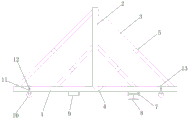
FIG. 1 is a general schematic view of a shear wall form reinforcing structure of the present invention;
FIG. 2 is a schematic structural view of a shear wall form counter-pulling connector of the present invention;
FIG. 3 is a schematic structural view of a diagonal reinforcement member in the shear wall form diagonal connection member of the present invention;
fig. 4 is a schematic structural diagram of a straight pull reinforcing component in the shear wall formwork counter-pull connecting piece.
Description of reference numerals: the method comprises the following steps of 1-a bottom plate, 2-a vertical plate, 3-a supporting beam, 4-a split hole, 5-a split screw perforation, 6-a split screw, 7-a reinforcing groove, 8-I-steel, 9-channel steel, 10-a wheel, 11-a sliding hole, 12-a fastening bolt, 13-an installation beam, 14-a first pair of pull rods, 15-a second pair of pull rods, 16-a first butterfly clamp, 17-a second butterfly clamp, 18-a first fastening nut, 19-a second fastening nut, 20-a first positioning nut, 21-a second positioning nut, 22-a water stop ring, 23-a connecting block, 24-a positioning steel pipe, 25-a square pipe, 26-a skid and 27-a shear wall template.
Detailed Description
The invention is described in further detail below with reference to the drawings and the detailed description.
The shear wall template split connecting piece comprises the following specific embodiments:
as shown in figures 1 and 2, the shear wall template split connecting piece comprises a diagonal pulling reinforcing component and a straight pulling reinforcing component, and the diagonal pulling reinforcing component and the straight pulling reinforcing component are detachably connected together. When in use, the shear wall template split connecting pieces are used in pairs.
Specifically, as shown in fig. 3, the diagonal reinforcement assembly includes a framework in an inverted "T" shape, a support beam 3 connected to the framework, and a compression assembly. The skeleton includes bottom plate 1, with bottom plate 1 welded connection's riser 2 together, riser 2 connects the central point of bottom plate 1 and puts. The bottom plate 1 is used for being arranged in parallel with a corresponding shear wall template 27, and a connecting part of the bottom plate 1 and the vertical plate 2 is provided with a counter-pulling hole 4 for a counter-pulling screw rod 6 to pass through. The supporting beams 3 are arranged in pairs and are provided with two pairs, the two supporting beams 3 in pairs are symmetrically distributed on two sides of the vertical plate 2, and the supporting beams 3 which are positioned on the same side of the vertical plate 2 are parallel to each other. Every props roof beam 3 and arranges for bottom plate 1 slope, props roof beam 3's one end and riser 2 fixed connection, props roof beam 3's the other end and bottom plate 1 fixed connection, props and is equipped with the split screw perforation 5 that supplies to pass split screw 6 that corresponds with split hole 4 on the roof beam 3. When the shear wall template is obliquely reinforced, the opposite-pulling screw 6 simultaneously penetrates through the opposite-pulling hole 4 and the opposite-pulling screw through hole 5, and the two oblique-pulling reinforcing components are fastened and connected together. The compressing components are connected to one side of the bottom plate 1 facing the shear wall formworks 27 and used for compressing the corresponding shear wall formworks 27 when the paired two diagonal reinforcing components are tightly connected. Referring to fig. 3, the pressing assembly comprises a reinforcing groove 7 with a notch facing away from the base plate 1 and a channel steel 9 with a notch arranged at an interval with the reinforcing groove 7 and facing the base plate, the reinforcing groove 7 is a U-shaped groove and is defined by two parallel connecting plates arranged at intervals and the base plate, and an i-shaped steel 8 is fixedly connected in the U-shaped groove.
The bottom plate 1 is also provided with wheels 10 through mounting beams 13, and the distance between the bottommost ends of the wheels 10 relative to the bottom plate 1 is adjustable. Specifically, the bottom plate 1 is provided with a through hole for the mounting beam 13 to move up and down, and a slide hole 11 which is communicated with the through hole and has an axis perpendicular to the axis of the through hole, and a fastening bolt 12 for fastening the mounting beam 13 is slidably assembled in the slide hole 11. The arrangement of the wheels 10 is beneficial to diagonal pulling of the reinforcing component to adjust the position of the corresponding shear wall template, and meanwhile, the wheels 10 move to cause insecurity in fastening by adjusting the positions of the wheels 10.
As shown in fig. 4, the straight pull reinforcement assembly includes a first pair of tie rods 14, a second pair of tie rods 15, and a connecting block 23. The first butterfly clamp 16, the first fastening nut 18 and the first positioning nut 20 are connected to the first pair of pull rods 14 through threads, the first fastening nut 18 and the first positioning nut 20 are respectively located on two sides of the first butterfly clamp 16, and the first positioning nut 20 is used for being matched with one of two shear wall templates which are arranged in parallel at intervals in a blocking mode. The second pair of pull rods 15 and the first pair of pull rods 14 are staggered in the direction parallel to the vertical plate 2 and arranged in opposite directions, a second butterfly clamp 17, a second fastening nut 19 and a second positioning nut 21 are connected to the second pair of pull rods 15 in a threaded manner, the second fastening nut 19 and the second positioning nut 21 are respectively located on two sides of the second butterfly clamp 17, the second positioning nut 21 is used for being in blocking fit with the other one of the two shear wall templates arranged in parallel at intervals, and positioning steel pipes 24 are arranged in the first butterfly clamp 16 and the second butterfly clamp 17. All be equipped with seal ring 22 on first pair of pull rod 14 and the second pair of pull rod 15, both all pass connecting block 23 to all with connecting block 23 threaded connection, through rotating first pair of pull rod 14 or second pair of pull rod 15, can adjust connecting block 23 for the distance between two counter-pull rods, thereby adjust the interval between first set nut 20 and the second set nut 21, satisfy the reinforcement to two shear wall templates of different intervals.
The groove face, used for corresponding shear wall template 27 of channel-section steel 9 to push up tightly, is equipped with the via hole that supplies first pair of pull rod 14 to pass on, and first pair of pull rod 14 passes the channel-section steel to fasten through first fastening nut 18, realize the vertical pulling and consolidate the subassembly and draw the detachable connection between the reinforcement subassembly to one side.
The shear wall template split connecting pieces are used in pairs, as shown in fig. 1, two diagonal-pulling reinforcing components are respectively arranged on two adjacent shear wall templates and are fixedly connected together through split screws 6, and at the moment, channel steel 9 and I-steel 8 on the two diagonal-pulling reinforcing components are both propped against the surfaces of the corresponding shear wall templates 27 to compress the shear wall templates 27, so that the external corner die expansion is avoided when concrete is poured. Because the straight pulling reinforcing component and the inclined pulling reinforcing component are assembled together, one straight pulling reinforcing component penetrates through the two shear wall templates which are horizontally arranged in a transverse parallel mode, the other straight pulling reinforcing component penetrates through the two shear wall templates which are horizontally arranged in a longitudinal parallel mode, and all the shear wall templates are positioned from the inner side and the outer side. Therefore, when the shear wall template is reinforced by the counter-pulling connecting piece of the shear wall template, the shear wall template can be reinforced in the oblique direction and the horizontal direction at the same time, the traditional mode that the shear wall template is reinforced in the oblique direction and the horizontal direction respectively is avoided, materials are saved, the reinforcing effect is ensured, the phenomenon of rising of a rising die is avoided, and the construction quality of the shear wall is ensured.
In other embodiments, the bracing beams may be individually disposed on only one side of the riser, with the tie-down reinforcement assembly attached to the base plate at a location on the other side of the riser.
In other embodiments, no wheels may be provided.
In other embodiments, the reinforcing groove may also be an arc-shaped groove, and at this time, a jacking steel pipe is assembled in the arc-shaped groove in an interference manner to jack the shear wall template.
The concrete embodiment of the shear wall template reinforcing structure comprises the following steps:
the shear wall template reinforcing structure comprises a shear wall template 27, shear wall template split connectors, square tubes 25 and skid blocks 26. The structure of the shear wall template counter-pulling connecting piece is completely the same as that of the shear wall template counter-pulling connecting piece in the embodiment, and the structure is not repeated and is directly used. Referring to fig. 1, the square tube 25 is disposed outside the shear wall formwork parallel to the shear wall formwork in contact with the diagonal reinforcement component, the skid 26 is disposed between the shear wall formwork and the square tube 25, at this time, the second pair of pull rods 15 simultaneously penetrate through the square tube 25 and the shear wall formwork 27 corresponding to the square tube 25, the second butterfly clamp 17 is located on one side of the square tube 25, which is opposite to the skid 26, the second fastening nut 19 is tightened to enable the skid 26 to compress the shear wall formwork, and the shear wall formwork is further reinforced under the reinforcement of the diagonal connection member of the shear wall formwork, so that the construction quality of the shear wall is ensured.
In other embodiments, the square tubes and the skid blocks may not be arranged under the condition that the shear wall formwork counter-pulling connecting pieces can ensure the reinforcing effect of the shear wall formwork.
The above-described embodiments of the present invention do not limit the scope of the present invention. Any modification, equivalent replacement, and improvement made within the spirit and principle of the present invention should be included in the scope of the claims of the present invention.
Claims (10)
1. The shear wall template split connecting piece is characterized by comprising an oblique pulling reinforcing component and a straight pulling reinforcing component, wherein the oblique pulling reinforcing component and the straight pulling reinforcing component are detachably connected together;
the diagonal reinforcement member includes:
the framework is of an inverted T-shaped structure and comprises a bottom plate and a vertical plate connected with the bottom plate, the bottom plate is used for being arranged in parallel with a corresponding shear wall template, and a counter-pulling hole for a counter-pulling screw to penetrate through is formed in the joint of the bottom plate and the vertical plate;
the support beam is obliquely arranged, one end of the support beam is fixedly connected with the vertical plate, the other end of the support beam is fixedly connected with the bottom plate, and the support beam is provided with a counter-pulling screw rod through hole which corresponds to the counter-pulling hole and is used for a counter-pulling screw rod to pass through;
the compaction assembly is connected to one side of the bottom plate, which faces the shear wall template, and is used for compacting the corresponding shear wall template when the paired two diagonal reinforcement assemblies are fastened and connected;
the straight pull reinforcement assembly includes:
the first pull rod pair is in threaded connection with a first butterfly clamp, a first fastening nut and a first positioning nut, the first fastening nut and the first positioning nut are respectively positioned on two sides of the first butterfly clamp, and the first positioning nut is used for being matched with one stop of two shear wall templates which are arranged in parallel at intervals;
the second pair of pull rods and the first pair of pull rods are staggered in the direction parallel to the vertical plate and are arranged in opposite directions, a second butterfly clamp, a second fastening nut and a second positioning nut are connected to the second pair of pull rods in a threaded mode, the second fastening nut and the second positioning nut are located on two sides of the second butterfly clamp respectively, the second positioning nut is used for being matched with the other stop of the two shear wall templates which are arranged in parallel at intervals, and positioning steel pipes are arranged in the first butterfly clamp and the second butterfly clamp;
the connecting block is in threaded connection with the first pair of pull rods and the second pair of pull rods simultaneously, and the first pair of pull rods and the second pair of pull rods penetrate through the connecting block and are used for adjusting the distance between the first positioning nut and the second positioning nut.
2. The shear wall template split connection of claim 1, wherein the bracing beams are arranged in pairs, and at least two pairs are provided, and two bracing beams in a pair are symmetrically distributed on two sides of the vertical plate, and the bracing beams on the same side of the vertical plate are parallel to each other.
3. The shear wall template split connecting piece according to claim 1 or 2, wherein the pressing assembly comprises a reinforcing groove with a notch facing away from the bottom plate and a channel steel with a notch facing the bottom plate and arranged at an interval with the reinforcing groove, a through hole for the first pair of pull rods to pass through is formed in a groove surface of the channel steel for abutting against the corresponding shear wall template, the reinforcing groove is a U-shaped groove, and an I-shaped steel is fixedly connected in the U-shaped groove; or the reinforcing groove is an arc-shaped groove, and a jacking steel pipe is assembled in the arc-shaped groove in an interference fit mode.
4. A shear wall form split connecting member according to claim 3, wherein the base plate is provided with wheels mounted thereon by means of mounting beams, the distance between the lowermost ends of the wheels relative to the base plate being adjustable.
5. A shear wall template split connecting piece according to claim 4, wherein the bottom plate is provided with a through hole for the mounting beam to move up and down, and a sliding hole which is communicated with the through hole and has an axis perpendicular to the axis of the through hole is further arranged, and a fastening bolt for fastening the mounting beam is slidably assembled in the sliding hole.
6. The shear wall template reinforcing structure comprises shear wall templates and shear wall template split connecting pieces, and is characterized in that the shear wall template split connecting pieces comprise diagonal pulling reinforcing components and straight pulling reinforcing components, the diagonal pulling reinforcing components and the straight pulling reinforcing components are detachably connected together, the shear wall template split connecting pieces are used in pairs, the diagonal pulling reinforcing components are used for being arranged on the two adjacent shear wall templates to perform diagonal pulling reinforcement on the two adjacent shear wall templates, and the straight pulling reinforcing components are used for performing split reinforcing on the two shear wall templates which are arranged in parallel at intervals;
the diagonal reinforcement member includes:
the framework is of an inverted T-shaped structure and comprises a bottom plate and a vertical plate connected with the bottom plate, the bottom plate is used for being arranged in parallel with a corresponding shear wall template, and a counter-pulling hole for a counter-pulling screw to penetrate through is formed in the joint of the bottom plate and the vertical plate;
the support beam is obliquely arranged, one end of the support beam is fixedly connected with the vertical plate, the other end of the support beam is fixedly connected with the bottom plate, and the support beam is provided with a counter-pulling screw rod through hole which corresponds to the counter-pulling hole and is used for a counter-pulling screw rod to pass through;
the compaction assembly is connected to one side of the bottom plate, which faces the shear wall template, and is used for compacting the corresponding shear wall template when the paired two diagonal reinforcement assemblies are fastened and connected;
the straight pull reinforcement assembly includes:
the first pull rod pair is in threaded connection with a first butterfly clamp, a first fastening nut and a first positioning nut, the first fastening nut and the first positioning nut are respectively positioned on two sides of the first butterfly clamp, and the first positioning nut is used for being matched with one stop of two shear wall templates which are arranged in parallel at intervals;
the second pair of pull rods and the first pair of pull rods are staggered in the direction parallel to the vertical plate and are arranged in opposite directions, a second butterfly clamp, a second fastening nut and a second positioning nut are connected to the second pair of pull rods in a threaded mode, the second fastening nut and the second positioning nut are located on two sides of the second butterfly clamp respectively, the second positioning nut is used for being matched with the other stop of the two shear wall templates which are arranged in parallel at intervals, and positioning steel pipes are arranged in the first butterfly clamp and the second butterfly clamp;
the connecting block is in threaded connection with the first pair of pull rods and the second pair of pull rods simultaneously, and the first pair of pull rods and the second pair of pull rods penetrate through the connecting block and are used for adjusting the distance between the first positioning nut and the second positioning nut.
7. The shear wall template reinforcing structure of claim 6, wherein the bracing beams are arranged in pairs, at least two pairs are provided, two bracing beams in a pair are symmetrically distributed on two sides of the vertical plate, and the bracing beams on the same side of the vertical plate are parallel to each other.
8. The shear wall template reinforcing structure according to claim 6 or 7, wherein the compression assembly comprises a reinforcing groove with a notch facing away from the bottom plate and a channel steel with a notch facing the bottom plate and arranged at an interval with the reinforcing groove, a through hole for the first pair of pull rods to pass through is formed in a groove surface of the channel steel for abutting against the corresponding shear wall template, the reinforcing groove is a U-shaped groove, and I-shaped steel is fixedly connected in the U-shaped groove; or the reinforcing groove is an arc-shaped groove, and a jacking steel pipe is assembled in the arc-shaped groove in an interference fit mode.
9. The shear wall template reinforcing structure according to claim 8, wherein wheels are mounted on the base plate through mounting beams, the distance between the bottommost ends of the wheels and the base plate is adjustable, a through hole for the mounting beams to move up and down is formed in the base plate, a sliding hole is formed in the base plate, penetrates through the through hole, and is perpendicular to the axis of the through hole, and a fastening bolt for fastening the mounting beams is slidably mounted in the sliding hole.
10. The shear wall template reinforcing structure according to claim 1, wherein the shear wall template further comprises a square tube and a skid, the square tube is arranged on the outer side of the shear wall template arranged in parallel with the shear wall template in contact with the diagonal reinforcement component, the skid is arranged between the shear wall template and the square tube, the first pair of pull rods or the second pair of pull rods simultaneously penetrate through the square tube and the shear wall template corresponding to the square tube, and the first butterfly clamp or the second butterfly clamp is positioned on one side of the square tube, which is opposite to the skid.
Priority Applications (1)
| Application Number | Priority Date | Filing Date | Title |
|---|---|---|---|
| CN202011492556.9A CN112538967B (en) | 2020-12-17 | 2020-12-17 | Shear wall template is to drawing connecting piece and template reinforced structure thereof |
Applications Claiming Priority (1)
| Application Number | Priority Date | Filing Date | Title |
|---|---|---|---|
| CN202011492556.9A CN112538967B (en) | 2020-12-17 | 2020-12-17 | Shear wall template is to drawing connecting piece and template reinforced structure thereof |
Publications (2)
| Publication Number | Publication Date |
|---|---|
| CN112538967A true CN112538967A (en) | 2021-03-23 |
| CN112538967B CN112538967B (en) | 2022-05-17 |
Family
ID=75018894
Family Applications (1)
| Application Number | Title | Priority Date | Filing Date |
|---|---|---|---|
| CN202011492556.9A Active CN112538967B (en) | 2020-12-17 | 2020-12-17 | Shear wall template is to drawing connecting piece and template reinforced structure thereof |
Country Status (1)
| Country | Link |
|---|---|
| CN (1) | CN112538967B (en) |
Cited By (1)
| Publication number | Priority date | Publication date | Assignee | Title |
|---|---|---|---|---|
| CN115095143A (en) * | 2022-06-21 | 2022-09-23 | 中国建筑第七工程局有限公司 | Adjustable constructional column regularization template system of consolidating |
Citations (5)
| Publication number | Priority date | Publication date | Assignee | Title |
|---|---|---|---|---|
| CN206599989U (en) * | 2017-03-14 | 2017-10-31 | 中国建筑第八工程局有限公司 | The formwork erecting structure of shear wall |
| CN206681374U (en) * | 2017-04-18 | 2017-11-28 | 江苏省华建建设股份有限公司 | The oblique short screw of super thick overlength shear wall corner form bracing system is to drawing device |
| US20170370099A1 (en) * | 2016-06-24 | 2017-12-28 | Apache Industrial Services, Inc. | Formwork System |
| CN210636801U (en) * | 2019-06-05 | 2020-05-29 | 晟通科技集团有限公司 | External corner aluminum template system |
| CN111719856A (en) * | 2020-05-29 | 2020-09-29 | 中建一局集团第三建筑有限公司 | Bare concrete construction formwork system and construction method thereof |
-
2020
- 2020-12-17 CN CN202011492556.9A patent/CN112538967B/en active Active
Patent Citations (5)
| Publication number | Priority date | Publication date | Assignee | Title |
|---|---|---|---|---|
| US20170370099A1 (en) * | 2016-06-24 | 2017-12-28 | Apache Industrial Services, Inc. | Formwork System |
| CN206599989U (en) * | 2017-03-14 | 2017-10-31 | 中国建筑第八工程局有限公司 | The formwork erecting structure of shear wall |
| CN206681374U (en) * | 2017-04-18 | 2017-11-28 | 江苏省华建建设股份有限公司 | The oblique short screw of super thick overlength shear wall corner form bracing system is to drawing device |
| CN210636801U (en) * | 2019-06-05 | 2020-05-29 | 晟通科技集团有限公司 | External corner aluminum template system |
| CN111719856A (en) * | 2020-05-29 | 2020-09-29 | 中建一局集团第三建筑有限公司 | Bare concrete construction formwork system and construction method thereof |
Cited By (2)
| Publication number | Priority date | Publication date | Assignee | Title |
|---|---|---|---|---|
| CN115095143A (en) * | 2022-06-21 | 2022-09-23 | 中国建筑第七工程局有限公司 | Adjustable constructional column regularization template system of consolidating |
| CN115095143B (en) * | 2022-06-21 | 2023-10-03 | 中国建筑第七工程局有限公司 | Adjustable constructional column shaping template reinforcing system |
Also Published As
| Publication number | Publication date |
|---|---|
| CN112538967B (en) | 2022-05-17 |
Similar Documents
| Publication | Publication Date | Title |
|---|---|---|
| CN205875473U (en) | Built -in location prefab reinforced concrete shear wall | |
| CN112538967B (en) | Shear wall template is to drawing connecting piece and template reinforced structure thereof | |
| CN113202185B (en) | Energy-saving building steel structure system and installation process thereof | |
| CN216840803U (en) | Temporary support structure for replacing shear wall concrete | |
| CN114395988A (en) | Design template construction platform | |
| CN213896816U (en) | Y-shaped support frame | |
| CN214195523U (en) | Connecting structure of wood formwork and secondary pouring aluminum formwork | |
| CN212428009U (en) | Heavy bearing structure of super high-rise outer protective frame | |
| CN114319631A (en) | Cast-in-place heat preservation integrated construction method for filler wall | |
| CN109972520B (en) | Construction method of prefabricated bridge deck installation structure | |
| CN109083007B (en) | Steel truss bridge assembly bracket system and construction method | |
| CN219387166U (en) | Quick reinforcing apparatus among even wall post template work progress | |
| CN216765629U (en) | Design template construction platform | |
| CN217871842U (en) | Corner wall template fixing system | |
| CN216950398U (en) | Small-aperture tunnel lining construction system | |
| CN211923517U (en) | A auxiliary stay frame for installing platform in hydraulic pressure creeping formwork | |
| CN219316408U (en) | Template reinforcing device at node of frame column and frame beam | |
| CN220226229U (en) | Be applied to strutting arrangement of independent post template bottom | |
| CN214302862U (en) | Combined square pipe truss support | |
| CN116255021B (en) | Novel method for reinforcing and supporting replacement concrete of shear wall with strength not reaching standard | |
| CN218541534U (en) | UPVC pipe concrete column supporting system for post-cast strip of top plate of warehouse | |
| CN216810448U (en) | Assembled formwork support integrated shear wall device | |
| CN212201311U (en) | PCF structure straight-line type cast-in-place node template reinforcing system | |
| CN214531911U (en) | Oversized-section frame column formwork system | |
| CN114483108B (en) | Small-aperture tunnel lining construction system and method |
Legal Events
| Date | Code | Title | Description |
|---|---|---|---|
| PB01 | Publication | ||
| PB01 | Publication | ||
| SE01 | Entry into force of request for substantive examination | ||
| SE01 | Entry into force of request for substantive examination | ||
| GR01 | Patent grant | ||
| GR01 | Patent grant |