CN112512829B - Assembly and method for producing an optical effect layer comprising oriented magnetic or magnetizable pigment particles - Google Patents
Assembly and method for producing an optical effect layer comprising oriented magnetic or magnetizable pigment particles Download PDFInfo
- Publication number
- CN112512829B CN112512829B CN201980051010.9A CN201980051010A CN112512829B CN 112512829 B CN112512829 B CN 112512829B CN 201980051010 A CN201980051010 A CN 201980051010A CN 112512829 B CN112512829 B CN 112512829B
- Authority
- CN
- China
- Prior art keywords
- magnetic
- plate
- soft magnetic
- pigment particles
- dipole magnets
- Prior art date
- Legal status (The legal status is an assumption and is not a legal conclusion. Google has not performed a legal analysis and makes no representation as to the accuracy of the status listed.)
- Active
Links
Images


Classifications
-
- H—ELECTRICITY
- H01—ELECTRIC ELEMENTS
- H01F—MAGNETS; INDUCTANCES; TRANSFORMERS; SELECTION OF MATERIALS FOR THEIR MAGNETIC PROPERTIES
- H01F7/00—Magnets
- H01F7/02—Permanent magnets [PM]
-
- B—PERFORMING OPERATIONS; TRANSPORTING
- B42—BOOKBINDING; ALBUMS; FILES; SPECIAL PRINTED MATTER
- B42D—BOOKS; BOOK COVERS; LOOSE LEAVES; PRINTED MATTER CHARACTERISED BY IDENTIFICATION OR SECURITY FEATURES; PRINTED MATTER OF SPECIAL FORMAT OR STYLE NOT OTHERWISE PROVIDED FOR; DEVICES FOR USE THEREWITH AND NOT OTHERWISE PROVIDED FOR; MOVABLE-STRIP WRITING OR READING APPARATUS
- B42D25/00—Information-bearing cards or sheet-like structures characterised by identification or security features; Manufacture thereof
- B42D25/30—Identification or security features, e.g. for preventing forgery
- B42D25/36—Identification or security features, e.g. for preventing forgery comprising special materials
- B42D25/369—Magnetised or magnetisable materials
-
- B—PERFORMING OPERATIONS; TRANSPORTING
- B05—SPRAYING OR ATOMISING IN GENERAL; APPLYING FLUENT MATERIALS TO SURFACES, IN GENERAL
- B05D—PROCESSES FOR APPLYING FLUENT MATERIALS TO SURFACES, IN GENERAL
- B05D3/00—Pretreatment of surfaces to which liquids or other fluent materials are to be applied; After-treatment of applied coatings, e.g. intermediate treating of an applied coating preparatory to subsequent applications of liquids or other fluent materials
- B05D3/20—Pretreatment of surfaces to which liquids or other fluent materials are to be applied; After-treatment of applied coatings, e.g. intermediate treating of an applied coating preparatory to subsequent applications of liquids or other fluent materials by magnetic fields
- B05D3/207—Pretreatment of surfaces to which liquids or other fluent materials are to be applied; After-treatment of applied coatings, e.g. intermediate treating of an applied coating preparatory to subsequent applications of liquids or other fluent materials by magnetic fields post-treatment by magnetic fields
-
- B—PERFORMING OPERATIONS; TRANSPORTING
- B05—SPRAYING OR ATOMISING IN GENERAL; APPLYING FLUENT MATERIALS TO SURFACES, IN GENERAL
- B05D—PROCESSES FOR APPLYING FLUENT MATERIALS TO SURFACES, IN GENERAL
- B05D5/00—Processes for applying liquids or other fluent materials to surfaces to obtain special surface effects, finishes or structures
- B05D5/06—Processes for applying liquids or other fluent materials to surfaces to obtain special surface effects, finishes or structures to obtain multicolour or other optical effects
- B05D5/065—Processes for applying liquids or other fluent materials to surfaces to obtain special surface effects, finishes or structures to obtain multicolour or other optical effects having colour interferences or colour shifts or opalescent looking, flip-flop, two tones
-
- B—PERFORMING OPERATIONS; TRANSPORTING
- B41—PRINTING; LINING MACHINES; TYPEWRITERS; STAMPS
- B41M—PRINTING, DUPLICATING, MARKING, OR COPYING PROCESSES; COLOUR PRINTING
- B41M3/00—Printing processes to produce particular kinds of printed work, e.g. patterns
- B41M3/14—Security printing
-
- B—PERFORMING OPERATIONS; TRANSPORTING
- B41—PRINTING; LINING MACHINES; TYPEWRITERS; STAMPS
- B41M—PRINTING, DUPLICATING, MARKING, OR COPYING PROCESSES; COLOUR PRINTING
- B41M7/00—After-treatment of prints, e.g. heating, irradiating, setting of the ink, protection of the printed stock
- B41M7/0072—After-treatment of prints, e.g. heating, irradiating, setting of the ink, protection of the printed stock using mechanical wave energy, e.g. ultrasonics; using magnetic or electric fields, e.g. electric discharge, plasma
-
- B—PERFORMING OPERATIONS; TRANSPORTING
- B42—BOOKBINDING; ALBUMS; FILES; SPECIAL PRINTED MATTER
- B42D—BOOKS; BOOK COVERS; LOOSE LEAVES; PRINTED MATTER CHARACTERISED BY IDENTIFICATION OR SECURITY FEATURES; PRINTED MATTER OF SPECIAL FORMAT OR STYLE NOT OTHERWISE PROVIDED FOR; DEVICES FOR USE THEREWITH AND NOT OTHERWISE PROVIDED FOR; MOVABLE-STRIP WRITING OR READING APPARATUS
- B42D25/00—Information-bearing cards or sheet-like structures characterised by identification or security features; Manufacture thereof
- B42D25/30—Identification or security features, e.g. for preventing forgery
- B42D25/36—Identification or security features, e.g. for preventing forgery comprising special materials
- B42D25/378—Special inks
-
- B—PERFORMING OPERATIONS; TRANSPORTING
- B42—BOOKBINDING; ALBUMS; FILES; SPECIAL PRINTED MATTER
- B42D—BOOKS; BOOK COVERS; LOOSE LEAVES; PRINTED MATTER CHARACTERISED BY IDENTIFICATION OR SECURITY FEATURES; PRINTED MATTER OF SPECIAL FORMAT OR STYLE NOT OTHERWISE PROVIDED FOR; DEVICES FOR USE THEREWITH AND NOT OTHERWISE PROVIDED FOR; MOVABLE-STRIP WRITING OR READING APPARATUS
- B42D25/00—Information-bearing cards or sheet-like structures characterised by identification or security features; Manufacture thereof
- B42D25/40—Manufacture
- B42D25/405—Marking
- B42D25/41—Marking using electromagnetic radiation
-
- H—ELECTRICITY
- H01—ELECTRIC ELEMENTS
- H01F—MAGNETS; INDUCTANCES; TRANSFORMERS; SELECTION OF MATERIALS FOR THEIR MAGNETIC PROPERTIES
- H01F41/00—Apparatus or processes specially adapted for manufacturing or assembling magnets, inductances or transformers; Apparatus or processes specially adapted for manufacturing materials characterised by their magnetic properties
- H01F41/14—Apparatus or processes specially adapted for manufacturing or assembling magnets, inductances or transformers; Apparatus or processes specially adapted for manufacturing materials characterised by their magnetic properties for applying magnetic films to substrates
- H01F41/16—Apparatus or processes specially adapted for manufacturing or assembling magnets, inductances or transformers; Apparatus or processes specially adapted for manufacturing materials characterised by their magnetic properties for applying magnetic films to substrates the magnetic material being applied in the form of particles, e.g. by serigraphy, to form thick magnetic films or precursors therefor
-
- H—ELECTRICITY
- H01—ELECTRIC ELEMENTS
- H01F—MAGNETS; INDUCTANCES; TRANSFORMERS; SELECTION OF MATERIALS FOR THEIR MAGNETIC PROPERTIES
- H01F7/00—Magnets
- H01F7/02—Permanent magnets [PM]
- H01F7/0231—Magnetic circuits with PM for power or force generation
- H01F7/0252—PM holding devices
-
- B—PERFORMING OPERATIONS; TRANSPORTING
- B42—BOOKBINDING; ALBUMS; FILES; SPECIAL PRINTED MATTER
- B42D—BOOKS; BOOK COVERS; LOOSE LEAVES; PRINTED MATTER CHARACTERISED BY IDENTIFICATION OR SECURITY FEATURES; PRINTED MATTER OF SPECIAL FORMAT OR STYLE NOT OTHERWISE PROVIDED FOR; DEVICES FOR USE THEREWITH AND NOT OTHERWISE PROVIDED FOR; MOVABLE-STRIP WRITING OR READING APPARATUS
- B42D25/00—Information-bearing cards or sheet-like structures characterised by identification or security features; Manufacture thereof
- B42D25/20—Information-bearing cards or sheet-like structures characterised by identification or security features; Manufacture thereof characterised by a particular use or purpose
- B42D25/23—Identity cards
-
- B—PERFORMING OPERATIONS; TRANSPORTING
- B42—BOOKBINDING; ALBUMS; FILES; SPECIAL PRINTED MATTER
- B42D—BOOKS; BOOK COVERS; LOOSE LEAVES; PRINTED MATTER CHARACTERISED BY IDENTIFICATION OR SECURITY FEATURES; PRINTED MATTER OF SPECIAL FORMAT OR STYLE NOT OTHERWISE PROVIDED FOR; DEVICES FOR USE THEREWITH AND NOT OTHERWISE PROVIDED FOR; MOVABLE-STRIP WRITING OR READING APPARATUS
- B42D25/00—Information-bearing cards or sheet-like structures characterised by identification or security features; Manufacture thereof
- B42D25/20—Information-bearing cards or sheet-like structures characterised by identification or security features; Manufacture thereof characterised by a particular use or purpose
- B42D25/29—Securities; Bank notes
Abstract
The present invention relates to the field of protecting security documents, such as banknotes and identity documents, against counterfeiting and illicit reproduction. In particular, the present invention provides a method for producing an Optical Effect Layer (OEL) exhibiting one or more labels using a magnetic assembly comprising i) a soft magnetic plate (x31) comprising a) one or more voids (V) and b) one or more dipole magnets (x32-a), wherein the one or more dipole magnets (x32-a) are arranged at and/or facing the one or more voids (V), and/or one or more pairs of two dipole magnets (x32-b), wherein the one or more pairs of dipole magnets (x32-b) are arranged below the soft magnetic plate (x31) and spaced apart from the one or more voids (V).
Description
Technical Field
The present invention relates to the field of magnetic assemblies and methods for producing Optical Effect Layers (OEL). In particular, the present invention provides magnetic assemblies and methods for producing Optical Effect Layers (OEL) in coatings comprising oriented, plate-like magnetic or magnetizable pigment particles, and the use of said OEL as anti-counterfeiting means on security documents or security articles as well as for decorative purposes.
Background
It is known in the art to use inks, compositions, coating films or layers comprising oriented magnetic or magnetizable pigment particles, in particular also optically variable magnetic or magnetizable pigment particles, for producing security elements, for example in the field of security documents. Coating films or layers comprising oriented magnetic or magnetizable pigment particles are disclosed in, for example, US 2,570,856; US 3,676,273; US 3,791,864; US 5,630,877 and US 5,364,689. Coating films or layers comprising oriented magnetically color-changing pigment particles that lead to particularly attractive optical effects that can be used for protecting security documents have been disclosed in WO 2002/090002 a2 and WO 2005/002866 a 1.
For example, security features for security documents can be generally classified as "covert" security features on the one hand and "overt" security features on the other hand. The protection provided by covert security features relies on the notion that such features are difficult to detect, typically requiring specialized instrumentation and knowledge for detection, while "overt" security features rely on the notion that they are readily detectable with an independent (unaided) human sense of sight, e.g., such features may be visually and/or tactilely detectable, but still difficult to produce and/or reproduce. However, the effectiveness of overt security features depends largely on their ease of identification as security features.
The magnetic or magnetizable pigment particles in the printing ink or coating film can produce magnetically induced images, designs and/or patterns by inducing a local orientation of the magnetic or magnetizable pigment particles in the not yet hardened (i.e. wet) coating film by applying a correspondingly structured magnetic field, followed by hardening of the coating film. The result is a fixed and stable magnetically induced image, design or pattern. Materials and techniques for orienting magnetic or magnetizable pigment particles in coating compositions have been disclosed in, for example, US 2,418,479; US 2,570,856; US 3,791,864; DE 2006848-A; US 3,676,273; US 5,364,689; US 6,103,361; EP 0406667B 1; US 2002/0160194; US 2004/0009308; EP 0710508 a 1; WO 2002/09002 a 2; WO 2003/000801a 2; WO 2005/002866 a 1; WO 2006/061301A 1. In this way, a highly forgery-proof magnetically induced pattern can be produced. The security element in question can only be produced by using both magnetic or magnetizable pigment particles or corresponding inks, and specific techniques for printing said inks and orienting said pigments in the printed inks.
WO 2011/092502 a2 discloses an apparatus for producing a moving ring image showing a single apparently moving ring at varying viewing angles. The disclosed moving ring image may be obtained or generated by using a device capable of orienting magnetic or magnetizable particles by means of a magnetic field generated by a combination of a soft magnetizable plate and a spherical magnet with its magnetic axis perpendicular to the plane of the coating and arranged below the soft magnetizable plate.
US 2014/0290512 discloses an Optical Effect Layer (OEL) displaying indicia. The disclosed method includes covering at least a portion of a substrate with a support comprising magnetically alignable flakes (flakes), aligning the magnetically alignable flakes with a magnetic field of a magnetic assembly comprising a metal plate having openings, and solidifying the support. A frame is formed at the edge of the opening and the indicia is visible within the frame. The magnetic assembly includes two magnets arranged such that a north pole of one magnet and a south pole of the other magnet are adjacent the metal plate at opposite sides of the opening. The method discloses magnetically aligning pigment flakes to form a frame pattern that at least partially surrounds the indicia and creates the illusion that the region has been convex toward the viewer. Such features do not provide a strong sense of variation or motion in the frame pattern and are therefore difficult to identify and distinguish quickly, particularly in poor lighting conditions. Thus, there is a need for a means of creating highly reflective features that create a strong sense of deformation or movement when tilted.
WO 2014/108404 a2 discloses an Optical Effect Layer (OEL) comprising a plurality of magnetically oriented non-spherical magnetic or magnetizable particles, which are dispersed in a coating film. The particular magnetic orientation pattern of the disclosed OEL provides a viewer with a single ring-like bulk optical effect or impression that moves when the OEL is tilted. Furthermore, WO 2014/108404 a2 discloses an OEL further exhibiting an optical effect or impression of a protrusion within the ring-shaped body, the protrusion being caused by the reflective area in the central area surrounded by the ring-shaped body. The disclosed embossment provides the impression of a three-dimensional object, such as a hemisphere, present in a central region surrounded by an annular body.
WO 2014/108303 a1 discloses an Optical Effect Layer (OEL) comprising a plurality of magnetically oriented non-spherical magnetic or magnetizable particles, which are dispersed in a coating film. The particular magnetic orientation pattern of the disclosed OELs provides an optical effect or impression to a viewer of a plurality of nested loop-shaped bodies surrounding a common central region, wherein the loop-shaped bodies exhibit a viewing angle dependent apparent motion.
EP 1641624B 1, EP 1937415B 1 and EP 2155498B 1 disclose an apparatus and a method for magnetically transferring labels into coating compositions which have not yet hardened (i.e. wetted) and comprise magnetic or magnetizable pigment particles, thereby forming Optical Effect Layers (OELs). The disclosed method advantageously enables the production of security documents and articles having a consumer-specific magnetic design.
EP 1641624B 1 discloses a device for magnetically transferring a mark corresponding to a design to be transferred into a wet coating composition comprising magnetic or magnetizable particles on a substrate. The disclosed device comprises a body of permanent magnetic material permanently magnetized in a direction substantially perpendicular to a surface of the body, wherein the surface of the body carries markings in engraved form, causing a perturbation of its magnetic field (perturbation). The disclosed apparatus is well suited for transferring high resolution patterns in high speed printing processes, such as those used in the field of security printing. However, and as described in EP 1937415B 1, the device disclosed in EP 1641624B 1 results in an undesirably reflective optical effect layer having a rather dark visual appearance.
EP 1937415B 1 discloses an improved device in a wet coating composition comprising magnetic or magnetizable pigment flakes (flakes) for magnetically transferring labels to a substrate. The disclosed apparatus comprises: a magnetic plate having a first magnetic field and having at least one magnetization representing surface irregularities (relief), engravings (engravings), or openings (cut-outs) on a surface thereof of the mark; and at least one additional magnet having a second magnetic field, wherein the additional magnet is fixedly positioned adjacent to the magnetic plate so as to produce a substantial overlap of their magnetic fields.
A Moving-ring effect (Moving-ring effect) has been developed as an effective safety element. The moving ring effect consists of an optical illusive image of an object, such as a funnel, cone, bowl, circle, ellipse, and hemisphere, that appears to move in any x-y direction depending on the angle of inclination of the optical effect layer. Methods for producing the moving ring effect are disclosed in e.g. EP 1710756 a1, US 8,343,615, EP 2306222 a1, EP 2325677 a2 and US 2013/084411.
EP 2155498B 1 discloses a device for magnetic transfer of labels into a coating composition comprising magnetic or magnetizable particles on a substrate. The disclosed device comprises a body subjected to a magnetic field generated by electromagnetic means or by a permanent magnet, which carries a determinate marking in the form of a recess on the surface of the body. The disclosed body comprises at least one layer of a high permeability material, wherein the recess is formed, and wherein, in an un-recessed area of the layer of high permeability material, field lines of a magnetic field extend substantially parallel to a surface of the body within the layer of high permeability material. It is further disclosed that the device comprises a substrate of a low permeability material supporting a layer of a high permeability material, wherein the layer of a high permeability material is deposited on the substrate, preferably by electroplating. EP 2155498B 1 further discloses that by rotating the magnetic field advantageously through 360 °, the main direction of the magnetic field lines can be changed during exposure of the layer comprising magnetic or magnetizable particles. In particular, EP 2155498B 1 discloses embodiments in which a permanent magnet is used instead of an electromagnet, and in which the rotation of said permanent magnet can be performed by physical rotation of the magnet itself. A disadvantage of the disclosed apparatus is the electroplating method, since the method is cumbersome and requires special equipment. Furthermore, an important drawback of the disclosed invention is that the method relies on physical rotation of the permanent magnet to achieve 360 ° rotation of the magnetic field. This is particularly troublesome from an industrial point of view, since it requires a complex mechanical system. Furthermore, rotating the simple magnets as suggested produces a generally spherical orientation of the pigment flakes, as shown in the corresponding embodiment of EP 2155498B 1. This orientation is less suitable for clearly displaying a mark with a pop effect because the ball-like effect is superimposed with the mark. It can be deduced from the description that the only way to generate a relatively flat rotating field would be to rotate a very large magnet, which is impractical. EP 2155498B 1 does not teach how to build a practical industrial process to generate a rotating magnetic field that gives the marking an attractive impression.
WO 2018/019594 a1 and WO 2018/033512 a1 disclose a method for producing an Optical Effect Layer (OEL) exhibiting one or more markers, the method comprising the steps of: forming an assembly comprising a substrate carrying a coating comprising plate-like magnetic or magnetizable pigment particles and a soft magnetic plate comprising one or more holes, indentations and/or protrusions, moving the assembly through a non-uniform magnetic field of a static magnetic field generating means, thereby biaxially orienting at least a portion of the plate-like magnetic or magnetizable pigment particles, and hardening the coating. Although its visual effect shows a strong three-dimensional effect, it shows a limited displacement of the reflective feature upon tilting and does not convey the impression of a change or deformation. The requirements for an external magnetic field generating device are also a limitation, since they are difficult to adapt on industrial equipment. There is therefore a need for an easy to implement method to produce a pro-ocular effect that is easily recognizable by the impression of the deformation and movement they convey.
There is therefore a need for a magnetic assembly and a method for producing a customized Optical Effect Layer (OEL) on a substrate with good quality, wherein the method should be reliable, easy to implement and capable of working at high production speeds, while at the same time capable of producing an OEL that not only exhibits a pro-active effect, but also a bright and well-resolved appearance.
Disclosure of Invention
It is therefore an object of the present invention to overcome the drawbacks of the prior art as discussed above. This is achieved by providing a magnetic assembly (x30) mounted on a Transfer Device (TD), comprising:
i) a soft magnetic sheet (x31) made of a composite comprising about 25 wt% to about 95 wt% spherical soft magnetic particles dispersed in a non-magnetic material, the weight percentages being based on the total weight of the soft magnetic sheet (x31), wherein the soft magnetic sheet (x31) comprises more than one hole (V), and
ii) one or more dipole magnets (x32-a), wherein the one or more dipole magnets (x32-a) are disposed within and/or face the one or more cavities (V).
Also described herein is a printing apparatus comprising a Transfer Device (TD) as described herein, preferably a Rotating Magnetic Cylinder (RMC) as described herein, and at least one of the magnetic assemblies (x30) as described herein, the Transfer Device (TD), preferably the Rotating Magnetic Cylinder (RMC), comprising and mounted on at least one of the magnetic assemblies (x30) as described herein. Also described herein is the use of a printing apparatus for producing the Optical Effect Layers (OEL) described herein.
Also described herein is a method for producing an Optical Effect Layer (OEL) comprising the steps of:
a) applying a coating composition comprising i) plate-like magnetic or magnetizable pigment particles and ii) a binder material on a surface of a substrate (x20) to form a coating (x10) on the substrate (x20), the coating composition being in a first liquid state;
b) exposing the coating (x10) to the magnetic field of a magnetic assembly (x30) described herein; and is
c) The coating composition is allowed to harden to a second state, thereby fixing the platelet-shaped magnetic or magnetizable pigment particles in the position and orientation they adopt.
Also described herein are Optical Effect Layers (OELs) produced by the methods described herein, and security documents and decorative elements and objects comprising one or more layers of the optical OELs described herein.
Also described herein is a method of manufacturing a security document or decorative element or object, the method comprising: a) providing a security document or decorative element or object; and b) providing an optical effect layer such as those described herein, in particular such as those obtained by the methods described herein, such that it is comprised by a security document or decorative element or object.
Also described herein is the use of a soft magnetic plate (x31) described herein, and the soft magnetic plate (x31) is mounted to a Transfer Device (TD) described herein together with one or more dipole magnets (x32-a) disposed within and/or facing the one or more voids (V) described herein and/or one or more pairs of dipole magnets (x32-b) disposed below the soft magnetic plate (x31) and spaced apart from the one or more voids (V) described herein to magnetically orient plate-like magnetic or magnetizable pigment particles in a coating on a substrate (x 20).
The present invention provides a reliable and easy to implement method to produce an Optical Effect Layer (OEL), the method comprising: orienting the plate-like magnetic or magnetizable pigment particles into a coating layer formed from the coating composition in a first state, i.e. not yet hardened (i.e. wet), wherein the plate-like magnetic or magnetizable pigment particles are free to move and rotate, thereby forming the Optical Effect Layer (OEL) which hardens the coating layer to a second state in which the orientation and position of the plate-like magnetic or magnetizable pigment particles is fixed/frozen. Once the desired effect is produced in the coating that has not hardened (i.e., wetted), the coating composition partially or fully hardens, thereby permanently fixing/freezing the relative position and orientation of the flake-like magnetic or magnetizable pigment particles in the OEL.
Furthermore, the method provided by the present invention using the magnetic assembly described herein is mechanically robust (mechanical robust), easy to implement with industrial high-speed printing equipment, without resorting to cumbersome, lengthy and expensive modifications of said equipment. In contrast, the present invention is very easy to implement on existing instruments and it provides a means to create highly dynamic visual effects that can be easily customized in the form of various shapes that change when tilted.
Drawings
The Optical Effect Layers (OEL) described herein and their production are now described in more detail with reference to the figures and specific embodiments, wherein
Fig. 1 schematically shows a top view of a soft magnetic plate (131), the soft magnetic plate (131) comprising holes (V), in particular heart-shaped annular holes (V).
Fig. 2A-B schematically show cross-sectional views of a soft magnetic plate (231), the soft magnetic plate (231) comprising holes (V) having a depth of less than 100% (fig. 2A) or a depth (D) of 100% (fig. 2B).
Fig. 3A-D schematically show cross-sectional views of a soft magnetic plate (331), the soft magnetic plate (331) comprising holes (V) having a depth of less than 100% and a) one dipole magnet (332-a) (fig. 3A-3B) arranged in the holes (V) or one dipole magnet (332-a) (fig. 3C) facing the holes (V), wherein the magnetic axis of the dipole magnet (332-a) is substantially perpendicular to the soft magnetic plate (331), or B) two dipole magnets (332-a), wherein one of the dipole magnets (332-a) is arranged in the holes (V) and the other of the dipole magnets (332-a) faces the holes (V), and wherein the magnetic axes of the two dipole magnets (332-a) are substantially perpendicular to the soft magnetic plate (331).
Fig. 3E-F schematically show cross-sectional views of a soft magnetic plate (331), the soft magnetic plate (331) comprising a cavity (V) having a depth of less than 100% and two dipole magnets (332-a) arranged within the cavity (V), wherein the magnetic axes of the dipole magnets (332-a) are substantially perpendicular to the soft magnetic plate (331), and wherein the two dipole magnets (332-a) have opposite magnetic directions. The two dipole magnets (332-a) are adjacent to each other (see fig. 3F) or laterally spaced apart (see fig. 3F).
Fig. 4A-D schematically show cross-sectional views of a soft magnetic plate (431), the soft magnetic plate (431) comprising a cavity (V) having a depth of 100% and a) one dipole magnet (432-a) disposed within the cavity (V) (fig. 4A-4B) or facing the cavity (V) (fig. 4C), wherein the magnetic axis of the dipole magnet (432-a) is substantially perpendicular to the soft magnetic plate (431), or B) two dipole magnets (432-a), wherein one of the dipole magnets (432-a) is disposed within the cavity (V) and the other of the dipole magnets (432-a) faces the cavity (V), and wherein the magnetic axes of the two dipole magnets (432-a) are substantially perpendicular to the soft magnetic plate (431).
Fig. 5A-B schematically show cross-sectional views of a soft magnetic plate (531), the soft magnetic plate (531) comprising holes (V) having a depth of less than 100% and one or more pairs, in particular one pair of dipole magnets (532-B), arranged below the soft magnetic plate (531), wherein the two dipole magnets (532-B) of the pair are spaced apart from the holes (V) and have the same magnetic direction (fig. 5A) or have opposite magnetic directions (fig. 5B).
Fig. 5C-D schematically show cross-sectional views of a soft magnetic plate (531), the soft magnetic plate (531) comprising a cavity (V) having a depth of less than 100%, more than one pair, in particular a pair of dipole magnets (532-b) arranged below the soft magnetic plate (531) and one or two dipole magnets (532-a, 532-a1, 532-a2), wherein the dipole magnets (532-b) of the pair are spaced apart from the cavity (V) and have opposite magnetic directions, and wherein the magnetic axes of the dipole magnets (532-a) are substantially parallel to the soft magnetic plate (531) (fig. 5C) or wherein the magnetic axes of the two dipole magnets (532-a1, 532-a2) are substantially parallel to the soft magnetic plate (531) (fig. 5D) and have the same magnetic direction.
Fig. 6A-B schematically show cross-sectional views of a soft magnetic plate (631), the soft magnetic plate (631) comprising holes (V) having a depth of 100% and a pair of dipole magnets (632-B) arranged below the soft magnetic plate (631), wherein the two dipole magnets (632-B) of the pair are spaced apart from the holes (V) and have the same magnetic direction (fig. 6A) or have opposite magnetic directions (fig. 6B).
Fig. 6C-D schematically show cross-sectional views of a soft magnetic plate (631), the soft magnetic plate (631) comprising a cavity (V) having a depth of 100%, more than one pair of dipole magnets (632-b) arranged below the soft magnetic plate (631), and one or two dipole magnets (632-a, 632-a1, 632-a2), wherein the dipole magnets (632-b) of the pair are spaced apart from the cavity (V) and have opposite magnetic directions, and wherein the magnetic axis of the dipole magnets (632-a) is substantially parallel to the soft magnetic plate (631) (fig. 6C) or wherein the magnetic axis of the two dipole magnets (632-a1, 632-a2) is substantially parallel to the soft magnetic plate (631) (fig. 6D).
Figures 7A-C schematically illustrate a method for producing an Optical Effect Layer (OEL) and show a top view (figure 7B) and a cross-sectional view (figure 7C) of a magnetic assembly (730) for producing the OEL, the method comprises using i) a magnetic assembly (730) to orient at least a portion of the plate-like magnetic or magnetizable pigment particles of a coating (710) made of a coating composition comprising the plate-like magnetic or magnetizable pigment particles, wherein the magnetic assembly (730) comprises i) a soft magnetic plate (731) comprising annular, in particular square, cavities (V) having a depth of less than 100%, and ii) a dipole magnet (732-a), the magnetic axis of which is substantially perpendicular to the surface of the soft magnetic plate (731) and substantially perpendicular to the surface of the substrate (720), wherein the dipole magnets (732-a) are symmetrically disposed within the annular cavity (V).
FIG. 7D shows a captured image of an OEL obtained using the method and magnetic assembly shown in FIGS. 7A-C.
Figures 8A-C schematically illustrate a method for producing an Optical Effect Layer (OEL) and show a top view (figure 8B) and a cross-sectional view (figure 8C) of a magnetic assembly (830) for producing the OEL, the method comprising using i) a magnetic assembly (830) to orient at least a portion of the plate-like magnetic or magnetizable pigment particles of a coating (810) made of a coating composition comprising the plate-like magnetic or magnetizable pigment particles, wherein the magnetic assembly (830) comprises i) a soft magnetic plate (831) comprising a ring-shaped, in particular circular, cavity (V) having a depth of less than 100%, and ii) a dipole magnet (832-a), the magnetic axis of which is substantially perpendicular to the surface of the soft magnetic plate (831) and substantially perpendicular to the surface of the base material (820), wherein the dipole magnet (832-a) symmetrically faces the annular cavity (V).
Fig. 8D shows a captured image of an OEL obtained by using the method and magnetic assembly shown in fig. 8A-C.
FIGS. 9A-C schematically illustrate a method for producing an Optical Effect Layer (OEL) and show a top view (FIG. 9B) and a cross-sectional view (FIG. 9C) of a magnetic assembly (930) for producing said OEL, said method comprising using i) a magnetic assembly (930) to orient at least a portion of the plate-like magnetic or magnetizable pigment particles of a coating (910) made of a coating composition comprising said plate-like magnetic or magnetizable pigment particles, wherein the magnetic assembly (930) comprises i) a soft magnetic plate (931) comprising annular, in particular square, holes (V) having a depth of less than 100%, and ii) two dipole magnets (932-a1, 932a-a2) having their magnetic axes substantially perpendicular to the surface of the soft magnetic plate (931) which are substantially perpendicular to the surface of the substrate (920) and having the same magnetic direction, wherein the first dipole magnet (932-a1) is symmetrically disposed within the annular cavity (V) and the second dipole magnet (932-a2) is disposed below the soft magnetic plate (931), below the first dipole magnet (932-a1), and symmetrically faces the annular cavity (V).
Fig. 9D shows a captured image of an OEL obtained by using the method and magnetic assembly shown in fig. 9A-C.
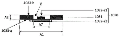
FIGS. 10A-C schematically show a method for producing an Optical Effect Layer (OEL) and show a top view (FIG. 10B) and a cross-sectional view (FIG. 10C) of a magnetic assembly (1030) for producing said OEL, said method comprising using i) a magnetic assembly (1030) to orient at least a part of the plate-like magnetic or magnetizable pigment particles of a coating (1010) made of a coating composition comprising said plate-like magnetic or magnetizable pigment particles, wherein the magnetic assembly (1030) comprises i) a soft-magnetic plate (1031) comprising holes (V) of annular, in particular square, depth of less than 100%, and i) two dipole magnets (1032-a1, 1032a-a2) having their magnetic axes substantially perpendicular to the surface of the soft-magnetic plate (1031) and substantially perpendicular to the surface of a substrate (1020) and having the same magnetic direction, wherein the first dipole magnet (1032-a1) is symmetrically disposed within the annular cavity (V), and the second dipole magnet (1032-a2) is disposed below the soft magnetic plate (1031), below the first dipole magnet (1032-a1), and symmetrically faces the annular cavity (V).
FIG. 10D shows a captured image of an OEL obtained using the method and magnetic assembly shown in FIGS. 10A-C.
11A-C schematically show a method for producing an Optical Effect Layer (OEL) and show a top view (FIG. 11B) and a cross-sectional view (FIG. 11C) of a magnetic assembly (1130) for producing said OEL, said method comprising the use of i) a magnetic assembly (1130) to orient at least a part of the plate-like magnetic or magnetizable pigment particles of a coating (1110) made of a coating composition comprising said plate-like magnetic or magnetizable pigment particles, wherein the magnetic assembly (1130) comprises i) a soft-magnetic plate (1131) comprising ring-shaped, in particular circular, holes (V) having a depth of less than 100%, and ii) a pair of two dipole magnets (1132-B) having their magnetic axes substantially perpendicular to the surface of the soft-magnetic plate (1131) and to the surface of the substrate (1120) and having the same magnetic direction, wherein said two dipole magnets 1132-B) are arranged below the soft-magnetic plate (1131) and in contact with the ring (1131) The cavities (V) are spaced apart.
Fig. 11D shows a photographed image of an OEL obtained by using the method shown in fig. 11A.
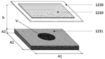
Figures 12A-C schematically illustrate a method for producing an Optical Effect Layer (OEL) and show a top view (figure 12B) and a cross-sectional view (figure 12C) of a magnetic assembly (1230) for producing said OEL, said method comprising using i) a magnetic assembly (1230) to orient at least a portion of the plate-like magnetic or magnetizable pigment particles of a coating layer (1210) made of a coating composition comprising said plate-like magnetic or magnetizable pigment particles, wherein the magnetic assembly (1230) comprises i) a soft magnetic plate (1231) comprising holes (V) of annular, in particular circular, depth of less than 100%, and ii) a pair of two dipole magnets (1232-B) having their magnetic axes substantially perpendicular to the surface of the soft magnetic plate (1231) and substantially perpendicular to the surface of the substrate (1220) and having opposite magnetic directions, wherein the two dipole magnets (1232-b) are arranged below the soft magnetic plate (1231) and spaced apart from the annular cavity (V).
FIG. 12D shows a captured image of an OEL obtained using the method and magnetic assembly shown in FIGS. 12A-C.
FIGS. 13A-C schematically illustrate a method for producing an Optical Effect Layer (OEL) and show a top view (FIG. 13B) and a cross-sectional view (FIG. 13C) of a magnetic assembly (1330) for producing the OEL, the method comprises using i) a magnetic assembly (1330) to orient at least a portion of the plate-like magnetic or magnetizable pigment particles of a coating (1310) made of a coating composition comprising the plate-like magnetic or magnetizable pigment particles, wherein the magnetic assembly (1330) comprises i) a soft magnetic plate (1331) comprising a ring-shaped, in particular circular, cavity (V) with a depth of 100%, and ii) a dipole magnet (1332-a), the magnetic axis of which is substantially perpendicular to the surface of the soft magnetic plate (1331) and substantially perpendicular to the surface of the base material (1320), wherein the dipole magnet (1332-a) is symmetrically disposed within the annular cavity (V).
Fig. 13D shows a captured image of an OEL obtained by using the method and magnetic assembly shown in fig. 13A-C.
Figures 14A-C schematically illustrate a method for producing an Optical Effect Layer (OEL) and show a top view (figure 14B) and a cross-sectional view (figure 14C) of a magnetic assembly (1430) for producing the OEL, the method comprises using i) a magnetic component (1430) to orient at least a portion of plate-like magnetic or magnetizable pigment particles of a coating (1410) made from a coating composition comprising the plate-like magnetic or magnetizable pigment particles, wherein the magnetic assembly (1430) comprises i) a soft magnetic plate (1431) comprising a ring-shaped, in particular circular, cavity (V) with a depth of 100%, and ii) a dipole magnet (1432-a), the magnetic axis of which is substantially perpendicular to the surface of the soft magnetic plate (1431) and substantially perpendicular to the surface of the base material (1420), wherein the dipole magnet (1432-a) symmetrically faces the annular cavity (V).
FIG. 14D shows a captured image of an OEL obtained using the method and magnetic assembly shown in FIGS. 14A-C.
FIGS. 15A-C schematically illustrate a method for producing an Optical Effect Layer (OEL) and show a top view (FIG. 15B) and a cross-sectional view (FIG. 15C) of a magnetic assembly (1530) for producing said OEL, said method comprising the use of i) a magnetic assembly (1530) to orient at least a part of the flake-like magnetic or magnetizable pigment particles of a coating (1510) made of a coating composition comprising said flake-like magnetic or magnetizable pigment particles, wherein the magnetic assembly (1530) comprises i) a soft-magnetic plate (1531) comprising annular, in particular circular, holes (V) having a depth of 100%, and ii) two dipole magnets (1532-a1, 1532a-a2) having their magnetic axes substantially perpendicular to the surface of the soft-magnetic plate (1531) and substantially perpendicular to the surface of the substrate (1520) and having the same magnetic direction, wherein the first dipole magnet (1532-a1) is symmetrically disposed within the annular cavity (V) and the second dipole magnet (1532-a2) is disposed below the first dipole magnet (1532-a1), below the soft magnetic plate (1531) and symmetrically facing the annular cavity (V).
FIG. 15D shows a captured image of an OEL obtained using the method and magnetic assembly shown in FIGS. 15A-C.
Figures 16A-C schematically illustrate a method for producing an Optical Effect Layer (OEL) and show a top view (figure 16B) and a cross-sectional view (figure 16C) of a magnetic assembly (1630) for producing said OEL, said method comprising using i) a magnetic assembly (1630) to orient at least a portion of the plate-like magnetic or magnetizable pigment particles of a coating layer (1610) made of a coating composition comprising said plate-like magnetic or magnetizable pigment particles, wherein the magnetic assembly (1630) comprises i) a soft magnetic plate (1631) comprising holes (V) of annular, in particular circular, depth of less than 100%, and ii) two dipole magnets (1632-a1, 1632a-a2) having their magnetic axes substantially perpendicular to the surface of the soft magnetic plate (1631) and substantially perpendicular to the surface of the substrate (1620) and having opposite magnetic directions, two of the dipole magnets (1632-a1, 1632-a2) are disposed within the annular cavity (V) and spaced apart.
FIG. 16D shows a captured image of an OEL obtained using the method and magnetic assembly shown in FIGS. 16A-C.
Figures 17A-C schematically illustrate a method for producing an Optical Effect Layer (OEL) and show a top view (figure 17B) and a cross-sectional view (figure 17C) of a magnetic assembly (1730) for producing the OEL, the method comprising using i) a magnetic assembly (1730) to orient at least a portion of the plate-like magnetic or magnetizable pigment particles of a coating (1710) made of a coating composition comprising the plate-like magnetic or magnetizable pigment particles, wherein the magnetic assembly (1730) comprises i) a soft magnetic plate (1731) comprising annular, in particular circular, holes (V) having a depth of less than 100%, and ii) two dipole magnets (1732-a1, 1732a-a2) having magnetic axes substantially perpendicular to the surface of the soft magnetic plate (1731) and to the surface of a substrate (1720) and having opposite magnetic directions, wherein two dipole magnets (1732-a1, 1732-a2) are disposed within and spaced apart from the annular cavity (V).
FIG. 17D shows a captured image of an OEL obtained using the method and magnetic assembly shown in FIGS. 17A-C.
Detailed Description
Definition of
The following definitions are set forth to clarify the meaning of terms discussed in the specification and recited in the claims.
As used herein, the indefinite article "a" means one and greater than one, and does not necessarily limit its designated noun to a single one.
The term "at least," as used herein, is intended to define one or more than one, such as one or two or three.
As used herein, the term "about" means that the amount or value in question may be at or near the specified value. In general, the term "about" denoting a particular value is intended to mean a range within ± 5% of that value. As an example, the phrase "about 100" means a range of 100 ± 5, i.e., a range from 95 to 105. In general, when the term "about" is used, it is contemplated that similar results or effects according to the present invention may be obtained within a range of ± 5% of the specified value.
As used herein, the term "and/or" means that all or only one of the elements of the recited group may be present. For example, "a and/or B" shall mean "only a, or only B, or both a and B". In the case of "a only", the term also covers the possibility that B is absent, i.e. "a only, but no B".
The term "comprising" as used herein is intended to be non-exclusive and open-ended. Thus, for example, a coating composition comprising compound a may comprise other compounds than a. However, the term "comprising" also covers as its specific embodiments the more restrictive meanings of "consisting essentially of … …" and "consisting of … …", so that for example "fountain solution comprising A, B and optionally C" may also consist (essentially) of a and B or (essentially) of A, B and C.
The term "optical effect layer" (OEL) as used herein means a coating film or layer comprising oriented, plate-like magnetic or magnetizable pigment particles and a binder, wherein the plate-like magnetic or magnetizable pigment particles are oriented by a magnetic field and wherein the oriented, plate-like magnetic or magnetizable pigment particles are fixed/frozen in their orientation and position (i.e. after hardening/curing) so as to form a magnetically induced image.
The term "magnetic axis" denotes a theoretical line connecting the respective north and south poles of the magnet and extending through the poles. The term does not include any particular magnetic field direction.
The term "magnetic field direction" denotes the direction of the magnetic field vector along the magnetic field lines pointing from the north pole to the south pole outside the magnet (see Handbook of Physics, Springer 2002, pp. 463-464).
The term "coating composition" refers to any composition capable of forming an optical effect layer (EOL) on a solid substrate and which may preferably, but not exclusively, be applied by a printing process. The coating composition comprises the plate-like magnetic or magnetizable pigment particles described herein and a binder described herein.
As used herein, the term "wet" refers to an uncured coating, such as a film coating in which the plate-like magnetic or magnetizable pigment particles are still able to change their position and orientation under the influence of an external force acting on them.
As used herein, the term "indicia" shall mean a discontinuous layer such as a pattern or the like, including without limitation symbols, alphanumeric symbols (alphanumerical symbols), graphics (motifs), letters, words, numbers, logos, and pictures.
The term "hardening … …" is used to denote the following method: wherein the coating composition in a first physical state, which is not yet hardened (i.e. wetted), increases in viscosity, thereby transforming it into a second physical state, i.e. hardened or solid state, wherein the plate-like magnetic or magnetizable pigment particles are fixed/frozen in their current position and orientation and are no longer able to move or rotate.
The term "security document" refers to a document that is typically protected from counterfeiting or fraud by at least one security feature. Examples of security documents include, without limitation, documents of value and commercial goods of value.
The term "security feature" is used to denote an image, pattern or graphic element that may be used for authentication purposes.
Where the present specification refers to "preferred" embodiments/features, combinations of these "preferred" embodiments/features should also be considered disclosed, as long as such combinations of "preferred" embodiments/features are technically meaningful.
The present invention provides a magnetic assembly (x30) and method for producing an Optical Effect Layer (OEL). The Optical Effect Layers (OELs) thus obtained provide the impression of more than one body having a shape that changes when tilting the optical effect layers and/or moves when tilting the optical effect layers.
According to one embodiment, the present invention provides a magnetic assembly (x30) and a method for producing an Optical Effect Layer (OEL) exhibiting one or more labels. An Optical Effect Layer (OEL) exhibiting more than one mark refers to a layer in which the orientation of the plate-like magnetic or magnetizable pigment particles described herein within the OEL allows the more than one mark to be observed. The indicia may be in any form including, without limitation, symbols, alphanumeric symbols, graphics, letters, words, numbers, logos, and pictures. More than one marker may have a circular, oval, elliptical, triangular, square, rectangular or any polygonal shape. Examples of shapes include circular or circular, rectangular or square (with or without rounded corners), triangular (with or without rounded corners), pentagonal (with or without rounded corners), hexagonal (with or without rounded corners), heptagonal (with or without rounded corners), octagonal (with or without rounded corners), polygonal (with or without rounded corners), cardioid, star, moon, etc.
The invention provides a method for producing an Optical Effect Layer (OEL), in particular an Optical Effect Layer (OEL) exhibiting one or more markings, in an as yet unhardened (i.e. wet or liquid) coating made of a coating composition comprising plate-like magnetic or magnetizable pigment particles and a binder material on a substrate (x20) by obtaining a magnetic orientation of the pigment particles by: the coating (x10) was exposed to the magnetic field of the magnetic assembly (x30) described herein.
The magnetic assembly (x30) described herein is mounted on the Transfer Device (TD) described herein, and the magnetic assembly (x30) described herein comprises i) a soft magnetic plate (x31) made from the composite described herein and comprising one or more voids (V) described herein, and ii) one or more dipole magnets (x32-a) described herein and disposed within and/or facing the one or more voids (V), and/or one or more pairs of dipole magnets (x32-b) described herein and disposed below and spaced apart from the one or more voids (V) of the soft magnetic plate (x 31).
The invention further provides a Transfer Device (TD) as described herein, and a printing apparatus comprising a Transfer Device (TD) as described herein. The Transfer Device (TD) described herein comprises at least one of the magnetic assemblies (x30) described herein, wherein said at least one of the magnetic assemblies (x30) described herein is mounted on said Transfer Device (TD) described herein. The Transfer Device (TD) described herein may be a rotating magnetic alignment cylinder (RMC) or a Linear Magnetic Transfer Device (LMTD), such as a linear guide. Preferably, the Transfer Device (TD) described herein is a rotating magnetic alignment cylinder (RMC). Preferably, the Transfer Device (TD) is a Rotating Magnetic Cylinder (RMC), wherein said at least one of said herein described magnetic assemblies (x30) is mounted in a circumferential groove or a transverse groove of the Rotating Magnetic Cylinder (RMC). In one embodiment, the Rotating Magnetic Cylinder (RMC) is part of a rotary, sheet-fed (sheet-fed) or web-fed (web-fed) industrial printing press operating at high printing speeds in a continuous manner.
A Transfer Device (TD), preferably a Rotating Magnetic Cylinder (RMC), comprising at least one of the herein described magnetic assemblies (x30) mounted thereon, is intended for use in, or in conjunction with, or as part of a printing or coating apparatus. In one embodiment, the Transfer Device (TD) is a Rotating Magnetic Cylinder (RMC), such as those described herein.
A printing apparatus comprising a Transfer Device (TD) as described herein, preferably a Rotating Magnetic Cylinder (RMC) as described herein, and comprising at least one of the magnetic assemblies (x30) as described herein, may comprise a substrate feeder for feeding a substrate such as those described herein. In an embodiment of the printing apparatus comprising the Transfer Device (TD) described herein, preferably the Rotating Magnetic Cylinder (RMC) described herein, the substrate is fed by a substrate feeder in the form of a sheet feed (sheet) or a web (web).
A printing apparatus comprising a Transfer Device (TD) as described herein, preferably a Rotating Magnetic Cylinder (RMC) as described herein, and comprising at least one of the magnetic assemblies (x30) as described herein may comprise a substrate guiding system. As used herein, "substrate guide system" refers to an assembly that maintains a substrate (x10) bearing a coating (x10) in intimate contact with a Transfer Device (TD) as described herein, preferably a Rotating Magnetic Cylinder (RMC) as described herein. The substrate guiding system may be a gripper and/or a vacuum system. In particular, the gripper may be used for the purpose of holding the leading edge of the substrate (x10) and allowing transfer of (x10) from one portion of the printer to the next, and the vacuum system may be used to draw the surface of (x10) against the surface of the Transfer Device (TD) described herein, preferably against the surface of the Rotating Magnetic Cylinder (RMC) described herein, and to maintain it in firm alignment therewith. In addition to or instead of the gripper and/or vacuum system, the substrate guiding system may comprise other pieces of substrate guiding apparatus including, without limitation, a roller or a set of rollers, a brush or a set of brushes, a belt and/or a set of belts, a blade or a set of blades, or a spring or a set of springs.
A printing apparatus comprising a Transfer Device (TD) as described herein, preferably a Rotating Magnetic Cylinder (RMC) as described herein, and comprising at least one of the magnetic assemblies (x30) as described herein, may comprise a coating or printing unit for applying a coating composition comprising plate-like magnetic or magnetizable pigment particles as described herein on a substrate (x10) as described herein, thereby forming a coating layer (x20) as described herein.
A printing apparatus comprising a Transfer Device (TD) as described herein, preferably a Rotating Magnetic Cylinder (RMC) as described herein, and comprising at least one of the magnetic assemblies (x30) as described herein, may comprise a hardening unit (x50), preferably a curing unit, for at least partially hardening the coating (x20) comprising plate-like magnetic or magnetizable pigment particles that have been magnetically oriented by the magnetic field of the magnetic assembly (x30) as described herein, thereby fixing the orientation and position of the plate-like magnetic or magnetizable pigment particles, thereby producing the Optical Effect Layer (OEL).
The soft magnetic sheet (x31) described herein is characterized by an upper surface, wherein the upper surface consists of the surface of the substrate (x20) on which the carrier coating (x10) is to be placed in direct contact or indirect contact. For example, as shown in fig. 3A and 4A, the upper surface (dotted line) of the soft magnetic sheet (x31) including one or more voids (V) described herein is composed of the upper surface of the sheet itself. Alternatively and when the soft magnetic sheet (x31) described herein includes non-magnetic holders or spacers (x33) such as those described below on its upper surface and covers one or more of the voids (V) described herein, the upper surface of the soft magnetic sheet (x31) is considered to be the upper surface of the non-magnetic holders or spacers (x 33).
The soft magnetic sheet (x31) includes one or more holes (V) described herein. When more than one cavity (V) is included in the soft magnetic sheet (x31) described herein, the cavities (V) may have the same shape or may have different shapes.
Fig. 1 schematically depicts a view of a soft magnetic plate (131) having a thickness (T) and comprising voids (V), in particular annular voids (V) (heart-shaped). In the context of the present invention, the term "hole" means a recess (see fig. 2A) in the soft magnetic plate or a hole or channel (see fig. 2B) that runs through the soft magnetic plate and connects its two sides.
Fig. 2A-B schematically depict a cross section of a soft magnetic plate (231) comprising holes (V), wherein the holes (V) have a depth (D). According to one embodiment and as shown for example in fig. 2A, the soft magnetic sheet (231) described herein comprises one or more holes (V) with a depth of less than 100%, i.e. in the form of recesses. According to another embodiment and as shown for example in fig. 2B, the soft magnetic plate (231) described herein comprises one or more holes (V) with a depth of 100%, i.e. one or more holes (V) are in the form of holes or channels running through the soft magnetic plate (231) and connecting its two sides.
The soft magnetic sheet (x31) described herein is made of a composite including spherical soft magnetic particles dispersed in a non-magnetic material in an amount of about 25 to about 95 wt%, preferably about 50 to about 90 wt%, based on the total weight of one or more soft magnetic sheets.
The spherical soft magnetic particles described herein are made of one or more soft magnetic materials preferably selected from the group consisting of iron (especially iron pentacarbonyl, also known as iron carbonyl), nickel (especially nickel tetracarbonyl, also known as nickel carbonyl), cobalt, soft magnetic ferrites (e.g., manganese-zinc ferrite and nickel-zinc ferrite), soft magnetic oxides (e.g., oxides of manganese, iron, cobalt and nickel), and combinations thereof, more preferably from the group consisting of iron carbonyl, nickel carbonyl, cobalt, and combinations thereof.
The spherical soft magnetic particles described herein preferably have an average particle diameter (d)50) In about 0.1 μm &Between about 1000 μm, more preferably between about 0.5 μm and about 100 μm, still more preferably between about 1 μm and about 20 μm, and even more preferably between about 2 μm and about 10 μm, d50Measured by laser diffraction using, for example, a microtrac x100 laser particle size analyzer.
The soft magnetic sheet (x31) described herein is made of the composite described herein, wherein the composite comprises spherical soft magnetic particles described herein dispersed in a non-magnetic material. Suitable nonmagnetic materials include, without limitation, polymeric materials that form a matrix for dispersed soft magnetic particles. The polymeric matrix forming material may be or include one or more thermoplastic materials or one or more thermoset materials. Suitable thermoplastic materials include, without limitation, polyamides, copolyamides, polyphthalamides, polyolefins, polyesters, polytetrafluoroethylenes, polyacrylates, polymethacrylates (e.g., PMMA), polyimides, polyetherimides, polyetheretherketones, polyaryletherketones, polyphenylene sulfides, liquid crystal polymers, polycarbonates, and mixtures thereof. Suitable thermosetting materials include, without limitation, epoxy resins, phenolic resins, polyimide resins, polyester resins, silicone resins, and mixtures thereof. One or more soft magnetic sheets (x31) described herein are made from a composite comprising from about 5 wt% to about 75 wt%, preferably from about 10 wt% to about 50 wt%, of a non-magnetic material described herein, the weight percentages being based on the total weight of the one or more soft magnetic sheets.
The soft magnetic sheet (x31) described herein may further include one or more additives such as hardeners, dispersants, plasticizers, fillers/extenders (extenders) and defoamers.
The one or more soft magnetic sheets (x31) described herein preferably have a thickness of at least about 0.5mm, more preferably at least about 1mm, and still more preferably between about 1mm and about 5 mm. As described above and shown in fig. 1, the thickness (T) of the soft magnetic plate (x31) including one or more holes described herein means the thickness of the region of the soft magnetic plate (x31) that does not have one or more holes (V).
The soft magnetic plates described herein (x31) may additionally be surface treated to promote contact with the substrate (x20) bearing the coating described herein (x10) to reduce friction and/or wear and/or electrostatic charging in high speed printing applications.
According to a preferred embodiment, the soft magnetic plates (x31) described herein are curved so as to be usable in or on the Rotating Magnetic Cylinder (RMC) described herein. Preferably, the soft magnetic plate (x31) has a curved surface with a substantially similar curvature as the outer surface of the rotating magnetic cylinder described herein, such that the surface of the substrate (x20) comprising the coating (x10) comprising the plate-like magnetic or magnetizable pigment particles described herein is not negatively affected.
The herein described one or more holes (V) of the herein described soft magnetic plate (x31) are designed to receive the herein described one or more dipole magnets (x32-a), i.e. they allow the herein described one or more dipole magnets (x32-a) to be incorporated into the soft magnetic plate (x31), or they allow the herein described one or more dipole magnets (x32-a) to be incorporated into the one or more holes (V) below the soft magnetic plate (x31) and facing the soft magnetic plate (x 31).
Preferably, one or more cavities (V) described herein have the shape of indicia, including without limitation symbols, alphanumeric symbols, graphics, letters, words, numbers, logos, and pictures. The one or more cavities (V) may have a circular, oval, elliptical, triangular, square, rectangular or any polygonal shape. Examples of shapes include circular or circular, rectangular or square (with or without rounded corners), triangular (with or without rounded corners), pentagonal (with or without rounded corners), hexagonal (with or without rounded corners), heptagonal (with or without rounded corners), octagonal (with or without rounded corners), polygonal (with or without rounded corners), cardioid, star, moon, etc.
According to one embodiment, the soft magnetic sheet (x31) described herein comprises one or more voids (V) described herein, wherein the one or more voids (V), in particular the voids having a depth of 100%, may be filled with a non-magnetic material comprising a polymeric binder such as those described below and optionally a filler. The soft magnetic sheet (x31) described herein comprising one or more voids (V) described herein may be disposed on a non-magnetic holder or spacer (x33), such as a non-magnetic metal sheet, which may be made of one of the polymer matrix materials described herein. Typically, the non-magnetic holder or spacer (x33), such as a non-magnetic metal plate, may be made of one of the polymer matrix materials described herein. For example, a soft magnetic plate (x31) including one or more holes (V) described herein and having a depth of 100% may be disposed on the non-magnetic holder or spacer (x 33). The one or more voids (V) recited herein may be covered by non-magnetic retainers or spacers (x33) such as those described below.
The one or more cavities (V) of the soft magnetic sheet (x31) described herein can be produced by any cutting or engraving method known in the art including, without limitation, casting, molding, hand engraving, or an ablation tool selected from the group consisting of a mechanical ablation tool, a gas or liquid jet ablation tool via chemical etching, electrochemical etching, and a laser ablation tool (e.g., CO)2-Nd-YAG or excimer laser). Preferably, more than one cavity (V) of the soft magnetic sheet (x31) described herein is produced and processed like any other polymeric material. Techniques known in the art may be used, including 3D printing, stack molding, compression molding, resin transfer molding, or injection molding. After shaping, standard curing procedures may be applied, such as cooling (when using thermoplastic polymers) or curing at elevated or low temperatures (when using thermosetting polymers). Another method for obtaining more than one soft magnetic composite sheet (x31) described herein is to use standard tools to remove a portion of them to obtain the required voids (V) to make the plastic part. In particular, mechanical ablation tools may be advantageously used.
The distance (h) between the upper surface of the soft magnetic plate (x31) of the magnetic assembly (x30) described herein and the substrate (x20) bearing the coating (x10) is adjusted and selected so as to obtain the desired Optical Effect Layer (OEL). It is particularly preferable to use a soft magnetic sheet (x31) in which the distance between the upper surface and the base material (x20) is near zero or zero.
During the production of the Optical Effect Layers (OEL) described herein, the substrate (x20) bearing the coating (x10) is exposed to the magnetic field of the magnetic assembly (x30) described herein, orienting the plate-like magnetic or magnetizable pigment particles while the coating/composition is still in a wet (i.e. not yet hardened) state.
In addition to the soft magnetic plate (x31) described herein, the magnetic assembly (x30) described herein comprises one or more dipole magnets (x32-a) described herein and/or one or more pairs of two dipole magnets (x32-b) described herein.
The one or more dipole magnets (x32-a) and the one or more pairs of two dipole magnets (x32-b) described herein are preferably independently made of a high-coercivity material (also referred to as a ferromagnetic material). Suitable high coercivity materials are materials having a coercivity field value of at least 50kA/m, preferably at least 200kA/m, more preferably at least 1000kA/m, even more preferably at least 1700 kA/m. They are preferably made of more than one sintered or polymer-bonded magnetic material selected from the group consisting of: alnicos, such as Alnico 5(R1-1-1), Alnico 5 DG (R1-1-2), Alnico 5-7(R1-1-3), Alnico 6(R1-1-4), Alnico 8(R1-1-5), Alnico 8 HC (R1-1-7), and Alnico 9 (R1-1-6); formula MFe12O19Hexagonal ferrite (e.g., strontium hexaferrite (SrO 6 Fe)2O3) Or barium hexaferrite (BaO 6 Fe)2O3) MFe) of the formula2O4Hard ferrites (e.g., cobalt ferrites (CoFe)2O4) Or magnetite (Fe)3O4) M is divalent metal ion), ceramic 8 (SI-1-5); selected from the group consisting of RECo5(RE is Sm or Pr), RE2TM17(RE=Sm、TM=Fe、Cu、Co、Zr、Hf)、RE2TM14B (RE ═ Nd, Pr, Dy, TM ═ Fe, Co) rare earth magnetic materials; fe. Anisotropy of Cr and CoGold; a material selected from the group of PtCo, MnAlC, RE cobalt 5/16, RE cobalt 14. Preferably, the high coercivity material of the one or more dipole magnets (x32-a) described herein and the one or more pair of two dipole magnets (x32-b) described herein is independently selected from the group consisting of rare earth magnetic materials, and more preferably from the group consisting of Nd2Fe4B and SmCo5Group (d) of (a). It is particularly preferred to include a permanent magnetic filler such as strontium-hexaferrite (SrFe) in a plastic or rubber-like matrix12O19) Or neodymium-iron-boron (Nd)2Fe14B) Powdered permanent magnet composite material which can be easily processed.
The one or more dipole magnets (x32-a) described herein are disposed within (see, e.g., fig. 3A, 3B, 4A, and 4B) or face (see, e.g., fig. 3C and 4C) the one or more cavities (V). The one or more dipole magnets (x32-a) described herein may be symmetrically or asymmetrically disposed within and may symmetrically or asymmetrically face the one or more cavities (V) described herein.
When more than one dipole magnet (x32-a) is used instead of one dipole magnet (x32-a), the more than one dipole magnets (x32-a) may be disposed within more than one cavity (V), may all be disposed facing more than one cavity (V), or at least one of the more than one dipole magnets (x32-a) may be disposed within more than one cavity (V), and at least one other may be disposed facing more than one cavity (V) (see, e.g., fig. 3D and 4D).
When more than one dipole magnet (x32-a) is used instead of one dipole magnet (x32-a), the more than one dipole magnets (x32-a) are preferably placed on top of each other. The more than one dipole magnet (x32-a) may be the same or different in shape. The dimensions of the upper surfaces (diameters in the case of cylindrical dipole magnets) of the more than one dipole magnet (x32-a) may be the same or different. The thickness of the more than one dipole magnet (x32-a) is the same or different.
According to one embodiment, the magnetic assembly (x30) described herein comprises a soft magnetic plate (x31) comprising more than one cavity (V) having a depth of less than 100% as those described herein, and comprising more than one dipole magnet (x32-a), wherein the more than one dipole magnets (x32-a) are placed above each other and separated by the soft magnetic plate (x31) in the region of the more than one cavity (V), i.e. one of the dipole magnets (x32-a) is arranged within the more than one cavity (V) and at least another of the dipole magnets (x32-a) is arranged facing the more than one cavity (V) (see e.g. fig. 3D). According to another embodiment, the soft magnetic plate (x31) comprises more than one cavity (V) with a depth of 100% comprising more than one dipole magnet (x32-a), wherein the more than one dipole magnets (x32-a) are placed above each other, i.e. one of the dipole magnets (x32-a) is arranged within the more than one cavity (V) and at least another one of the dipole magnets (x32-a) is arranged below the soft magnetic plate (x31) and facing the more than one cavity (V) (see e.g. fig. 4D).
When more than one dipole magnet (x32-a) is used instead of one dipole magnet (x32-a), the more than one dipole magnets (x32-a) may be placed on top of each other (see, e.g., fig. 3D and 4D) or may be set aside from each other (see fig. 3E and 3F). The more than one dipole magnet (x32-a) described herein is preferably all disposed within a single cavity (V), such as those described herein, or all disposed facing a single cavity (V), such as those described herein, more preferably, and as shown in fig. 3E-F and 4D, the more than one dipole magnet (x32-a) described herein is preferably all disposed within a single cavity (V). The more than one dipole magnets (x32-a) may be the same or different in shape. The thickness of the more than one dipole magnet (x32-a1, x32-a2, etc.) may be the same or different. More than one dipole magnet (x32-a) described herein and disposed within a single cavity (V) may be placed above each other (see fig. 4D). The more than one dipole magnets (x32-a) described herein and disposed within a single void (V) may be adjacent to each other (see fig. 3F) or may be laterally spaced apart (see fig. 3F), wherein the more than one dipole magnets (x32-a) preferably have opposite magnetic directions.
According to one embodiment, the magnetic axis of each of the one or more dipole magnets (x32-a) described herein is substantially perpendicular to the surface of the base material (x20) and substantially perpendicular to the surface of the soft magnetic sheet (x 31). Preferably, all of the one or more dipole magnets (x32-a) have the same magnetic direction.
The pair or more of the dipole magnets (x32-b) described herein are disposed below the soft magnetic plate (x31) and spaced apart from the one or more voids (V) (or in other words, disposed below the soft magnetic plate (x31) at opposite sides of the one or more voids (V)). Preferably, the herein described pair or more of two dipole magnets (x32-b) are arranged below the soft magnetic plate (x31), spaced from the one or more cavities (V), and their side surfaces are flush with the outer surface of the one or more cavities (V) (see e.g. fig. 5-6).
The two or more dipole magnets (x32-b) described herein preferably have magnetic axes substantially perpendicular to the surface of the base material (x20) and substantially perpendicular to the surface of the soft magnetic plate (x31), the magnetic axes having the same magnetic direction or opposite magnetic directions.
According to one embodiment, the magnetic assembly (x30) described herein comprises one or more dipole magnets (x32-a) described herein. According to another embodiment, the magnetic assembly described herein (x30) comprises more than one pair of two dipole magnets (x32-b) described herein. According to another embodiment, the magnetic assembly described herein (x30) comprises one or more dipole magnets described herein (x32-a) and one or more pairs of dipole magnets described herein (x 32-b).
For embodiments in which the magnetic assembly (x30) described herein comprises one or more dipole magnets (x32-a) described herein and one or more pairs of two dipole magnets (x32-b) described herein, the one or more dipole magnets (x32-a) preferably have their magnetic axes substantially perpendicular to the surface of the base material (x20) and substantially perpendicular to the surface of the soft magnetic plate (x31), and all of the one or more dipole magnets (x32-a) have the same magnetic direction, and the one or more pairs of the two dipole magnets (x32-b) described herein preferably have their magnetic axes substantially perpendicular to the surface of the base material (x20) and substantially perpendicular to the surface of the soft magnetic plate (x31), the magnetic axes having the same magnetic direction or opposite magnetic directions (see fig. 5C-D and 6C-D).
According to one embodiment and as shown, for example, in fig. 3A-B, a magnetic assembly (x30) described herein comprises i) a soft magnetic plate (x31) described herein comprising one or more cavities (V) described herein having a depth of less than 100%, and ii) one or more dipole magnets (x32a) described herein disposed within the one or more cavities (V) with all their magnetic axes substantially perpendicular to the surface of the substrate (x20) and substantially perpendicular to the surface of the soft magnetic plate (x31) and having the same magnetic direction, wherein the upper surface of the one or more dipole magnets (x32-a) is flush with the upper surface of the soft magnetic plate (x31) (see, for example, fig. 3A) or is located below the upper surface of the soft magnetic plate (x31) (see, for example, fig. 3B).
According to one embodiment and as shown, for example, in fig. 3C, a magnetic assembly (x30) described herein comprises i) a soft magnetic plate (x31) described herein comprising one or more holes (V) described herein having a depth of less than 100%, and ii) one or more dipole magnets (x32a) described herein facing the one or more holes (V) with all their magnetic axes substantially perpendicular to the surface of the base material (x20) and substantially perpendicular to the surface of the soft magnetic plate (x31) and having the same magnetic direction, wherein the upper surface of at least one of the one or more dipole magnets (x32-a) is flush with the lower surface of the soft magnetic plate (x31) at the region of the one or more holes (V).
According to one embodiment and as shown, for example, in fig. 3D, a magnetic assembly (x30) described herein comprises i) a soft magnetic plate (x31) described herein comprising one or more cavities (V) described herein having a depth of less than 100%, and ii) one or more dipole magnets (x32-a) disposed within the one or more cavities (V) and one or more dipole magnets (x32a) described herein facing the one or more cavities (V), all of the magnets (x32-a and (x32-b) having their magnetic axes substantially perpendicular to the surface of the base material (x20) and substantially perpendicular to the surface of the soft magnetic plate (x31) and having the same magnetic direction, wherein the upper surface of at least one of the one or more dipole magnets (x32-a) is flush with the upper surface of the soft magnetic plate (x31) or is located below the upper surface of the soft magnetic plate (x31) (see fig. 3D), and the upper surface of at least another one of the one or more dipole magnets (x32-a) is flush with the lower surface of the soft magnetic plate (x31) at the region of the one or more voids (V) (see fig. 3D).
According to one embodiment and as shown, for example, in fig. 4A-B, a magnetic assembly (x30) described herein comprises i) a soft magnetic plate (x31) described herein, comprising one or more cavities (V) described herein having a depth of 100%, and ii) one or more dipole magnets (x32a) described herein, which are arranged in more than one cavity (V) with all their magnetic axes substantially perpendicular to the surface of the substrate (x20) and substantially perpendicular to the surface of the soft magnetic sheet (x31) and having the same magnetic direction, wherein the upper surface of the one or more dipole magnets (x32-a) is flush with the upper surface of the soft magnetic plate (x31) (see, e.g., fig. 4A) or is located below the upper surface of the soft magnetic plate (x31) (see, e.g., fig. 4B), preferably wherein the upper surface of at least one of the one or more dipole magnets (x32-a) is flush with the upper surface of the soft magnetic plate (x 31).
According to one embodiment and as shown for example in fig. 4C, the magnetic assembly described herein (x30) comprises i) a soft magnetic plate described herein (x31) comprising one or more holes (V) described herein with a depth of 100%, and ii) one or more dipole magnets described herein (x32a) facing the one or more holes (V) with all their magnetic axes substantially perpendicular to the surface of the base material (x20) and substantially perpendicular to the surface of the soft magnetic plate (x31) and having the same magnetic direction, wherein the upper surface of at least one of the one or more dipole magnets (x32-a) is flush with the lower surface of the soft magnetic plate (x31) at the region of the one or more holes (V).
According to one embodiment and as shown for example in fig. 4D, the magnetic assembly (x30) described herein comprises i) a soft magnetic plate (x31) described herein comprising one or more holes (V) described herein having a depth of 100%, and ii) one or more dipole magnets (x32-a) disposed within the one or more holes (V) and one or more dipole magnets (x32a) described herein facing the one or more holes (V), all of the magnets (x32-a and (x32-b) having their magnetic axes substantially perpendicular to the surface of the base (x20) and substantially perpendicular to the surface of the soft magnetic plate (x31) and having the same magnetic direction, wherein the upper surface of at least one of the one or more dipole magnets (x32-a) is flush with the upper surface of the soft magnetic plate (x31) or below the upper surface of the soft magnetic plate (x31) (see for example fig. 4D), and the upper surface of at least another one of the one or more dipole magnets (x32-a) is flush with the lower surface of the soft magnetic plate (x31) at the region of the one or more voids (V) (see fig. 4D).
According to one embodiment and as shown, for example, in fig. 5A-B, a magnetic assembly (x30) described herein comprises i) a soft magnetic plate (x31) described herein, comprising one or more cavities (V) described herein having a depth of less than 100%, and ii) one or more pairs of two dipole magnets (x32b) described herein, which are arranged below the soft magnetic plate (x31) and are spaced apart from one or more cavities (V), all of whose magnetic axes are substantially perpendicular to the surface of the substrate (x20) and substantially perpendicular to the surface of the soft magnetic plate (x31) and have the same magnetic direction (FIG. 5A) or have opposite magnetic directions (FIG. 5B), wherein the upper surfaces of more than one pair of two dipole magnets (x32-b) are preferably flush with the lower surface of the soft magnetic plate (x31), and preferably their side surfaces are flush with the outer surface of the annular cavity (V) (see fig. 5A-B).
According to another embodiment and as shown, for example, in fig. 6A-B, a magnetic assembly (x30) described herein comprises i) a soft magnetic plate (x31) described herein, comprising one or more cavities (V) described herein having a depth of 100%, and ii) one or more pairs of two dipole magnets (x32b) described herein, which are arranged below the soft magnetic plate (x31) and are spaced apart from one or more cavities (V), all of whose magnetic axes are substantially perpendicular to the surface of the substrate (x20) and substantially perpendicular to the surface of the soft magnetic plate (x31) and have the same magnetic direction (FIG. 6A) or have opposite magnetic directions (FIG. 6B), wherein the upper surfaces of more than one pair of two dipole magnets (x32-b) are preferably flush with the lower surface of the soft magnetic plate (x31), and preferably their side surfaces are flush with the outer surface of the annular cavity (V) (see fig. 6A-B).
According to another embodiment and as shown, for example, in fig. 5C, a magnetic assembly (x30) described herein comprises i) a soft magnetic plate (x31) described herein comprising one or more holes (V) described herein having a depth of less than 100%, and ii) one dipole magnet (x32-a) disposed facing the one or more holes (V) and having a magnetic axis substantially parallel to the surface of the substrate (x20) and substantially parallel to the surface of the soft magnetic plate (x31), and a pair of or more dipole magnets (x32b) described herein disposed below the soft magnetic plate (x31) and spaced apart from the one or more holes (V), the magnetic axes of the pair of or more dipole magnets (x32-b) being substantially perpendicular to the surface of the substrate (x20) and substantially perpendicular to the surface of the soft magnetic plate (x31) and having the same magnetic direction or having opposite magnetic directions (fig. 5C), wherein the upper surface of the dipole magnet (x32-a) and the upper surfaces of the two or more pairs of dipole magnets (x32-b) are preferably flush with the lower surface of the soft magnetic plate (x31), and wherein the side surfaces of the two or more pairs of dipole magnets (x32-b) are preferably flush with the outer surface of the ring-shaped cavity (V) (see fig. 5C).
According to another embodiment and as shown, for example, in fig. 5D, the magnetic assembly (x30) described herein comprises i) a soft magnetic plate (x31) described herein comprising one or more holes (V) described herein having a depth of less than 100%, and ii) more than one, in particular two, dipole magnets (x32-a1, x32-a2) arranged facing the one or more holes (V) and having all their magnetic axes substantially parallel to the surface of the substrate (x20) and substantially parallel to the surface of the soft magnetic plate (x31), and a pair of or more than two dipole magnets (x32b) described herein arranged below the soft magnetic plate (x31) and spaced apart from the one or more holes (V), the magnetic axes of the pair of or more than two dipole magnets (x32-b) being substantially perpendicular to the surface of the substrate (x20) and substantially perpendicular to the surface of the soft magnetic plate (x31) and having the same magnetic direction or having opposite magnetic directions (fig. 5D) Wherein the upper surface of more than one dipole magnet (x32-a1, x32-a2) and the upper surface of the two or more pairs of dipole magnets (x32-b) are preferably flush with the lower surface of the soft magnetic plate (x31), and wherein the side surfaces of the two or more pairs of dipole magnets (x32-b) are preferably flush with the outer surface of the ring-shaped cavity (V) (see fig. 5D). Preferably, more than one dipole magnet (x32-a1, x32-a2) are laterally adjacent to each other.
According to another embodiment and as shown, for example, in fig. 6C, a magnetic assembly (x30) described herein comprises i) a soft magnetic plate (x31) described herein comprising one or more holes (V) described herein having a depth of 100%, and ii) one or more dipole magnets (x32-a) disposed facing the one or more holes (V) and having a magnetic axis substantially parallel to the surface of the substrate (x20) and substantially parallel to the surface of the soft magnetic plate (x31), and a pair of or more dipole magnets (x32b) described herein disposed below the soft magnetic plate (x31) and spaced apart from the one or more holes (V), the magnetic axes of the pair of or more dipole magnets (x32-b) being substantially perpendicular to the surface of the soft magnetic substrate (x20) and substantially perpendicular to the surface of the soft magnetic plate (x31) and having the same magnetic direction or having opposite magnetic directions (fig. 6C), wherein the upper surface of the dipole magnet (x32-a) is preferably flush with the lower surface of the soft magnetic plate (x31) at the region of the one or more cavities (V), and the upper surfaces of the one or more pairs of two dipole magnets (x32-b) are preferably flush with the lower surface of the soft magnetic plate (x31), and preferably their side surfaces are flush with the outer surface of the annular cavity (V) (see fig. 6C).
According to another embodiment and as shown, for example, in fig. 6D, the magnetic assembly (x30) described herein comprises i) a soft magnetic plate (x31) described herein comprising one or more holes (V) described herein having a depth of less than 100%, and ii) more than one, in particular two, dipole magnets (x32-a1, x32-a2) arranged facing the one or more holes (V) and having all their magnetic axes substantially parallel to the surface of the substrate (x20) and substantially parallel to the surface of the soft magnetic plate (x31), and a pair of or more than two dipole magnets (x32b) described herein arranged below the soft magnetic plate (x31) and spaced apart from the one or more holes (V), the magnetic axes of the pair of or more than two dipole magnets (x32-b) being substantially perpendicular to the surface of the substrate (x20) and substantially perpendicular to the surface of the soft magnetic plate (x31) and having the same magnetic direction or having opposite magnetic directions (fig. 5D) Wherein the upper surface of more than one dipole magnet (x32-a1, x32-a2) and the upper surface of more than one pair of two dipole magnets (x32-b) are preferably flush with the lower surface of the soft magnetic plate (x31), and wherein the more than one pair of two dipole magnets (x32-b) have preferably their side surfaces flush with the outer surface of the ring-shaped cavity (V) (see fig. 6D). Preferably, more than one dipole magnet (x32-a1, x32-a2) are laterally adjacent to each other.
The present invention further provides a process for producing an Optical Effect Layer (OEL) as described herein on a substrate (x20) such as those described herein, said process comprising the steps of:
a) applying a coating composition comprising plate-like magnetic or magnetizable pigment particles and a binder material as described herein on a surface of a substrate (x20) to form a coating (x10) on the substrate (x20), the coating composition being in a first liquid state;
b) exposing the coating (x10) to the magnetic field of a magnetic assembly (x30) described herein; and is
c) The coating composition is allowed to harden to a second state, thereby fixing the platelet-shaped magnetic or magnetizable pigment particles in the position and orientation they adopt.
The method described herein comprises the step a) of applying a coating composition comprising the herein described platy magnetic or magnetizable pigment particles on the surface of the herein described substrate (x20) to form a coating layer, the coating composition being in a first physical state, which enables application as a layer and in an as yet unhardened (i.e. wet) state in which the platy magnetic or magnetizable pigment particles can move and rotate within the binder material. Because the coating compositions described herein are to be disposed on a substrate surface, it is necessary that the coating composition comprising at least the binder material described herein and the platy magnetic or magnetizable pigment particles be in a form such that it can be handled in the desired printing or coating apparatus. Preferably, said step a) is performed by a printing method, preferably selected from the group consisting of screen printing (screen printing), rotogravure printing, flexographic printing, ink jet printing and intaglio printing (also known in the art as engraved copperplate printing and engraved steel die printing), more preferably selected from the group consisting of screen printing, rotogravure printing and flexographic printing.
Screen Printing (also known in The art as screen Printing) is a stencil process (steel process) in which ink is transferred to a surface through a stencil supported by a fine fabric web of filament fabric, monofilaments or multifilaments made of synthetic fibers such as polyamide or polyester or metal wires tightly stretched over a frame made of, for example, wood or metal such as aluminum or stainless steel, optionally, The screen Printing web may be a porous metal foil such as stainless steel foil that is chemically etched, laser etched, or electroplated, The pores of The web block in The non-image areas and remain open in The image areas, The image carrier is referred to as a screen, which may be flat or rotary, screen Printing is further described in, for example, The Printing industry, r.h. leave and r.j.pierce, spring Edition, 5 th Edition, pages 58-62 and Printing Technology, adams and p.a. dolin, delmr Thomson Learning, 5 th edition, page 293-328.
Rotogravure printing (also known in the art as intaglio printing) is a printing process in which image elements are engraved into the surface of a cylinder. The non-image areas are at a constant original level. Prior to printing, the entire printing plate (non-printing and printing elements) is inked and flooded (flood). The ink is removed from the non-image areas by a wipe or squeegee prior to printing, so that the ink remains only in the cells. The image is transferred from the chamber to the substrate by a pressure typically in the range of 2-4 bar and by adhesion between the substrate and the ink. The term rotogravure printing does not cover intaglio printing processes (also known in the art as engraved steel dies or copperplate printing processes) that rely on, for example, different kinds of inks. More details are provided in The Handbook of print media ", Helmut Kipphan, Springer Edition, page 48 and The Printing in manual, R.H.Leach and R.J.Pierce, Springer Edition, 5 th Edition, pages 42-51.
Flexographic printing preferably uses units with doctor blades (dod blades), preferably housed (chambered) doctor blades, anilox rollers (anilox rollers) and plate cylinders (plate cylinder). The anilox roller advantageously has cells whose volume and/or density determine the ink application speed. The doctor blade bears against the anilox roller and at the same time scrapes off excess ink. Anilox rollers transfer ink to a plate cylinder, which ultimately transfers the ink to a substrate. A particular design may be achieved using a designed photopolymer plate. The plate cylinder may be made of polymeric or elastomeric material. The polymer is used primarily as a photopolymer in the plate and sometimes as a seamless coating on the sleeve. Photopolymer plates are made of photosensitive polymers that are hardened by Ultraviolet (UV) light. The photopolymer plate is cut to the required dimensions and placed in a UV light exposure unit. One side of the plate is fully exposed to UV light to harden or cure the base (base) of the plate. The plate was then turned over, the negative (negative) of the part (job) was mounted on the uncured side, and the plate was further exposed to UV light. This hardens the plate in the image area. The plate is then processed to remove uncured photopolymer from the non-image areas, which lowers the plate surface in these non-image areas. After treatment, the panel was dried and a post exposure dose of UV light was administered to cure the entire panel. The preparation of plate cylinders for flexographic Printing is described in Printing Technology, J.M.Adams and P.A.Dolin, Delmar Thomson Learning, 5 th Edition, p 359-.
The coating compositions described herein, as well as the coatings described herein, include platy magnetic or magnetizable pigment particles. Preferably, the flake-like magnetic or magnetizable pigment particles described herein are present in an amount of from about 5% to about 40% by weight, more preferably from about 10% to about 30% by weight, the weight percentages being based on the total weight of the coating composition.
Flake pigment particles are quasi-two-dimensional particles due to their large aspect ratio of size, as opposed to acicular pigment particles, which can be considered quasi (quasi) one-dimensional particles. Flake-like pigment particles can be considered as two-dimensional structures in which dimensions X and Y are substantially larger than dimension Z. Flake-like pigment particles are also known in the art as flat particles or flakes (flakes). Such pigment particles may be described as: the major axis X corresponds to the longest dimension across the pigment particle and the second axis Y is perpendicular to X and corresponds to the second longest dimension across the pigment particle. In other words, the XY plane roughly defines the plane formed by the first and second longest dimensions of the pigment particles, and the Z dimension is ignored.
The flake-like magnetic or magnetizable pigment particles described herein have a non-isotropic reflectivity (non-isotropic reflectivity) for incident electromagnetic radiation due to their non-spherical shape, wherein the hardened/cured binder material is at least partially transparent to the incident electromagnetic radiation. As used herein, the term "non-isotropic reflectivity" means that the proportion of incident radiation from a first angle that is reflected by the particle into a particular (viewing) direction (second angle) is a function of the orientation of the particle, i.e. a change in the orientation of the particle relative to the first angle can result in a reflection of different magnitude (magnitude) into the viewing direction.
In the OEL described herein, the magnetic or magnetizable pigment particles described herein are dispersed in a coating composition comprising a hardened binder material that fixes the orientation of the magnetic or magnetizable pigment particles. The binder material is at least in its hardened or solid state (also referred to herein as the second state) at least partially transparent to electromagnetic radiation in a wavelength range comprised between 200nm and 2500nm, i.e. in a wavelength range typically referred to as the "spectrum" and including the infrared, visible and UV portions of the electromagnetic spectrum. Thus, the particles contained in the binder material in its hardened or solid state and their orientation-dependent reflectivity may be perceived through the binder material at some wavelengths within this range. Preferably, the hardened binder material is at least partially transparent to electromagnetic radiation in a wavelength range comprised between 200nm and 800nm, more preferably comprised between 400nm and 700 nm. Here, the term "transparent" means that the transmission of electromagnetic radiation through a 20 μm layer of hardened binder material (excluding the plate-like magnetic or magnetizable pigment particles, but including all other optional components of the OEL in the case where such components are present) present in the OEL is at least 50%, more preferably at least 60%, even more preferably at least 70%, at the wavelength or wavelengths of interest. This can be determined, for example, by measuring the permeability of test pieces of hardened binder material (excluding the plate-like magnetic or magnetizable pigment particles) according to well-established test methods, such as DIN 5036-3 (1979-11). If OEL is used as a covert security feature, typical technical means would be necessary to detect the (complete) optical effect produced by OEL under various lighting conditions including selected non-visible wavelengths; the detection requires that the wavelength of the incident radiation is selected to be outside the visible range, for example in the near UV range. In this case, it is preferred that the OEL comprises luminescent pigment particles that exhibit luminescence in response to selected wavelengths outside the visible spectrum included in the incident radiation. The infrared, visible and UV portions of the electromagnetic spectrum correspond approximately to the wavelength ranges between 700-2500nm, between 400-700nm and between 200-400nm, respectively.
Suitable examples of the flake-like magnetic or magnetizable pigment particles described herein include, without limitation, pigment particles comprising: a magnetic metal selected from the group consisting of cobalt (Co), iron (Fe), and nickel (Ni); magnetic alloys of iron, manganese, cobalt, nickel or mixtures of two or more thereof; magnetic oxides of chromium, manganese, cobalt, iron, nickel, or a mixture of two or more thereof; or a mixture of two or more thereof. The term "magnetic" in relation to metals, alloys and oxides refers to ferromagnetic (ferrimagnetic) or ferrimagnetic (ferrimagnetic) metals, alloys and oxides. The magnetic oxides of chromium, manganese, cobalt, iron, nickel or mixtures of two or more thereof may be pure (pure) or mixed (mixed) oxides. Examples of magnetic oxides include, without limitation, hematite (Fe), for example2O3) Magnetite (Fe)3O4) Iso-iron oxides, chromium dioxide (CrO)2) Magnetic ferrite (MFe)2O4) Magnetic spinel (MR)2O4) Magnetic hexaferrite (MFe)12O19) Magnetic orthoferrite (RFeO)3) Magnetic garnet M3R2(AO4)3Wherein M represents a divalent metal, R represents a trivalent metal and a represents a tetravalent metal.
Examples of the flaky magnetic or magnetizable pigment particles described herein include, without limitation, pigments including a magnetic layer M made of one or more of the following substancesAnd (3) particle: magnetic metals such as cobalt (Co), iron (Fe), or nickel (Ni); and magnetic alloys of iron, cobalt or nickel, wherein the magnetic or magnetizable pigment particles may be a multilayer structure comprising one or more additional layers. Preferably, the one or more further layers are: layer a, independently made of: selected from the group consisting of magnesium fluoride (MgF)2) Isometal fluoride, silicon oxide (SiO), silicon dioxide (SiO)2) Titanium oxide (TiO)2) And alumina (Al)2O3) More preferably silicon dioxide (SiO)2) (ii) a Or layer B, independently made of: one or more selected from the group consisting of metals and metal alloys, preferably selected from the group consisting of reflective metals and reflective metal alloys, and more preferably selected from the group consisting of aluminum (Al), chromium (Cr), and nickel (Ni), and still more preferably aluminum (Al); or a combination of one or more layers a such as those described above and one or more layers B such as those described above. Typical examples of the flake-like magnetic or magnetizable pigment particles which are the above-described multilayer structure include, without limitation, an A/M multilayer structure, an A/M/A multilayer structure, an A/M/B multilayer structure, an A/B/M/A multilayer structure, an A/B/M/B/A multilayer structure, a B/M/B multilayer structure, a B/A/M/A multilayer structure, a B/A/M/B multilayer structure, and a B/A/M/B/A multilayer structure, wherein the layer A, the magnetic layer M, and the layer B are selected from those described above.
The coating compositions described herein may comprise plate-like optically variable magnetic or magnetizable pigment particles and/or plate-like magnetic or magnetizable pigment particles which do not have optically variable properties. Preferably, at least a part of the plate-like magnetic or magnetizable pigment particles described herein consist of plate-like optically variable magnetic or magnetizable pigment particles. In addition to the overt security feature provided by the color change properties of the optically variable magnetic or magnetizable pigment particles, which allows an article or security document bearing the optically variable magnetic or magnetizable pigment particles described herein to be easily detected, confirmed and/or identified using an independent human sense against their possible counterfeiting, the optical properties of the optically variable magnetic or magnetizable pigment particles may also be used as a machine readable tool for confirming OEL. Thus, the optical properties of the optically variable magnetic or magnetizable pigment particles may simultaneously be used as a covert or semi-covert security feature in an authentication process in which the optical (e.g. spectroscopic) properties of the pigment particles are analyzed.
The use of flake-like optically variable magnetic or magnetizable pigment particles in coatings for the production of OEL increases the significance of OEL as a security feature in security document applications, since such materials are reserved for the security document printing industry and are not commercially available to the public.
As mentioned above, preferably at least a part of the plate-like magnetic or magnetizable pigment particles is constituted by plate-like optically variable magnetic or magnetizable pigment particles. These are more preferably selected from the group consisting of magnetic thin film interference pigment particles, magnetic cholesteric liquid crystal pigment particles, interference coated pigment particles comprising magnetic materials, and mixtures of two or more thereof.
Magnetic thin film interference pigment particles are known to the person skilled in the art and are disclosed, for example, in US 4,838,648; WO 2002/073250a 2; EP 0686675B 1; WO 2003/000801a 2; US 6,838,166; WO 2007/131833a 1; EP 2402402401 a1 and the references cited therein. Preferably, the magnetic thin-film interference pigment particles comprise pigment particles having a five-layer Fabry-Perot (Fabry-Perot) multilayer structure and/or pigment particles having a six-layer Fabry-Perot multilayer structure and/or pigment particles having a seven-layer Fabry-Perot multilayer structure.
Preferred five-layer fabry-perot multilayer structures comprise absorber (absorber)/dielectric (dielectric)/reflector (reflector)/dielectric/absorber multilayer structures, wherein the reflector and/or the absorber are also magnetic layers, preferably the reflector and/or the absorber are magnetic layers comprising nickel, iron and/or cobalt, and/or magnetic alloys containing nickel, iron and/or cobalt, and/or magnetic oxides containing nickel (Ni), iron (Fe) and/or cobalt (Co).
A preferred six-layer fabry-perot multilayer structure comprises an absorber/dielectric/reflector/magnetic (magnetic)/dielectric/absorber multilayer structure.
Preferred seven-layer fabry-perot multilayer structures include absorber/dielectric/reflector/magnetic body/reflector/dielectric/absorber multilayer structures such as those disclosed in US 4,838,648.
Preferably, the reflector layers described herein are independently made of: the metal material is selected from the group consisting of metals and metal alloys, preferably from the group consisting of reflective metals and reflective metal alloys, more preferably from the group consisting of aluminum (Al), silver (Ag), copper (Cu), gold (Au), platinum (Pt), tin (Sn), titanium (Ti), palladium (Pd), rhodium (Rh), niobium (Nb), chromium (Cr), nickel (Ni), and alloys thereof, even more preferably one or more selected from the group consisting of aluminum (Al), chromium (Cr), nickel (Ni), and alloys thereof, and still more preferably aluminum (Al). Preferably, the dielectric layers are independently made of: selected from e.g. magnesium fluoride (MgF)2) Aluminum fluoride (AlF)3) Cerium fluoride (CeF)3) Lanthanum fluoride (LaF)3) Sodium aluminum fluoride (e.g., Na)3AlF6) Neodymium fluoride (NdF)3) Samarium fluoride (SmF)3) Barium fluoride (BaF)2) Calcium fluoride (CaF)2) Metal fluorides such as lithium fluoride (LiF) and the like, and silicon oxides (SiO), silicon dioxides (SiO)2) Titanium oxide (TiO)2) Alumina (Al)2O3) And the like, more preferably selected from the group consisting of magnesium fluoride (MgF)2) And silicon dioxide (SiO)2) More than one of the group consisting of magnesium fluoride (MgF), and still more preferably magnesium fluoride (MgF)2). Preferably, the absorber layer is independently made of: the metal oxide layer may be formed of one or more selected from the group consisting of aluminum (Al), silver (Ag), copper (Cu), palladium (Pd), platinum (Pt), titanium (Ti), vanadium (V), iron (Fe), tin (Sn), tungsten (W), molybdenum (Mo), rhodium (Rh), niobium (Nb), chromium (Cr), nickel (Ni), a metal oxide thereof, a metal sulfide thereof, a metal carbide thereof, and a metal alloy thereof, more preferably from the group consisting of chromium (Cr), nickel (Ni), a metal oxide thereof, and a metal alloy thereof, and still more preferably from the group consisting of chromium (Cr), nickel (Ni), and a metal alloy thereof. Preferably, the magnetic layer comprises nickel (Ni), iron (Fe) and/or cobalt (Co); and/or a magnetic alloy containing nickel (Ni), iron (Fe) and/or cobalt (Co); and/or a magnetic oxide containing nickel (Ni), iron (Fe), and/or cobalt (Co). But preferably comprises a seven-layer fabry-perot structureIn the case of the magnetic thin-film interference pigment particles of (1), it is particularly preferred that the magnetic thin-film interference pigment particles comprise a mixture of Cr/MgF2/Al/Ni/Al/MgF2A seven-layer Fabry-Perot absorber/dielectric/reflector/magnetic body/reflector/dielectric/absorber multilayer structure consisting of/Cr multilayer structures.
The magnetic thin-film interference pigment particles described herein may be multilayer pigment particles that are considered safe for human health and the environment and are based on, for example, five-layer fabry-perot multilayer structures, six-layer fabry-perot multilayer structures, and seven-layer fabry-perot multilayer structures, wherein the pigment particles include one or more magnetic layers comprising a magnetic alloy having a substantially nickel-free composition (composition) comprising from about 40% to about 90% iron, from about 10% to about 50% chromium, and from about 0% to about 30% aluminum by weight. Typical examples of multilayer pigment particles considered to be safe for human health and the environment can be found in EP 2402402401 a1, the content of which is incorporated herein by reference in its entirety.
The magnetic thin film interference pigment particles described herein are typically manufactured by conventional deposition techniques for depositing the different desired layers onto the web. After depositing the desired number of layers, for example by Physical Vapor Deposition (PVD), Chemical Vapor Deposition (CVD) or electrolytic deposition, the stack of layers is removed from the web by dissolving the release layer in a suitable solvent, or by extracting (strip) material from the web. The material thus obtained is then broken up into flakes which must be further treated by milling, grinding (e.g. jet milling method) or any suitable method to obtain pigment particles of the desired size. The resulting product consists of flat flakes with broken edges, irregular shapes and different aspect ratios. Further information on the preparation of suitable magnetic thin film interference pigment particles can be found, for example, in EP 1710756 a1 and EP 1666546 a1, the contents of which are incorporated herein by reference.
Suitable magnetic cholesteric liquid crystal pigment particles exhibiting optically variable properties include, without limitation, magnetic single layer cholesteric liquid crystal pigment particlesAnd magnetic multilayer cholesteric liquid crystal pigment particles. Such pigment particles are disclosed, for example, in WO 2006/063926 a1, US 6,582,781 and US 6,531,221. WO 2006/063926 a1 discloses monolayers with high brilliance and colourshift properties having further specific properties such as magnetisability and pigment particles obtained therefrom. The disclosed monolayers and pigment particles obtained therefrom by comminuting (communite) said monolayers comprise a three-dimensionally crosslinked cholesteric liquid crystal mixture and magnetic nanoparticles. U.S. Pat. No. 6,582,781 and U.S. Pat. No. 6,410,130 disclose platelet-shaped cholesteric multilayer pigment particles comprising the sequence A1/B/A2Wherein A is1And A2May be the same or different and each comprises at least one cholesteric layer, and B is an intermediate layer absorbing the cholesteric layer or layers1And A2All or a portion of the transmitted light and imparts magnetism to the intermediate layer. US 6,531,221 discloses plate-like cholesteric multilayer pigment particles comprising the sequence a/B and optionally C, wherein a and C are absorbing layers comprising magnetism-imparting pigment particles and B is a cholesteric layer.
Suitable interference coating pigments comprising more than one magnetic material include, without limitation: a structure comprising a substrate selected from the group consisting of a core coated with one or more layers, wherein at least one core or one or more layers has magnetic properties. For example, suitable interference coating pigments include: cores made of magnetic materials, such as those described above, coated with one or more layers made of one or more metal oxides, or they have a composition comprising synthetic or natural mica, layered silicates (e.g. talc, kaolin and sericite), glass (e.g. borosilicate), Silica (SiO), or mixtures thereof2) Alumina (Al)2O3) Titanium oxide (TiO)2) Graphite and mixtures of two or more thereof. In addition, one or more additional layers, for example, colored layers, may be present.
The magnetic or magnetizable pigment particles described herein may be surface treated to protect them from any deterioration that may occur in and/or facilitate their incorporation into coating compositions and coatings; typically, corrosion inhibiting materials and/or wetting agents may be used.
Further, after applying the coating composition described herein on the surface of the substrate (x20) described herein to form the coating (x10) (step a)), the coating (x10) is exposed to the magnetic field of the magnetic component (x30) (step b)), the magnetic component (x30) comprising a soft magnetic plate (x31) comprising one or more holes (V) described herein.
After or partially simultaneously, preferably partially simultaneously, with the step of orienting the plate-like magnetic or magnetizable pigment particles (step b)) described herein, the orientation of the plate-like magnetic or magnetizable pigment particles is fixed or frozen (step c)). The coating composition must therefore obviously have a first liquid state in which the coating composition is not yet hardened and is sufficiently wet or soft that the plate-like magnetic or magnetizable pigment particles dispersed in the coating composition are freely movable, rotatable and orientable when exposed to a magnetic field; and a second hardened (e.g., solid or solid-like) state in which the flake-like magnetic or magnetizable pigment particles are fixed or frozen in their respective positions and orientations.
Such first and second states are preferably provided by using a specific kind of coating composition. For example, the components of the coating composition other than the plate-like magnetic or magnetizable pigment particles may take the form of inks or coating compositions, such as those used in security applications such as banknote printing. The aforementioned first and second states may be provided by using a material showing an increase in viscosity in response to a stimulus (stimulus) such as a temperature change or exposure to electromagnetic radiation. That is, when the fluid binder material hardens or solidifies, the binder material transitions to a second state, a hardened or solid state, in which the platelet-shaped magnetic or magnetizable pigment particles are fixed in their current position and orientation and are no longer able to move or rotate within the binder material. As known to those skilled in the art, the ingredients included in the ink or coating composition to be applied to a surface, such as a substrate, and the physical properties of the ink or coating composition must meet the requirements of the method used to transfer the ink or coating composition to the substrate surface. Thus, the binder material comprised in the coating composition described herein is typically selected from those known in the art and depends on the coating or printing method used to apply the ink or coating composition and the selected hardening method.
OELs described herein include flake-like magnetic or magnetizable pigment particles that, due to their shape, have a non-isotropic reflectivity. The flaky magnetic or magnetizable pigment particles are dispersed in a binder material that is at least partially transparent to electromagnetic radiation in one or more wavelength ranges within the range of 200nm to 2500 nm.
The hardening step (step c)) described herein may be purely physical, for example in the case where the coating composition comprises a polymeric binder material and a solvent and is applied at elevated temperature. Then, the plate-like magnetic or magnetizable pigment particles are oriented at high temperature by applying a magnetic field and the solvent is evaporated, followed by cooling the coating composition. Thereby, the coating composition is hardened and the orientation of the pigment particles is fixed.
Optionally and preferably, the hardening of the coating composition involves a chemical reaction that is not reversed by a simple temperature increase (e.g. up to 80 ℃) as would occur in typical use of security documents, for example by curing. The term "curing" or "curable" refers to a process that involves a chemical reaction, crosslinking, or polymerization in such a way that at least one component of the applied coating composition is converted into a high molecular material having a larger molecular weight than the starting materials. Preferably, curing results in the formation of a stable three-dimensional polymeric network. Such curing is typically induced by: (i) applying an external stimulus to the coating composition after application of the coating composition on the substrate (step a)) and (ii) after or simultaneously with orientation of at least a part of the plate-like magnetic or magnetizable pigment particles (step b)). Advantageously, the hardening (step c)) of the coating composition described herein is performed partially simultaneously with the orientation (step c)) of at least a part of the plate-like magnetic or magnetizable pigment particles. Thus, preferably, the coating composition is selected from the group consisting of a radiation curable composition, a thermally drying composition, an oxidatively drying composition and combinations thereof. Particularly preferred are coating compositions selected from the group consisting of radiation curable compositions. Radiation curing, in particular UV-Vis curing, advantageously results in a transient increase in the viscosity of the coating composition after exposure to irradiation, thereby preventing any further movement of the pigment particles and thus any loss of information after the magnetic orientation step. Preferably, the hardening step (step d)) is performed by irradiation with UV-visible light (i.e. UV-Vis light radiation curing) or by E-beam (i.e. E-beam radiation curing), more preferably by irradiation with UV-Vis light.
Suitable coating compositions of the present invention therefore include radiation curable compositions curable by UV-visible radiation (hereinafter UV-Vis-curable) or by E-beam radiation (hereinafter EB). According to a particularly preferred embodiment of the present invention, the coating composition described herein is a UV-Vis curable coating composition. UV-Vis curing advantageously allows for a very rapid curing process, thus greatly reducing the preparation time of the OELs, documents, articles comprising said OELs and documents described herein.
Preferably, the UV-Vis-curable coating composition comprises one or more compounds selected from the group consisting of radical-curable compounds and cationic-curable compounds. The UV-Vis curable coating composition described herein may be a mixed system (hybrid system) and include a mixture of one or more cationic curable compounds and one or more radical curable compounds. Cationic curable compounds cure by a cationic mechanism, which typically includes activation of one or more photoinitiators (e.g., acids) that release cationic species by radiation, followed by initiation of cure to react and/or crosslink the monomers and/or oligomers, thereby hardening the coating composition. Free radical curable compounds cure by a free radical mechanism, which typically involves activation of one or more photoinitiators by radiation, thereby generating free radicals, followed by initiation of polymerization to harden the coating composition. Depending on the monomers, oligomers or prepolymers used to prepare the binders included in the UV-Vis curable coating compositions described herein, different photoinitiators may be used. Suitable examples of free radical photoinitiators are known to those skilled in the art and include, without limitation, acetophenone, benzophenone, benzyl dimethyl ketal, alpha-aminoketones, alpha-hydroxyketones, phosphine oxides, and phosphine oxide derivatives, and mixtures of two or more thereof. Suitable examples of cationic photoinitiators are known to those skilled in the art and include, without limitation, onium salts such as organoiodonium salts (e.g., diaryliodonium salts), oxonium salts (e.g., triaryloxonium salts), and sulfonium salts (e.g., triarylsulfonium salts), and mixtures of two or more thereof. Other examples of useful photoinitiators can be found in standard textbooks. It may also be advantageous to include a sensitizer in conjunction with more than one photoinitiator to achieve efficient curing. Typical examples of suitable photosensitizers include, without limitation, isopropyl-thioxanthone (ITX), 1-chloro-2-propoxy-thioxanthone (CPTX), 2-chloro-thioxanthone (CTX), and 2, 4-diethyl-thioxanthone (DETX), and mixtures of two or more thereof. The one or more photoinitiators included in the UV-Vis-curable coating composition are preferably present in a total amount of about 0.1% to about 20% by weight, more preferably about 1% to about 15% by weight, the weight percentages being based on the total weight of the UV-Vis-curable coating composition.
Alternatively, a high molecular type thermoplastic binder material or a thermosetting plastic (thermo set) may be used. Unlike thermosets, thermoplastic resins can be repeatedly melted and solidified by heating and cooling without incurring any significant change in properties. Typical examples of the thermoplastic resin or polymer include, but are not limited to, polyamides, polyesters, polyacetals, polyolefins, styrenic polymers, polycarbonates, polyarylates (polyarylates), polyimides, polyether ether ketones (PEEK), polyether ketone ketones (PEKK), polyphenylene-series resins (e.g., polyphenylene ethers (polyphenylenethers), polyphenylene oxides (polyphenyleneoxides), polyphenylene sulfides), polysulfones, and mixtures of two or more thereof.
The coating composition described herein may further comprise one or more coloring components selected from the group consisting of organic pigment particles, inorganic pigment particles, and organic dyes, and/or one or more additives. The latter include, without limitation, compounds and materials used to adjust the physical, rheological, and chemical parameters of the coating composition, such as viscosity (e.g., solvents, thickeners, and surfactants), homogeneity (e.g., anti-settling agents, fillers, and plasticizers), foamability (e.g., defoamers), lubricity (waxes, oils), UV stability (light stabilizers), adhesion, antistatic properties, storage stability (polymerization inhibitors), and the like. The additives described herein may be present in the coating composition in amounts and forms known in the art, including so-called nanomaterials wherein at least one of the sizes of the additives is in the range of 1 to 1000 nm.
The coating compositions described herein may further comprise one or more additives including, without limitation, compounds and materials for adjusting the physical, rheological, and chemical parameters of the composition, such as tack (e.g., solvents and surfactants), homogeneity (e.g., anti-settling agents, fillers, and plasticizers), foamability (e.g., defoamers), lubricity (waxes), UV reactivity and stability (photosensitizers and light stabilizers), and adhesion, among others. The additives described herein may be present in the coating compositions described herein in amounts and forms known in the art, including in the form of so-called nanomaterials wherein at least one of the sizes of the particles is in the range of 1 to 1000 nm.
The coating compositions described herein may further comprise one or more labeling substances or tracers (taggants) and/or one or more machine readable materials selected from the group consisting of magnetic materials (other than the magnetic or magnetizable pigment particles described herein), luminescent materials, conductive materials, and infrared absorbing materials. As used herein, the term "machine-readable material" refers to a material that exhibits at least one distinguishing characteristic detectable by a device or machine and that can be included in a film coating to provide a method for authenticating the film coating or an article comprising the film coating by using a specific detection and/or authentication instrument.
The coating compositions described herein can be prepared by dispersing or mixing the magnetic or magnetizable pigment particles described herein and, when present, one or more additives in the presence of the binder materials described herein, thereby forming a liquid composition. When present, one or more photoinitiators may be added to the composition during the dispersion or mixing step of all other ingredients, or may be added at a later stage, i.e. after the formation of the liquid coating composition.
As described above, the coating (x10) is exposed to the magnetic field of the magnetic assembly (x30) described herein.
The method for producing OEL described herein may further comprise, prior to or simultaneously with step b), a step of exposing the coating (x10) to the dynamic magnetic field of the apparatus so as to biaxially orient at least a portion of the platelet-shaped magnetic or magnetizable pigment particles (step b2)), said step being performed prior to or simultaneously with step b) and prior to step c). A process comprising such a step of exposing the coating composition to a dynamic magnetic field of a device thereby biaxially orienting at least a part of the platelet-shaped magnetic or magnetizable pigment particles is disclosed in WO 2015/086257 a 1. After exposing the coating (x10) to the magnetic field of the magnetic assembly (x30) described herein and while the coating (x10) is still sufficiently wet or soft that the flaky magnetic or magnetizable pigment particles therein can be further moved and rotated, the flaky magnetic or magnetizable pigment particles are further reoriented by using the apparatus described herein. By biaxially oriented is meant that the flake-like magnetic or magnetizable pigment particles are oriented in such a way that their two main axes are driven (constrained). That is, each flake-like magnetic or magnetizable pigment particle can be considered to have a major axis in the plane of the pigment particle and an orthogonal minor axis in the plane of the pigment particle. The long and short axes of the platelet-shaped magnetic or magnetizable pigment particles are each oriented according to a dynamic magnetic field. Effectively, this results in adjacent flake-like magnetic pigment particles being spatially close to each other and thus substantially parallel to each other. In order to be biaxially oriented, the flake-like magnetic pigment particles must be subjected to a strongly time-dependent external magnetic field.
A particularly preferred apparatus for biaxially orienting plate-like magnetic or magnetizable pigment particles is disclosed in EP 2157141 a 1. The device disclosed in EP 2157141 a1 provides a dynamic magnetic field that changes its direction to force the flaky magnetic or magnetizable pigment particles to vibrate rapidly until the two major axes, the X-axis and the Y-axis, become substantially parallel to the substrate surface, i.e. the flaky magnetic or magnetizable pigment particles rotate until they reach a stable flaky configuration with the X-axis and the Y-axis substantially parallel to the substrate surface and planarized in the two dimensions. Other particularly preferred means for biaxially orienting plate-like magnetic or magnetizable pigment particles include linear permanent magnet Halbach arrays, i.e. assemblies comprising a plurality of magnets having different magnetization directions. Details of Halbach permanent magnets are given by Z.Q.Zhu and D.Howe (Halbach permanent magnets and applications: a review, IEE.Proc.electric Power application, 2001, 148, p. 299-. The magnetic field generated by such a Halbach array has the following properties: which concentrates on one side while weakening to almost zero on the other side. WO 2016/083259 a1 discloses a suitable device for biaxially orienting plate-like magnetic or magnetizable pigment particles, wherein the device comprises a Halbach cylinder assembly. Other particular preference for biaxially orienting the flake-shaped magnetic or magnetizable pigment particles is a rotating magnet (spinning magnet), which comprises a disk-shaped rotating magnet or magnetic assembly magnetized predominantly along their diameter. A suitable rotating magnet or magnetic assembly which generates a radially symmetric (radially symmetric) time-variable magnetic field such that the plate-like magnetic or magnetizable pigment particles of the coating composition which has not yet been cured or hardened are biaxially oriented is described in US 2007/0172261 a 1. These magnets or magnetic assemblies are driven by a shaft (or spindle) connected to an external motor. CN 102529326B discloses an example of a device comprising rotating magnets that may be suitable for biaxially orienting plate-like magnetic or magnetizable pigment particles. In a preferred embodiment, a suitable means for biaxially orienting the flake-like magnetic or magnetizable pigment particles is a shaftless disk-like rotating magnet or magnetic assembly that is actuated (constrained) in a housing made of a non-magnetic, preferably non-conductive material and driven by one or more magnetic coils (magnet-wire coil) wound around the housing. Examples of such shaftless disc-shaped rotating magnets or magnetic assemblies are disclosed in WO 2015/082344 a1, WO 2016/026896 a1 and co-pending european application 17153905.9.
The method of producing OELs described herein comprises a step of hardening the coating composition (step c)), wherein said step c) is preferably performed partially simultaneously with step b) or partially simultaneously with step b2), if said second orientation step b2) is performed. The step of hardening the coating composition enables the flake-like magnetic or magnetizable pigment particles to be fixed in the desired pattern in the position and orientation they adopt to form an OEL, thereby transforming the coating composition into the second state. However, the time from the end of step b) to the start of step c) is preferably relatively short in order to avoid any de-orientation and loss of information. Typically, the time between the end of step b) and the beginning of step c) is less than 1 minute, preferably less than 20 seconds, further preferably less than 5 seconds. It is particularly preferred that there is substantially no time interval between the end of the orientation step b) (or step b2 if a second orientation step is carried out) and the beginning of the hardening step c), i.e. that step c) immediately follows step b) or already starts (partly simultaneously) while step b) is still in progress. By "partially simultaneously", it is meant that the two steps are performed partially simultaneously, i.e. the times at which the individual steps are performed partially overlap. In the context of the present description, when the hardening is performed partially simultaneously with step b) (or step b2 if a second orientation step is performed), it must be understood that the hardening becomes effective after the orientation, so that the plate-like magnetic or magnetizable pigment particles are oriented before the OEL is fully or partially hardened. As described herein, the hardening step (step c)) may be performed by using different means or methods depending on the binder material included in the coating composition, which further comprises plate-like magnetic or magnetizable pigment particles.
The hardening step may generally be any step that increases the viscosity of the coating composition so as to form a substantially solid material that adheres to the substrate. The hardening step may involve physical methods (e.g. physical drying) based on evaporation of volatile components such as solvents and/or evaporation of water. Herein, hot air, infrared rays, or a combination of hot air and infrared rays may be used. Alternatively, the hardening process may include a chemical reaction, such as curing, polymerization or crosslinking of the binder and optional initiator compound and/or optional crosslinkable compound included in the coating composition. Such chemical reactions may be initiated by heat or IR radiation as outlined above in relation to the physical hardening method, but may preferably include initiation by means of the following chemical reactions: radiation mechanisms including, without limitation, ultraviolet-visible radiation curing (hereinafter referred to as UV-Vis curing) and electron beam radiation curing (E-beam curing); oxidative polymerization (oxidative reticulation), which is typically induced by the combined action of oxygen and one or more catalysts, preferably selected from the group consisting of cobalt-containing catalysts, vanadium-containing catalysts, zirconium-containing catalysts, bismuth-containing catalysts and manganese-containing catalysts); carrying out crosslinking reaction; or any combination thereof.
Radiation curing is particularly preferred, and UV-Vis photoradiation curing is even more preferred, as these techniques advantageously result in a very rapid curing process, thus greatly reducing the preparation time of any article comprising the OEL described herein. In addition, radiation curing has the following advantages: an almost instantaneous increase in the viscosity of the coating composition occurs after exposure to curing radiation, thereby minimizing any further movement of the particles. Thus, any loss of orientation after the magnetic orientation step can be substantially avoided. It is particularly preferred that radiation curing is carried out by photopolymerization under the influence of actinic light (active light) in the UV or blue part of the electromagnetic spectrum (typically 200nm to 650 nm; more preferably 200nm to 420nm) in the wavelength component (component). As a source of actinic radiation, instruments for UV-visible curing may include high power Light Emitting Diode (LED) lamps, arc discharge lamps such as Medium Pressure Mercury Arc (MPMA) or metal vapor arc lamps.
According to one embodiment, the method for the production of OELs described herein comprises a hardening step c), which is a radiation curing step, preferably a UV-Vis light radiation curing step, and uses a photomask comprising more than one window. An example of a method using a photomask is disclosed in WO 02/090002 a 2. A photomask comprising more than one window is positioned between the coating (x10) and the radiation source, allowing the orientation of the flake-like magnetic or magnetizable pigment particles described herein to fix/freeze only in more than one region disposed under more than one window. The flaky magnetic or magnetizable pigment particles dispersed in the unexposed portion of the coating layer (x10) may be reoriented using a second magnetic field in a subsequent step.
The method comprising a hardening step c) as a radiation curing step, preferably a UV-Vis light radiation curing step, and using the herein described photo mask further comprises a step d) of exposing the coating (x10) to a magnetic field of a magnetic field generating means, thereby orienting the plate-like magnetic or magnetizable pigment particles in one or more areas of the coating (x10), said coating (x10) being in a first state due to the presence of one or more areas of the photo mask without one or more windows, wherein said magnetic field generating means allows the magnetic orientation of the pigment particles to follow any orientation pattern other than random orientation. The device for biaxially orienting plate-like magnetic or magnetizable pigment particles described herein may be used for the second orientation step (step d)). The method comprising a hardening step c) as a radiation curing step, preferably a UV-Vis light radiation curing step, and using the photomask as further described herein and step d) as further described herein further comprises a step e) of simultaneously, partially simultaneously or subsequently, preferably simultaneously or partially simultaneously, hardening the coating (x10) so as to fix or freeze the magnetic or magnetizable pigment particles in the position and orientation in which they are employed, as described above.
The present invention provides a method for producing an Optical Effect Layer (OEL) on a substrate. The substrate (x20) described herein is preferably selected from the group consisting of: paper or other fibrous materials such as cellulose (including woven and non-woven fibrous materials), paper-containing materials, glass, metal, ceramic, plastics and polymers, metalized plastics or polymers, composites, and mixtures or combinations of two or more thereof. Typical paper, paper-like (paper-like) or other fibrous materials are made from a variety of fibers including, without limitation, abaca, cotton, flax, wood pulp, and blends thereof. As is well known to those skilled in the art, cotton and cotton/flax blends are preferredSelected for banknotes, while wood pulp is commonly used for non-banknote security documents. Typical examples of plastics and polymers include: polyolefins such as Polyethylene (PE) and polypropylene (PP) including biaxially oriented polypropylene (BOPP), polyamides, polyesters such as poly (ethylene terephthalate) (PET), poly (1, 4-butylene terephthalate) (PBT), poly (ethylene 2, 6-naphthalate) (PEN), and polyvinyl chloride (PVC). Spunbonded (spunbond) olefin fibers such as those described in the trade marks Those sold under the market can also be used as substrates. Typical examples of metallized plastics or polymers include the plastic or polymer materials described above with metal deposited continuously or discontinuously on their surface. Typical examples of the metal include, without limitation, aluminum (Al), chromium (Cr), copper (Cu), gold (Au), silver (Ag), alloys thereof, and combinations of two or more of the above metals. The metallization of the above-mentioned plastic or polymer materials can be done by an electrodeposition method, a high vacuum coating method or by a sputtering method. Typical examples of composite materials include, without limitation: a multilayer structure or laminate of paper and at least one plastic or polymeric material such as those described above and plastic and/or polymeric fibers incorporated into a paper-like or fibrous material such as those described above. Of course, the substrate may further comprise additives known to those skilled in the art such as fillers, sizing agents, brighteners, processing aids, reinforcing or wetting agents, and the like. When OELs produced according to the present invention are used for decorative or cosmetic purposes including, for example, nail varnishes (finger nail varnishes), the OELs can be produced on other kinds of substrates including nails, artificial nails or other parts of animals or humans.
OELs produced according to the present invention should be on security documents and to further enhance the level of security and resistance to counterfeiting and illegal reproduction of said security documents, the substrate may comprise printed, coated or laser marked or laser perforated indicia, watermarks, anti-counterfeiting security threads, fibers, planchettes, luminescent compounds, windows, foils, labels and combinations of two or more thereof. Also to further enhance the level of security and resistance against counterfeiting and illegal reproduction of security documents, the substrate may comprise one or more marking substances or taggants and/or machine readable substances (e.g. luminescent substances, UV/visible/IR absorbing substances, magnetic substances and combinations thereof).
If desired, a primer layer may be applied to the substrate prior to step a). This may improve the quality or promote adhesion of the Optical Effect Layers (OEL) described herein. Examples of such primer layers can be found in WO 2010/058026 a 2.
In order to increase the durability and thus the cycle life of the article by stain or chemical resistance and cleanliness (clearness), security documents or decorative elements or objects comprising an Optical Effect Layer (OEL) obtained by the method described herein, or in order to modify their aesthetic appearance (e.g. optical gloss), more than one protective layer may be applied on top of the Optical Effect Layer (OEL). When present, the one or more protective layers are typically made of a protective varnish. These may be transparent or slightly coloured or tinted and may be more or less shiny. The protective varnish may be a radiation curable composition, a thermally drying composition, or any combination thereof. Preferably, the one or more protective layers are radiation curable compositions, more preferably UV-Vis curable compositions. The protective layer is typically applied after the formation of the Optical Effect Layer (OEL).
The invention further provides an Optical Effect Layer (OEL) produced by the method according to the invention.
The Optical Effect Layers (OEL) described herein can be disposed directly on a substrate on which they should be permanently retained (e.g., for banknote applications). Optionally, an Optical Effect Layer (OEL) may also be disposed on the temporary substrate for production purposes, from which the OEL is subsequently removed. This may for example facilitate the production of Optical Effect Layers (OEL), especially when the binder material is still in its fluid state. Thereafter, after hardening the coating composition to produce an Optical Effect Layer (OEL), the temporary substrate may be removed from the OEL.
Alternatively, in another embodiment, an adhesive layer may be present on the Optical Effect Layer (OEL) or may be present on the substrate comprising the OEL, the adhesive layer being on the opposite side of the substrate from the side in which the OEL is disposed or on the same side as the OEL and over the OEL. Thus, the adhesive layer may be applied to the Optical Effect Layer (OEL) or to the substrate, said adhesive layer being applied after the curing step has been completed. Such articles can be attached to a wide variety of documents or other articles or articles without printing or other methods including machinery and with considerable effort. Alternatively, the substrate described herein comprising the Optical Effect Layer (OEL) described herein may be in the form of a transfer foil, which may be applied to a document or article in a separate transfer step. For this purpose, the substrate is provided with a release coating film on which an Optical Effect Layer (OEL) is produced as described herein. More than one adhesive layer may be applied on the produced Optical Effect Layer (OEL).
Also described herein are substrates comprising more than one layer, i.e., two, three, four, etc., of Optical Effect Layers (OELs) obtained by the methods described herein.
Also described herein are articles, in particular security documents, decorative elements or objects, comprising an Optical Effect Layer (OEL) produced according to the present invention. Articles, in particular security documents, decorative elements or objects may comprise more than one layer (e.g. two layers, three layers, etc.) of OEL produced according to the present invention.
As mentioned above, Optical Effect Layers (OEL) produced according to the present invention may be used for decorative purposes as well as for protecting and authenticating security documents.
Typical examples of decorative elements or objects include, without limitation, luxury goods, cosmetic packages, automotive parts, electronic/electrical appliances, furniture, and nail products.
Security documents include, without limitation, documents of value and commercial goods of value. Typical examples of documents of value include, without limitation, banknotes, contracts, tickets, checks, vouchers, fiscal stamps and tax labels, agreements and the like, identification documents such as passports, identification cards, visas, driver's licenses, bank cards, credit cards, transaction cards, access documents or cards, tickets, transit tickets or certificates and the like, preferably banknotes, identification documents, authorization documents, driver's licenses, and credit cards. The term "value commercial good" means a packaging material, in particular for cosmetics, nutraceuticals, pharmaceuticals, alcoholic drinks, tobacco products, beverages or foodstuffs, electrical/electronic products, textiles or jewelry, i.e. products which should be protected against counterfeiting and/or illegal reproduction in order to guarantee the contents of the packaging, for example genuine drugs. Examples of such packaging materials include, without limitation, labels such as authenticating brand labels, tamper evident labels (tamper evident labels), and seals. It is noted that the disclosed substrates, value documents and value commercial goods are given for illustrative purposes only and do not limit the scope of the present invention.
Alternatively, the Optical Effect Layer (OEL) may be produced on a secondary substrate such as a security thread, security strip, foil, label, window or label, thereby being transferred to the security document in a separate step.
Several modifications to the specific embodiments described above can be envisaged by the person skilled in the art without departing from the spirit of the invention. Such modifications are encompassed by the present invention.
Further, all documents mentioned throughout this specification are hereby incorporated herein by reference in their entirety as previously described.
Examples
Black commercial paper (Gascogle amines M-cote 120) was used as the substrate (x20) for the following examples.
The UV curable screen printing ink described in table 1 was used as a coating composition containing plate-like optically variable magnetic pigment particles, thereby forming a coating layer (x 20). The coating composition was applied on a substrate (x20) (40x30mm) by hand screen printing using a T90 screen, resulting in a coating (x10) (30x20mm) with a thickness of about 20 μm.
TABLE 1

Gold to green optically variable magnetic pigment particles having a flake (flake) shape with a diameter d50 of about 9 μm and a thickness of about 1 μm, obtained from Viavi Solutions, Santa Rosa, CA.
The magnetic assembly (x30) shown in fig. 7A-C to 15A-C was independently used to orient the flake-like optically variable magnetic pigment particles in a coating (x10) made from the UV curable screen printing inks described in table 1, thereby producing the Optical Effect Layer (OEL) shown in fig. 7D to 15D.
The magnetic assembly (x30) comprises a soft magnetic plate (x31) and one or more dipole magnets (x32-a) and/or one or more pairs of two dipole magnets (x32-b), wherein the magnetic axis of each of the one or more dipole magnets (x32-a) is substantially perpendicular to the surface of the base material (x20) and also substantially perpendicular to the surface of the soft magnetic plate (x 31).
Double-sided Tape was used to simulate retainers (x 33). Said double sides
 Adhesive tape (x33) is used independently to hold more than one of the dipole magnets (x32-a, x32-b) in place, wherein the adhesive tape (x33) is placed under the soft magnetic plate (x31) and/or over the soft magnetic plate (x31) and covers the cavity (V).
Soft magnetic plates (x31) were made from composite compositions (see table 2) including carbonyl iron (see table 2) as soft magnetic particles. The soft magnetic plates (x31) used in examples 1-11 were independently prepared by thoroughly mixing the ingredients of table 2 in a speed mixer (Flack Tek Inc DAC 150 SP) at 2500rpm for 3 minutes. The mixture was then poured into a silicon mold and left for three days to fully harden.
The soft magnetic plates (x31) independently comprise annular voids (V), circular voids (V) or square voids (V), wherein the voids (V) are mechanically engraved in the thus obtained soft magnetic plates (x31) by using 1mm and 2mm diameter mesh wires (computer controlled mechanical engraver, IS500, from gravigraph).
TABLE 2

After the UV curable screen printing ink was applied as described above, and after the magnetically orienting the plate-like optically variable magnetic pigment particles by placing the substrate (x20) bearing the coating (x10) on the magnetic component (x30) (see fig. 7A-15A), the magnetically oriented plate-like optically variable pigment particles were partially simultaneously with the magnetic orienting step by using the ink from Phoseon (Type FireFlex 50 x 75mm, 395nm, 8W/cm)2) UV-LED-lamp(s) UV curing the coating (x10) to fix/freeze.
The so obtained photo of the OEL was taken using the following set-up:
-a light source: 150W silica-halogen Fiber (Fiber-lite DC-950 from Dolan-Jenner). The illumination angle is 10 ° relative to the substrate normal.
1.3MP Camera: color camera with USB interface from PixeLINK (PL-B7420)
-an objective lens: 0.19X telecentric lens
-converting a color image into a black and white image using freeware (Fiji).
Example 1 (FIGS. 7A-D)
As shown in FIGS. 7A-D, OEL is obtained by using a magnetic assembly (730) to orient at least a portion of the plate-like optically variable magnetic pigment particles of a coating (710) on a substrate (720).
The magnetic assembly (730) comprises i) a soft magnetic plate (731) (a1) ═ 40mm, (a2) ═ 4mm), wherein the soft magnetic plate (731) comprises square voids (V) ((A3) ═ 10mm) with a depth of less than 100% ((a4) ═ 3.2 mm).
The magnetic assembly (730) comprises ii) a cuboidal dipole magnet (732-a) made of NdFeB N45 (a5 ═ 3mm, (a6) ═ 3mm), said dipole magnet (732-a) being symmetrically arranged within the square cavity (V). The magnetic axis of the dipole magnet (732-a) is substantially perpendicular to the surface of the base material (720) (also substantially perpendicular to the surface of the soft magnetic plate (731)) and its north pole is directed toward the surface of the base material (720). As shown in fig. 7C, the upper surface of the dipole magnet (732-a)The surface is located below the upper surface of the soft magnetic plate (731), and the lower surface thereof is flush with the upper surface of the soft magnetic plate (731) in the cavity (V). Will be double-sided A sheet of adhesive tape (733) (35mm x 35mm) was applied over the soft magnetic plate (731) and covered the square void (V) to simulate a holder.
The distance (h) between the upper surface of the soft magnetic plate (731) (i.e., the upper surface of the sheet (733)) and the surface of the base material (720) is zero.
The resulting OEL produced with the magnetic assembly (730) shown in fig. 7A-C is shown in fig. 7D at different viewing angles by tilting the substrate (720) between 30 ° and-30 °.
Example 2 (FIGS. 8A-D)
As shown in FIGS. 8A-D, OEL is obtained by using a magnetic assembly (830) to orient at least a portion of the plate-like optically variable magnetic pigment particles of the coating (810) on the substrate (820).
The magnetic assembly (830) comprises i) a soft-magnetic plate (831) (width (a1) ═ 40mm, thickness (a2) ═ 5mm), wherein The soft-magnetic plate (831) comprises circular cavities (V) (A3) ═ 16mm, and depth is less than 100% ((a4) ═ 4.2 mm).
The magnetic assembly (830) comprises ii) a cylindrical dipole magnet (832-a) (5 mm (a5) and 2mm (a6) made of NdFeB N45, said dipole magnet (832-a) being symmetrically arranged below the soft magnetic plate (831) and facing the cavity (V). The magnetic axis of the dipole magnet (832-a) is substantially perpendicular to the surface of the base material (820) (also substantially perpendicular to the surface of the soft magnetic plate (831)) and its north pole is directed toward the surface of the base material (820). As shown in fig. 8C, the upper surface of the dipole magnet (832-a) is flush with the lower surface of the soft magnetic plate (831), and the lower surface thereof is located below the lower surface of the soft magnetic plate (831). Using two sides A first piece of tape (833-a) (35mm x 35mm) holds the dipole magnet (832-a) in place. Will be double-sided
 A second piece of tape (833-b) (35mm x 35mm) was applied over the soft magnetic plate (831) and covered the circular cavity (V) to simulate a holder.
The distance (h) between the upper surface of the soft magnetic plate (831) (i.e., the upper surface of the second sheet (833-b)) and the surface of the base material (820) is zero.
The resulting OEL produced with the magnetic assembly (830) shown in fig. 8A-C is shown in fig. 8D at different viewing angles by tilting the substrate (820) between 30 ° and-30 °.
Example 3 (FIGS. 9A-D)
As shown in fig. 9A-C, OEL exhibiting rings is obtained by using a magnetic assembly (930) to orient at least a portion of the plate-like optically variable magnetic pigment particles of the coating (910) on the substrate (920).
The magnetic assembly (930) comprises i) a soft magnetic plate (931) (40 mm (a1) ═ 4mm (a2) — wherein the soft magnetic plate (931) comprises square voids (V) (10 mm (A3) — less than 100% ((3.2 mm) — (a 4)).
The magnetic assembly (930) comprises ii) two cuboidal dipole magnets (932-a1, 932-a2) made of NdFeB N45 ((a5) ═ 3mm, (a6) ═ 3mm), wherein the first dipole magnet (932-a1) is symmetrically arranged within the cavity (V) and the second dipole magnet (932-a2) is symmetrically arranged below the soft magnetic plate (931), below the first dipole magnet (932-a1) and facing the cavity (V). The magnetic axes of the dipole magnets (932-a1, 932-a2) are substantially perpendicular to the surface of the substrate (920) (and also substantially perpendicular to the surface of the soft magnetic plate (931)) and their north poles are both directed towards the surface of the substrate (920). As shown in fig. 9C, the upper surface of the first dipole magnet (932-a1) is located below the upper surface of the soft magnetic plate (931), and the lower surface thereof is flush with the upper surface of the soft magnetic plate (931) in the cavity (V). As shown in fig. 9C, the upper surface of the second dipole magnet (932-a2) is flush with the lower surface of the soft magnetic plate (931), and the lower surface thereof is located below the lower surface of the soft magnetic plate (931). Using two sides A first piece of tape (933-a) (35mm x 35mm) and a second pairThe pole magnets (932-a2) are held in place. Will be double-sided
 A second piece of tape (933-b) (35mm x 35mm) was applied over the upper surface of the soft magnetic plate (931) and covered the square cavity (V) to simulate a holder.
The distance (h) between the upper surface of the soft magnetic plate (931) (i.e., the upper surface of the second sheet (933-b)) and the surface of the base (920) is zero.
The resulting OEL produced with the magnetic assembly (930) shown in fig. 9A-C is shown in fig. 9D at different viewing angles by tilting the substrate (920) between 30 ° and-30 °.
Example 4 (FIGS. 10A-D)
As shown in fig. 10A-C, OEL is obtained by using a magnetic assembly (1030) to orient at least a portion of the platelet-shaped optically variable magnetic pigment particles of the coating (1010) on the substrate (1020).
The magnetic assembly (1030) comprises i) a soft magnetic plate (931) (40 mm (a1) ═ 4mm (a2) ═ 4mm), wherein the soft magnetic plate (1031) comprises square voids (V) (13 mm (A3) ((a4) ═ 3.2mm) with a depth of less than 100% ((a4) — 3.2 mm).
The magnetic assembly (930) comprises ii) two cuboidal dipole magnets (1032-a1, 1032-a2) made of NdFeB N45 (a5) ═ 3mm, (a6) ═ 3mm, (a7) ═ 10mm, (A8) ═ 1mm), wherein the first dipole magnet (1032-a1) is symmetrically disposed within the cavity (V), and the second dipole magnet (1032-a2) is symmetrically disposed below the soft magnetic plate (1031), below the first dipole magnet (1032-a1) and facing the cavity (V).
The first cuboidal dipole magnet (1032-a1) is tilted and its edge (a5) intersects the edge (A3) of the cavity (V) at an angle of about 45 °. The second cuboidal dipole magnet (1032-a1) is aligned with the cavity (V) and its edge (a7) is parallel to the edge (A3) of the soft magnetic plate (1031). The magnetic axes of the dipole magnets (1032-a1, 1032-a2) are substantially perpendicular to the surface of the base material (1020) (and also substantially perpendicular to the surface of the soft magnetic sheet (1031)) and their north poles are directed towards the surface of the base material (1020). As shown in FIG. 10C, the upper surface of the first dipole magnet (1032-a1) is located on the soft magnetic plate (1031)Below the upper surface and with its lower surface flush with the upper surface of the soft magnetic plate (931) in the cavity (V). As shown in fig. 9C, the upper surface of the second dipole magnet (1032-a2) is flush with the lower surface of the soft magnetic plate (1031), and the lower surface thereof is located below the lower surface of the soft magnetic plate (1031). Using two sides A first piece of tape (1033-a) (35mm x 35mm) holds the second dipole magnet (1032-a2) in place. Will be double-sided
 A second piece of tape (1033-b) (35mm x 35mm) was applied over the soft magnetic plate (1031) and covered the square cavity (V) to simulate a holder.
The distance (h) between the upper surface of the soft magnetic plate (1031) (i.e., the upper surface of the second sheet (1033-b)) and the surface of the base material (1020) is zero.
The resulting OEL produced with the magnetic assembly (1030) shown in fig. 10A-C is shown in fig. 10D at different viewing angles by tilting the substrate (1020) between 30 ° and-30 °.
Example 5 (FIGS. 11A-D)
As shown in fig. 11A-C, OEL is obtained by using a magnetic assembly (1130) to orient at least a portion of the plate-like optically variable magnetic pigment particles of coating (1110) on substrate (1120).
The magnetic assembly (1130) comprises i) a soft magnetic plate (1131) (width (a1) ═ 40mm, thickness (a2) ═ 5mm), wherein the soft magnetic plate (1131) comprises circular voids (V) (A3) ═ 16mm, and depth (a4) ═ 4.2mm), which is less than 100%.
The magnetic assembly (1130) comprises ii) a pair of two cylindrical dipole magnets (1132-b) (4 mm (a5) and 2mm (a6) made of NdFeB N45, the two dipole magnets (1132-b) being symmetrically disposed below the soft magnetic plate (1131) and spaced apart from the cavity (V). The magnetic axes of the dipole magnets (1132-b) are substantially perpendicular to the surface of the base (1120) (and also substantially perpendicular to the surface of the soft magnetic plate (1131)) and their north poles are both directed towards the surface of the base (1120). As shown in FIG. 11C, twoThe upper surfaces of the dipole magnets (1132-b) are flush with the lower surface of the soft magnetic plate (1131), and their respective side surfaces are flush with the inner surfaces of the cavities (V). In other words, the inner edges or surfaces of the respective dipole magnets (1132-b) overlap the edges or surfaces of the cavities (V). Using two sides A first piece of tape (1133-a) (35mm x 35mm) holds the dipole magnet (1132-b) in place. Will be double-sided
 A second piece of tape (1133-b) (35mm x 35mm) was applied over the soft magnetic plate (1131) and covered the circular cavity (V) to simulate a holder.
The distance (h) between the upper surface of the soft magnetic plate (1131) (i.e., the upper surface of the second sheet (1133-b)) and the surface of the base (1120) is zero.
The resulting OEL produced with the magnetic assembly (1130) shown in fig. 11A-C is shown in fig. 11D at different viewing angles by tilting the substrate (1120) between 30 ° and-30 °.
Example 6 (FIGS. 12A-D)
As shown in fig. 12A-C, OEL is obtained by using a magnetic assembly (1230) to orient at least a portion of the plate-like optically variable magnetic pigment particles of coating (1210) on substrate (1220).
The magnetic assembly (1230) comprises i) a soft magnetic plate (1231) (40 mm (a1) ═ 5mm (a2) ═ 5mm), wherein the soft magnetic plate (1231) comprises circular holes (V) (16 mm (A3) ((a4) ═ 4.2mm) with a depth of less than 100% ((a4) (-4.2 mm).
The magnetic assembly (1230) comprises ii) a pair of two cylindrical dipole magnets (1232-b) (4 mm (a5) and 2mm (a6) made of NdFeB N45, the two dipole magnets (1232-b) being symmetrically arranged below the soft magnetic plate (1231) and spaced apart from the cavity (V). The magnetic axes of the dipole magnets (1232-b) are substantially perpendicular to the surface of the base material (1220) (and also substantially perpendicular to the surface of the soft magnetic plate (1231)), the north pole of one of the dipole magnets (1232-b) is directed to the surface of the base material (1220), and the other of the dipole magnets (1232-b)The south pole of each is directed toward the surface of the substrate (1220). As shown in fig. 12C, the upper surfaces of the two dipole magnets (1232-b) are flush with the lower surface of the soft magnetic plate (1231), and their respective side surfaces are flush with the inner surface of the cavity (V). In other words, the inner edges or surfaces of the dipole magnets (1232-b) each overlap the edges or surfaces of the cavity (V). Using two sides A first piece of tape (1233-a) (35mm x 35mm) holds the dipole magnet (1232-b) in place. Will be double-sided
 A second piece of tape (1233-b) (35mm x 35mm) was applied over the soft magnetic plate (1231) and covered the circular hole (V) to simulate a holder.
The distance (h) between the upper surface of the soft magnetic plate (1231) (i.e., the upper surface of the second sheet (1233-b)) and the surface of the base material (1220) is zero.
The resulting OEL produced with the magnetic assembly (1230) shown in fig. 12A-C is shown in fig. 12D at different viewing angles by tilting the substrate (1220) between 30 ° and-30 °.
Example 7 (FIGS. 13A-D)
As shown in fig. 13A-D, OEL is obtained by using a magnetic assembly (1330) to orient at least a portion of the plate-like optically variable magnetic pigment particles of the coating (1310) on the substrate (1320).
The magnetic assembly (1330) comprises i) a soft magnetic plate (1331) ((a1) ═ 40mm, (a2) ═ 5mm), wherein the soft magnetic plate (1331) comprises circular voids (V) ((A3) ═ 11mm), with a depth of 100% ((a2) ═ 5 mm).
The magnetic assembly (1330) comprises ii) a cylindrical dipole magnet (1332-a) (5 mm (a4) and 5mm (a2) made of NdFeB N45, said dipole magnet (1332-a) being symmetrically arranged within the cavity (V). The magnetic axis of the dipole magnet (1332-a) is substantially perpendicular to the surface of the base material (1320) (also substantially perpendicular to the surface of the soft magnetic plate (1331)) and its north pole is directed towards the surface of the base material (1320). As shown in FIG. 13C, the upper surface of the dipole magnet (1332-a) and the upper surface of the soft magnetic plate (1331)The surfaces are flush and the lower surfaces thereof are flush with the lower surface of the soft magnetic plate (1331) in the cavity (V). Using two sides First and second pieces of tape (1333-a, 1333-b) (35mm x 35mm) hold the dipole magnet (1332-a) in place. A second sheet (1333-b) (35mm x 35mm) was applied over the soft magnetic plate (1331) and covered the circular cavity (V) to simulate a holder.
The distance (h) between the upper surface of the soft magnetic plate (1331) (i.e., the upper surface of the second sheet (1333-b)) and the surface of the base material (1320) is zero.
The resulting OEL produced with the magnetic assembly (1330) shown in fig. 13A-C is shown in fig. 13D at different viewing angles by tilting the substrate (1320) between 30 ° and-30 °.
Example 8 (FIGS. 14A-D)
As shown in fig. 14A-C, OEL is obtained by using a magnetic assembly (1430) to orient at least a portion of the platelet-shaped optically variable magnetic pigment particles of the coating (1410) on the substrate (1420).
The magnetic assembly (1430) comprises i) a soft magnetic plate (1431) ((a1) ═ 40mm, (a2) ═ 5mm), wherein the soft magnetic plate (1431) comprises circular holes (V) ((A3) ═ 18mm) with a depth of 100% ((a2) ═ 5 mm).
The magnetic assembly (1430) comprises ii) a cylindrical dipole magnet (1432-a) made of NdFeB N45, (a5) ═ 5mm, (a6) ═ 2mm), the dipole magnet (1432-a) being symmetrically disposed below the soft magnetic plate (1431) and facing the cavity (V). The magnetic axis of the dipole magnet (1432-a) is substantially perpendicular to the surface of the base material (1420) (also substantially perpendicular to the surface of the soft magnetic plate (1431)) and its north pole is directed towards the surface of the base material (1420). As shown in fig. 14C, the upper surface of the dipole magnet (1432-a) is flush with the lower surface of the soft magnetic plate (1431), and the lower surface thereof is located below the lower surface of the soft magnetic plate (1431). Using two sides The first piece of tape (1433-a) (35mm x 35mm) holds the dipole magnet (1432-a) in placeA position. Will be double-sided
 A second piece of adhesive tape (1433-b) (35mm x 35mm) was applied over the upper surface of the soft magnetic plate (1431) and covered the circular cavity (V) to simulate a holder.
The distance (h) between the upper surface of the soft magnetic plate (1431) (i.e., the upper surface of the second sheet (1433-b)) and the surface of the base material (1420) is zero.
The resulting OEL produced with the magnetic assembly (1430) shown in fig. 14A-C is shown in fig. 14D at different viewing angles by tilting the substrate (1420) between 30 ° and-30 °.
Example 9 (FIGS. 15A-D)
As shown in fig. 15A-C, OEL is obtained by using a magnetic assembly (1530) to orient at least a portion of the platelet-shaped optically variable magnetic pigment particles of a coating (1510) on a substrate (1520).
The magnetic assembly (1530) comprises i) a soft magnetic plate (1531) (40 mm (a1) ═ 2mm (a2) ═ 2mm), wherein the soft magnetic plate (1531) comprises circular holes (V) (10 mm (A3) ((a2) ═ 2mm) with a depth of 100% ((a2) ((2 mm).
The magnetic assembly (1530) comprises ii) two cylindrical dipole magnets (1532-a1, 1532-a2) made of NdFeB N45 (a (4) ═ 3mm, (a5) ═ 4mm, (a6) ═ 2mm), wherein the first dipole magnet (1532-a1) is symmetrically disposed within the cavity (V) and the second dipole magnet (1532-a2) is symmetrically disposed below the soft magnetic plate (1531), below the first dipole magnet (1532-a1) and facing the cavity (V). The magnetic axes of the dipole magnets (1532-a1, 1532-a2) are substantially perpendicular to the surface of the base material (1520) (and also substantially perpendicular to the surface of the soft magnetic sheet (1531)) and their north poles are directed towards the surface of the base material (1520). As shown in fig. 15C, the upper surface of the first dipole magnet (1532-a1) is flush with the upper surface of the soft magnetic plate (1531), and the lower surface thereof is flush with the lower surface of the soft magnetic plate (1531) in the cavity (V). As shown in fig. 15C, the upper surface of the second dipole magnet (1532-a2) is flush with the lower surface of the soft magnetic plate (1531), and the lower surface thereof is located below the lower surface of the soft magnetic plate (1531). Using two sides A first piece of tape (1533-a) (35mm x 35mm) holds the first and second dipole magnets (1532-a1, 1532-a2) in place. Will be double-sided
 A second piece of tape (1533-b) (35mm x 35mm) was applied over the soft magnetic plate (1531) and covered the circular cavity (V) to simulate a holder.
The distance (h) between the upper surface of the soft magnetic plate (1531) (i.e., the upper surface of the second sheet (1533-b)) and the surface of the base material (1520) is zero.
The resulting OEL produced with the magnetic assembly (1530) shown in fig. 15A-C is shown in fig. 15D at different viewing angles by tilting the substrate (1520) between 30 ° and-30 °.
Example 10 (FIGS. 16A-D)
As shown in fig. 16A-D, OEL is obtained by using a magnetic assembly (1630) to orient at least a portion of the plate-like optically variable magnetic pigment particles of the coating layer (1610) on the substrate (1620).
The magnetic assembly (1630) comprises i) a soft magnetic plate (1631) (a1) ═ 40mm, (a2) ═ 5mm), wherein the soft magnetic plate (1631) comprises circular voids (V) (A3) ═ 16mm, with a depth of less than 100% ((a4) ═ 4.2 mm).
The magnetic assembly (1630) comprises ii) two cylindrical dipole magnets (1632-a1 and 1632-a2) made of NdFeB N45 (a5 ═ 5mm, (a6) ═ 3mm), said dipole magnets (1632-a1 and 1632-a2) being symmetrically arranged within the circular cavity (V). The magnetic axes of the two cylindrical dipole magnets (1632-a1 and 1632-a2) are substantially perpendicular to the surface of the base material (1620) (also substantially perpendicular to the surface of the soft magnetic plate (1631)) and have opposite magnetic directions, the south pole of the first cylindrical dipole magnet (1632-a1) is directed to the surface of the base material (1620), and the north pole of the second cylindrical dipole magnet (1632-a2) is directed to the surface of the base material (1620). As shown in fig. 16C, the respective side surfaces of the two cylindrical dipole magnets (1632-a1 and 1632-a2) are flush with the inner surface of the circular cavity (V). Two cylindrical dipole magnets (1632-a1 and 1632-a2) are laterally spaced apart with 6 between themmm distance. The centers of the two cylindrical dipole magnets (1632-a1 and 1632-a2) are disposed on the diameter of the circular cavity (V). Will be double-sided A piece of adhesive tape (1633) (35mm x 35mm) was applied over the soft magnetic plate (1631) and covered the circular cavity (V) to simulate a holder.
The distance (h) between the upper surface of the soft magnetic plate (1631) (i.e., the upper surface of the sheet (1633)) and the surface of the base material (1620) is zero.
The resulting OEL produced with the magnetic assembly (1630) shown in fig. 16A-C is shown in fig. 16D at different viewing angles by tilting the substrate (1620) between 30 ° and-30 °.
Example 11 (FIGS. 17A-D)
As shown in fig. 17A-D, OEL is obtained by using a magnetic assembly (1730) to orient at least a portion of the plate-like optically variable magnetic pigment particles of coating layer (1710) on substrate (1720).
The magnetic assembly (1730) comprises i) a soft magnetic plate (1731) (a1) ═ 40mm, (a2) ═ 5mm), wherein the soft magnetic plate (1731) comprises circular voids (V) ((A3) ═ 16mm), with a depth of less than 100% ((a4) ═ 4.2 mm).
The magnetic assembly (1730) comprises ii) two cylindrical dipole magnets (1732-a1 and 1732-a2) made of NdFeB N45 (a5 ═ 5mm, (a6) ═ 3mm), said dipole magnets (1732-a1 and 1732-a2) being arranged inside the circular cavity (V). The magnetic axes of the two cylindrical dipole magnets (1732-a1 and 1732-a2) are substantially perpendicular to the surface of the base material (1720) (also substantially perpendicular to the surface of the soft magnetic plate (1731)) and have opposite magnetic directions, the south pole of the first cylindrical dipole magnet (1732-a1) is directed to the surface of the base material (1720), and the north pole of the second cylindrical dipole magnet (1732-a2) is directed to the surface of the base material (1720). As shown in FIG. 17C, the centers of the two cylindrical dipole magnets (1732-a1 and 1732-a2) are disposed on the diameter of the circular cavity (V). The two cylindrical dipole magnets (1732-a1 and 1732-a2) are co-located at the center of the circular cavity (V) (i.e., the centers of the two cylindrical dipole magnets (1732-a1 and 1732-a2) are aligned with the center of the cavity) and are held by magnetic forces acting between themAnd (4) contacting. Will be double-sided A sheet of adhesive tape (1733) (35mm x 35mm) was applied over the soft magnetic plate (1731) and covered the circular cavity (V) to simulate a holder.
The distance (h) between the upper surface of the soft magnetic plate (1731) (i.e., the upper surface of the sheet (1733)) and the surface of the base material (1720) is zero.
The resulting OEL produced with the magnetic assembly (1730) shown in fig. 17A-C is shown in fig. 17D at different viewing angles by tilting the substrate (1720) between 30 ° and-30 °.
Claims (18)
1. A magnetic assembly (x30) mounted on a Transfer Device (TD), comprising:
i) a soft magnetic sheet (x31) made of a composite comprising 25-95 wt% spherical soft magnetic particles dispersed in a non-magnetic material, the wt% based on the total weight of the soft magnetic sheet (x31), wherein the soft magnetic sheet (x31) comprises more than one hole (V), and
ii) one or more dipole magnets (x32-a), wherein the one or more dipole magnets (x32-a) are disposed within and/or face the one or more cavities (V).
2. The magnetic assembly (x30) of claim 1, wherein the magnetic assembly (x30) is disposed in a holder mounted on a transfer device that is a rotating magnetic cylinder, and wherein the soft magnetic plate (x31) has a curved surface that mates with the curved surface of the rotating magnetic cylinder.
3. The magnetic assembly (x30) according to claim 1 or 2, wherein the magnetic axis of each of the one or more dipole magnets (x32-a) is substantially perpendicular to the surface of the soft magnetic plate (x31), and all of the one or more dipole magnets (x32-a) have the same magnetic direction.
4. The magnetic assembly (x30) according to claim 1 or 2, wherein the magnetic assembly (x30) further comprises more than one pair of two dipole magnets (x32-b), wherein the dipole magnets (x32-b) are arranged below the soft magnetic plate (x31) and spaced apart from the more than one cavity (V).
5. The magnetic assembly (x30) of claim 4, wherein the magnetic axis of each of the more than one pair of dipole magnets (x32-b) is substantially perpendicular to the surface of the soft magnetic plate (x31), and each of the more than one pair has two dipole magnets (x32-b), the two dipole magnets (x32-b) having the same magnetic direction or having opposite magnetic directions.
6. The magnetic assembly (x30) according to claim 1 or 2, wherein the magnetic assembly (x30) comprises one dipole magnet (x32-a) and more than one pair of two dipole magnets (x32-b), the magnetic axis of the dipole magnet (x32-a) being substantially parallel to the surface of the soft magnetic plate (x31), wherein the dipole magnet (x32-a) is arranged within or facing the more than one cavity (V), wherein the dipole magnet (x32-b) is arranged below and spaced apart from the more than one cavity (V) of the soft magnetic plate (x 31).
7. The magnetic component (x30) of claim 4, wherein side surfaces of two dipole magnets (x32-b) of the pair of or more two dipole magnets (x32-b) are flush with an outer surface of the one or more cavities (V).
8. The magnetic component (x30) according to claim 1 or 2, wherein the polymer matrix of the soft magnetic plate (x31) comprises or consists of one or more thermoplastic materials selected from the group consisting of polyamides, copolyamides, polyphthalamides, polyolefins, polyesters, polytetrafluoroethylenes, polyacrylates, polymethacrylates, polyimides, polyetherimides, polyetheretherketones, polyaryletherketones, polyphenylenesulfides, liquid crystal polymers, polycarbonates and mixtures thereof, or one or more thermosetting materials selected from the group consisting of epoxy resins, phenolic resins, polyimide resins, silicone resins and mixtures thereof, wherein the spherical soft magnetic particles are selected from the group consisting of carbonyl iron, carbonyl nickel, cobalt and combinations thereof, and has a d50 between 0.5 μm and 100 μm.
9. The magnetic assembly (x30) according to claim 1 or 2, wherein the thickness of the soft magnetic sheet (x31) is at least 0.5 mm.
10. The magnetic assembly (x30) of claim 9, wherein the thickness of the soft magnetic plate (x31) is at least 1 mm.
11. The magnetic assembly (x30) according to claim 9, wherein the thickness of the soft magnetic plate (x31) is between 1mm and 5 mm.
12. A printing apparatus comprising a Transfer Device (TD) and at least one of the magnetic assemblies (x30) according to any one of claims 1 to 11, the Transfer Device (TD) comprising at least one of the magnetic assemblies (x30) according to any one of claims 1 to 11 mounted thereon.
13. Printing apparatus according to claim 12, wherein said Transfer Device (TD) is a Rotating Magnetic Cylinder (RMC).
14. A method for producing an Optical Effect Layer (OEL) exhibiting one or more indicia on a substrate (x20), the method comprising the steps of:
a) applying a coating composition comprising i) plate-like magnetic or magnetizable pigment particles and ii) a binder material on a surface of a substrate (x20) to form a coating (x10) on the substrate (x20), the coating composition being in a first liquid state;
b) exposing the coating (x10) to the magnetic field of the magnetic assembly (x30) of any one of claims 1 to 9; and is
c) The coating composition is allowed to harden to a second state, thereby fixing the platelet-shaped magnetic or magnetizable pigment particles in the position and orientation they adopt.
15. The method of claim 14, wherein the plate-like magnetic or magnetizable pigment particles are plate-like optically variable magnetic or magnetizable pigment particles selected from the group consisting of: flake-like magnetic thin film interference pigment particles, flake-like magnetic cholesteric liquid crystal pigment particles, flake-like interference coated pigment particles comprising a magnetic material, and mixtures of two or more thereof.
16. The method according to claim 14 or 15, further comprising the step of exposing the coating (x10) to a dynamic magnetic field of a device thereby biaxially orienting at least a portion of the platelet-shaped magnetic or magnetizable pigment particles, said step occurring before step b) or simultaneously with step b) and before step c).
17. An Optical Effect Layer (OEL) produced by the method of any one of claims 14 to 16.
18. A method of manufacturing a security document or decorative element or object comprising:
a) providing a security document or a decorative element or object, and
b) a method according to any one of claims 14 to 16 providing an optical effect layer such that it is comprised by the security document or decorative element or object.
Applications Claiming Priority (3)
| Application Number | Priority Date | Filing Date | Title |
|---|---|---|---|
| EP18186284.8 | 2018-07-30 | ||
| EP18186284 | 2018-07-30 | ||
| PCT/EP2019/070204 WO2020025482A1 (en) | 2018-07-30 | 2019-07-26 | Assemblies and processes for producing optical effect layers comprising oriented magnetic or magnetizable pigment particles |
Publications (2)
| Publication Number | Publication Date |
|---|---|
| CN112512829A CN112512829A (en) | 2021-03-16 |
| CN112512829B true CN112512829B (en) | 2022-05-03 |
Family
ID=63293900
Family Applications (1)
| Application Number | Title | Priority Date | Filing Date |
|---|---|---|---|
| CN201980051010.9A Active CN112512829B (en) | 2018-07-30 | 2019-07-26 | Assembly and method for producing an optical effect layer comprising oriented magnetic or magnetizable pigment particles |
Country Status (13)
| Country | Link |
|---|---|
| US (1) | US20210319937A1 (en) |
| EP (1) | EP3829891A1 (en) |
| JP (1) | JP7271826B2 (en) |
| KR (1) | KR20210047307A (en) |
| CN (1) | CN112512829B (en) |
| AU (1) | AU2019315668A1 (en) |
| BR (1) | BR112021001782A2 (en) |
| CA (1) | CA3107902A1 (en) |
| EA (1) | EA202190374A1 (en) |
| MX (1) | MX2021001146A (en) |
| PH (1) | PH12021550197A1 (en) |
| SA (1) | SA521421095B1 (en) |
| WO (1) | WO2020025482A1 (en) |
Families Citing this family (6)
| Publication number | Priority date | Publication date | Assignee | Title |
|---|---|---|---|---|
| WO2020160993A1 (en) * | 2019-02-08 | 2020-08-13 | Sicpa Holding Sa | Magnetic assemblies and processes for producing optical effect layers comprising oriented non-spherical oblate magnetic or magnetizable pigment particles |
| TW202239482A (en) | 2021-03-31 | 2022-10-16 | 瑞士商西克帕控股有限公司 | Methods for producing optical effect layers comprising magnetic or magnetizable pigment particles and exhibiting one or more indicia |
| WO2022265997A1 (en) * | 2021-06-14 | 2022-12-22 | Viavi Solutions Inc. | Optical security element |
| CN114475031B (en) * | 2021-12-30 | 2023-10-24 | 惠州市华阳光学技术有限公司 | Device and method for generating 3D ball effect |
| WO2023161464A1 (en) | 2022-02-28 | 2023-08-31 | Sicpa Holding Sa | Methods for producing optical effect layers comprising magnetic or magnetizable pigment particles and exhibiting one or more indicia |
| WO2024028408A1 (en) | 2022-08-05 | 2024-02-08 | Sicpa Holding Sa | Methods for producing optical effect layers comprising magnetic or magnetizable pigment particles and exhibiting one or more indicia |
Family Cites Families (48)
| Publication number | Priority date | Publication date | Assignee | Title |
|---|---|---|---|---|
| US2418479A (en) | 1944-02-16 | 1947-04-08 | Du Pont | Process for orienting ferromagnetic flakes in paint films |
| US2570856A (en) | 1947-03-25 | 1951-10-09 | Du Pont | Process for obtaining pigmented films |
| DE2006848A1 (en) | 1970-02-14 | 1971-09-02 | Magnetfabrik Bonn GmbH, vormals Gewerkschaft Windhorst, 5300 Bonn Bad Godesberg, Weilburger Lackfabrik, J Grebe, 6290 Weilburg | Magnetic loaded varnish for prodn of pat-terns |
| US3676273A (en) | 1970-07-30 | 1972-07-11 | Du Pont | Films containing superimposed curved configurations of magnetically orientated pigment |
| IT938725B (en) | 1970-11-07 | 1973-02-10 | Magnetfab Bonn Gmbh | PROCEDURE AND DEVICE FOR EIGHT BLACK DRAWINGS IN SURFACE LAYERS BY MEANS OF MAGNETIC FIELDS |
| US4838648A (en) | 1988-05-03 | 1989-06-13 | Optical Coating Laboratory, Inc. | Thin film structure having magnetic and color shifting properties |
| CA2019844A1 (en) | 1989-06-27 | 1990-12-27 | Takahiko Hamada | Forming method of patterned coating |
| DE69218582T2 (en) | 1992-02-21 | 1997-07-10 | Hashimoto Forming Kogyo Co | Painting with magnetically produced pattern and lacquered product with magnetically produced pattern |
| DE4419173A1 (en) | 1994-06-01 | 1995-12-07 | Basf Ag | Magnetizable multi-coated metallic gloss pigments |
| DE4439455A1 (en) | 1994-11-04 | 1996-05-09 | Basf Ag | Process for the production of coatings with three-dimensional optical effects |
| JP2001515094A (en) | 1997-09-02 | 2001-09-18 | ビーエーエスエフ アクチェンゲゼルシャフト | Cholesteric effect layer and method of manufacturing the same |
| US6582781B1 (en) | 1997-09-02 | 2003-06-24 | Basf Aktiengesellschaft | Multilayer cholesteric pigments |
| US6103361A (en) | 1997-09-08 | 2000-08-15 | E. I. Du Pont De Nemours And Company | Patterned release finish |
| DE19820225A1 (en) | 1998-05-06 | 1999-11-11 | Basf Ag | Multi-layer cholesteric pigments |
| WO2001018127A1 (en) | 1999-09-03 | 2001-03-15 | Flex Products, Inc. | Methods and apparatus for producing enhanced interference pigments |
| US6739941B1 (en) | 2000-07-20 | 2004-05-25 | Planet Rascals | Method and articles for providing education and support related to wildlife and wildlife conservation |
| EP1239307A1 (en) | 2001-03-09 | 2002-09-11 | Sicpa Holding S.A. | Magnetic thin film interference device |
| US20020160194A1 (en) | 2001-04-27 | 2002-10-31 | Flex Products, Inc. | Multi-layered magnetic pigments and foils |
| US6808806B2 (en) | 2001-05-07 | 2004-10-26 | Flex Products, Inc. | Methods for producing imaged coated articles by using magnetic pigments |
| US6871528B2 (en) | 2002-04-12 | 2005-03-29 | University Of South Florida | Method of producing a branched carbon nanotube for use with an atomic force microscope |
| US7934451B2 (en) | 2002-07-15 | 2011-05-03 | Jds Uniphase Corporation | Apparatus for orienting magnetic flakes |
| EP1493590A1 (en) | 2003-07-03 | 2005-01-05 | Sicpa Holding S.A. | Method and means for producing a magnetically induced design in a coating containing magnetic particles |
| EP1669213A1 (en) | 2004-12-09 | 2006-06-14 | Sicpa Holding S.A. | Security element having a viewing-angle dependent aspect |
| WO2006063926A1 (en) | 2004-12-16 | 2006-06-22 | Sicpa Holding S.A. | Cholesteric monolayers and monolayer pigments with particular properties, their production and use |
| TWI402106B (en) | 2005-04-06 | 2013-07-21 | Jds Uniphase Corp | Dynamic appearance-changing optical devices (dacod) printed in a shaped magnetic field including printable fresnel structures |
| US10343436B2 (en) * | 2006-02-27 | 2019-07-09 | Viavi Solutions Inc. | Security device formed by printing with special effect inks |
| EP1854852A1 (en) | 2006-05-12 | 2007-11-14 | Sicpa Holding S.A. | Coating composition for producing magnetically induced images |
| CN101522317B (en) | 2006-10-17 | 2012-05-09 | 西柏控股有限公司 | Method and means for producing a magnetically induced indicia in a coating containing magnetic particles |
| EP1990208A1 (en) * | 2007-05-10 | 2008-11-12 | Kba-Giori S.A. | Device and method for magnetically transferring indica to a coating composition applied to a substrate |
| US8137762B2 (en) | 2008-08-18 | 2012-03-20 | Raksha Vladimir P | Two-axial alignment of magnetic platelets |
| TWI487628B (en) | 2008-11-24 | 2015-06-11 | Sicpa Holding Sa | Magnetically oriented ink on primer layer |
| GB201001603D0 (en) | 2010-02-01 | 2010-03-17 | Rue De Int Ltd | Security elements, and methods and apparatus for their manufacture |
| US20120001116A1 (en) | 2010-06-30 | 2012-01-05 | Jds Uniphase Corporation | Magnetic multilayer pigment flake and coating composition |
| CN102529326B (en) | 2011-12-02 | 2014-08-06 | 惠州市华阳光学技术有限公司 | Magnetic orientation device, manufacture device and manufacture method of magnetic pigment printed product |
| US9122676B2 (en) * | 2012-10-12 | 2015-09-01 | International Business Machines Corporation | License reconciliation with multiple license types and restrictions |
| BR112015011390B1 (en) | 2013-01-09 | 2021-06-22 | Sicpa Holding Sa | OPTICAL EFFECT LAYER (OEL), USE AND PROCESS FOR THE PRODUCTION OF THE SAME, OPTICAL EFFECT LAYER COATED SUBSTRATE, MAGNETIC FIELD GENERATOR DEVICE, USE OF THE SAME, PRINTING SET AND SAFETY DOCUMENT |
| AR094362A1 (en) * | 2013-01-09 | 2015-07-29 | Sicpa Holding Sa | LAYERS OF OPTICAL EFFECTS THAT SHOW AN OPTICAL EFFECT THAT DEPENDS ON THE VISION ANGLE; PROCESSES AND DEVICES FOR THE PRODUCTION OF THESE LAYERS, ITEMS THAT HAVE A LAYER OF OPTICAL EFFECTS AND USES OF THESE LAYERS |
| DE102014205638A1 (en) * | 2013-03-27 | 2014-10-02 | Jds Uniphase Corp. | Optical device having an illusory optical effect and method of manufacture |
| CN105792948B (en) | 2013-12-04 | 2019-06-04 | 锡克拜控股有限公司 | For generating the device of optical effect layer |
| RU2648063C1 (en) | 2013-12-13 | 2018-03-22 | Сикпа Холдинг Са | Process for producing effects layers |
| AU2015306179A1 (en) | 2014-08-22 | 2016-12-22 | Sicpa Holding Sa | Apparatus and method for producing optical effect layers |
| AU2015352705A1 (en) | 2014-11-27 | 2017-03-09 | Sicpa Holding Sa | Devices and methods for orienting platelet-shaped magnetic or magnetizable pigment particles |
| CN104740784B (en) * | 2015-04-03 | 2017-12-22 | 苏州雷泰医疗科技有限公司 | A kind of launched field control device and novel radiotherapy equipment |
| WO2017080698A1 (en) * | 2015-11-10 | 2017-05-18 | Sicpa Holding Sa | Apparatuses and processes for producing optical effect layers comprising oriented non-spherical magnetic or magnetizable pigment particles |
| AR107681A1 (en) * | 2016-02-29 | 2018-05-23 | Sicpa Holding Sa | APPLIANCES AND PROCESSES TO PRODUCE LAYERS WITH OPTICAL EFFECT THAT INCLUDE MAGNETIC ORIENTED OR MAGNETIZABLE ORPHERIC PIGMENT PARTICLES |
| PT3490722T (en) | 2016-07-29 | 2021-07-01 | Sicpa Holding Sa | Processes for producing effect layers |
| US11292027B2 (en) | 2016-08-16 | 2022-04-05 | Sicpa Holding Sa | Processes for producing effect layers |
| RS61414B1 (en) * | 2016-09-22 | 2021-03-31 | Sicpa Holding Sa | Apparatuses and processes for producing optical effect layers comprising oriented non-spherical magnetic or magnetizable pigment particles |
-
2019
- 2019-07-26 EA EA202190374A patent/EA202190374A1/en unknown
- 2019-07-26 EP EP19742396.5A patent/EP3829891A1/en active Pending
- 2019-07-26 CN CN201980051010.9A patent/CN112512829B/en active Active
- 2019-07-26 MX MX2021001146A patent/MX2021001146A/en unknown
- 2019-07-26 WO PCT/EP2019/070204 patent/WO2020025482A1/en unknown
- 2019-07-26 AU AU2019315668A patent/AU2019315668A1/en active Pending
- 2019-07-26 BR BR112021001782-8A patent/BR112021001782A2/en unknown
- 2019-07-26 KR KR1020217006166A patent/KR20210047307A/en not_active Application Discontinuation
- 2019-07-26 US US17/264,141 patent/US20210319937A1/en active Pending
- 2019-07-26 CA CA3107902A patent/CA3107902A1/en active Pending
- 2019-07-26 JP JP2021504542A patent/JP7271826B2/en active Active
-
2021
- 2021-01-24 SA SA521421095A patent/SA521421095B1/en unknown
- 2021-01-26 PH PH12021550197A patent/PH12021550197A1/en unknown
Also Published As
| Publication number | Publication date |
|---|---|
| JP2021533005A (en) | 2021-12-02 |
| PH12021550197A1 (en) | 2021-10-18 |
| CA3107902A1 (en) | 2020-02-06 |
| SA521421095B1 (en) | 2022-08-16 |
| CN112512829A (en) | 2021-03-16 |
| JP7271826B2 (en) | 2023-05-12 |
| US20210319937A1 (en) | 2021-10-14 |
| EP3829891A1 (en) | 2021-06-09 |
| WO2020025482A1 (en) | 2020-02-06 |
| BR112021001782A2 (en) | 2021-04-27 |
| MX2021001146A (en) | 2021-04-13 |
| AU2019315668A1 (en) | 2021-03-25 |
| EA202190374A1 (en) | 2021-06-30 |
| KR20210047307A (en) | 2021-04-29 |
Similar Documents
| Publication | Publication Date | Title |
|---|---|---|
| CN109414722B (en) | Method for producing an effect layer | |
| CN109311051B (en) | Method for producing an effect layer | |
| CN112512829B (en) | Assembly and method for producing an optical effect layer comprising oriented magnetic or magnetizable pigment particles | |
| CN111615433B (en) | Method for producing optical effect layer | |
| CN112512702B (en) | Method for producing optical effect layer | |
| OA19932A (en) | Assemblies and processes for producing optical effect layers comprising oriented magnetic or magnetizable pigment particles. | |
| EA040878B1 (en) | ASSEMBLY AND METHODS FOR OBTAINING OPTICAL EFFECT LAYERS CONTAINING ORIENTED MAGNETIC OR MAGNETIZABLE PIGMENT PARTICLES | |
| OA19931A (en) | Processes for producing optical effects layers. | |
| EA040912B1 (en) | METHODS FOR OBTAINING LAYERS WITH OPTICAL EFFECTS |
Legal Events
| Date | Code | Title | Description |
|---|---|---|---|
| PB01 | Publication | ||
| PB01 | Publication | ||
| SE01 | Entry into force of request for substantive examination | ||
| SE01 | Entry into force of request for substantive examination | ||
| REG | Reference to a national code |
Ref country code: HK Ref legal event code: DE Ref document number: 40039884 Country of ref document: HK |
|
| GR01 | Patent grant | ||
| GR01 | Patent grant |