CN112499834A - Environmental engineering sewage treatment plant - Google Patents
Environmental engineering sewage treatment plant Download PDFInfo
- Publication number
- CN112499834A CN112499834A CN202011528940.XA CN202011528940A CN112499834A CN 112499834 A CN112499834 A CN 112499834A CN 202011528940 A CN202011528940 A CN 202011528940A CN 112499834 A CN112499834 A CN 112499834A
- Authority
- CN
- China
- Prior art keywords
- stirring paddle
- sewage treatment
- belt pulley
- driving motor
- environmental engineering
- Prior art date
- Legal status (The legal status is an assumption and is not a legal conclusion. Google has not performed a legal analysis and makes no representation as to the accuracy of the status listed.)
- Withdrawn
Links
Images


Classifications
-
- C—CHEMISTRY; METALLURGY
- C02—TREATMENT OF WATER, WASTE WATER, SEWAGE, OR SLUDGE
- C02F—TREATMENT OF WATER, WASTE WATER, SEWAGE, OR SLUDGE
- C02F1/00—Treatment of water, waste water, or sewage
- C02F1/001—Processes for the treatment of water whereby the filtration technique is of importance
-
- B—PERFORMING OPERATIONS; TRANSPORTING
- B01—PHYSICAL OR CHEMICAL PROCESSES OR APPARATUS IN GENERAL
- B01F—MIXING, e.g. DISSOLVING, EMULSIFYING OR DISPERSING
- B01F27/00—Mixers with rotary stirring devices in fixed receptacles; Kneaders
- B01F27/80—Mixers with rotary stirring devices in fixed receptacles; Kneaders with stirrers rotating about a substantially vertical axis
- B01F27/85—Mixers with rotary stirring devices in fixed receptacles; Kneaders with stirrers rotating about a substantially vertical axis with two or more stirrers on separate shafts
-
- B—PERFORMING OPERATIONS; TRANSPORTING
- B01—PHYSICAL OR CHEMICAL PROCESSES OR APPARATUS IN GENERAL
- B01F—MIXING, e.g. DISSOLVING, EMULSIFYING OR DISPERSING
- B01F35/00—Accessories for mixers; Auxiliary operations or auxiliary devices; Parts or details of general application
- B01F35/30—Driving arrangements; Transmissions; Couplings; Brakes
- B01F35/32—Driving arrangements
- B01F35/32005—Type of drive
- B01F35/3204—Motor driven, i.e. by means of an electric or IC motor
-
- C—CHEMISTRY; METALLURGY
- C02—TREATMENT OF WATER, WASTE WATER, SEWAGE, OR SLUDGE
- C02F—TREATMENT OF WATER, WASTE WATER, SEWAGE, OR SLUDGE
- C02F1/00—Treatment of water, waste water, or sewage
- C02F1/52—Treatment of water, waste water, or sewage by flocculation or precipitation of suspended impurities
-
- B—PERFORMING OPERATIONS; TRANSPORTING
- B01—PHYSICAL OR CHEMICAL PROCESSES OR APPARATUS IN GENERAL
- B01F—MIXING, e.g. DISSOLVING, EMULSIFYING OR DISPERSING
- B01F2101/00—Mixing characterised by the nature of the mixed materials or by the application field
- B01F2101/305—Treatment of water, waste water or sewage
Landscapes
- Chemical & Material Sciences (AREA)
- Chemical Kinetics & Catalysis (AREA)
- Life Sciences & Earth Sciences (AREA)
- Hydrology & Water Resources (AREA)
- Engineering & Computer Science (AREA)
- Environmental & Geological Engineering (AREA)
- Water Supply & Treatment (AREA)
- Organic Chemistry (AREA)
- Filtration Of Liquid (AREA)
- Separation Of Suspended Particles By Flocculating Agents (AREA)
Abstract
The invention relates to an environmental engineering sewage treatment device, which comprises a filter box, wherein the top of the filter box is symmetrically and fixedly provided with a first driving motor, the bottom of the first driving motor is fixedly connected with a screw rod through a transmission shaft, the screw rod is fixedly arranged in the inner cavity of the filter box through a rotating shaft, the outer side of the screw rod is connected with a cleaning brush through a driving nut, the impurity garbage filtered by the filter screen can be collected by arranging the collecting box, the coagulant can be conveniently added into the inner cavity of the settling tank by arranging the feeding hopper, by arranging the second driving motor, the second driving motor can drive the second stirring paddle to rotate, the second stirring paddle can drive the first stirring paddle to rotate through the third belt pulley, the first stirring paddle can drive the third stirring paddle to rotate through the second belt pulley, the coagulant and the water can be fully stirred and mixed, and the adsorption and precipitation efficiency and effect of impurities in the water body can be improved.
Description
Technical Field
The invention relates to an environmental engineering sewage treatment device, and belongs to the technical field of sewage treatment.
Background
Sewage treatment plant is with domestic sewage, industrial waste water handles, make it become a equipment at useful water source, avoid sewage and pollutant direct inflow waters, have great effect to improving ecological environment, along with the continuous improvement of people's living standard, people just also are higher and higher to natural environment's requirement, therefore people just also are higher and higher to sewage treatment plant's requirement, current environmental engineering sewage treatment plant is when carrying out the adsorption and precipitation to the impurity in the water, all directly pour into the coagulant into the water in the middle of carrying out the adsorption and precipitation of impurity, and so can make that the coagulant can not be abundant contact with the water, can influence the adsorption and precipitation of the impurity in the coagulant to the water, and the mesh of filter screen blocks up easily and can influence normal use, consequently, need further improvement.
Disclosure of Invention
The invention aims to overcome the technical problems of the prior art, and provides an environmental engineering sewage treatment device which can carry out layered filtration on the treated sewage, can improve the treatment effect of the sewage, can carry out layered filtration on impurities in the sewage by arranging two groups of filter screens, can improve the filtration effect, can drive a screw rod to rotate clockwise or anticlockwise by arranging a first driving motor, can control a driving nut to lift by rotating the screw rod clockwise or anticlockwise, can further control a cleaning brush to lift, can clean the surface of the filter screen by the cleaning brush, can prevent the filter holes of the filter screens from being blocked, can guide and limit the cleaning brush by arranging a guide rod, can prevent the cleaning brush from rotating and shaking, can collect the impurity garbage filtered by the filter screens by arranging a collecting box, and can conveniently add a coagulant into the inner cavity of a settling box by arranging a feeding funnel, through setting up second driving motor, second driving motor can drive the second stirring rake rotatory, and the second stirring rake can drive first stirring rake rotatory through the third belt pulley, and first stirring rake can drive the third stirring rake through the second belt pulley rotatory, can be abundant stir coagulant and water and mix, can improve the absorption precipitation efficiency and the effect of the impurity in the water, can effectively solve the problem in the background art.
In order to solve the technical problems, the invention provides the following technical scheme:
an environmental engineering sewage treatment device comprises a filter box, wherein a first driving motor is symmetrically and fixedly arranged at the top of the filter box, the bottom of the first driving motor is fixedly connected with a lead screw through a transmission shaft, the lead screw is fixedly arranged in the inner cavity of the filter box through a rotating shaft, the outer side of the lead screw is connected with a cleaning brush through a driving nut, a guide hole is dug on the cleaning brush, a guide rod is inserted in the inner cavity of the guide hole and vertically and fixedly arranged in the inner cavity of the filter box, a filter screen is fixedly arranged at one side of the cleaning brush in the inner cavity of the filter box, sewage discharge pipes are fixedly arranged at equal intervals at the bottom of the filter box, a collecting box is fixedly arranged at the bottom of the sewage discharge pipes in a penetrating way, a water pump is connected at one side of the bottom of the filter box through a pipeline, a settling box is connected at the water, first stirring rake top and bottom are fixed cover respectively and are equipped with first belt pulley and second belt pulley, the setting tank inner chamber is located first stirring rake both sides and is connected with second stirring rake and third stirring rake through the pivot, the fixed second driving motor that is equipped with in setting tank top, just transmission shaft and second stirring rake fixed connection are passed through to second driving motor bottom, the fixed cover in second stirring rake top outside is equipped with the third belt pulley, just be connected through the belt between third belt pulley and the first belt pulley, the fixed cover in third stirring rake bottom outside is equipped with the fourth belt pulley, just be connected through the belt between fourth belt pulley and the second belt pulley.
Furthermore, a water outlet is arranged on one side of the bottom of the settling tank, and a valve is arranged at the top of the water outlet.
Furthermore, a feeding hopper is fixedly arranged at one side of the second driving motor at the top of the settling box in a penetrating manner.
Furthermore, a drain outlet is formed in one side of the bottom of the collecting box, and a cover plug is arranged at the end of the drain outlet.
Furthermore, the bottom of the inner cavity of the collecting box is fixedly provided with a residue-preventing plate.
Furthermore, a water inlet is formed in one side of the filter box and is connected with a sewage pipe.
Furthermore, the front side surfaces of the collecting box and the settling box are provided with glass windows.
Further, the sewage discharge pipe is in a funnel shape, and a valve is arranged on one side of the sewage discharge pipe.
Furthermore, the blades of the first stirring paddle, the second stirring paddle and the third stirring paddle are provided with water flowing holes dug at equal intervals.
The invention has the beneficial effects that: the invention relates to an environmental engineering sewage treatment device, which can carry out layered filtration on treated sewage, can improve the treatment effect of the sewage, can carry out layered filtration on impurities in the sewage by arranging two groups of filter screens, can improve the filtration effect, can drive a screw rod to rotate clockwise or anticlockwise by arranging a first driving motor, can control a driving nut to lift by clockwise or anticlockwise rotation of the screw rod, further can control a cleaning brush to lift, can clean the surface of the filter screens by the cleaning brush, can prevent filter holes of the filter screens from being blocked, can guide and limit the cleaning brush by arranging a guide rod, can prevent the cleaning brush from rotating and shaking, can collect impurity garbage filtered by the filter screens by arranging a collection box, can conveniently add a coagulant into an inner cavity of a settling box by arranging a feeding funnel, through setting up second driving motor, second driving motor can drive the second stirring rake rotatory, and the second stirring rake can drive first stirring rake rotatory through the third belt pulley, and first stirring rake can drive the third stirring rake through the second belt pulley rotatory, can be abundant stir coagulant and water and mix, can improve the absorption precipitation efficiency and the effect of the impurity in the water.
Drawings
The accompanying drawings, which are included to provide a further understanding of the invention and are incorporated in and constitute a part of this specification, illustrate embodiments of the invention and together with the description serve to explain the principles of the invention and not to limit the invention.
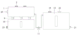
FIG. 1 is a front view of an environmental engineering sewage treatment plant according to the present invention.
FIG. 2 is a sectional view of a filter box of the sewage treatment device in environmental engineering.
FIG. 3 is a sectional view of a settling tank of the sewage treatment device in environmental engineering.
FIG. 4 is a top view of a cleaning brush of the sewage treatment apparatus of environmental engineering according to the present invention.
Reference numbers in the figures: 1. a filter box; 2. a first drive motor; 3. a screw rod; 4. a drive nut; 5. cleaning a brush; 6. a guide hole; 7. a guide bar; 8. a filter screen; 9. a blow-off pipe; 10. a collection box; 11. a water pump; 12. a settling tank; 13. a first stirring paddle; 14. a first pulley; 15. a second pulley; 16. a second stirring paddle; 17. a third stirring paddle; 18. a second drive motor; 19. a third belt pulley; 20. a fourth belt pulley; 21. a water outlet; 22. a feed hopper; 23. a sewage draining outlet; 24. a residue-proof plate; 25. a water inlet; 26. and (4) a water flowing hole.
Detailed Description
The preferred embodiments of the present invention will be described in conjunction with the accompanying drawings, and it will be understood that they are described herein for the purpose of illustration and explanation and not limitation.
The first embodiment is as follows:
as shown in fig. 1-4, an environmental engineering sewage treatment device comprises a filter box 1, wherein a first driving motor 2 is symmetrically and fixedly arranged on the top of the filter box 1, the bottom of the first driving motor 2 is fixedly connected with a screw rod 3 through a transmission shaft, the screw rod 3 is fixedly arranged in the inner cavity of the filter box 1 through a rotating shaft, the outer side of the screw rod 3 is connected with a cleaning brush 5 through a driving nut 4, the first driving motor 2 is arranged, the first driving motor 2 can drive the screw rod 3 to rotate clockwise or anticlockwise, the screw rod 3 can control the driving nut 4 to lift or lower through rotating clockwise or anticlockwise, the cleaning brush 5 can be controlled to lift, the cleaning brush 5 can clean the surface of a filter screen 8, the filter holes of the filter screen 8 can be prevented from being blocked, guide holes 6 are dug on the cleaning brush 5, guide rods 7 are inserted in the inner cavity of the guide holes 6, the guide rod 7 is vertically and fixedly arranged in the inner cavity of the filter box 1, the cleaning brush 5 can be guided and limited by arranging the guide rod 7, the cleaning brush 5 can be prevented from rotating and shaking, the filter screen 8 is fixedly arranged at one side of the cleaning brush 5 in the inner cavity of the filter box 1, the bottom of the filter box 1 is fixedly provided with a blow-off pipe 9 at equal intervals, the bottom of the blow-off pipe 9 is fixedly provided with a collecting box 10 in a penetrating way, the impurity garbage filtered by the filter screen 8 can be collected by arranging the collecting box 10, one side of the bottom of the filter box 1 is connected with a water pump 11 through a pipeline, the water pump 11 can convey the sewage in the inner cavity of the filter box 1 to the inner cavity of the sedimentation box 12, the water outlet end at one side of the water pump 11 is connected with the sedimentation box 12 through a pipeline, the inner cavity of the sedimentation box 12 is fixedly connected with a first stirring paddle 13 through a, the inner chamber of the settling tank 12 is located at two sides of the first stirring paddle 13 and is connected with a second stirring paddle 16 and a third stirring paddle 17 through a rotating shaft, a second driving motor 18 is fixedly arranged at the top of the settling tank 12, the bottom of the second driving motor 18 is fixedly connected with the second stirring paddle 16 through a transmission shaft, a third belt pulley 19 is fixedly arranged at the outer side of the top of the second stirring paddle 16, the third belt pulley 19 is connected with the first belt pulley 14 through a belt, a fourth belt pulley 20 is fixedly arranged at the outer side of the bottom of the third stirring paddle 17, the fourth belt pulley 20 is connected with the second belt pulley 15 through a belt, the second driving motor 18 can drive the second stirring paddle 16 to rotate, the second stirring paddle 16 can drive the first stirring paddle 13 to rotate through the third belt pulley 19, and the first stirring paddle 13 can drive the third stirring paddle 17 to rotate through the second belt pulley 15, the coagulant and the water can be fully stirred and mixed, and the adsorption and precipitation efficiency and effect of impurities in the water body can be improved.
In this embodiment, a water outlet 21 is disposed on one side of the bottom of the settling tank 12, a valve is disposed on the top of the water outlet 21, a feeding funnel 22 is fixedly disposed on one side of the second driving motor 18 on the top of the settling tank 12, and the feeding funnel 22 is disposed to facilitate adding coagulant into the inner cavity of the settling tank 12.
In this embodiment, collecting box 10 bottom one side is equipped with drain 23, just drain 23 tip is equipped with the lid stopper, conveniently clears up the rubbish of collecting box 10 inner chamber, the fixed board 24 that prevents remaining that is equipped with in collecting box 10 inner chamber bottom sets up and prevents remaining board 24 and can prevent that rubbish from remaining in collecting box 10 inner chamber, collecting box 10 and setting 12 front side surfaces all are equipped with the glass window, set up the volume of the rubbish that the glass window conveniently watched collecting box 10 inner chamber and the volume of the sewage of setting 12 inner chambers of setting up.
In this embodiment, a water inlet 25 is arranged on one side of the filtering tank 1, and the water inlet 25 is connected with a sewage pipe.
In this embodiment, the blow-off pipe 9 is set to be funnel-shaped, and a valve is arranged on one side of the blow-off pipe 9, so that garbage can flow into the inner cavity of the collection box 10 to be collected conveniently.
Example two:
as shown in fig. 3, water flow holes 26 are dug in the blades of the first stirring paddle 13, the second stirring paddle 16 and the third stirring paddle 17 at equal intervals, and the water flow holes 26 can reduce water flow resistance and improve stirring effect.
The working principle of the invention is as follows: the filter screen 8 can carry out layered filtration on impurities in sewage, the first driving motor 2 can drive the screw rod 3 to rotate clockwise or anticlockwise, the screw rod 3 can control the driving nut 4 to lift by rotating clockwise or anticlockwise so as to control the cleaning brush 5 to lift, the cleaning brush 5 can clean the surface of the filter screen 8 so as to prevent the filter holes of the filter screen 8 from being blocked, the guide rod 7 can guide and limit the cleaning brush 5 so as to prevent the cleaning brush 5 from rotating and shaking, the collecting box 10 can collect impurity garbage filtered by the filter screen 8, the second driving motor 18 can drive the second stirring paddle 16 to rotate, the second stirring paddle 16 can drive the first stirring paddle 13 to rotate through the third belt pulley 19, the first stirring paddle 13 can drive the third stirring paddle 17 to rotate through the second belt pulley 15, and the coagulant and water can be fully stirred and mixed, can improve the efficiency and the effect of adsorption and precipitation of impurities in the water body.
The above embodiments are preferred embodiments of the present invention, and those skilled in the art can make variations and modifications to the above embodiments, therefore, the present invention is not limited to the above embodiments, and any obvious improvements, substitutions or modifications made by those skilled in the art based on the present invention are within the protection scope of the present invention.
Claims (9)
1. The utility model provides an environmental engineering sewage treatment plant, includes rose box (1), its characterized in that: the filter box is characterized in that a first driving motor (2) is symmetrically and fixedly arranged at the top of the filter box (1), the bottom of the first driving motor (2) is fixedly connected with a lead screw (3) through a transmission shaft, the lead screw (3) is fixedly arranged in the inner cavity of the filter box (1) through a rotating shaft, the outer side of the lead screw (3) is connected with a cleaning brush (5) through a driving nut (4), a guide hole (6) is dug on the cleaning brush (5), a guide rod (7) is inserted in the inner cavity of the guide hole (6), the guide rod (7) is vertically and fixedly arranged in the inner cavity of the filter box (1), a filter screen (8) is fixedly arranged at one side of the cleaning brush (5) in the inner cavity of the filter box (1), drain pipes (9) are fixedly arranged at equal intervals at the bottom of the filter box (1), a collecting box (10) is fixedly arranged at the bottom of the drain pipes (9), and a, the water outlet end on one side of the water pump (11) is connected with a settling tank (12) through a pipeline, the inner cavity of the settling tank (12) is connected with a first stirring paddle (13) through a rotating shaft, the top and the bottom of the first stirring paddle (13) are respectively and fixedly sleeved with a first belt pulley (14) and a second belt pulley (15), the inner cavity of the settling tank (12) is positioned on two sides of the first stirring paddle (13) and is connected with a second stirring paddle (16) and a third stirring paddle (17) through a rotating shaft, the top of the settling tank (12) is fixedly provided with a second driving motor (18), the bottom of the second driving motor (18) is fixedly connected with the second stirring paddle (16) through a transmission shaft, the outer side of the top of the second stirring paddle (16) is fixedly sleeved with a third belt pulley (19), the third belt pulley (19) is connected with the first belt pulley (14) through a belt, the outer side of the bottom of the third stirring paddle (17) is fixedly sleeved, and the fourth belt pulley (20) is connected with the second belt pulley (15) through a belt.
2. The environmental engineering sewage treatment plant of claim 1, wherein: a water outlet (21) is arranged on one side of the bottom of the settling tank (12), and a valve is arranged at the top of the water outlet (21).
3. The environmental engineering sewage treatment plant of claim 1, wherein: the top of the settling tank (12) is positioned at one side of the second driving motor (18) and fixedly provided with a feeding funnel (22) in a penetrating way.
4. The environmental engineering sewage treatment plant of claim 1, wherein: one side of the bottom of the collecting box (10) is provided with a drain outlet (23), and the end part of the drain outlet (23) is provided with a cover plug.
5. The environmental engineering sewage treatment plant of claim 1, wherein: and a residue-preventing plate (24) is fixedly arranged at the bottom of the inner cavity of the collecting box (10).
6. The environmental engineering sewage treatment plant of claim 1, wherein: one side of the filter box (1) is provided with a water inlet (25), and the water inlet (25) is connected with a sewage pipe.
7. The environmental engineering sewage treatment plant of claim 1, wherein: the front side surfaces of the collecting box (10) and the settling box (12) are respectively provided with a glass window.
8. The environmental engineering sewage treatment plant of claim 1, wherein: the drainage pipe (9) is in a funnel shape, and a valve is arranged on one side of the drainage pipe (9).
9. The environmental engineering sewage treatment plant of claim 1, wherein: and the blades of the first stirring paddle (13), the second stirring paddle (16) and the third stirring paddle (17) are provided with water flowing holes (26) dug at equal intervals.
Priority Applications (1)
| Application Number | Priority Date | Filing Date | Title |
|---|---|---|---|
| CN202011528940.XA CN112499834A (en) | 2020-12-22 | 2020-12-22 | Environmental engineering sewage treatment plant |
Applications Claiming Priority (1)
| Application Number | Priority Date | Filing Date | Title |
|---|---|---|---|
| CN202011528940.XA CN112499834A (en) | 2020-12-22 | 2020-12-22 | Environmental engineering sewage treatment plant |
Publications (1)
| Publication Number | Publication Date |
|---|---|
| CN112499834A true CN112499834A (en) | 2021-03-16 |
Family
ID=74923327
Family Applications (1)
| Application Number | Title | Priority Date | Filing Date |
|---|---|---|---|
| CN202011528940.XA Withdrawn CN112499834A (en) | 2020-12-22 | 2020-12-22 | Environmental engineering sewage treatment plant |
Country Status (1)
| Country | Link |
|---|---|
| CN (1) | CN112499834A (en) |
Cited By (1)
| Publication number | Priority date | Publication date | Assignee | Title |
|---|---|---|---|---|
| JP7315268B1 (en) | 2022-06-14 | 2023-07-26 | 株式会社ペイントサービス | Wastewater treatment system with flocculation tank to which flocculant is added |
Citations (4)
| Publication number | Priority date | Publication date | Assignee | Title |
|---|---|---|---|---|
| JP2007050384A (en) * | 2005-08-19 | 2007-03-01 | Kato Tekko Kk | Solid-liquid separator |
| CN210409692U (en) * | 2019-08-13 | 2020-04-28 | 李国伟 | Sewage treatment plant for environmental engineering |
| CN210505715U (en) * | 2019-08-21 | 2020-05-12 | 内蒙古三联金山化工有限责任公司 | Waste hydrochloric acid treatment device |
| CN210683417U (en) * | 2019-07-23 | 2020-06-05 | 赖许新 | Waste liquid treatment device for clothing factory |
-
2020
- 2020-12-22 CN CN202011528940.XA patent/CN112499834A/en not_active Withdrawn
Patent Citations (4)
| Publication number | Priority date | Publication date | Assignee | Title |
|---|---|---|---|---|
| JP2007050384A (en) * | 2005-08-19 | 2007-03-01 | Kato Tekko Kk | Solid-liquid separator |
| CN210683417U (en) * | 2019-07-23 | 2020-06-05 | 赖许新 | Waste liquid treatment device for clothing factory |
| CN210409692U (en) * | 2019-08-13 | 2020-04-28 | 李国伟 | Sewage treatment plant for environmental engineering |
| CN210505715U (en) * | 2019-08-21 | 2020-05-12 | 内蒙古三联金山化工有限责任公司 | Waste hydrochloric acid treatment device |
Cited By (2)
| Publication number | Priority date | Publication date | Assignee | Title |
|---|---|---|---|---|
| JP7315268B1 (en) | 2022-06-14 | 2023-07-26 | 株式会社ペイントサービス | Wastewater treatment system with flocculation tank to which flocculant is added |
| JP2023182508A (en) * | 2022-06-14 | 2023-12-26 | 株式会社ペイントサービス | Waste water treatment system with flocculation tank to which flocculant is added |
Similar Documents
| Publication | Publication Date | Title |
|---|---|---|
| CN208362125U (en) | A kind of packaged type garbage leachate treatment device | |
| CN108751528A (en) | A kind of high-efficiency industrial wastewater processing unit | |
| CN211620304U (en) | Microbial purification sewage treatment device | |
| CN112499834A (en) | Environmental engineering sewage treatment plant | |
| CN110759518A (en) | Urban sewage comprehensive treatment device | |
| CN215439944U (en) | Multi-pipeline discharging device for medical sewage treatment | |
| CN212356916U (en) | Integral type sewage treatment device | |
| CN211419924U (en) | High-efficient sewage treatment device | |
| CN209392846U (en) | A kind of filter of easy cleaning | |
| CN208454682U (en) | A kind of environment-friendly sewage processing unit | |
| CN212403739U (en) | Sewage treatment device convenient to clearance filter screen board | |
| CN211864050U (en) | Filter equipment is used in dephosphorization flocculating agent production | |
| CN210764796U (en) | Domestic waste penetrant purifier | |
| CN209974390U (en) | Sewage flocculation sedimentation mechanism | |
| CN211035474U (en) | Chemical wastewater recycling, filtering and purifying device | |
| CN210683417U (en) | Waste liquid treatment device for clothing factory | |
| CN208964675U (en) | A kind of wheel hub cover productive power electroplating wastewater treatment device | |
| CN220723890U (en) | Coagulation device for water pollution chemical treatment | |
| CN214861478U (en) | Advanced treatment device for oil extraction sewage in oil field | |
| CN213569988U (en) | Sewage treatment tank | |
| CN218371835U (en) | High-efficient air supporting coagulating sedimentation equipment | |
| CN218910088U (en) | Village and town domestic wastewater edulcoration device | |
| CN221601401U (en) | Chemical wastewater treatment device | |
| CN207913341U (en) | A kind of water purification apparatus | |
| CN221084793U (en) | Storage device of waste water |
Legal Events
| Date | Code | Title | Description |
|---|---|---|---|
| PB01 | Publication | ||
| PB01 | Publication | ||
| SE01 | Entry into force of request for substantive examination | ||
| SE01 | Entry into force of request for substantive examination | ||
| WW01 | Invention patent application withdrawn after publication | ||
| WW01 | Invention patent application withdrawn after publication |
Application publication date: 20210316 |