CN112476365A - Workstation of worm wheel supercharger casing processing - Google Patents
Workstation of worm wheel supercharger casing processing Download PDFInfo
- Publication number
- CN112476365A CN112476365A CN202011365450.2A CN202011365450A CN112476365A CN 112476365 A CN112476365 A CN 112476365A CN 202011365450 A CN202011365450 A CN 202011365450A CN 112476365 A CN112476365 A CN 112476365A
- Authority
- CN
- China
- Prior art keywords
- turbocharger
- machining
- workbench
- arc
- driving box
- Prior art date
- Legal status (The legal status is an assumption and is not a legal conclusion. Google has not performed a legal analysis and makes no representation as to the accuracy of the status listed.)
- Pending
Links
- 230000005540 biological transmission Effects 0.000 claims abstract description 33
- 238000003754 machining Methods 0.000 claims abstract description 19
- 230000002457 bidirectional effect Effects 0.000 claims description 19
- 230000033001 locomotion Effects 0.000 claims description 9
- 230000000712 assembly Effects 0.000 claims description 8
- 238000000429 assembly Methods 0.000 claims description 8
- 238000003860 storage Methods 0.000 claims description 7
- 230000001788 irregular Effects 0.000 abstract description 4
- 238000000034 method Methods 0.000 description 7
- 238000010586 diagram Methods 0.000 description 2
- 238000004519 manufacturing process Methods 0.000 description 2
- 230000009286 beneficial effect Effects 0.000 description 1
- 238000005516 engineering process Methods 0.000 description 1
Images


Classifications
-
- B—PERFORMING OPERATIONS; TRANSPORTING
- B25—HAND TOOLS; PORTABLE POWER-DRIVEN TOOLS; MANIPULATORS
- B25H—WORKSHOP EQUIPMENT, e.g. FOR MARKING-OUT WORK; STORAGE MEANS FOR WORKSHOPS
- B25H1/00—Work benches; Portable stands or supports for positioning portable tools or work to be operated on thereby
- B25H1/02—Work benches; Portable stands or supports for positioning portable tools or work to be operated on thereby of table type
- B25H1/04—Work benches; Portable stands or supports for positioning portable tools or work to be operated on thereby of table type portable
-
- B—PERFORMING OPERATIONS; TRANSPORTING
- B25—HAND TOOLS; PORTABLE POWER-DRIVEN TOOLS; MANIPULATORS
- B25H—WORKSHOP EQUIPMENT, e.g. FOR MARKING-OUT WORK; STORAGE MEANS FOR WORKSHOPS
- B25H1/00—Work benches; Portable stands or supports for positioning portable tools or work to be operated on thereby
- B25H1/10—Work benches; Portable stands or supports for positioning portable tools or work to be operated on thereby with provision for adjusting holders for tool or work
-
- F—MECHANICAL ENGINEERING; LIGHTING; HEATING; WEAPONS; BLASTING
- F21—LIGHTING
- F21V—FUNCTIONAL FEATURES OR DETAILS OF LIGHTING DEVICES OR SYSTEMS THEREOF; STRUCTURAL COMBINATIONS OF LIGHTING DEVICES WITH OTHER ARTICLES, NOT OTHERWISE PROVIDED FOR
- F21V33/00—Structural combinations of lighting devices with other articles, not otherwise provided for
Abstract
The invention relates to a workbench for machining a turbocharger shell, which comprises a bearing table and a driving box arranged on the bearing table, wherein a plurality of supporting legs are arranged at the side end of the driving box; the clamping assembly comprises a mounting seat connected with the threaded transmission assembly and a fixing piece fixed on the mounting seat, a movable plate in sliding fit with the mounting seat is inserted into the inner side of the fixing piece, a clamping plate is rotatably installed on the movable plate through a connecting shaft, and the connecting shaft is further connected with a movable driving assembly installed on the fixing piece. The irregular turbocharger housing is prevented from contacting the console during rotation.
Description
Technical Field
The invention relates to the technical field related to machining of a turbocharger, in particular to a workbench for machining a turbocharger shell.
Background
Modern enterprises basically adopt assembly line operation to improve production efficiency, one assembly line is generally provided with dozens or dozens of work stations, each work station is provided with a fixed assembly line workbench, and one or more operators are configured on each assembly line workbench to receive each or more assembly rings in the product manufacturing process.
In the turbo charger casing processing procedure, because the turbo charger casing belongs to irregular shape, in the centre gripping process, be to other position processing when needs, need rotate the turbo charger casing, but current workstation in the use, can't realize fixture and rotate, and partly rotatable fixture produces the interference with the workstation easily when the turbo charger casing rotates, influences the processing procedure.
Disclosure of Invention
The invention aims to provide a workbench for machining a turbocharger shell, which aims to solve the problems in the background technology.
In order to achieve the purpose, the invention provides the following technical scheme:
a workbench for machining a turbocharger shell comprises a bearing table and a driving box arranged on the bearing table, wherein a plurality of supporting legs are arranged at the side end of the driving box, an operating table is arranged on one side, far away from the driving box, of the bearing table, two clamping assemblies are symmetrically arranged on the operating table and connected with a threaded transmission assembly arranged in the operating table, the threaded transmission assembly is connected with a driving mechanism arranged in the driving box, and the driving mechanism drives the two clamping assemblies to move oppositely or oppositely through the threaded transmission assembly;
the centre gripping subassembly include with the mount pad that the screw thread drive assembly is connected and fix mounting on the mount pad, the inboard of mounting is inserted and is put its sliding fit's fly leaf, rotate through the connecting axle on the fly leaf and install the grip block, the connecting axle still with install movable drive assembly on the mounting is connected, works as during the motion of movable drive assembly, in order to drive grip block vertical movement, and self takes place to rotate.
As a further scheme of the invention: the bearing platform is further provided with an arc-shaped guide rod, the arc-shaped guide rod is connected with a sliding sleeve through a sliding limiting assembly, one side of the bearing platform, which is far away from the sliding sleeve, is fixed with a support, and the support is rotatably provided with a lighting lamp.
As a still further scheme of the invention: the sliding limiting assembly comprises an arc limiting protrusion fixed on the arc guide rod and an arc limiting sliding groove arranged on the inner wall of the sliding sleeve and in sliding fit with the arc limiting protrusion.
As a still further scheme of the invention: the movable driving assembly comprises an electric telescopic rod installed on the fixing piece, the movable end of the electric telescopic rod is fixedly connected with the movable plate, the movable end of the electric telescopic rod is further fixed to a rack plate on the fixing piece, and the rack plate is meshed with a gear on the connecting shaft.
As a still further scheme of the invention: and a rubber bulge is arranged on one side of the clamping plate, which is far away from the connecting shaft.
As a still further scheme of the invention: the thread transmission assembly comprises a bidirectional threaded rod rotatably mounted on the inner side of the operating platform and two thread sleeves which are in threaded connection with the bidirectional threaded rod and are symmetrical about a middle vertical line of the bidirectional threaded rod, and the thread sleeves are fixedly connected with the mounting seat;
one end of the bidirectional threaded rod is connected with the driving mechanism through a transmission belt.
As a still further scheme of the invention: the driving mechanism comprises a motor arranged in the driving box, a worm is fixed on an output shaft of the motor and meshed with a worm wheel rotatably arranged on the inner wall of the driving box, a rotating shaft of the worm wheel is rotatably connected with a transmission shaft through a bevel gear set, and the transmission shaft is rotatably connected with the bidirectional threaded rod through a transmission belt.
As a still further scheme of the invention: the inner side of the driving box is also provided with a storage battery, and the storage battery is electrically connected with the motor and the electric telescopic rod.
Compared with the prior art, the invention has the beneficial effects that: the clamping plate and the clamped turbocharger shell are driven to rotate by the arranged movable driving assembly, and the clamping plate and the clamped turbocharger shell can rotate simultaneously, so that the irregular turbocharger shell is prevented from contacting with an operation table in the rotating process to influence the rotation, and the practicability is high.
Drawings
Fig. 1 is a schematic structural diagram of a workbench for machining a turbocharger housing.
Fig. 2 is a cross-sectional view of a table for machining a turbocharger housing.
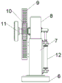
Fig. 3 is a schematic structural view of a front view of a clamping mechanism in a workbench for machining a turbocharger housing.
Fig. 4 is a structural schematic diagram of a rear view of a clamping mechanism in a workbench for machining a turbocharger housing.
Fig. 5 is a schematic view of the connection between the fixed member and the movable plate in the working table for machining the housing of the turbocharger.
In the figure: 1-a bearing table, 2-supporting legs, 3-a driving box, 4-an arc-shaped guide rod, 5-an operation table, 6-a mounting seat, 7-a fixing part, 8-a movable plate, 9-a rack plate, 10-a gear, 11-a clamping plate, 12-an electric telescopic rod, 13-a lighting lamp, 14-a bracket, 15-a sliding sleeve, 16-a bidirectional threaded rod, 17-a threaded sleeve, 18-a transmission shaft, 19-a bevel gear set, 20-a worm wheel, 21-a worm, 22-a motor and 23-a storage battery.
Detailed Description
The technical solutions in the embodiments of the present invention will be clearly and completely described below with reference to the drawings in the embodiments of the present invention, and it is obvious that the described embodiments are only a part of the embodiments of the present invention, and not all of the embodiments. All other embodiments, which can be derived by a person skilled in the art from the embodiments given herein without making any creative effort, shall fall within the protection scope of the present invention.
In addition, an element of the present invention may be said to be "fixed" or "disposed" to another element, either directly on the other element or with intervening elements present. When an element is referred to as being "connected" to another element, it can be directly connected to the other element or intervening elements may also be present. The terms "vertical," "horizontal," "left," "right," and the like as used herein are for illustrative purposes only and do not represent the only embodiments.
Referring to fig. 1 to 5, in the embodiment of the invention, the workbench for machining the housing of the turbocharger comprises a bearing table 1 and a driving box 3 installed on the bearing table 1, a plurality of supporting legs 2 are installed at the side end of the driving box 3, an operation table 5 is installed at one side, away from the driving box 3, of the bearing table 1, two clamping assemblies are symmetrically installed on the operation table 5, the two clamping assemblies are connected with a thread transmission assembly installed in the operation table 5, the thread transmission assembly is connected with a driving mechanism installed in the driving box 3, and the driving mechanism drives the two clamping assemblies to move oppositely or oppositely through the thread transmission assembly;
the centre gripping subassembly include with mount pad 6 that screw thread drive assembly connects and fix mounting 7 on the mount pad 6, sliding fit's fly leaf 8 with it has been inserted to the inboard of mounting 7, install grip block 11 through the connecting axle rotation on the fly leaf 8, the connecting axle still with install movable drive assembly on the mounting 7 is connected, works as during the motion of movable drive assembly, in order to drive 11 vertical motion of grip block, and self take place to rotate.
In the embodiment of the invention, the thread transmission assembly is driven to move by the arranged driving mechanism, when the thread transmission assembly moves, the two clamping assemblies are driven to move oppositely or oppositely, so that the turbocharger shell is clamped or loosened, when the turbocharger shell needs to be processed at each position, the clamping plate 11 and the clamped turbocharger shell are driven to rotate by the arranged movable driving assembly, and meanwhile, the clamping plate 11 and the turbocharger shell can rotate, so that the irregular turbocharger shell is prevented from contacting with the operating table 5 in the rotating process to influence the rotation, and the practicability is strong.
In the embodiment of the present invention, it should be noted that the fixing element 7 is provided with an embedded groove for the movable plate 8 to slide, and one side of the embedded groove facing the clamping plate 11 is provided with an opening shape, so as to increase the vertical movable range of the clamping plate 11.
In the embodiment of the invention, the supporting legs 2 can be provided with rollers according to requirements so as to facilitate the movement of the workbench, and the rollers are provided with braking pieces so as to ensure the stability of the workbench in the using process.
As another embodiment of the present invention, an arc-shaped guide rod 4 is further installed on the receiving platform 1, a sliding sleeve 15 is connected to the arc-shaped guide rod 4 through a sliding limiting assembly, a support 14 is fixed on one side of the sliding sleeve 15, which is far away from the receiving platform 1, and an illuminating lamp 13 is rotatably installed on the support 14.
In the embodiment of the invention, the position of the support 14 and the lighting lamp 13 can be integrally adjusted by the aid of the arc-shaped guide rod 4 and the sliding sleeve 15, so that different lighting requirements can be met, and the lighting lamp 13 can rotate on the support 14, so that the lighting position is further enlarged, and the practicability is high.
As another embodiment of the present invention, the sliding limiting component includes an arc-shaped limiting protrusion fixed on the arc-shaped guiding rod 4 and an arc-shaped limiting sliding groove disposed on the inner wall of the sliding sleeve 15 and slidably engaged with the arc-shaped limiting protrusion.
In the embodiment of the present invention, the sliding sleeve 15 can move on the arc-shaped guide rod 4 by the arc-shaped limiting protrusion matching with the arc-shaped limiting sliding groove, but cannot rotate on the arc-shaped guide rod 4, so as to ensure that the bracket 14 keeps a vertical state.
As another embodiment of the present invention, the movable driving assembly includes an electric telescopic rod 12 mounted on the fixed member 7, a movable end of the electric telescopic rod 12 is fixedly connected to the movable plate 8, and a rack plate 9 fixed on the fixed member 7, wherein the rack plate 9 is engaged with a gear 10 mounted on the connecting shaft.
In the embodiment of the invention, the movable plate 8 is driven to vertically move relative to the fixing part 7 through the telescopic motion of the arranged electric telescopic rod 12, the clamping plate 11 is driven to move when the movable plate 8 moves, and the gear 10 rotates under the action of the rack plate 9 to drive the connecting shaft and the clamping plate 11 fixed with the connecting shaft to rotate, so that the clamped turbocharger shell rotates and performs lifting operation.
As another embodiment of the present invention, a rubber protrusion is installed on a side of the clamping plate 11 away from the connecting shaft.
In the embodiment of the invention, the friction force between the clamping plate 11 and the turbocharger shell can be effectively increased through the arranged rubber bulge, the stability in the clamping process is ensured, meanwhile, the arranged rubber bulge can also play a certain protection role on the turbocharger shell, and the phenomenon that the turbocharger shell is abraded due to rigid contact between the clamping plate 11 and the turbocharger shell is effectively prevented.
As another embodiment of the present invention, the screw transmission assembly includes a bidirectional threaded rod 16 rotatably mounted inside the operating table 5, and two screw sleeves 17 screwed on the bidirectional threaded rod 16 and symmetrical about a perpendicular line in the bidirectional threaded rod 16, wherein the screw sleeves 17 are fixedly connected to the mounting seat 6;
one end of the bidirectional threaded rod 16 is connected with the driving mechanism through a transmission belt.
In the embodiment of the invention, when the bidirectional threaded rod 16 is rotated by the driving mechanism, the two threaded sleeves 17 are matched to drive the two mounting seats 6 to move towards each other or move oppositely, so that the clamping state is changed.
In the embodiment of the invention, it can be understood that a cavity is arranged on the inner side of the operating platform 5, the bidirectional threaded rod 16 is rotatably installed in the cavity, a through groove is arranged on one side of the cavity facing the mounting seat 6, a connecting block for connecting the mounting seat 6 and the threaded sleeve 17 is slidably installed in the through groove, and the through groove can limit the movement of the connecting block.
As another embodiment of the present invention, the driving mechanism includes a motor 22 installed in the driving box 3, a worm 21 is fixed on an output shaft of the motor 22, the worm 21 is engaged with a worm wheel 20 rotatably installed on an inner wall of the driving box 3, a rotating shaft of the worm wheel 20 is rotatably connected with a transmission shaft 18 through a bevel gear set 19, and the transmission shaft 18 is rotatably connected with the bidirectional threaded rod 16 through a transmission belt.
In the embodiment of the invention, the worm 21 is driven to rotate by the arranged motor 22 so as to drive the worm wheel 20 to rotate, when the worm wheel 20 rotates, the transmission shaft 18 is driven to rotate by the action of the bevel gear set 19, and the transmission shaft 18 drives the bidirectional threaded rod 16 to rotate by the transmission belt, so that the driving requirement is realized.
In the embodiment of the present invention, the motor 22 is a forward and reverse rotation motor, and a 4IK/80 yyyjt motor is adopted, which has stable performance, and other types of motors can be adopted as long as the driving requirement is met, which is not specifically limited in this application.
In the embodiment of the present invention, the bevel gear set 19 is composed of two bevel gears perpendicular to each other and engaged with each other to perform a force steering transmission function, but the transmission ratio of the bevel gear set 19 is not particularly limited in this application and may be selected according to the requirement.
In another embodiment of the present invention, a battery 23 is further disposed inside the driving box 3, and the battery 23 is electrically connected to the motor 22 and the electric telescopic rod 12.
In the embodiment of the present invention, the storage battery 23 is provided to supply power to the motor 22 and the electric telescopic rod 12, but the storage battery 23 may be replaced by commercial power to supply power to the motor 22 and the electric telescopic rod 12, and the present application is not limited in particular.
It will be evident to those skilled in the art that the invention is not limited to the details of the foregoing illustrative embodiments, and that the present invention may be embodied in other specific forms without departing from the spirit or essential attributes thereof. The present embodiments are therefore to be considered in all respects as illustrative and not restrictive, the scope of the invention being indicated by the appended claims rather than by the foregoing description, and all changes which come within the meaning and range of equivalency of the claims are therefore intended to be embraced therein. Any reference sign in a claim should not be construed as limiting the claim concerned.
Furthermore, it should be understood that although the present description refers to embodiments, not every embodiment may contain only a single embodiment, and such description is for clarity only, and those skilled in the art should integrate the description, and the embodiments may be combined as appropriate to form other embodiments understood by those skilled in the art.
Claims (8)
1. The workbench for machining the turbocharger shell is characterized by comprising a bearing platform (1) and a driving box (3) installed on the bearing platform (1), a plurality of supporting legs (2) are installed at the side end of the driving box (3), an operating platform (5) is installed on one side, away from the driving box (3), of the bearing platform (1), two clamping assemblies are symmetrically installed on the operating platform (5) and connected with a thread transmission assembly installed in the operating platform (5), the thread transmission assembly is connected with a driving mechanism installed in the driving box (3), and the driving mechanism drives the two clamping assemblies to move oppositely or oppositely through the thread transmission assembly;
the centre gripping subassembly include with mount pad (6) that the screw thread drive assembly is connected and fix mounting (7) on mount pad (6), sliding fit's fly leaf (8) with it has been inserted to the inboard of mounting (7), install grip block (11) through the connecting axle rotation on fly leaf (8), the connecting axle still with install movable drive assembly on mounting (7) is connected, works as during the motion of movable drive assembly, in order to drive grip block (11) vertical motion, and self takes place to rotate.
2. The workbench for machining the housing of the turbocharger according to claim 1, wherein the receiving platform (1) is further provided with an arc-shaped guide rod (4), the arc-shaped guide rod (4) is connected with a sliding sleeve (15) through a sliding limiting assembly, a support (14) is fixed on one side of the sliding sleeve (15) far away from the receiving platform (1), and the support (14) is rotatably provided with a lighting lamp (13).
3. The workbench for machining the housing of the turbocharger as recited in claim 2, wherein the sliding limiting assembly comprises an arc-shaped limiting protrusion fixed on the arc-shaped guide rod (4) and an arc-shaped limiting sliding groove arranged on the inner wall of the sliding sleeve (15) and in sliding fit with the arc-shaped limiting protrusion.
4. The workbench for machining the housing of the turbocharger as recited in claim 1, wherein the movable driving assembly comprises an electric telescopic rod (12) mounted on the fixing member (7), the movable end of the electric telescopic rod (12) is fixedly connected with the movable plate (8), and further comprises a rack plate (9) fixed on the fixing member (7), wherein the rack plate (9) is meshed with a gear (10) mounted on the connecting shaft.
5. The workbench for machining the turbocharger shell as recited in claim 1, wherein a rubber bulge is arranged on one side of the clamping plate (11) far away from the connecting shaft.
6. The working table for machining the turbocharger shell according to claim 4, wherein the thread transmission assembly comprises a bidirectional threaded rod (16) rotatably mounted on the inner side of the operating table (5) and two thread sleeves (17) which are connected to the bidirectional threaded rod (16) in a threaded manner and are symmetrical about a perpendicular line in the bidirectional threaded rod (16), and the thread sleeves (17) are fixedly connected with the mounting seat (6);
one end of the bidirectional threaded rod (16) is connected with the driving mechanism through a transmission belt.
7. The workbench for machining the shell of the turbocharger as recited in claim 6, wherein the driving mechanism comprises a motor (22) installed in the driving box (3), a worm (21) is fixed on an output shaft of the motor (22), the worm (21) is meshed with a worm wheel (20) rotatably installed on the inner wall of the driving box (3), a rotating shaft of the worm wheel (20) is rotatably connected with a transmission shaft (18) through a bevel gear set (19), and the transmission shaft (18) is rotatably connected with the bidirectional threaded rod (16) through a transmission belt.
8. The workbench for machining the housing of the turbocharger as recited in claim 7, wherein a storage battery (23) is further arranged on the inner side of the driving box (3), and the storage battery (23) is electrically connected with the motor (22) and the electric telescopic rod (12).
Priority Applications (1)
| Application Number | Priority Date | Filing Date | Title |
|---|---|---|---|
| CN202011365450.2A CN112476365A (en) | 2020-11-28 | 2020-11-28 | Workstation of worm wheel supercharger casing processing |
Applications Claiming Priority (1)
| Application Number | Priority Date | Filing Date | Title |
|---|---|---|---|
| CN202011365450.2A CN112476365A (en) | 2020-11-28 | 2020-11-28 | Workstation of worm wheel supercharger casing processing |
Publications (1)
| Publication Number | Publication Date |
|---|---|
| CN112476365A true CN112476365A (en) | 2021-03-12 |
Family
ID=74936909
Family Applications (1)
| Application Number | Title | Priority Date | Filing Date |
|---|---|---|---|
| CN202011365450.2A Pending CN112476365A (en) | 2020-11-28 | 2020-11-28 | Workstation of worm wheel supercharger casing processing |
Country Status (1)
| Country | Link |
|---|---|
| CN (1) | CN112476365A (en) |
Cited By (2)
| Publication number | Priority date | Publication date | Assignee | Title |
|---|---|---|---|---|
| CN113399874A (en) * | 2021-06-04 | 2021-09-17 | 苏州诺克斯通讯科技有限公司 | High efficiency welding auxiliary fixtures |
| CN115106956A (en) * | 2022-07-19 | 2022-09-27 | 航天智讯新能源(山东)有限公司 | Fixing equipment for semiconductor device production |
Citations (10)
| Publication number | Priority date | Publication date | Assignee | Title |
|---|---|---|---|---|
| CN104972444A (en) * | 2014-04-10 | 2015-10-14 | 哈尔滨飞机工业集团有限责任公司 | Mechanism for tool lifting and rotating |
| CN109040358A (en) * | 2018-07-27 | 2018-12-18 | 维沃移动通信有限公司 | A kind of mobile terminal |
| JP2019188584A (en) * | 2018-04-28 | 2019-10-31 | 福建省通通発科技発展有限公司 | New type jig component for work-piece clamping |
| DE212020000027U1 (en) * | 2020-03-22 | 2020-04-23 | Suzhou Shengte Intelligent Technology Co., Ltd | A clamping and fastening device for the performance test of flexible materials |
| CN210909059U (en) * | 2019-10-25 | 2020-07-03 | 上海瑞超机械刀具制造有限公司 | Clamping device for machining |
| CN210967601U (en) * | 2019-07-24 | 2020-07-10 | 南通灵顿机械有限公司 | Welding tool clamp for middle shell of turbocharger |
| CN111482861A (en) * | 2020-04-20 | 2020-08-04 | 重庆鼎鼎科技有限公司 | Automatic chamfering machine for processing automobile parts |
| CN111673500A (en) * | 2020-06-10 | 2020-09-18 | 张雪蓉 | Clamping device |
| CN211966716U (en) * | 2020-04-15 | 2020-11-20 | 叶小武 | Machining clamp |
| CN212020069U (en) * | 2020-04-29 | 2020-11-27 | 翔鹰航空工业有限公司 | Positioning device is used in aeroengine accessory processing convenient to adjust |
-
2020
- 2020-11-28 CN CN202011365450.2A patent/CN112476365A/en active Pending
Patent Citations (10)
| Publication number | Priority date | Publication date | Assignee | Title |
|---|---|---|---|---|
| CN104972444A (en) * | 2014-04-10 | 2015-10-14 | 哈尔滨飞机工业集团有限责任公司 | Mechanism for tool lifting and rotating |
| JP2019188584A (en) * | 2018-04-28 | 2019-10-31 | 福建省通通発科技発展有限公司 | New type jig component for work-piece clamping |
| CN109040358A (en) * | 2018-07-27 | 2018-12-18 | 维沃移动通信有限公司 | A kind of mobile terminal |
| CN210967601U (en) * | 2019-07-24 | 2020-07-10 | 南通灵顿机械有限公司 | Welding tool clamp for middle shell of turbocharger |
| CN210909059U (en) * | 2019-10-25 | 2020-07-03 | 上海瑞超机械刀具制造有限公司 | Clamping device for machining |
| DE212020000027U1 (en) * | 2020-03-22 | 2020-04-23 | Suzhou Shengte Intelligent Technology Co., Ltd | A clamping and fastening device for the performance test of flexible materials |
| CN211966716U (en) * | 2020-04-15 | 2020-11-20 | 叶小武 | Machining clamp |
| CN111482861A (en) * | 2020-04-20 | 2020-08-04 | 重庆鼎鼎科技有限公司 | Automatic chamfering machine for processing automobile parts |
| CN212020069U (en) * | 2020-04-29 | 2020-11-27 | 翔鹰航空工业有限公司 | Positioning device is used in aeroengine accessory processing convenient to adjust |
| CN111673500A (en) * | 2020-06-10 | 2020-09-18 | 张雪蓉 | Clamping device |
Cited By (3)
| Publication number | Priority date | Publication date | Assignee | Title |
|---|---|---|---|---|
| CN113399874A (en) * | 2021-06-04 | 2021-09-17 | 苏州诺克斯通讯科技有限公司 | High efficiency welding auxiliary fixtures |
| CN113399874B (en) * | 2021-06-04 | 2023-06-27 | 苏州诺克斯通讯科技有限公司 | High-efficiency welding auxiliary tool |
| CN115106956A (en) * | 2022-07-19 | 2022-09-27 | 航天智讯新能源(山东)有限公司 | Fixing equipment for semiconductor device production |
Similar Documents
| Publication | Publication Date | Title |
|---|---|---|
| CN112476365A (en) | Workstation of worm wheel supercharger casing processing | |
| CN112873089A (en) | Clamping device for bearing machining | |
| CN211401632U (en) | Automobile power generation machine shell adds clamping apparatus | |
| CN109879205A (en) | A kind of urban architecture glass attachment device | |
| CN216442167U (en) | Universal joint wheel hub bearing production and processing equipment | |
| CN110562210A (en) | Rotary air knife | |
| CN206961694U (en) | A kind of energy storage device for automatic change-over | |
| CN208663149U (en) | A kind of lathe bench vice | |
| CN108032658B (en) | A kind of double end skill work engraving machine | |
| CN209021261U (en) | A kind of pipe cutting machine for saving tailing | |
| CN112893894A (en) | Lathe for slotting bearing inner ring | |
| CN215364255U (en) | Gas shield welding wire rolling equipment | |
| CN219649524U (en) | Omnibearing polishing device for processing rear axle of electric vehicle | |
| CN211371240U (en) | Worm gear case | |
| CN108225280A (en) | Modular light source support for machine vision | |
| CN213795232U (en) | Limiting device for machine tool | |
| CN220838815U (en) | Motor armature shaft press-fitting device | |
| CN216888869U (en) | Mutual feed mechanism of linkage rotation that revolution adds rotation | |
| CN208155312U (en) | Modular light source support for machine vision | |
| CN214557748U (en) | Cutting device is used in motor accessories production | |
| CN213380342U (en) | Differential mechanism positioning tool | |
| CN219911530U (en) | Bearing pedestal for precision bearing | |
| CN218335578U (en) | Multipurpose motor structure | |
| CN216503952U (en) | Electromechanical integrated numerical control machining equipment with high machining efficiency | |
| CN216030922U (en) | Innovative single-shaft robot package |
Legal Events
| Date | Code | Title | Description |
|---|---|---|---|
| PB01 | Publication | ||
| PB01 | Publication | ||
| SE01 | Entry into force of request for substantive examination | ||
| SE01 | Entry into force of request for substantive examination | ||
| RJ01 | Rejection of invention patent application after publication | ||
| RJ01 | Rejection of invention patent application after publication |
Application publication date: 20210312 |