CN112469940A - Optical device for a motor vehicle headlight with a light guide - Google Patents
Optical device for a motor vehicle headlight with a light guide Download PDFInfo
- Publication number
- CN112469940A CN112469940A CN201980051448.7A CN201980051448A CN112469940A CN 112469940 A CN112469940 A CN 112469940A CN 201980051448 A CN201980051448 A CN 201980051448A CN 112469940 A CN112469940 A CN 112469940A
- Authority
- CN
- China
- Prior art keywords
- light
- holder
- region
- cover element
- projection
- Prior art date
- Legal status (The legal status is an assumption and is not a legal conclusion. Google has not performed a legal analysis and makes no representation as to the accuracy of the status listed.)
- Pending
Links
Images


Classifications
-
- F—MECHANICAL ENGINEERING; LIGHTING; HEATING; WEAPONS; BLASTING
- F21—LIGHTING
- F21S—NON-PORTABLE LIGHTING DEVICES; SYSTEMS THEREOF; VEHICLE LIGHTING DEVICES SPECIALLY ADAPTED FOR VEHICLE EXTERIORS
- F21S41/00—Illuminating devices specially adapted for vehicle exteriors, e.g. headlamps
- F21S41/20—Illuminating devices specially adapted for vehicle exteriors, e.g. headlamps characterised by refractors, transparent cover plates, light guides or filters
- F21S41/24—Light guides
-
- F—MECHANICAL ENGINEERING; LIGHTING; HEATING; WEAPONS; BLASTING
- F21—LIGHTING
- F21S—NON-PORTABLE LIGHTING DEVICES; SYSTEMS THEREOF; VEHICLE LIGHTING DEVICES SPECIALLY ADAPTED FOR VEHICLE EXTERIORS
- F21S41/00—Illuminating devices specially adapted for vehicle exteriors, e.g. headlamps
- F21S41/10—Illuminating devices specially adapted for vehicle exteriors, e.g. headlamps characterised by the light source
- F21S41/14—Illuminating devices specially adapted for vehicle exteriors, e.g. headlamps characterised by the light source characterised by the type of light source
- F21S41/141—Light emitting diodes [LED]
- F21S41/143—Light emitting diodes [LED] the main emission direction of the LED being parallel to the optical axis of the illuminating device
-
- F—MECHANICAL ENGINEERING; LIGHTING; HEATING; WEAPONS; BLASTING
- F21—LIGHTING
- F21S—NON-PORTABLE LIGHTING DEVICES; SYSTEMS THEREOF; VEHICLE LIGHTING DEVICES SPECIALLY ADAPTED FOR VEHICLE EXTERIORS
- F21S41/00—Illuminating devices specially adapted for vehicle exteriors, e.g. headlamps
- F21S41/10—Illuminating devices specially adapted for vehicle exteriors, e.g. headlamps characterised by the light source
- F21S41/14—Illuminating devices specially adapted for vehicle exteriors, e.g. headlamps characterised by the light source characterised by the type of light source
- F21S41/141—Light emitting diodes [LED]
- F21S41/151—Light emitting diodes [LED] arranged in one or more lines
- F21S41/153—Light emitting diodes [LED] arranged in one or more lines arranged in a matrix
-
- F—MECHANICAL ENGINEERING; LIGHTING; HEATING; WEAPONS; BLASTING
- F21—LIGHTING
- F21S—NON-PORTABLE LIGHTING DEVICES; SYSTEMS THEREOF; VEHICLE LIGHTING DEVICES SPECIALLY ADAPTED FOR VEHICLE EXTERIORS
- F21S41/00—Illuminating devices specially adapted for vehicle exteriors, e.g. headlamps
- F21S41/20—Illuminating devices specially adapted for vehicle exteriors, e.g. headlamps characterised by refractors, transparent cover plates, light guides or filters
- F21S41/29—Attachment thereof
-
- F—MECHANICAL ENGINEERING; LIGHTING; HEATING; WEAPONS; BLASTING
- F21—LIGHTING
- F21S—NON-PORTABLE LIGHTING DEVICES; SYSTEMS THEREOF; VEHICLE LIGHTING DEVICES SPECIALLY ADAPTED FOR VEHICLE EXTERIORS
- F21S41/00—Illuminating devices specially adapted for vehicle exteriors, e.g. headlamps
- F21S41/60—Illuminating devices specially adapted for vehicle exteriors, e.g. headlamps characterised by a variable light distribution
- F21S41/65—Illuminating devices specially adapted for vehicle exteriors, e.g. headlamps characterised by a variable light distribution by acting on light sources
- F21S41/663—Illuminating devices specially adapted for vehicle exteriors, e.g. headlamps characterised by a variable light distribution by acting on light sources by switching light sources
-
- F—MECHANICAL ENGINEERING; LIGHTING; HEATING; WEAPONS; BLASTING
- F21—LIGHTING
- F21S—NON-PORTABLE LIGHTING DEVICES; SYSTEMS THEREOF; VEHICLE LIGHTING DEVICES SPECIALLY ADAPTED FOR VEHICLE EXTERIORS
- F21S45/00—Arrangements within vehicle lighting devices specially adapted for vehicle exteriors, for purposes other than emission or distribution of light
- F21S45/10—Protection of lighting devices
-
- F—MECHANICAL ENGINEERING; LIGHTING; HEATING; WEAPONS; BLASTING
- F21—LIGHTING
- F21S—NON-PORTABLE LIGHTING DEVICES; SYSTEMS THEREOF; VEHICLE LIGHTING DEVICES SPECIALLY ADAPTED FOR VEHICLE EXTERIORS
- F21S45/00—Arrangements within vehicle lighting devices specially adapted for vehicle exteriors, for purposes other than emission or distribution of light
- F21S45/40—Cooling of lighting devices
- F21S45/49—Attachment of the cooling means
-
- F—MECHANICAL ENGINEERING; LIGHTING; HEATING; WEAPONS; BLASTING
- F21—LIGHTING
- F21Y—INDEXING SCHEME ASSOCIATED WITH SUBCLASSES F21K, F21L, F21S and F21V, RELATING TO THE FORM OR THE KIND OF THE LIGHT SOURCES OR OF THE COLOUR OF THE LIGHT EMITTED
- F21Y2105/00—Planar light sources
- F21Y2105/10—Planar light sources comprising a two-dimensional array of point-like light-generating elements
-
- F—MECHANICAL ENGINEERING; LIGHTING; HEATING; WEAPONS; BLASTING
- F21—LIGHTING
- F21Y—INDEXING SCHEME ASSOCIATED WITH SUBCLASSES F21K, F21L, F21S and F21V, RELATING TO THE FORM OR THE KIND OF THE LIGHT SOURCES OR OF THE COLOUR OF THE LIGHT EMITTED
- F21Y2115/00—Light-generating elements of semiconductor light sources
- F21Y2115/10—Light-emitting diodes [LED]
Abstract
Optical device (1) for a motor vehicle headlight, comprising the following components: a primary optical element (100) having a base body (101) and having a plurality of optical conductors (110) having a light entry face (120) and a light exit face (130), a holder (200) at which the primary optical element (100) is arranged, wherein the optical conductors (110) pass through the holder (200) via an opening region (201) of the holder, and a cover element (300) which is arranged on the holder (200) and has an opening (310) which accommodates the optical conductors (110), wherein the cover element (300) can be connected to the holder by means of a projecting projection (420) having an engagement section (421) and an end section (422) and a guide recess (410) having a first region (411) and a second region (412) which extends in a push-up direction (X), wherein the projection (420) is insertable into the first region (411) such that the second region (412) can be pushed up onto the engagement section (421) by means of a displacement of the cover element (300) in the push-up direction (X).
Description
Technical Field
The invention relates to an optical device for a motor vehicle headlight, wherein the device comprises the following components:
a primary optical element having a base body and having a plurality of light conductors projecting from the base body for forming a desired light distribution from the light of the light source, the light conductors each having a light entry face into which the light of the light source can be fed and a light exit face,
a holder at which the base body of the primary optical arrangement is arranged on the front side of the holder, wherein the light conductor of the primary optical arrangement passes through the holder through the opening region of the holder, and
a cover element, which is arranged on the rear side of the base body of the holder facing away from the primary optical means, wherein the cover element has a number of openings corresponding to the number of light conductors and corresponding to the light conductors, which openings are designed to receive the light conductors of the primary optical means and hold them in position, wherein the cover element can be connected to the holder by means of at least one first engagement element arranged on the cover element, which engages at least one second engagement element arranged on the holder.
The invention further relates to a motor vehicle headlight having at least one lighting device according to the invention or having at least one light module with at least one lighting device according to the invention.
Background
The above-mentioned lighting devices are usually applied in connection with light modules or motor vehicle headlamps for generating a light distribution, preferably a low-beam and/or high-beam distribution. For this purpose, the light of the light source is fed into the respective light entry surface of the light guide body, in which it propagates by means of reflection and/or total reflection at the side walls of the light guide body, wherein the light is emitted again via the light exit surface of the respective light guide element.
For this purpose, it is necessary for the primary optics or the light conductors of the primary optics to be positioned precisely with respect to the respective light source.
For example, a holder can be provided for this, which holds the light guide in position with respect to the light source, wherein such a holder can be made of plastic. During operation of the lighting device or the light source, high temperatures can occur due to thermal emission of the light source. Since the light guide and thus also the holder are relatively close and positioned at a small distance from the light source, undesirable thermal damage or deformation of the holder and thus also a change in the position of the light guide or thermal damage due to the thermal action of the operating light source can likewise occur by thermal conduction.
Damage or misalignment of the light conductor can in turn lead to the imaged light image not corresponding to the desired requirements.
For this reason, a cover element is arranged between the holder and the light source, which cover element serves to some extent as a thermal protection. It should be noted, however, that the distance of the light guide from the light source is not changed and that a suitable assembly is also provided for fastening to the holder, since only a small installation space exists between the holder and the light source.
Disclosure of Invention
The object of the present invention is to provide an improved optical device for a motor vehicle headlight.
The object is achieved in that the at least one second engaging element is configured as a projection projecting from the holder, the projection having an engaging section with a height and a width extending away from the holder, and an end section with a height and a width,
and wherein the at least one first engaging element is designed as a guide recess in the cover element, wherein the guide recess has a first region and a second region which tapers compared to the first region, which second region extends along the push-up direction and has a width running transversely to the push-up direction, wherein the projection can be inserted into the first region of the guide recess and can be displaced within the guide recess in such a way that the second region of the guide recess can be pushed up onto the engaging section of the projection by means of a displacement of the cover element in the push-up direction.
Advantageously, the primary optical means can be produced in one piece from a transparent, light-conducting and formable plastic.
By "one-piece" is to be understood that the primary optical means is manufactured from one piece, preferably by means of an injection molding method.
In a suitable embodiment, the primary optical means can be made of a silicone material.
Because of the elastomeric properties of the silicone material, demolding during the production of the primary optic is possible without additional slides, since the primary optic is preferably produced by means of an injection molding method.
It can also be advantageous if the primary optical means is made of poly (organo) siloxane.
It can advantageously be provided that the holder has an opening area with at least one opening in which the light conductor can be received and positioned.
In this case, the light source can be arranged in the light guide, for example, in the form of a light guide plate, which is arranged in the light guide plate.
The openings relate to holes or receptacles in the holder or cover element, having precisely matched cross sections for the respective light conductors; the light guide is inserted into an associated opening and is held in the desired position by a holding element.
It can be provided that the holding element and/or the covering element have openings corresponding to the number of light conductors, which openings are each associated with a light conductor.
It can be advantageous if the holder and/or the cover element accommodate the light guide in an end region of the light guide facing the light entry face.
The light guide can project slightly rearward from the receptacle or opening of the cover element or end flush therewith.
For example, it is possible to design the light conductors in the form of truncated cones (kegelstmpff mini-bridge) or trapezoids.
In principle, all polygonal end surfaces are considered, for example hexagonal end surfaces, for example in the form of wedge-shaped cells. The base surface shape is closely related to the light emitting diode chip assembly and the desired light shaping, wherein light entry and exit can be important.
It can furthermore be provided that the cover element is designed as a plate or a plate, which in the pushed-up state rests against the holder. In this case, it can be provided that the plate or the sheet has a profile corresponding to the shape of the holder.
Advantageously, the width of the engagement section can be smaller than the width of the end section.
This ensures that the cover element is held on the holder in a form-fitting manner in the pushed-on state.
Furthermore, it can be provided that the width of the second region of the guide recess corresponds at least to the width of the engagement section of the projection.
Preferably, the width of the engagement section should be only slightly smaller than the width of the second region of the guide recess in order to prevent a displacement of the cover element transverse to the push-up direction.
It can also be advantageous if the end section of the projection has a tapering relative to the push-up direction with respect to its height.
In this way, the placing on and the subsequent pushing on of the respective engagement section of the cover element or the projection are facilitated.
It can advantageously be provided that the cover element has a thickness, wherein the height of the engagement section of the projection corresponds at least to the thickness of the cover element, preferably to the thickness in the region of the guide recess of the cover element.
Advantageously, the cover element can have a thickness that remains constant.
In a suitable embodiment, the holder can have at least one stop element which is set up to limit a displacement of the cover element in the direction of the push-up direction, wherein preferably at least two stop elements are provided.
Furthermore, it can be provided that at least two first engagement elements and at least two second engagement elements corresponding to the first engagement elements are provided.
Preferably, the at least one first engaging element and the second engaging element corresponding thereto are arranged above and below the opening of the covering element or above and below the opening region of the holder.
The terms "above … …"/"below … …" relate to the longitudinal axis of the primary optics or of the base body of the primary optics in the assembled state of the optical arrangement, preferably transversely to the main emission direction of the light source.
By "main emission direction" is understood a direction along which the light source emits light most intensely or most because of its directional effect.
It can be advantageous if at least one thickening element is arranged on the side of the end section of the projection which is opposite the cover element in the pushed-up state of the cover element or on the side of the end section of the projection facing the holder, wherein the spacing between the holder and the at least one thickening element is smaller than the height of the engagement section of the projection, wherein preferably at least two thickening elements are arranged on the end section.
The cover element is thereby additionally pressed onto the holder when it is pushed onto the holder, so that the cover element is fixed to the holder as firmly as possible.
It can preferably be provided that the thickening element is rounded or represents a portion of a sphere. Thereby, the pushing-up of the cover element becomes easy again.
It can be provided that at least one latching lug is arranged on the holder, which latching lug is designed to snap into a fastening recess corresponding to the latching lug, which is provided on the cover element.
Preferably, the latching projections and the fastening recesses are arranged such that the latching projections only snap into the fastening recesses when the cover element abuts or stops against the stop element.
Thereby it is ensured that the cover element is also fixed with respect to the push-up direction.
The object is also achieved by a lighting device having at least one optical device and a number of light sources emitting light corresponding to the number of light conductors, the light being provided for feeding into the at least one optical device.
Preferably, the illumination device relates to a "pixel light device", wherein the light sources are arranged in rows and columns.
In the case of such a "pixel light arrangement", the light sources can be operated independently of one another, as a result of which different light distributions, in particular an adaptive high beam light distribution, can be generated.
It can be advantageous if the light sources each comprise one or more light-emitting diodes.
It can preferably be provided that each light source comprises one or more light-emitting diodes. Preferably, each light source is separately controllable and is correspondingly switchable on and off, preferably also dimmable (dimmbar). If the light source comprises a plurality of light-emitting diodes, it can also be advantageous if each of the light-emitting diodes can be operated separately.
In this case, it can be provided that exactly one or at least one light source is associated with each light conductor.
The object is also achieved by a light module having at least one illumination means according to the invention.
The object is also achieved by a motor vehicle headlight having at least one lighting device according to the invention or having at least one light module of a lighting device according to the invention.
By means of the lighting device and/or light module according to the invention, for example, a low beam and/or a high beam can be generated, whereby, for example, the left headlight and the right headlight each comprise a lighting device and/or light module according to the invention, by means of which the left or right part of the light distribution is generated, respectively. In this case, a secondary optical means, typically a lens, is also provided in the light exit direction upstream of the holder, by means of which a corresponding light distribution can be generated.
The lighting device and/or light module according to the present invention can also be applied to a backup light.
Drawings
The invention is explained in more detail subsequently on the basis of exemplary figures. In this case, the amount of the solvent to be used,
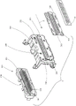
fig. 1 shows an exploded illustration of an exemplary optical device having a holder and a cover element, wherein a projection projecting from the holder is designed to engage in a guide receptacle of the cover element in order to connect the holder to the cover element,
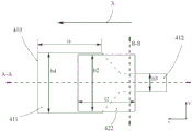
figure 2A shows a schematic detail view of the guide receptacle and the projection in a top view,
figure 2B shows a cross-sectional view along section a-a from the illustration of figure 5A,
figure 2C shows a cross-sectional view along section plane B-B from the illustration of figure 5B,
figure 3 shows a perspective view of the optical device from figure 1 in the assembled state,
FIG. 4 shows a rear view of the optical device from FIG. 3, an
Fig. 5 shows a side view of the optical arrangement from fig. 4 with the light sources arranged.
Detailed Description
Fig. 1 shows an exemplary optical device 1 in an exploded illustration, wherein a plurality of light sources 10 are arranged on the rear side of the device 1, said light sources being designed to emit light in a main emission direction.
Furthermore, device 1 comprises a holder 200, on which base body 101 of primary optical system 100 is arranged or can be fixed on the front side of holder 200, light conductor 110 of the primary optical system passing through holder 200 via opening region 210 of holder 200.
Furthermore, device 1 comprises a cover element 300 which is arranged on the rear side of base body 101 of holder 200 facing away from primary optical element 100 and has a thickness d1, preferably a constant thickness, wherein cover element 300 has a number of openings 310 corresponding to the number of light conductors 110 and corresponding to light conductors 110, openings 310 being provided for receiving light conductors 110 of primary optical element 100 and holding them in position.
In the example shown, the cover element 300 can be connected to the holder 200 by means of five first engagement elements 410 arranged on the cover element 300, which are respectively provided for engagement at second engagement elements 420 arranged on the holder 200.
In the embodiment shown in the figures, the second engagement element 420 is configured correspondingly as a projection 420 projecting from the holder 200 and the first engagement element 410 is configured as a guide recess 410 in the cover element 300. Fig. 2A, 2B and 2C each show a detail view of a connectable joining element.
As is more clearly visible, for example, in fig. 2A, the projection 420 furthermore has an engagement section 421 with a height h1 extending away from the holder 200 and a width b1, and an end section 422 with a height h2 and a width b2 and a length l 2. In the illustrated embodiment, the width b1 of the engagement section 421 is less than the width b2 of the end section 422.
Each guide notch 410 has a first region 411 with a width b4 and a length l4 and a second region 412 which tapers compared to the first region 411, the second region 412 extending along the push-up direction X and having a width b3 running transversely to the push-up direction X, as can be seen in fig. 2A.
The projection 420 or its end section 422 can be correspondingly guided through the first region 411 of the guide recess 410, so that the second region 412 of the guide recess 410 can be pushed up onto the engagement section 421 of the projection 420 by means of a displacement of the cover element 300 in the push-up direction X, wherein the width b3 of the second region 412 of the guide recess 410 corresponds at least to the width b1 of the engagement section 421 of the projection 420, and wherein the height h1 of the engagement section 421 of the projection 420 corresponds at least to the thickness d1 of the cover element 300, preferably to the thickness in the region of the guide recess 410 of the cover element 300.
Furthermore, the width b2 and the length l2 of the end section 422 of the projection 420 are at least slightly smaller than the width b4 and the length l4 of the first region 411 of the guide notch 410.
Fig. 2A shows this with the engagement section 421 of the projection 420 partially pushed up into the second region 412 of the guide recess 410. Fig. 2B shows a cross-sectional view along the sectional plane a-a from the illustration in fig. 2A, wherein it can be recognized that the end section 422 of the projection 420 has a tapering relative to the push-up direction X with respect to its height h 2.
Furthermore, it can be seen in fig. 2B or in fig. 2C that two thickening elements 423 are arranged on the side of the end section 422 of the projection 420 opposite the cover element 300 in the pushed-up state of the cover element 300, wherein the spacing h3 between the holder 200 and at least one thickening element 423 is smaller than the height h1 of the engagement section 421 of the projection 420, which is depicted, for example, in fig. 2C, which fig. 2C shows a sectional view along the sectional plane B-B from the illustration in fig. 2A.
Fig. 3 and 4 each show an assembled state of the optical device 1, in which the cover element 300 is connected to the holder 200 or pushed completely onto the holder 200.
In the example shown, the holder 200 has two stop elements 210, which stop elements 210 are designed to limit the displacement of the cover element 300 in the push-up direction X. The stop element 210 is arranged on the holder 200, for example, in such a way that an outer edge region or a closing edge of the cover element 300 rests or stops against the stop element 210 in the fully pushed-up state of the cover element 300.
Furthermore, a latching projection 220 is arranged on the holder 200, said latching projection being designed to engage in a fastening recess 320 corresponding to the latching projection 220, said fastening recess being provided on the cover element 300.
Fig. 5 shows a side view of the assembled optical device 1, wherein a light source 10 as already mentioned at the outset is additionally shown.
List of reference numerals
Optical device … 1
Light source … 10
Primary optical mechanism … 100
Substrate … 101
Light conductor … 110
Light entrance surface … 120
Light exit surface … 130
Holder … 200
Opening region … 201
Stop element … 210
Latch tab … 220
Covering element … 300
Opening … 310
Securing notch … 320
Guide notch … 410
First region … 411
Second region … 412
Protrusion … 420
Engaging section … 421
End section … 422
Thickening element … 423
Pushing up direction … X.
Claims (13)
1. Optical device (1) for a motor vehicle headlight, wherein the device comprises the following components:
a primary optical unit (100) having a base body (101) and having a plurality of light conductors (110) projecting from the base body for forming a desired light distribution from the light of a light source, each light conductor having a light entry face (120) into which the light of the light source can be fed and a light exit face (130),
-a holder (200) at which a base body (101) of the primary optical mechanism (100) is arranged on a front side of the holder (200), wherein a light conductor (110) of the primary optical mechanism passes through the holder (200) through an opening region (201) of the holder, and
a cover element (300) which is arranged on the rear side of the base body (101) of the holder (200) facing away from the primary optical means (100), wherein the cover element (300) has a number of openings (310) corresponding to the number of light conductors (10) and corresponding to the light conductors, the openings (310) being designed to receive the light conductors (110) of the primary optical means (100) and to hold them in position, wherein the cover element (300) can be connected to the holder by means of at least one first engagement element arranged on the cover element (300) which engages at least one second engagement element arranged on the holder (200),
it is characterized in that the preparation method is characterized in that,
the at least one second engagement element is configured as a projection (420) projecting from the holder (200), the projection having an engagement section (421) with a height (h 1) and a width (b 1) extending away from the holder (200) and having an end section (422) with a height (h 2) and a width (b 2),
and wherein the at least one first engaging element is designed as a guide recess (410) in the cover element (300), wherein the guide recess (410) has a first region (411) and a second region (412) which tapers in comparison to the first region, wherein the second region (412) extends along a push-up direction (X) and has a width (b 3) which runs transversely to the push-up direction (X), wherein the projection (420) can be inserted into the first region (411) of the guide recess (410) and can be displaced within the guide recess (410) such that the second region (412) of the guide recess (410) can be pushed up onto an engaging section (421) of the projection (420) by means of a displacement of the cover element (300) in the push-up direction (X).
2. Device (1) according to claim 1, characterized in that the width (b 1) of the engagement section (421) is smaller than the width (b 2) of the end section (422).
3. Device (1) according to claim 1 or 2, characterized in that the width (b 3) of the second region (412) of the guide notch (410) corresponds at least to the width (b 1) of the engagement section (421) of the projection (420).
4. Device (1) according to any one of claims 1 to 3, characterized in that the end section (422) of the projection (420) has, with respect to its height (h 2), a taper with respect to the push-up direction (X).
5. Device (1) according to one of claims 1 to 4, characterized in that the cover element (300) has a thickness (d 1), wherein the height (h 1) of the engagement section (421) of the projection (420) corresponds at least to the thickness (d 1) of the cover element (300), preferably to the thickness in the region of the guide recess (410) of the cover element (300).
6. Device (1) according to one of claims 1 to 5, characterized in that the holder (200) has at least one stop element (210), the stop element (210) being set up for limiting a displacement of the cover element (300) in the direction of the push-up direction (X), wherein preferably at least two stop elements (210) are provided.
7. Device (1) according to any one of claims 1 to 6, characterized in that at least two first coupling elements (410) and at least two second coupling elements (420) corresponding to the first coupling elements (410) are provided.
8. Device (1) according to one of claims 1 to 7, characterized in that at least one thickening element (423) is arranged on the side of an end section (422) of the projection (420) facing the holder (200), wherein the spacing between the holder (200) and the at least one thickening element (423) is smaller than the height (h 1) of an engagement section (421) of the projection (420), wherein preferably at least two thickening elements (423) are arranged on the end section.
9. Device (1) according to one of claims 1 to 8, characterized in that at least one latching lug (220) is arranged on the holder (200), which latching lug is set up for snapping into a fixing recess (320) corresponding to the latching lug (220), which is provided at the covering element (300).
10. Illumination device having at least one optical device (1) according to one of claims 1 to 9 and a number of light sources (10) emitting light corresponding to the number of light conductors (110), which light is provided for feeding into the at least one optical device (1).
11. A lighting device as claimed in claim 10, characterized in that exactly one or at least one light source is assigned to each light conductor (110).
12. Light module having at least one lighting device according to claim 10 or 11.
13. Motor vehicle headlight with at least one lighting device according to claim 10 or 11 and/or at least one light module according to claim 12.
Applications Claiming Priority (3)
| Application Number | Priority Date | Filing Date | Title |
|---|---|---|---|
| EP18187242.5 | 2018-08-03 | ||
| EP18187242.5A EP3604902A1 (en) | 2018-08-03 | 2018-08-03 | Optical device for a motor vehicle headlight comprising light guides |
| PCT/EP2019/068786 WO2020025291A1 (en) | 2018-08-03 | 2019-07-12 | Optical device for a motor vehicle headlight comprising optical waveguides |
Publications (1)
| Publication Number | Publication Date |
|---|---|
| CN112469940A true CN112469940A (en) | 2021-03-09 |
Family
ID=63144884
Family Applications (1)
| Application Number | Title | Priority Date | Filing Date |
|---|---|---|---|
| CN201980051448.7A Pending CN112469940A (en) | 2018-08-03 | 2019-07-12 | Optical device for a motor vehicle headlight with a light guide |
Country Status (6)
| Country | Link |
|---|---|
| US (1) | US11248765B2 (en) |
| EP (2) | EP3604902A1 (en) |
| JP (1) | JP6999065B2 (en) |
| KR (1) | KR102506798B1 (en) |
| CN (1) | CN112469940A (en) |
| WO (1) | WO2020025291A1 (en) |
Families Citing this family (1)
| Publication number | Priority date | Publication date | Assignee | Title |
|---|---|---|---|---|
| EP4001073A1 (en) * | 2020-11-17 | 2022-05-25 | ZKW Group GmbH | Optical device for a motorcycle headlamp optics |
Citations (5)
| Publication number | Priority date | Publication date | Assignee | Title |
|---|---|---|---|---|
| TWM371833U (en) * | 2009-09-09 | 2010-01-01 | Forward Electronics Co Ltd | LED module structure |
| CN103574464A (en) * | 2012-08-03 | 2014-02-12 | 汽车照明罗伊特林根有限公司 | Primary optical unit for a light module |
| CN103717962A (en) * | 2011-08-08 | 2014-04-09 | 齐扎拉光系统有限责任公司 | Led light-source module for a vehicle headlight |
| CN104713009A (en) * | 2013-12-13 | 2015-06-17 | 汽车照明罗伊特林根有限公司 | Motor vehicle headlamp |
| CN108204570A (en) * | 2016-12-19 | 2018-06-26 | 汽车照明罗伊特林根有限公司 | For the primary optical component being mounted in lighting assembly for vehicles and the lighting assembly for vehicles with this primary optical component |
Family Cites Families (10)
| Publication number | Priority date | Publication date | Assignee | Title |
|---|---|---|---|---|
| US7329887B2 (en) * | 2003-12-02 | 2008-02-12 | 3M Innovative Properties Company | Solid state light device |
| FR2982006B1 (en) * | 2011-09-13 | 2018-04-27 | Valeo Vision | OPTICAL MODULE WITH COMMON REFERENCE FOR LIGHTING AND / OR SIGNALING OF A MOTOR VEHICLE |
| AT512865B1 (en) * | 2012-05-09 | 2014-12-15 | Zizala Lichtsysteme Gmbh | Lighting device for a motor vehicle headlight and light module and motor vehicle headlight with lighting device |
| DE102012106314A1 (en) * | 2012-07-13 | 2014-01-16 | Hella Kgaa Hueck & Co. | Module assembly with pivotable semiconductor light modules for a headlight |
| AT513206B1 (en) * | 2012-07-18 | 2015-04-15 | Zizala Lichtsysteme Gmbh | Lighting unit for a headlight |
| DE102015103649B4 (en) | 2015-03-12 | 2022-09-29 | HELLA GmbH & Co. KGaA | Light module with adjustment means between a light source and an optical element |
| JP6769704B2 (en) | 2015-11-30 | 2020-10-14 | 株式会社小糸製作所 | Vehicle lighting |
| KR102518368B1 (en) * | 2016-04-06 | 2023-04-13 | 삼성전자주식회사 | Lighting apparatus |
| DE102017204527B4 (en) * | 2017-03-17 | 2022-06-09 | Osram Gmbh | Lighting system and headlights |
| DE102017209815A1 (en) * | 2017-06-09 | 2018-12-13 | Osram Gmbh | LIGHTING DEVICE FOR A HEADLAMP OF A VEHICLE, HEADLAMP, LIGHT SYSTEM, VEHICLE AND METHOD |
-
2018
- 2018-08-03 EP EP18187242.5A patent/EP3604902A1/en not_active Withdrawn
-
2019
- 2019-07-12 EP EP19742151.4A patent/EP3830472B1/en active Active
- 2019-07-12 US US17/264,425 patent/US11248765B2/en active Active
- 2019-07-12 JP JP2021505877A patent/JP6999065B2/en active Active
- 2019-07-12 CN CN201980051448.7A patent/CN112469940A/en active Pending
- 2019-07-12 KR KR1020217005374A patent/KR102506798B1/en active IP Right Grant
- 2019-07-12 WO PCT/EP2019/068786 patent/WO2020025291A1/en unknown
Patent Citations (5)
| Publication number | Priority date | Publication date | Assignee | Title |
|---|---|---|---|---|
| TWM371833U (en) * | 2009-09-09 | 2010-01-01 | Forward Electronics Co Ltd | LED module structure |
| CN103717962A (en) * | 2011-08-08 | 2014-04-09 | 齐扎拉光系统有限责任公司 | Led light-source module for a vehicle headlight |
| CN103574464A (en) * | 2012-08-03 | 2014-02-12 | 汽车照明罗伊特林根有限公司 | Primary optical unit for a light module |
| CN104713009A (en) * | 2013-12-13 | 2015-06-17 | 汽车照明罗伊特林根有限公司 | Motor vehicle headlamp |
| CN108204570A (en) * | 2016-12-19 | 2018-06-26 | 汽车照明罗伊特林根有限公司 | For the primary optical component being mounted in lighting assembly for vehicles and the lighting assembly for vehicles with this primary optical component |
Also Published As
| Publication number | Publication date |
|---|---|
| EP3830472B1 (en) | 2023-03-15 |
| EP3604902A1 (en) | 2020-02-05 |
| US11248765B2 (en) | 2022-02-15 |
| JP6999065B2 (en) | 2022-02-04 |
| KR102506798B1 (en) | 2023-03-07 |
| EP3830472A1 (en) | 2021-06-09 |
| JP2021532560A (en) | 2021-11-25 |
| WO2020025291A1 (en) | 2020-02-06 |
| KR20210035260A (en) | 2021-03-31 |
| US20210310627A1 (en) | 2021-10-07 |
Similar Documents
| Publication | Publication Date | Title |
|---|---|---|
| CN108626677B (en) | Lighting system and headlamp | |
| JP6202286B2 (en) | Lighting equipment for automotive headlamps | |
| US9803825B2 (en) | Lighting device for a vehicle headlight | |
| EP1954981B1 (en) | Semiconductor-based lighting systems and lighting system components for automotive use | |
| US9116280B2 (en) | Holding frame for an optical element | |
| CN108204570B (en) | Primary optical assembly for installation in a motor vehicle lighting device and motor vehicle lighting device having such a primary optical assembly | |
| CN108139059A (en) | The headlamp of headlamp, especially motor vehicle | |
| CN112166283B (en) | Lighting device for motor vehicle headlight | |
| US20120281418A1 (en) | Reflector for a Lighting Device and Lighting Device | |
| JP2015524600A (en) | Lighting unit for headlamp | |
| US11435046B2 (en) | Illumination system for a lighting and/or signalling device of a motor vehicle | |
| US11118751B2 (en) | Lighting device with transparent stabilizer element | |
| JP2018032618A (en) | Vehicle light device with optical element pinned with flexible bracing element | |
| US10551009B2 (en) | Lighting module comprising at least one removable light source | |
| CN112469940A (en) | Optical device for a motor vehicle headlight with a light guide | |
| US20190063708A1 (en) | Lighting system, headlamp, and method for producing a lighting system | |
| CN211530315U (en) | Combination structure | |
| CN113958920A (en) | Lighting device for a motor vehicle headlight | |
| US10486588B2 (en) | Lighting module for automotive vehicle | |
| US11614213B2 (en) | Projection assembly for a motor vehicle headlight | |
| CN112005046A (en) | Vehicle lamp | |
| CN108351307A (en) | For preparing the lighting unit that equipment identifies the equipment of impurity for weaving | |
| KR20200138660A (en) | Illumination device for a motor vehicle headlamp | |
| CN115698586A (en) | Attachment optical assembly for a partial high beam module of a motor vehicle headlamp | |
| CN117813465A (en) | Lighting device for motor vehicle headlight |
Legal Events
| Date | Code | Title | Description |
|---|---|---|---|
| PB01 | Publication | ||
| PB01 | Publication | ||
| SE01 | Entry into force of request for substantive examination | ||
| SE01 | Entry into force of request for substantive examination |