CN112469552B - Method and apparatus for producing a continuous semifinished product, downhole heat exchanger, wellbore reinforcement and rehabilitating pipe - Google Patents
Method and apparatus for producing a continuous semifinished product, downhole heat exchanger, wellbore reinforcement and rehabilitating pipe Download PDFInfo
- Publication number
- CN112469552B CN112469552B CN201980049040.6A CN201980049040A CN112469552B CN 112469552 B CN112469552 B CN 112469552B CN 201980049040 A CN201980049040 A CN 201980049040A CN 112469552 B CN112469552 B CN 112469552B
- Authority
- CN
- China
- Prior art keywords
- hose
- silicone
- continuous
- continuous fiber
- silicone hose
- Prior art date
- Legal status (The legal status is an assumption and is not a legal conclusion. Google has not performed a legal analysis and makes no representation as to the accuracy of the status listed.)
- Active
Links
Images


Classifications
-
- B—PERFORMING OPERATIONS; TRANSPORTING
- B29—WORKING OF PLASTICS; WORKING OF SUBSTANCES IN A PLASTIC STATE IN GENERAL
- B29C—SHAPING OR JOINING OF PLASTICS; SHAPING OF MATERIAL IN A PLASTIC STATE, NOT OTHERWISE PROVIDED FOR; AFTER-TREATMENT OF THE SHAPED PRODUCTS, e.g. REPAIRING
- B29C70/00—Shaping composites, i.e. plastics material comprising reinforcements, fillers or preformed parts, e.g. inserts
- B29C70/04—Shaping composites, i.e. plastics material comprising reinforcements, fillers or preformed parts, e.g. inserts comprising reinforcements only, e.g. self-reinforcing plastics
- B29C70/06—Fibrous reinforcements only
- B29C70/08—Fibrous reinforcements only comprising combinations of different forms of fibrous reinforcements incorporated in matrix material, forming one or more layers, and with or without non-reinforced layers
- B29C70/086—Fibrous reinforcements only comprising combinations of different forms of fibrous reinforcements incorporated in matrix material, forming one or more layers, and with or without non-reinforced layers and with one or more layers of pure plastics material, e.g. foam layers
-
- B—PERFORMING OPERATIONS; TRANSPORTING
- B29—WORKING OF PLASTICS; WORKING OF SUBSTANCES IN A PLASTIC STATE IN GENERAL
- B29C—SHAPING OR JOINING OF PLASTICS; SHAPING OF MATERIAL IN A PLASTIC STATE, NOT OTHERWISE PROVIDED FOR; AFTER-TREATMENT OF THE SHAPED PRODUCTS, e.g. REPAIRING
- B29C70/00—Shaping composites, i.e. plastics material comprising reinforcements, fillers or preformed parts, e.g. inserts
- B29C70/04—Shaping composites, i.e. plastics material comprising reinforcements, fillers or preformed parts, e.g. inserts comprising reinforcements only, e.g. self-reinforcing plastics
- B29C70/28—Shaping operations therefor
- B29C70/40—Shaping or impregnating by compression not applied
- B29C70/50—Shaping or impregnating by compression not applied for producing articles of indefinite length, e.g. prepregs, sheet moulding compounds [SMC] or cross moulding compounds [XMC]
- B29C70/52—Pultrusion, i.e. forming and compressing by continuously pulling through a die
-
- B—PERFORMING OPERATIONS; TRANSPORTING
- B29—WORKING OF PLASTICS; WORKING OF SUBSTANCES IN A PLASTIC STATE IN GENERAL
- B29D—PRODUCING PARTICULAR ARTICLES FROM PLASTICS OR FROM SUBSTANCES IN A PLASTIC STATE
- B29D23/00—Producing tubular articles
- B29D23/001—Pipes; Pipe joints
-
- B—PERFORMING OPERATIONS; TRANSPORTING
- B29—WORKING OF PLASTICS; WORKING OF SUBSTANCES IN A PLASTIC STATE IN GENERAL
- B29K—INDEXING SCHEME ASSOCIATED WITH SUBCLASSES B29B, B29C OR B29D, RELATING TO MOULDING MATERIALS OR TO MATERIALS FOR MOULDS, REINFORCEMENTS, FILLERS OR PREFORMED PARTS, e.g. INSERTS
- B29K2683/00—Use of polymers having silicon, with or without sulfur, nitrogen, oxygen or carbon only, in the main chain, for preformed parts, e.g. for inserts
-
- Y—GENERAL TAGGING OF NEW TECHNOLOGICAL DEVELOPMENTS; GENERAL TAGGING OF CROSS-SECTIONAL TECHNOLOGIES SPANNING OVER SEVERAL SECTIONS OF THE IPC; TECHNICAL SUBJECTS COVERED BY FORMER USPC CROSS-REFERENCE ART COLLECTIONS [XRACs] AND DIGESTS
- Y02—TECHNOLOGIES OR APPLICATIONS FOR MITIGATION OR ADAPTATION AGAINST CLIMATE CHANGE
- Y02E—REDUCTION OF GREENHOUSE GAS [GHG] EMISSIONS, RELATED TO ENERGY GENERATION, TRANSMISSION OR DISTRIBUTION
- Y02E10/00—Energy generation through renewable energy sources
- Y02E10/10—Geothermal energy
Landscapes
- Engineering & Computer Science (AREA)
- Mechanical Engineering (AREA)
- Chemical & Material Sciences (AREA)
- Composite Materials (AREA)
- Rigid Pipes And Flexible Pipes (AREA)
- Lining Or Joining Of Plastics Or The Like (AREA)
Abstract
一种用于生产连续半成品(10)的方法,包括以下步骤:供应硅氧烷软管(12)和单独的内部导体(11),其中所述内部导体(11)在由所述硅氧烷软管(12)形成的第一内部空间(12a)中延伸;通过生产在外部包围所述硅氧烷软管(12)的连续纤维软管(13)包覆所供应的硅氧烷软管(12);张开所述硅氧烷软管(12),以使在所述硅氧烷软管(12)与所述连续纤维软管(13)之间形成间隙(14);将基质材料供应入所述间隙(14)中;通过硬化所述基质材料,将所述硅氧烷软管(12)和所述连续纤维软管(13)结合在一起。

A method for producing a continuous semi-finished product (10), comprising the steps of supplying a silicone hose (12) and a separate inner conductor (11), wherein said inner conductor (11) is extends in the first inner space (12a) formed by the hose (12); the supplied silicone hose is clad by producing a continuous fiber hose (13) which surrounds said silicone hose (12) on the outside (12); Stretching the silicone hose (12) so that a gap (14) is formed between the silicone hose (12) and the continuous fiber hose (13); Material is supplied into said gap (14); said silicone hose (12) and said continuous fiber hose (13) are bonded together by hardening said matrix material.
Description
技术领域technical field
本发明涉及用于生产连续半成品的方法和设备、连续半成品、井下换热器、井眼增强件和修复管。The present invention relates to methods and apparatus for producing continuous semi-finished products, continuous semi-finished products, downhole heat exchangers, wellbore reinforcements and repair tubing.
背景技术Background technique
房屋建设拥堵加剧的结果是经常在有地下水的地区中架设有结构体。为了以节能方式对建筑物进行加热和冷却,特别是为了减少二氧化碳排放,借助使用井下换热器的热泵进行的热量产生和/或制冷越来越重要。这种井下换热器需要在地下通常具有50-500米深度的井眼。然而,为了保护地下水,存在极其严格的规定,其结果是通常不允许在存在地下水的地区中架设井下换热器。因此,需要一种划算的系统,该系统可消除由于结构体特别是到达地下的井下换热器而污染地下水或其它类型污染物的风险。As a result of increased housing construction congestion, structures are often erected in areas with groundwater. In order to heat and cool buildings in an energy-efficient manner, in particular to reduce carbon dioxide emissions, heat generation and/or cooling by means of heat pumps using downhole heat exchangers is becoming increasingly important. Such a downhole heat exchanger requires a wellbore in the ground, typically at a depth of 50-500 metres. However, there are extremely strict regulations in order to protect groundwater, with the result that downhole heat exchangers are generally not permitted to be erected in areas where groundwater is present. Therefore, there is a need for a cost-effective system that eliminates the risk of contaminating ground water or other types of pollutants due to structures, particularly downhole heat exchangers that reach the subsurface.
文献WO2013/170389A2公开了一种具有可膨胀管状外壳的井下换热器。所述外壳对水具有有限的渗透性,使得在井下换热器内部循环的液体会污染地下水。文献WO2017/016790A1同样公开了一种井下换热器。所述井下换热器还不能确保对水和/或液体的保证不渗透性。文献DE102012201262A1公开了一种用于制造坚固的、尺寸稳定的中空型材的方法。这种尺寸稳定的中空型材不适合用作井下换热器。因此,仍然需要一种安全且具有成本效益的系统,该系统适用于井下换热器和其它土木工程结构,特别是存在地下水的地区中的土木工程结构。Document WO2013/170389A2 discloses a downhole heat exchanger with an expandable tubular casing. The shell has limited permeability to water so that liquid circulating inside the downhole heat exchanger can contaminate the ground water. Document WO2017/016790A1 also discloses a downhole heat exchanger. Said downhole heat exchangers do not yet ensure guaranteed impermeability to water and/or liquids.
发明内容Contents of the invention
本发明的一个目的是提供用于生产连续半成品的方法和设备、连续半成品、井下换热器、井眼增强件和修复管,其解决了现有技术的缺点。It is an object of the present invention to provide a method and an apparatus for producing continuous semi-finished products, continuous semi-finished products, downhole heat exchangers, wellbore reinforcements and rehab tubulars, which solve the disadvantages of the prior art.
所述目的通过具有根据权利要求1的特征的方法实现。从属权利要求2至7涉及进一步有利的方法步骤。该目的还通过具有根据权利要求8的特征的设备实现。从属权利要求9至10涉及进一步有利的构造。该目的还通过连续半成品实现,该连续半成品通过根据本发明的方法生产。该目的还通过包括连续半成品的井下换热器、井眼增强件或修复管实现。This object is achieved by a method having the features according to claim 1 . Dependent claims 2 to 7 relate to further advantageous method steps. This object is also achieved by a device having the features according to
该目的尤其通过一种用于生产连续半成品的方法实现,该方法包括:供应硅氧烷软管和单独的内部导体,其中内部导体在由硅氧烷软管形成的第一内部空间中延伸;通过生产连续纤维软管来包覆所供应的硅氧烷软管,该纤维软管在外部包围硅氧烷软管;张开硅氧烷软管,以使硅氧烷软管与连续纤维软管之间形成间隙;将基质材料供应到间隙中;和通过硬化基质材料将硅氧烷软管和连续纤维软管结合在一起。This object is achieved in particular by a method for producing a continuous semi-finished product, the method comprising: supplying a silicone hose and a separate inner conductor, wherein the inner conductor extends in a first inner space formed by the silicone hose; Clad the supplied silicone hose by producing a continuous fiber hose that externally surrounds the silicone hose; A gap is formed between the tubes; a matrix material is supplied into the gap; and the silicone hose and the continuous fiber hose are bonded together by hardening the matrix material.
该目的另外特别地通过一种用于生产连续半成品的设备来实现,该设备包括:This object is additionally achieved in particular by a plant for the production of continuous semi-finished products comprising:
输送装置,其用于供应硅氧烷软管和布置在硅氧烷软管内部的内部导体;delivery device for supplying the silicone hose and the inner conductor arranged inside the silicone hose;
结合装置,其用于结合多根纤维以形成连续纤维软管,并且用该连续纤维软管将所供应的硅氧烷软管包覆起来;bonding means for bonding a plurality of fibers to form a continuous fiber hose and wrapping the supplied silicone hose with the continuous fiber hose;
张开装置,其用于张开硅氧烷软管并减小连续纤维软管与硅氧烷软管之间的间隙;a splay device for splaying the silicone hose and reducing the gap between the continuous fiber hose and the silicone hose;
供应装置,其用于将液体结合剂供应到所述间隙中;和交联装置,其用于使结合剂交联并将硅氧烷软管结合至连续纤维软管。supply means for supplying a liquid adhesive into the gap; and crosslinking means for crosslinking the adhesive and bonding the silicone hose to the continuous fiber hose.
根据本发明的连续半成品具有的优点在于:硅氧烷软管,当然特别还有包覆硅氧烷软管的连续纤维软管,以及结合硅氧烷软管和连续纤维软管的基质材料,仅由从防水角度来看安全的材料组成。所述材料优选是食品安全的和/或符合食品要求的。因为硅氧烷软管是在第一方法步骤中与连续纤维软管分开生产的,所以可以在生产过程中检查和/或确保硅氧烷软管已经是流体密封的。以连续纤维软管包覆硅氧烷软管的后续方法步骤不再影响硅氧烷软管的流体密封性,特别是液密性。因此,在根据本发明的连续半成品中,确保了由硅氧烷软管形成的内部空间以绝对水密和/或流体密封的方式与其外部空间分隔开。由连续半成品生产的最终产品例如井下换热器、井眼增强件或修复管因此也可以毫无问题地用于土木工程结构中,特别是与地下水直接接触的部件。因此,例如可能保证井下换热器的水密性,因此即使在存在地下水的地区中,也可能长期安全地使用根据本发明的井下换热器。如果需要的话,也有可能获得根据本发明的最终产品的官方授权,以允许其在存在地下水的地区中使用。The continuous semi-finished product according to the invention has the advantage that the silicone hose, and of course in particular the continuous fiber hose coated with the silicone hose, and the matrix material combining the silicone hose and the continuous fiber hose, Consists only of materials that are safe from a waterproofing point of view. The material is preferably food-safe and/or food-compliant. Since the silicone hose is produced separately from the continuous fiber hose in the first method step, it is possible to check and/or ensure that the silicone hose is already fluid-tight during production. The subsequent method steps of covering the silicone tube with the continuous fiber tube no longer affect the fluid-tightness, in particular liquid-tightness, of the silicone tube. Thus, in the continuous semi-finished product according to the invention it is ensured that the inner space formed by the silicone hose is separated from its outer space in an absolutely watertight and/or fluid-tight manner. End products produced from continuous semi-finished products, such as downhole heat exchangers, borehole reinforcements or rehabilitation pipes, can thus also be used without problems in civil engineering structures, especially components that come into direct contact with groundwater. Thus, for example, it is possible to ensure the watertightness of the downhole heat exchanger, so that it is possible to use the downhole heat exchanger according to the invention safely for a long time even in areas where groundwater exists. It is also possible, if required, to obtain official authorization of the end product according to the invention, allowing its use in areas where groundwater exists.
由根据本发明的连续半成品生产的最终产品当然也可以用于不存在地下水的地区,这带来的优点是无论是否存在水,这种产品都可以在整个建设过程中基本使用,因此可以省去不同的产品,从而可以实现更具成本效益的生产和明显更有利的销售。The end product produced from the continuous semi-finished product according to the invention can of course also be used in areas where groundwater does not exist, which brings the advantage that this product can basically be used throughout the construction process regardless of the presence or absence of water, thus eliminating the need for different products, which allow for more cost-effective production and significantly more profitable sales.
根据本发明的连续半成品基本上通过两步方法生产,第一步方法,其中生产硅氧烷软管和布置在其中的内部导体,第二步方法,其中在所述硅氧烷软管周围施加沿圆周方向包围硅氧烷软管的连续纤维软管,并且硅氧烷软管在其外侧上与连续纤维软管结合。硅氧烷软管是通过挤出方法生产的,该生产方法可确保所生产的硅氧烷软管是流体密封的。The continuous semi-finished product according to the invention is essentially produced by a two-step process, a first step process in which the silicone hose and the inner conductor arranged therein are produced, a second step process in which the silicone hose is applied around said silicone hose The continuous fiber hose surrounds the silicone hose in the circumferential direction, and the silicone hose is combined with the continuous fiber hose on its outer side. Silicone hoses are produced by an extrusion method which ensures that the silicone hoses produced are fluid-tight.
硅氧烷软管应理解为是指由硅氧烷组成的软管,该硅氧烷在化学上更准确地称为聚(有机)硅氧烷,这是一组合成聚合物的名称,其中硅原子通过氧原子结合。这种硅氧烷软管的优点在于它耐高温、柔软、耐气候性和耐老化,并且另外还耐降解并且以无毒的方式降解。这种硅氧烷软管具有高绝缘强度、耐稀酸和碱、食品安全和/或符合食品要求并且耐臭氧,因此也不会将任何污染物质排放到环境中,特别是不排放到存在的任何地下水中。与其它食品安全性塑料(如聚乙烯(PE)或聚丙烯(PP)或聚四氟乙烯)相对牢固和坚硬相比,硅氧烷是保持弹性的材料。Silicone hoses are understood to mean hoses composed of silicones, which are chemically more precisely known as poly(organo)siloxanes, the name given to a group of synthetic polymers in which Silicon atoms are bonded via oxygen atoms. The advantage of this silicone hose is that it is temperature-resistant, flexible, weather-resistant and age-resistant, and is also resistant to degradation and degrades in a non-toxic manner. This silicone hose has high dielectric strength, is resistant to dilute acids and alkalis, is food-safe and/or food-compliant and ozone-resistant, and therefore also does not emit any polluting substances into the environment, especially into the presence of any groundwater. Silicone is a resilient material compared to the relative strength and rigidity of other food-safe plastics such as polyethylene (PE) or polypropylene (PP) or Teflon.
纤维软管应理解为是指由纤维制成的软管。所使用的纤维包括例如聚酯、聚酰胺、聚乙烯或芳族聚酰胺并且特别有利地由聚酯组成。纤维软管可以通过织造、编织、通过成圈针织或通过引圈针织来生产。如果纤维软管借助于圆形编织被制成连续纤维软管,则是特别有利的。为此,将硅氧烷软管插入到圆形编织的中心,并沿着硅氧烷软管的外表面延伸出连续纤维软管,从而连续纤维软管形成在圆周方向上围绕硅氧烷软管的织物。A fiber hose is understood to mean a hose made of fibers. The fibers used include, for example, polyester, polyamide, polyethylene or aramid and particularly advantageously consist of polyester. Fiber hoses can be produced by weaving, braiding, by loop knitting or by loop knitting. It is particularly advantageous if the fiber hose is produced as a continuous fiber hose by means of circular braiding. To this end, the silicone hose is inserted into the center of the circular braid, and the continuous fiber hose is extended along the outer surface of the silicone hose, so that the continuous fiber hose is formed around the silicone soft tube in the circumferential direction. Tube of fabric.
硅氧烷软管尤其具有确保流体密封性,尤其是水密性的功能。包围硅氧烷软管的连续纤维软管尤其具有接收和保持作用在硅氧烷软管的壁上的力的功能。另外,连续纤维软管具有例如保护硅氧烷软管的外皮免受机械损坏的功能。硅氧烷软管的弹性特性带来的优点是,它可以在制造根据本发明的连续半成品期间毫无问题地张开,特别是为了将硅氧烷软管的外表面优选遍布表面区域结合到连续纤维软管。因此,硅氧烷软管的弹性确保了它在结合到连续纤维软管时不会撕裂,并且硅氧烷软管可以根据连续纤维软管的制造公差灵活地进行调整,因此即使完成了连续半成品,也可以确保硅氧烷软管是流体密封的。如果硅氧烷软管未在整个表面区域结合到连续纤维软管,硅氧烷软管的弹性特性带来的优点在于,硅氧烷软管在现有的内部压力下会张开,直到硅氧烷软管贴靠连续纤维软管的内侧,使得作用在硅氧烷软管内部的压力就可以通过硅氧烷软管壁可靠地传递到连续纤维软管,而没有硅氧烷软管可能会出现不允许的薄点甚至撕裂的风险。硅氧烷软管和连续纤维软管的组合确保了本发明的连续半成品长期可靠的流体密封性,确保了符合食品要求,还可以承受较高的内部压力,例如最高120巴或最高200巴,它也可以在恶劣的建设环境中使用。因此,根据本发明的连续半成品最适合用于生产井下换热器,这种井下换热器和/或用于此目的连续半成品的长度优选在50-500米之间。Silicone hoses in particular have the function of ensuring fluid-tightness, especially watertightness. The continuous fiber hose surrounding the silicone hose has, inter alia, the function of absorbing and maintaining the forces acting on the walls of the silicone hose. In addition, the continuous fiber hose has the function of, for example, protecting the sheath of the silicone hose from mechanical damage. The elastic properties of the silicone hose have the advantage that it can be opened without problems during the manufacture of the continuous semi-finished product according to the invention, in particular for bonding the outer surface of the silicone hose, preferably over the surface area, to the Continuous fiber hose. Therefore, the elasticity of the silicone hose ensures that it will not tear when bonded to the continuous fiber hose, and the silicone hose can be flexibly adjusted according to the manufacturing tolerances of the continuous fiber hose, so even if the continuous fiber hose is completed Semi-finished products also ensure that silicone hoses are fluid-tight. If the silicone hose is not bonded to the continuous fiber hose over the entire surface area, the elastic nature of the silicone hose has the advantage that the silicone hose will expand under the existing internal pressure until the silicon The oxane hose is attached to the inner side of the continuous fiber hose, so that the pressure acting on the inside of the silicone hose can be reliably transmitted to the continuous fiber hose through the silicone hose wall, which is not possible with silicone hose. There is a risk of impermissible thin spots or even tears. The combination of silicone hose and continuous fiber hose ensures long-term reliable fluid tightness of the continuous semi-finished product according to the invention, ensures compliance with food requirements and can also withstand higher internal pressures, e.g. up to 120 bar or up to 200 bar, It can also be used in harsh construction environments. Therefore, the continuous semi-finished product according to the invention is most suitable for the production of downhole heat exchangers, the length of which and/or the continuous semi-finished product used for this purpose is preferably between 50-500 metres.
硅氧烷软管和连续纤维软管优选以这样方式结合,优选为硅氧烷的基质材料被引入到在硅氧烷软管和连续纤维软管之间形成的间隙中,基质材料随后硬化,优选通过基质材料,连续纤维软管和硅氧烷软管在供应基质材料之后立即沿一定的硬化长度被加热。有利的是,硅氧烷软管至少在间隙的区域中通过优选设置在硅氧烷软管内部的张开装置张开,从而减小了形成的间隙,并且硅氧烷软管的外侧可以更牢固地结合到连续纤维软管的内侧。The silicone hose and the continuous fiber hose are preferably combined in such a way that a matrix material, preferably silicone, is introduced into the gap formed between the silicone hose and the continuous fiber hose, the matrix material subsequently hardening, Preferably via the matrix material, the continuous fiber hose and the silicone hose are heated along a certain hardened length immediately after supplying the matrix material. Advantageously, the silicone hose is opened at least in the region of the gap by means of a spreading device, which is preferably arranged inside the silicone hose, so that the resulting gap is reduced and the outer side of the silicone hose can be more compact. Bonds securely to the inside of the continuous fiber hose.
在另一有利的构造中,连续纤维软管的外侧还可以附加地具有层,优选地具有涂层材料,该涂层材料包括硅氧烷、聚氨酯或聚脲中的至少一种。In a further advantageous embodiment, the continuous fiber hose can additionally have a layer on the outside, preferably a coating material comprising at least one of silicone, polyurethane or polyurea.
通过根据本发明的方法生产的连续半成品可以以简单方式进一步加工以形成诸如井下换热器、井眼增强件或修复管的产品。对于用于井下换热器的连续半成品,硅氧烷软管的内径优选在10-15厘米的范围内。对于用于井眼增强件的连续半成品,硅氧烷软管的内径范围优选在15-25厘米的范围内。对于用于修复管的连续半成品,硅氧烷软管的内径优选在10-100厘米的范围内。The continuous semi-finished product produced by the method according to the invention can be further processed in a simple manner to form products such as downhole heat exchangers, wellbore reinforcements or repair pipes. For continuous semi-finished products for downhole heat exchangers, the inner diameter of the silicone hose is preferably in the range of 10-15 cm. For continuous semi-finished products for wellbore reinforcement, the inner diameter of the silicone hose is preferably in the range of 15-25 cm. For continuous semi-finished products for repair pipes, the internal diameter of the silicone hose is preferably in the range of 10-100 cm.
如果连续半成品被进一步加工以形成井下换热器,则是特别有利的。井下换热器是通过将连续半成品切割成所需的长度(通常在50-500米的范围内),并且连续半成品的前端以流体密封方式封闭来生产的。然后,该井下换热器可以被引入并下降到井眼中,然后借助于在压力下通过内部导体供应的流体在井眼中张开。此后,内部导体优选被抽出并由流体管线代替,该流体管线优选地包括绝热装置。该流体管线可以有利地具有刚性构造。引入流体管线后,井下换热器即可运行。根据需要,井下换热器可用于热量回收或冷却。为了进行冷却,例如在夏天,在隔热流体管线内将流体一直供应到井下换热器尖端的区域,随后,该流体在隔热流体管线与硅氧烷软管之间的中间空间中再次向上输送,并在此过程中冷却。为了进行热回收,例如在冬天,流体在隔热流体管线与硅氧烷软管之间的中间空间中向下输送,直至到达井下换热器尖端附近的区域,向下流动的流体被井眼加热。流体优选在井下换热器的尖端区域中进入隔热流体管线的内部空间,并且在流体管线内部再次向上输送。It is particularly advantageous if the continuous semi-finished product is further processed to form a downhole heat exchanger. Downhole heat exchangers are produced by cutting a continuous semi-finished product to the required length (typically in the range of 50-500 meters) and closing the front end of the continuous semi-finished product in a fluid-tight manner. The downhole heat exchanger may then be introduced and lowered into the wellbore and then expanded in the wellbore by means of fluid supplied under pressure through the inner conductor. Thereafter, the inner conductor is preferably withdrawn and replaced by a fluid line, which preferably includes thermal insulation. The fluid line may advantageously be of rigid construction. Once the fluid lines are introduced, the downhole heat exchanger is ready to operate. Downhole heat exchangers can be used for heat recovery or cooling as required. For cooling, e.g. in summer, fluid is supplied in the insulating fluid line up to the area of the downhole heat exchanger tip, whereupon the fluid goes up again in the intermediate space between the insulating fluid line and the silicone hose conveyed, and cooled in the process. For heat recovery, for example in winter, the fluid is transported down the intermediate space between the insulated fluid line and the silicone hose until it reaches the area near the tip of the downhole heat exchanger, where the downhole fluid is drawn by the wellbore heating. The fluid preferably enters the inner space of the insulated fluid line in the tip region of the downhole heat exchanger and is transported upwards again inside the fluid line.
连续半成品的内部导体优选地被构造为由聚酯组成的不可渗透的柔性编织软管。The inner conductor of the continuous semi-finished product is preferably constructed as an impermeable flexible braided hose made of polyester.
如果连续半成品也被进一步加工以形成井眼增强件,则是特别有利的。井眼增强件是通过将连续半成品切割成所需的长度(通常在50-100米范围内),并且连续半成品的前端以流体密封方式封闭来生产的。该井下换热器然后可以被引入并下降到井眼中,并且随后借助于通过内部导体供应的流体在井眼中张开。此后,井眼增强件可以填充有诸如混凝土之类的物质,内部导体可能完全抽出或保留在混凝土中。内部导体可以另外包括例如传感器和/或电导体,和/或可以包括例如用于液体的入口和出口,以便使用井眼增强件,例如其被构造为混凝土柱或其它柱形物,例如另外地被构造为井下换热器。包括根据本发明的连续半成品的井眼增强件具有的优点是存在的任何地下水都不会被井眼增强件和/或位于井眼增强件内的物体和物质污染。It is particularly advantageous if the continuous semi-finished product is also further processed to form a wellbore reinforcement. Wellbore reinforcements are produced by cutting a continuous semi-finished product to the required length (typically in the range of 50-100 meters) and closing the front end of the continuous semi-finished product in a fluid-tight manner. The downhole heat exchanger may then be introduced and lowered into the wellbore, and subsequently opened in the wellbore by means of fluid supplied through the inner conductor. Thereafter, the wellbore reinforcement may be filled with a substance such as concrete, and the inner conductor may be completely withdrawn or remain in the concrete. The internal conductors may additionally include, for example, sensors and/or electrical conductors, and/or may include, for example, inlets and outlets for liquids to use wellbore reinforcements, for example constructed as concrete columns or other columns, for example additionally Constructed as a downhole heat exchanger. A wellbore reinforcement comprising a continuous semi-finished product according to the invention has the advantage that any groundwater present will not be contaminated by the wellbore reinforcement and/or objects and substances located within the wellbore reinforcement.
如果连续半成品还可以进一步加工以形成修复管,则是特别有利的。修复管是通过将连续半成品切割成所需的长度(通常在50-1000米、或者50-500米范围内),并且连续半成品的前端以流体密封方式封闭来生产的。该修复管可以被吸入现有的待修复的管(例如水平延伸的淡水管线中),并且随后借助通过内部导体供应的流体在待修复的管中张开。此后,修复管的前端和后端可以连接到水管线,水随后沿着修复件流过修复管,其中修复管优选借助于水压保持张开。It is particularly advantageous if the continuous semi-finished product can also be processed further to form a repair pipe. The repair pipe is produced by cutting the continuous semi-finished product to the required length (usually in the range of 50-1000 meters, or 50-500 meters), and closing the front end of the continuous semi-finished product in a fluid-tight manner. The repair pipe can be sucked into the existing pipe to be repaired (for example in a horizontally running fresh water line) and subsequently opened in the pipe to be repaired by means of a fluid supplied through the inner conductor. Thereafter, the front and rear ends of the repair tube can be connected to a water line, and the water then flows along the repair through the repair tube, wherein the repair tube is preferably held open by means of water pressure.
附图说明Description of drawings
在用于解释实施例的附图中:In the drawings used to explain the embodiments:
图1示出用于生产连续半成品的设备的示意图;Figure 1 shows a schematic diagram of a plant for the production of continuous semi-finished products;
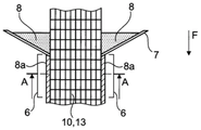
图2示出用于涂覆外侧的装置的细节的示意图;Figure 2 shows a schematic diagram of a detail of the device for coating the outside;
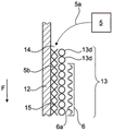
图3示出在相互结合过程中穿过硅氧烷软管和外部织物的纵向截面的细节示意图;Figure 3 shows a detailed schematic view of a longitudinal section through the silicone hose and the outer fabric during mutual bonding;
图4示出了沿图2的剖面线A-A的横截面;Figure 4 shows a cross-section along the section line A-A of Figure 2;
图5示出了穿过布置成扁平状的连续半成品的横截面;Figure 5 shows a cross-section through a continuous semi-finished product arranged in a flat shape;
图6示出了穿过折叠的连续半成品的横截面;Figure 6 shows a cross-section through a folded continuous semi-finished product;
图7示出了卷起的连续半成品的侧视图。Figure 7 shows a side view of the rolled continuous semi-finished product.
原则上,在附图中,相同的部件具有相同的附图标记。In principle, identical components have the same reference numerals in the figures.
具体实施方式detailed description
图1示出用于生产连续半成品10的设备1的示意图。在示意性所示的挤出装置2内,硅氧烷软管12以本身已知的方式由硅氧烷制成,该硅氧烷通过入口4a、4b从硅氧烷储存容器4供应。此时,硅氧烷软管12通过注入空气膨胀,然后膨胀的软管被硫化。如果硅氧烷软管12在其生产过程中要有一个孔,这将防止膨胀并且软管会塌陷。因此,在生产过程中,例如可以使用布置的传感器容易地检查硅氧烷软管是否至多具有泄漏点,和/或可以确保硅氧烷软管是流体密封的。因此,该生产方法确保了硅氧烷软管12的壁没有任何渗透点。如图1所示,内部导体11被另外地供应到挤出装置2,使得所述内部导体沿着所生产的硅氧烷软管12的内部空间延伸。内部导体11例如是用于将流体供应到硅氧烷软管12的内部空间中的编织软管。然而,内部导体11例如也可以是电导体,或者另外可以例如包括传感器,其中可以将其测量数据通过电导体返回给控制装置。硅氧烷软管12在输送方向F上以速度V1输送。FIG. 1 shows a schematic illustration of a plant 1 for producing a continuous
用示意性所示的输送装置9将硅氧烷软管12和位于其中的内部导体11供应到示意性示出的圆形编织3。圆形编织3以本身已知的方式将多个供应的经线13c与至少一个纬线13d交织,因此形成了管状的外部织物,该管状的外部织物形成了连续纤维软管13。连续纤维软管13在圆周方向上完全包围硅氧烷软管12,从而包括内部导体11、硅氧烷软管12和连续纤维软管13的管状的连续半成品10在输送方向F上以输送速度V2离开圆形编织3。The
如图2所示,随后将位于浸槽7中的涂层材料8施加到连续纤维软管13的外侧,并且完全包围连续纤维软管13的外侧。最初为液体的涂层材料8在此结合至连续纤维软管13的纤维,随后硬化以形成表面涂层8a,如此选择涂层材料8,使得其在硬化之后仍然保持弹性和柔性。硅氧烷优选用作涂层材料8。连续纤维软管13和/或管状的连续半成品10仅在图2中示意性地示出,为了更好说明,表面涂层8a被示出为比实际厚度大得多。As shown in FIG. 2 , the
图3示意性示出穿过硅氧烷软管12和连续纤维软管13的纵截面,所述硅氧烷软管和所述连续纤维软管位于圆形编织3中,最上面的纬线13d代表由圆形编织3引入的最新的纬线13d。连续纤维软管13的外径基本上由漏斗状的圆形编织3的边缘3a处的内径决定。在该边缘3a的区域中,如图1所示,将硅氧烷软管12插入在边缘3a的区域中获得的连续纤维软管13中。在此过程中,如图3所示,在连续纤维软管13与硅氧烷软管12之间形成间隙14。在特别有利的构造中,硅氧烷软管12至少在边缘3a的区域中张开,以便使间隙14可预测地保持宽度。从第二储存容器5开始,优选为硅氧烷的基质材料通过进料管线5a以在整个圆周方向上分布的方式供应给间隙14,硅氧烷软管12和连续纤维软管13在输送方向F上输送,并且在此过程中被供应到具有红外加热器6a的交联装置6。在此过程中,结合剂5b(其粘合至硅氧烷软管12的外表面和连续纤维软管13的内表面)和/或所供应的基质材料硬化,因此硅氧烷软管12和连续纤维软管13在硬化之后彼此结合,并且有利地在整个表面区域并且沿着整个圆周表面彼此结合或粘合。在有利的实施例中,连续纤维软管13的织物至少部分地并且有利地完全由聚酯纤维组成。交联装置6将该织物加热至例如120℃的温度,其结果是聚酯和/或由聚酯纤维制造的织物收缩,并且因此该阶段的织物从外侧接近硅氧烷软管,使得织物和硅氧烷软管至少在某些点相互接触,并通过基质材料相互粘合。图3未详细示出沿交联装置6在输送方向F上进行的这种间隙减小效果以及连续纤维软管13的直径的减小。Figure 3 schematically shows a longitudinal section through a
图1示意性示出张开装置16的实施例,张开装置16布置在硅氧烷软管12内部并且在圆周上分布有多个辊,该辊支承和/或可以支承在硅氧烷软管12的内部上,以便从内部张开硅氧烷软管12。张开装置16通过悬架16a连接至未示出的保持装置。有利的是,可以在硅氧烷软管12的延伸方向上改变和设置张开装置16的位置,优选以张开装置16位于边缘3a的区域中的方式,结果可以设置间隙14的宽度,并且优选地还可以设置在输送向F上延伸的间隙14的形式。FIG. 1 schematically shows an embodiment of a splay device 16 arranged inside a
图4示意性示出沿图2的剖面线A-A的完成的连续半成品10的横截面。硅氧烷软管12具有第一内部空腔12a。内部导体11以在第一内部空腔12a内延伸的方式布置,并具有第二内部空腔11a。连续纤维软管13和硅氧烷软管12通过结合层15彼此结合。连续纤维软管13还具有表面涂层8a。硅氧烷软管12具有内径D。在有利的构造中,取决于连续半成品10的使用领域,内径D在10-100厘米之间的范围内。在根据图4的示意性示出的横截面中,为了更清楚地示出,元件硅氧烷软管12、内部导体11、复合层15、连续纤维软管13和表面涂层8a被示出为比实际厚度大得多。FIG. 4 schematically shows a cross-section of the completed continuous
图1依次示出硅氧烷软管12的生产和连续半成品10的生产。在一种可能的方法中,所述硅氧烷软管和连续半成品可以立即连续生产。在有利的方法中,硅氧烷软管12在第一方法步骤中生产,此后硅氧烷软管12和布置在其中的内部导体11例如通过一起缠绕到储存介质上而暂时储存起来。在第二方法步骤中,临时储存的带有内部导体11的硅氧烷软管12被供应到圆形编织3,并且在此,硅氧烷软管12在圆周方向上被连续纤维软管13包覆并结合到其上。分成两个方法步骤的优点在于,借助于硅氧烷软管12与内部导体11的临时储存,可以毫无问题地补偿不同的生产速度和/或不同的输送速度V1、V2。但是,也可以以相同的输送速度操作第一方法步骤和第二方法步骤,使得由挤出机2生产的硅氧烷软管12可以直接返回到圆形编织3,并且以此方式可以连续生产硅氧烷软管12和整个连续半成品10。FIG. 1 shows the production of a
在生产之后,连续半成品10有利地被转化至扁平状态,如图5所示,使得几乎没有流体或没有流体还位于硅氧烷软管12的第一内部空腔12a和/或内部导体11的第二内部空腔11a中。在进一步有利的方法步骤中,连续半成品10至少折叠一次(如图6所示),随后卷成一卷(如图7所示)。井下换热器然后可以以如下方式简单地生产,将连续半成品切成所需的长度(例如50-500米之间),生产具有相应长度的井眼,并且已被切割成一定长度的连续半成品10的尖端10a设置有流体密封的封闭件,例如设置有所谓的探针脚。随后,包括探针脚和另外可选地可能的附加重量的尖端10a插入并下降到井眼中,直到已经被切割成一定长度的连续半成品10基本上下降到井眼中为止。在下降操作(优选完成)之后,加压流体供应至内部导体11,其结果是已被切割成一定长度的连续半成品特别是其硅氧烷软管12及其连续纤维软管13在井眼中张开。这样的布置已经可以用作井下换热器。然而,优选的是,在已被切割成一定长度的连续半成品在井眼中张开之后,内部导体11通过抽出而被移除,并引入优选为刚性的流体管线来代替内部导体11,它优选地相对于外部是绝热的,并且优选地基本上从井眼的入口延伸直到接近已被切割成一定长度的连续半成品10的流体密封的封闭件。井眼入口例如被理解为是指井眼进入地面的点。优选的是至少热交换装置和流体泵被布置在井眼入口前面的区域中。在井下换热器的运行过程中,在流体管线内部流动并在流体管线端部从流体管线流出的流体优选在流体密封的封闭件区域中通过流体管线供应,流体随后在基本上形成于流体管线与硅氧烷软管12之间的内部空间12a中再次流回到井眼入口。流体当然也可以沿相反方向流动,通过基本上在井眼入口的区域中将流体供应到内部空间12a,并且优选流到硅氧烷软管12内的流体密封的封闭件区域,并且在该区域中在流体管线的端部处进入流体管线,并且在流体管线内部基本上又被引导至井眼入口的区域。After production, the continuous
在有利构造中,连续半成品和/或井下换热器包括具有第一内部空间12a的硅氧烷软管12,包括在第一内部空间12a内部延伸的单独的内部导体11,并包括在外侧包覆硅氧烷软管12的连续纤维软管13,硅氧烷软管12和连续纤维软管13通过硬化的基质材料彼此结合。In an advantageous configuration, the continuous semi-finished product and/or the downhole heat exchanger comprises a
在有利构造中,连续半成品这样预制,使得它具有特定长度,连续半成品的要下降到井眼中的端部具有流体密封的封闭件,从而硅氧烷软管12形成流体密封端部,并且连续纤维软管13的端部优选具有覆盖硅氧烷软管12的流体密封端部的端面。优选的是提供多个具有不同长度的这种类型的连续半成品,以使可以根据相应的井眼深度从多个连续半成品中选择具有匹配长度的连续半成品。In an advantageous configuration, the continuous semi-finished product is prefabricated such that it has a specific length, the end of the continuous semi-finished product to be lowered into the wellbore has a fluid-tight closure, so that the
Claims (15)
Applications Claiming Priority (3)
| Application Number | Priority Date | Filing Date | Title |
|---|---|---|---|
| EP18186624.5 | 2018-07-31 | ||
| EP18186624.5A EP3603945A1 (en) | 2018-07-31 | 2018-07-31 | Endless semi finished product and method and device for producing an endless semi finished product, geothermal probe, borehole reinforcement and sanitation pipe |
| PCT/EP2019/070718 WO2020025720A1 (en) | 2018-07-31 | 2019-07-31 | Method and apparatus for producing an endless semi-finished product, endless semi-finished product, downhole heat exchanger, borehole reinforcement and restoration pipe |
Publications (2)
| Publication Number | Publication Date |
|---|---|
| CN112469552A CN112469552A (en) | 2021-03-09 |
| CN112469552B true CN112469552B (en) | 2022-12-30 |
Family
ID=63113371
Family Applications (1)
| Application Number | Title | Priority Date | Filing Date |
|---|---|---|---|
| CN201980049040.6A Active CN112469552B (en) | 2018-07-31 | 2019-07-31 | Method and apparatus for producing a continuous semifinished product, downhole heat exchanger, wellbore reinforcement and rehabilitating pipe |
Country Status (4)
| Country | Link |
|---|---|
| US (1) | US12311616B2 (en) |
| EP (2) | EP3603945A1 (en) |
| CN (1) | CN112469552B (en) |
| WO (1) | WO2020025720A1 (en) |
Families Citing this family (2)
| Publication number | Priority date | Publication date | Assignee | Title |
|---|---|---|---|---|
| EP4314669B1 (en) * | 2021-03-30 | 2026-02-25 | Senera Oy | Outer pipe and method for coaxial geothermal collector |
| CN115583056B (en) * | 2022-10-17 | 2026-02-03 | 公元管道(安徽)有限公司 | Heating structure of fiber composite pipe forming equipment |
Citations (6)
| Publication number | Priority date | Publication date | Assignee | Title |
|---|---|---|---|---|
| US5192476A (en) * | 1991-12-02 | 1993-03-09 | Teleflex Incorporated | Method for forming a conduit by pre-coating the conduit prior to braiding |
| CA2292822A1 (en) * | 1998-12-22 | 2000-06-22 | Philip Head | Sub sea and sub surface tubing and conductors |
| KR20100133682A (en) * | 2009-06-12 | 2010-12-22 | 정인선 | Resin Hose with Support on Endothelial |
| DE102012201262A1 (en) * | 2012-01-30 | 2013-08-01 | Burgmann Packings GmbH | Method for producing continuous semi-finished product used in manufacturing of fiber reinforced plastic profile, involves arranging long fibers continuously around flexible, tubular and inflatable hollow continuous core |
| DE102013205089A1 (en) * | 2013-03-22 | 2014-09-25 | Supertex Composites Gmbh | Method and production system for producing a fiber-reinforced structural component |
| CN104292402A (en) * | 2014-09-30 | 2015-01-21 | 青岛特瑞信电子科技有限公司 | High-temperature-resistant plastic hose |
Family Cites Families (4)
| Publication number | Priority date | Publication date | Assignee | Title |
|---|---|---|---|---|
| CH706507A1 (en) | 2012-05-14 | 2013-11-15 | Broder Ag | Coaxial borehole heat exchanger and method for assembling such a geothermal probe underground. |
| US20220186427A1 (en) * | 2014-08-22 | 2022-06-16 | San Fang Chemical Industry Co., Ltd. | Composite filament textile and composite filament artificial leather manufactured using the same |
| CH711385B1 (en) * | 2015-07-27 | 2019-06-14 | Bs2 Ag | Method and device for producing a line, line and geothermal probe. |
| JP6932346B2 (en) * | 2017-03-31 | 2021-09-08 | 三菱重工サーマルシステムズ株式会社 | Geothermal utilization system and geothermal utilization method |
-
2018
- 2018-07-31 EP EP18186624.5A patent/EP3603945A1/en not_active Withdrawn
-
2019
- 2019-07-31 CN CN201980049040.6A patent/CN112469552B/en active Active
- 2019-07-31 EP EP19752667.6A patent/EP3829855B1/en active Active
- 2019-07-31 US US17/255,697 patent/US12311616B2/en active Active
- 2019-07-31 WO PCT/EP2019/070718 patent/WO2020025720A1/en not_active Ceased
Patent Citations (6)
| Publication number | Priority date | Publication date | Assignee | Title |
|---|---|---|---|---|
| US5192476A (en) * | 1991-12-02 | 1993-03-09 | Teleflex Incorporated | Method for forming a conduit by pre-coating the conduit prior to braiding |
| CA2292822A1 (en) * | 1998-12-22 | 2000-06-22 | Philip Head | Sub sea and sub surface tubing and conductors |
| KR20100133682A (en) * | 2009-06-12 | 2010-12-22 | 정인선 | Resin Hose with Support on Endothelial |
| DE102012201262A1 (en) * | 2012-01-30 | 2013-08-01 | Burgmann Packings GmbH | Method for producing continuous semi-finished product used in manufacturing of fiber reinforced plastic profile, involves arranging long fibers continuously around flexible, tubular and inflatable hollow continuous core |
| DE102013205089A1 (en) * | 2013-03-22 | 2014-09-25 | Supertex Composites Gmbh | Method and production system for producing a fiber-reinforced structural component |
| CN104292402A (en) * | 2014-09-30 | 2015-01-21 | 青岛特瑞信电子科技有限公司 | High-temperature-resistant plastic hose |
Also Published As
| Publication number | Publication date |
|---|---|
| EP3829855B1 (en) | 2023-06-07 |
| EP3829855C0 (en) | 2023-06-07 |
| US20210283864A1 (en) | 2021-09-16 |
| EP3829855A1 (en) | 2021-06-09 |
| EP3603945A1 (en) | 2020-02-05 |
| US12311616B2 (en) | 2025-05-27 |
| WO2020025720A1 (en) | 2020-02-06 |
| CN112469552A (en) | 2021-03-09 |
Similar Documents
| Publication | Publication Date | Title |
|---|---|---|
| KR101126814B1 (en) | Cured in place liner with integral inner impermeable layer and continuous method of manufacture | |
| US5244624A (en) | Method of installing a new pipe inside an existing conduit by progressive rounding | |
| KR101154085B1 (en) | Cured in place liner with everted outer impermeable layer and method of manufacture | |
| KR960012319B1 (en) | Method for installing a substantially rigid thermoplastic pipe in an existing pipe line | |
| CN1886617B (en) | Installation and equipment of cured-in-place liners with internal impermeable layers | |
| CN106985427B (en) | Pipe structure | |
| US5368809A (en) | Method of installing a new pipe inside an existing conduit by progressive rounding | |
| CN112469552B (en) | Method and apparatus for producing a continuous semifinished product, downhole heat exchanger, wellbore reinforcement and rehabilitating pipe | |
| JP2009515746A (en) | In-situ curable liner reinforced longitudinally and reinforced coating | |
| KR101161455B1 (en) | Resin impregnation tower for cured in place liner | |
| CN103906886B (en) | The tubular equipment of continuous completion and corresponding method for arranging for hydrocarbon well | |
| JPH074855B2 (en) | Lining method | |
| JPH0341343B2 (en) | ||
| HK1095622B (en) | Resin impregnation tower for cured in place liner | |
| HK1095621B (en) | Cured in place liner with integral inner impermeable layer and continuous method of manufacture | |
| JPH11156940A (en) | Method for in-pipe lining and braid for in-pipe lining |
Legal Events
| Date | Code | Title | Description |
|---|---|---|---|
| PB01 | Publication | ||
| PB01 | Publication | ||
| SE01 | Entry into force of request for substantive examination | ||
| SE01 | Entry into force of request for substantive examination | ||
| GR01 | Patent grant | ||
| GR01 | Patent grant |