CN1124630C - Electromagnetic switch device having built-up casing - Google Patents
Electromagnetic switch device having built-up casing Download PDFInfo
- Publication number
- CN1124630C CN1124630C CN 99103479 CN99103479A CN1124630C CN 1124630 C CN1124630 C CN 1124630C CN 99103479 CN99103479 CN 99103479 CN 99103479 A CN99103479 A CN 99103479A CN 1124630 C CN1124630 C CN 1124630C
- Authority
- CN
- China
- Prior art keywords
- housing
- magnetic core
- armature
- described switching
- core housing
- Prior art date
- Legal status (The legal status is an assumption and is not a legal conclusion. Google has not performed a legal analysis and makes no representation as to the accuracy of the status listed.)
- Expired - Lifetime
Links
Images


Classifications
-
- H—ELECTRICITY
- H01—ELECTRIC ELEMENTS
- H01H—ELECTRIC SWITCHES; RELAYS; SELECTORS; EMERGENCY PROTECTIVE DEVICES
- H01H50/00—Details of electromagnetic relays
- H01H50/02—Bases; Casings; Covers
- H01H50/04—Mounting complete relay or separate parts of relay on a base or inside a case
- H01H50/041—Details concerning assembly of relays
- H01H50/045—Details particular to contactors
-
- H—ELECTRICITY
- H01—ELECTRIC ELEMENTS
- H01H—ELECTRIC SWITCHES; RELAYS; SELECTORS; EMERGENCY PROTECTIVE DEVICES
- H01H50/00—Details of electromagnetic relays
- H01H50/02—Bases; Casings; Covers
- H01H50/04—Mounting complete relay or separate parts of relay on a base or inside a case
- H01H50/041—Details concerning assembly of relays
- H01H50/042—Different parts are assembled by insertion without extra mounting facilities like screws, in an isolated mounting part, e.g. stack mounting on a coil-support
-
- H—ELECTRICITY
- H01—ELECTRIC ELEMENTS
- H01H—ELECTRIC SWITCHES; RELAYS; SELECTORS; EMERGENCY PROTECTIVE DEVICES
- H01H2300/00—Orthogonal indexing scheme relating to electric switches, relays, selectors or emergency protective devices covered by H01H
- H01H2300/042—Application rejection, i.e. preventing improper installation of parts
-
- H—ELECTRICITY
- H01—ELECTRIC ELEMENTS
- H01H—ELECTRIC SWITCHES; RELAYS; SELECTORS; EMERGENCY PROTECTIVE DEVICES
- H01H50/00—Details of electromagnetic relays
- H01H50/02—Bases; Casings; Covers
- H01H50/021—Bases; Casings; Covers structurally combining a relay and an electronic component, e.g. varistor, RC circuit
-
- H—ELECTRICITY
- H01—ELECTRIC ELEMENTS
- H01H—ELECTRIC SWITCHES; RELAYS; SELECTORS; EMERGENCY PROTECTIVE DEVICES
- H01H50/00—Details of electromagnetic relays
- H01H50/16—Magnetic circuit arrangements
- H01H50/18—Movable parts of magnetic circuits, e.g. armature
- H01H50/30—Mechanical arrangements for preventing or damping vibration or shock, e.g. by balancing of armature
- H01H50/305—Mechanical arrangements for preventing or damping vibration or shock, e.g. by balancing of armature damping vibration due to functional movement of armature
Abstract
The electromagnetic switch, especially a contactor has a contact space receiving the stationary and movable contacts and a drive space receiving a magnetic drive with a magnetic core, an electromagnetic coil and a movable magnetic armature, for operation of the movable contacts, defined by a multi-part switch housing. The drive space housing (100) has a magnetic core housing frame (10) and a magnetic armature housing frame (20) fitted together with container chamber opening upward and downward, with a base plate (30) secured to the open underside of the magnetic core housing frame.
Description
The present invention relates to an electromagentic switching apparatus, contactor particularly, has a contact cavities and an actuator chamber that is used for electromagnetic actuator device that is used for moving contact and fixed contact, electromagnetic actuator device includes magnetic core, coil and is used for the armature of operating contact, and they are contained in the housing of many parts composition.
Such as from DE4244606C2, known this electromagentic switching apparatus.Because in order as requested electromagentic switching apparatus to be made into the different structure size in the loading range making current, so what be worth pursuit is, as far as possible similarly make a structural series and be every kind of the least possible and simple as far as possible part of physical dimension use, in addition, in different physical dimensions, also use series of identical constitutional detail.In addition, what be worth to pursue is, can make electromagentic switching apparatus economically in automatic production line, and each single part is assembled into contactor in succession according to performance or once more preassembled parts is packed in the housing.
Task of the present invention is, the electromagentic switching apparatus of a structural series different structure size is with the least possible and simple part and many identical part manufacturings, and simple economy ground installation as far as possible simultaneously.Here, it is as much as possible little that manufacturing tolerance also should keep, and avoid the calibration operation that takes a lot of trouble.
According to the present invention, this task can be resolved when indicating the electromagentic switching apparatus of feature according to claim 1 adopting.
According to the present invention, the housing that includes actuator chamber partly is made up of two frame type housings that constituted a magnetic core housing and armature housing, had a containing cavity that opens wide up and down, and bottom that the magnetic core housing opens wide is sealed by means of a base plate that is placed in below the magnetic core housing.According to the present invention, housing is divided into magnetic core housing and armature housing.Two housing parts are screwed in together mutually with screw.The magnetic core housing bottom opens wide, and the base plate of the involved soft copy that the printed circuit board (PCB) form arranged sealing and covering.Adopt the present invention can reach the simple structure of the instrument of housing parts and manufacturing housing parts.The base plate of switching device can use as same parts on all physical dimensions of structural series.In a switching device, also can dismantle switching device in addition fully and just can change the printed circuit board (PCB) that has electronic component, because can change these printed circuit board (PCB)s from housing bottom by unclamping base plate.
From the feature that dependent claims is indicated, can obtain other favourable structures according to switching device of the present invention.
For fixed magnetic core, be that the magnetic core that two axles are housed has the shaft end that is constructed to bearing and can be inserted in the groove of constructing in the magnetic core housing in top insertion magnetic core housing according to another structure of magnetic core housing of the present invention.In addition, according to the present invention, the corresponding bearing-surface with the consistent moulding of magnetic core housing groove has been constructed in armature housing the inside, like this, when the magnetic core housing was connected with screw mutually with the armature housing, corresponding bearing-surface inserted in the groove that is engaged to the magnetic core housing and is pressed onto on the bearing of magnetic core.Advantageously, the bearing of magnetic core is wrapped between two flexible vibration damper plates, these two vibration damper plates be pine lay, like this, they have prestressing force when connecting magnetic core housing and armature housing with screw.
The containing groove of magnetic core bearing preferably is arranged to basin shape, is located in the magnetic core housing interior angle part, and has a supporting slot that be open upwards, that be used for ccontaining core axis in its side towards magnetic core.
Another favourable structure can obtain simply installing magnetic core housing and the armature housing with the supporting-line circle body.Advise according to the present invention for this reason, the magnetic core housing inside have be used to lay coil case, at magnetic core one side support plate up, the armature housing that is placed on above the magnetic core housing has inside been constructed as coil case like this by putting the protruding part of part, coil case is fixed between magnetic core housing support plate and the armature housing protruding part with enough gaps, therefore, coil case itself load that can not be under pressure.By the spacing between support plate and protruding part predetermined when connecting armature housing and magnetic core housing with screw, can regulate the gap of leaving and keep less, can guarantee that like this coil case itself can pressurized, and make because the wearing and tearing minimum of the bearing-surface that the coil case motion causes.In addition, adopt this mode not need the coil case fixture that adds.
Advise that in according to another shell structure of the present invention at least one guiding parts can be fixed on the inwall of armature housing and/or magnetic core housing.According to guiding parts of the present invention at the magnetic core shell complete and armature housing assembling and with the screw connection status under can constitute the joint of the division between magnetic core housing and the armature housing with overlapping.Guiding parts has formed a guiding receiving member that is used for other movable members in the part in it extends to the armature housing simultaneously, such as the electric bridge with armature contact.According to guiding parts of the present invention is parts separately, and they preferably can be installed on the armature housing by insertion by means of a dovetail type connector.Can use by independent structure guiding parts to have good sliding properties and the anti abrasive material that is suitable for leading, on the contrary, housing can use the material with suitable strength characteristic.Guiding parts is identical parts for a structural series different structure size switches device.
The favourable structure of switching device is to have a guiding parts to be installed on the relative mutually both sides of armature housing by means of a dovetail type connector respectively.In addition, for the guide frame form, suggestion has in the middle of top at one mutually relative of the inside, both sides structure of armature housing and is bag shape groove targeting part, that open wide and the dovetail slide bearing that stretches from the top down downwards, and guiding parts can insert in this dovetail slide bearing with the swallow-tail form engaging groove that constitutes at guiding parts from following.Guiding parts can constitute like this, and under the immigration state, guiding parts has enough projections below the armature housing, is used to mesh be inserted into inside the magnetic core housing that is used for guider.
In addition, electromagentic switching apparatus needs to connect outward, connects and suitable being connected of coupling of situation about existing with the scene respectively as coil.Particularly these connections also will be complementary with the switching device of different structure size.Connect in order to use unified structure parts to be used for these, suggestion adopts link block to be used for the outer connection of switching device.In according to another switchgear configurations of the present invention, advise, link block is set, the magnetic core housing has the slot with this two sides extends parallel in the above by the angular position in mutually relative both sides, be used for ccontaining link block, this groove has such jack inside, and the link block that is configured with T shape or is similar to insertion sheet such shape, that can snap in engagement is inserted in these slots.
Link block makes mutual identical construction, particularly is provided with three link blocks and so-called the 4th an empty module, and this sky module is identical with link block in shape, by this, can reach the connection of simple structure.For fixedly connected module, advise according to the present invention, the armature housing has four guiding protruding parts altogether on two mutual opposite external side, be used for when the armature housing is connected with the magnetic core housing, accurately importing to ordinatedly between four link blocks or empty module that are plugged on the magnetic core housing, prevented that by this link block or empty module from dropping out.
On the guiding protruding part that link block is fixed to the armature housing, also the side stay hook can be set, when inserting the armature housing, link block enters in the side stay hook.For fixedly connected module, do not need loose fitting, as screw or similar articles.The assembling principle is applicable to all physical dimensions, and these link blocks can be used for various physical dimension together in an identical manner with corresponding device thereof.
In addition, predetermined according to the present invention, to connect mutually and the housing parts that will accurately cooperate assembling mutually, as base plate and printed circuit board (PCB), dispose counterpart, as projection and hole; Magnetic core housing and armature housing have the counterpart of a protruding part-groove-fit form at least for accurately assembling ordinatedly in the junction of dividing.
According to of the present invention, include housing actuator chamber, that form by magnetic core housing and armature housing at last by armature is become complete from top insertion armature housing.Here, this armature preferably is fixed on the ccontaining housing downside of armature cover, and like this, the ccontaining housing of armature cover can insert the armature housing in desired position and cooperate in the support slot accordingly.
According to the present invention, the hold-down screw that connects armature housing and magnetic core housing places the recessed deep gouge in the side flange of armature housing with its head.This groove also can be used for the carriage of ccontaining electric motor protecting relay.Its advantage is, do not need for carriage is fixed to chuck to be set in addition on the housing, also need perforate on housing.
Describe the present invention by means of accompanying drawing in detail with embodiment below.Accompanying drawing shows:
Fig. 1: according to the housing parts perspective view that includes actuator chamber of the present invention;
Fig. 2: the parts explosion that constitutes the electromagentic switching apparatus actuator chamber;
Fig. 3: magnetic core housing exploded view with magnetic core;
Fig. 4: have the magnetic core housing of guiding parts and the exploded view of armature housing;
Fig. 5: have the magnetic core housing of link block and the exploded view of armature housing;
Fig. 6: have the magnetic core housing of insertion coil case and the vertical view of armature housing;
Fig. 7: damper element;
Fig. 8: the bearing that is used for magnetic core;
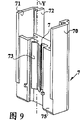
Fig. 9: according to the guiding parts of Fig. 4;
Figure 10: the exploded view of armature housing and coil case;
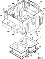
Figure 11: the exploded view of base plate and printed circuit board (PCB).
The present invention research according to Fig. 1, include the structure of the housing parts 100 of actuator chamber.Housing 100 is divided into magnetic core housing 10 and armature housing 20.Two housings connect with screw mutually.The bottom of magnetic core housing is opened wide, and a printed circuit board (PCB) is presented to the inside, covers to 30 sealings of external application base plate.Link block 4 and an empty module 4a are close to armature housing 20 in the side and are placed on the magnetic core housing 10.
Fig. 2 shows according to electromagentic switching apparatus actuator chamber of the present invention structure partly with the form of exploded view.Magnetic core housing 10 is frame-types, and a containing cavity A1 who opens wide is up and down arranged.P1 is from 10 li of following insertion magnetic core housings in the direction of arrows for printed circuit board (PCB) 3, and the base plate 30 that is used in the placement of arrow P 1 direction on downward direction outwards covers.See Fig. 1 and Figure 11, this base plate passes screw hole 301 with the screw that does not illustrate and is fixed on the magnetic core housing 10.Printed circuit board (PCB) 3 is seen Figure 11, has a bathtub construction with plastic production, and the circuit board that includes soft copy is cast in the bathtub construction.On base plate 30, constructed supporting convex spare 302, base plate has been packed in the corresponding mating holes 3d of printed circuit board (PCB) 3 with it.Make 10 times face closures of magnetic core housing by insert printed circuit board (PCB) 3 and base plate 30 according to Fig. 2.Magnetic core is inserted 10 li of magnetic core housings from top P2 in the direction of arrows; Magnetic core 2 is seen Fig. 3, has two axles 221,222; Plastic seating 5 is seen Fig. 8, is inserted on their four ends.Each plastic seating 5 all is stamped one such as the vibration damper plate 6 made by rubber with following in the above, the vibrations that they can buffer electromagnet.The longitudinal axis of magnetic core 2 is indicated with X, in this this axis horizontal expansion.Magnetic core housing 10 is seen Fig. 2, as the framework that opens wide two mutual relative hollow sidewall 103,104 is arranged, and they are to open wide downwards, according to the electronic component of the printed circuit board (PCB) of Fig. 2 in the direction of arrows P1 can pack in it.Two of the magnetic core housing vertical side 101,102 opposing sidewalls 103,104 that connect hollow sidewall 103,104 are moved backward, have constituted angle part with fixing possibility so here respectively, as slot 114 or hole 114a.
In the inside of sidewall 102,103, in angular region, constructed basin connected in star 106, they upwards open wide, and are used for the bearing 5,6 of ccontaining magnetic core.These grooves at it towards having the supporting slot 107 that is open upwards, be used to insert core axis 221,222 in the containing cavity A1 and on the side of magnetic core 2.
In addition,, be formed separately a fixedly projection 115 being used to support between the containing groove 106 of magnetic core 2, be used for laying helical spring, also seen Fig. 2 as the compression spring between magnetic core housing and the armature-cover-receiving member 90 in sidewall 101,102 inboards.At pockets 106 be used to compress between the fixedly projection 115 of spring 7a, be provided with the containing cavity 108 that is used for the high electronic component that can insert in connection with the sidewall 101,102 of magnetic core housing 10 from below in the inboard.These ccontaining parts 108 can be closed in the above.Go out as shown in FIG. 2, magnetic core 2 inserts 10 li of magnetic core housings, and coil case 8 is put into magnetic core housing 10 and is placed to above the support plate 111,112 then.Armature housing 20 with containing cavity A2 is placed in above the magnetic core housing 10 and in the side to be screwed on screw.In Figure 10, at length show armature housing 20.Armature housing 20 also is configured to frame shape, opens wide up and down, and the longitudinal axis X with respect to magnetic core 2 is symmetrical equally.On two mutual relative sidewalls 203,204, constructed side flange 206 outside with hole 207, be used for an armature housing to be fixed on the magnetic core housing.On two relative mutually in addition sidewalls 201,202, the reinforcing protruding part 211 that has been shaped outside, they have the stay hook 213 that stretches out downwards at upside on the side, and the cooperation projection 218 that has been shaped below.Sidewall 201,202 and reinforcing protruding part 211 have storage tank 208 or 212 respectively in the centre, be used to insert and lead have the armature 9 of the ccontaining housing 90 of armature cover, see Fig. 2.At the upside of armature housing 20, be provided with the mating groove 219 that is used to connect housing equally for 203,204 li at sidewall, stay hook 205 is equally also arranged.For the static line circle body, armature housing 20 has been constructed the protruding part 209 that stretches out from sidewall 203,204 inside, and it has by putting face 209a, and the edge of coil case 8 rests on this by putting on the face.
Fig. 6 has illustrated with schematic diagram, and is how fixing by armature housing 20 being placed to the coil case 8 that is inserted on the magnetic core housing 10 in the magnetic core housing 10, on the unshowned magnet with protruding part 208.Coil case 8 is fixed on enough gaps between a plurality of protruding parts 209 and magnetic core housing support plate 111,112 of armature housing 20, like this, at housing parts with under the screw connection status, the coil case load that can not be under pressure itself.
In Figure 10, show coil case 8 equally.Coil case is made with the location by assembling by two identical coils and is had connecting pin 83 on one or two relative narrower one side.Side in the coil edge extent has a unlimited winding wire guide channel 84 to lead to connecting pin 83.
In addition, armature housing 20 is used for ccontaining guiding parts 7, sees Fig. 2 and 4.For this reason, see Figure 10, armature housing 20 has been constructed a slotted recess 214 by 217 of downsides inside, guide 215 in the middle of this groove has.In the middle of in groove, in longitudinal extension, constructed a dovetail slideway 216.Guiding parts 7 is seen Fig. 9, has lateral connecting board 71,70, and they protrude upward above mid portion 74 and have constituted ccontaining part 72.On middleware a side longitudinally axis Y constructed dovetail type engaging groove 73, guiding parts 7 can push from below in the dovetail slideway 216 in armature housing 20 grooves 214 by this dovetail type mating groove.On the side with swallow-tail form mating groove 73 according to the guiding parts 7 of Fig. 9, lateral connecting board 71 protrudes some forward and has formed the mating part that can extend jointly with middleware on the whole length of guiding parts.
Can see that in Fig. 4 how guiding parts 7 is inserted into 214 li of grooves in the armature housing 20 from below, and, by lateral connecting board 71,70 to the inside, promptly additionally constituted the ccontaining part 72 of bathtub construction towards containing cavity A2.In addition, restricted as the insertion of guiding parts 7, stretch out from sidewall 101,102 the insides of magnetic core housing 10 and to have constructed two support plates 117.Guiding parts is used for stretching into from above the guiding of the movable members in the armature housing.
See Fig. 2 and Fig. 5, link block 4 is inserted into 110 li of the plug joints that are positioned on the magnetic core housing upper side.And then, armature housing 20 P2 in the direction of arrows is inserted on the magnetic core housing 10, and here, the armature housing stretches between two link blocks 4 respectively or between link block and the empty module 4a and it is put in place with reinforcing protruding part 211.The guide 213 of armature housing 20 produces fixations, and this guide is inserted in the respective grooves on adjacent link block 4 one sides.After the armature housing being placed on the magnetic core housing that link block is housed and after magnetic core, coil case, guiding parts and compression spring being packed in advance, with screw S armature housing 20 is linked together with magnetic core housing 10, see Fig. 6.Then, proceeded the installation of final assembling and contact cavities and other switchgear components according to the housing parts that includes actuator chamber 100 of the electromagentic switching apparatus of Fig. 1.Assembled and be tightened in together the armature housing and magnetic core housing, be placed superincumbent, have four armature housings that place the bearing-surface 210 of bight inner underside, be pressed onto be positioned at 106 li of magnetic core housing groove and magnetic core plastic supporting that cover with damper element on and it is fixed, see Figure 10.Here, vibration damper plate 6 is compacted, and they have prestressing force under the state of packing into like this.
Claims (16)
1. electromagentic switching apparatus, contactor particularly, has a contact cavities and an actuator chamber that is used for electromagnetic actuator device that is used for moving contact and fixed contact, this electromagnetic actuator device includes magnetic core (2), coil and the armature (9) that is used for operating contact, they are contained in the housing of many parts composition, it is characterized in that, the housing (100) that includes actuator chamber is by having constituted a magnetic core housing (10) and an armature housing (20), has the containing cavity (A1 that opens wide up and down, A2) two frame type housings are partly formed, and the bottom that magnetic core housing (10) opens wide is sealed by means of a base plate (30) that is placed in magnetic core housing bottom surface.
2. according to the described switching device of claim 1, it is characterized in that, be provided with a groove (106) that is configured in magnetic core housing (10) the inside, two axles (221 are housed, 222) magnetic core (2) is inserted in the groove (106) from top insertion magnetic core housing (10) lining and with the axle head that is configured to bearing (5), has corresponding bearing-surface (210) in the armature housing (20) with the consistent moulding of groove of magnetic core housing (10), like this, when magnetic core housing (10) was connected with screw mutually with armature housing (20), corresponding bearing-surface (210) mating reaction of armature housing (20) was to groove (106) lining of magnetic core housing (10) and be pressed onto on the bearing (5) of magnetic core (2).
3. according to claim 1 or 2 described switching devices, it is characterized in that, the support plate (111 that is used to lay coil case has been constructed in the inside at magnetic core housing (10) in magnetic core one side, 112), be placed in the armature housing (20) above the magnetic core housing (10) and constructed as the protruding part (209) of coil case (8) by putting part, coil case (8) is fixed on a plurality of support plates (111 of magnetic core housing (10) with enough gaps, 112) and between armature housing (20) protruding part (209), like this, coil case (8) itself load that can not be under pressure.
4. according to the described switching device of claim 2, it is characterized in that the bearing (5) of magnetic core (2) is enclosed between two elastic shock attenuation plates (6), like this, when having interconnected magnetic core housing (10) and armature housing (20) with screw, they have prestressing force.
5. according to the described switching device of claim 4, it is characterized in that the bearing (5) of magnetic core (2) is made of plastics, vibration damper plate (6) is made by rubber.
6. according to the described switching device of claim 1, it is characterized in that printed circuit board (PCB) (3) has a bathtub construction, it has a circuit board that is cast in the plastics the inside.
7. according to the described switching device of claim 1, it is characterized in that at least one guiding parts (7) can be fixed on the inwall of armature housing (20) and/or magnetic core housing (10).
8. according to the described switching device of claim 7, it is characterized in that, guiding parts (7) constructed on its top that is arranged in armature housing (10) lining one be used for movable part, as the guiding receiving member (72) of an electric bridge.
9. according to claim 6 or 7 described switching devices, it is characterized in that having a guiding parts (7) to be installed on the relative mutually side of armature housing (20) or magnetic core housing (10) respectively by means of a dovetail type connector.
10. according to the described switching device of one of claim 6 to 8, it is characterized in that, constructed a dovetail slide bearing (216) that has bag shape groove (214) the middle targeting part (215) in top, that open wide downwards and stretch from the top down in the mutual relative the inside, both sides of armature housing (20), guiding parts (7) is from inserting in this dovetail slide bearing below by the swallow-tail form mating groove (73) of constructing at guiding parts (7).
11. according to the described switching device of claim 1, it is characterized in that, be provided with link block (4,4a), be used for ccontaining link block (4, magnetic core housing (10) 4a) has slot (110) with these sidepiece extends parallel in the above at two mutual relative sidepieces by the angle part, these grooves have such patchhole inside, make by T shape or be similar to such shape, can be engaged the link block that the insertion sheet (41) that blocks constitutes and can be inserted in these slots.
12. according to the described switching device of claim 11, it is characterized in that, armature housing (20) is at two mutual opposite external side faces (201, two module chucks (211) are arranged respectively 202), be used for accurately importing to link block (4 on two insertion magnetic core housings (10) when being connected ordinatedly at armature housing (20) and magnetic core housing (10), 4a) or between the empty module, prevented that by this link block or empty module from dropping out.
13., it is characterized in that the lateral surface (201,202) of armature housing (20) has the side guiding protruding part in the link block of being engaged to according to the described switching device of claim 12.
14., it is characterized in that magnetic core housing (10) and armature housing (20) in the junction of dividing, have the cooperation of a projection-groove-fit form for accurately assembling ordinatedly at least according to claim 1 or 2 described switching devices.
15. according to claim 1 or 2 described switching devices, it is characterized in that, be fixed on containing cavity (A2) lining that armature (9) on the ccontaining housing of armature cover (90) can be inserted into armature housing (20) from above.
16. according to the described switching device of claim 2, it is characterized in that, the groove (106) of ccontaining magnetic core (2) bearing (5) on magnetic core housing (10) is configured to basin shape, and has the supporting slot (107) of that be open upwards, the axle that is used for inserting magnetic core (2) in the side towards magnetic core.
Applications Claiming Priority (2)
| Application Number | Priority Date | Filing Date | Title |
|---|---|---|---|
| DE1998114432 DE19814432C1 (en) | 1998-03-31 | 1998-03-31 | Electromagnetic switching device with a multi-part housing |
| DE19814432.6 | 1998-03-31 |
Publications (2)
| Publication Number | Publication Date |
|---|---|
| CN1230759A CN1230759A (en) | 1999-10-06 |
| CN1124630C true CN1124630C (en) | 2003-10-15 |
Family
ID=7863135
Family Applications (1)
| Application Number | Title | Priority Date | Filing Date |
|---|---|---|---|
| CN 99103479 Expired - Lifetime CN1124630C (en) | 1998-03-31 | 1999-03-31 | Electromagnetic switch device having built-up casing |
Country Status (4)
| Country | Link |
|---|---|
| EP (1) | EP0948016B1 (en) |
| CN (1) | CN1124630C (en) |
| DE (1) | DE19814432C1 (en) |
| HK (1) | HK1022209A1 (en) |
Families Citing this family (8)
| Publication number | Priority date | Publication date | Assignee | Title |
|---|---|---|---|---|
| JP2004047141A (en) * | 2002-07-09 | 2004-02-12 | Fuji Electric Holdings Co Ltd | Electromagnetic contactor |
| JP4321256B2 (en) | 2003-12-22 | 2009-08-26 | オムロン株式会社 | Electromagnetic relay |
| DE102004009650B3 (en) | 2004-02-27 | 2005-07-07 | Moeller Gmbh | Protection switch with upper part of main housing having stepped-back edge fitted with termination module with control clamps connected to magnetic coil of electromagnetic drive in housing lower part |
| KR100990267B1 (en) * | 2008-12-03 | 2010-10-26 | 엘에스산전 주식회사 | Electromagnetic contactor with abrasion preventing means |
| CN103811229B (en) * | 2014-03-12 | 2016-01-13 | 瞿建喜 | A kind of one pole Qian Installed formula electromagnetic switch |
| CN110476216B (en) * | 2017-03-27 | 2022-07-08 | 日立金属株式会社 | Coil component |
| DE102021106091A1 (en) * | 2021-03-12 | 2022-09-15 | Tdk Electronics Ag | housing arrangement |
| DE102021106112A1 (en) * | 2021-03-12 | 2022-09-15 | Tdk Electronics Ag | Enclosure for electromechanical component |
Family Cites Families (7)
| Publication number | Priority date | Publication date | Assignee | Title |
|---|---|---|---|---|
| DE1138141B (en) * | 1958-07-29 | 1962-10-18 | Weyer & Zander K G | Form-fitting elastic connection between the magnet armature and the switching bridge of an air rifle |
| US3060355A (en) * | 1960-05-20 | 1962-10-23 | Westinghouse Electric Corp | Relay magnet suspension |
| DE1590884A1 (en) * | 1966-03-03 | 1970-12-17 | Schaltelektronik Oppach Veb K | Electrical contactor consisting of several assemblies |
| US3835425A (en) * | 1973-11-01 | 1974-09-10 | Square D Co | Electromagnetic relay with reversible switch modules |
| US4506243A (en) * | 1981-05-28 | 1985-03-19 | Mitsubishi Denki Kabushiki Kaisha | Electromagnetic contactor |
| DE4244606C2 (en) * | 1992-12-31 | 1995-08-31 | Kloeckner Moeller Gmbh | Electromagnetic switching device |
| DE4322648C1 (en) * | 1993-07-07 | 1994-08-18 | Siemens Ag | Apparatus having a coil with four legs |
-
1998
- 1998-03-31 DE DE1998114432 patent/DE19814432C1/en not_active Expired - Lifetime
-
1999
- 1999-03-16 EP EP19990105335 patent/EP0948016B1/en not_active Expired - Lifetime
- 1999-03-31 CN CN 99103479 patent/CN1124630C/en not_active Expired - Lifetime
-
2000
- 2000-02-26 HK HK00101181A patent/HK1022209A1/en not_active IP Right Cessation
Also Published As
| Publication number | Publication date |
|---|---|
| HK1022209A1 (en) | 2000-07-28 |
| EP0948016A2 (en) | 1999-10-06 |
| EP0948016B1 (en) | 2005-08-31 |
| CN1230759A (en) | 1999-10-06 |
| DE19814432C1 (en) | 1999-12-23 |
| EP0948016A3 (en) | 2000-10-11 |
Similar Documents
| Publication | Publication Date | Title |
|---|---|---|
| CN1124630C (en) | Electromagnetic switch device having built-up casing | |
| CN100337056C (en) | Electromagnetic valve with terminal box | |
| CN103258689B (en) | Contact arrangement | |
| CN101755368B (en) | Waterproof connector, mounting structure for waterproof connector, and mounting method for waterproof connector | |
| US8232688B2 (en) | Voice coil motor type focusing actuator | |
| CA2160054C (en) | Waterproof casing structure for electronic equipment | |
| US5674090A (en) | Casing for receiving electrical connection box | |
| US20100139428A1 (en) | Electromotive Linear Drive | |
| CN1977442B (en) | Housing part for a drive unit and method and tool for the production thereof | |
| CN101364686B (en) | Rubber stopper for waterproof connector and waterproof connector | |
| JPWO2012164730A1 (en) | Battery case and battery pack including the same | |
| US7545248B2 (en) | Structure of magnet switch ensuring stability of installation of seal | |
| CN1204170A (en) | Floatable connector | |
| JP2003158846A (en) | Enclosed compressor | |
| JP5037740B1 (en) | Battery case and battery pack including the same | |
| CN1129931C (en) | Electromagnetic relay | |
| EP1049127B1 (en) | Electromagnetic relay, apparatus and method for making it | |
| KR100519868B1 (en) | Electric apparatus | |
| EP3537547A1 (en) | Electric plug with elastic press-on elements | |
| CN1117210A (en) | Integral seal and strain relief member for a connector | |
| CN1783365A (en) | Bistable two-way electromagnet | |
| CN207433428U (en) | High-voltage relay distributor disk | |
| CN207399670U (en) | High-voltage relay distributor disk | |
| KR20120039040A (en) | Plug connection of a mechatronic assembly of a motor vehicle | |
| CN205264913U (en) | Wall socket |
Legal Events
| Date | Code | Title | Description |
|---|---|---|---|
| C06 | Publication | ||
| PB01 | Publication | ||
| C10 | Entry into substantive examination | ||
| SE01 | Entry into force of request for substantive examination | ||
| C14 | Grant of patent or utility model | ||
| GR01 | Patent grant | ||
| CX01 | Expiry of patent term | ||
| CX01 | Expiry of patent term |
Granted publication date: 20031015 |