EP3537547A1 - Electric plug with elastic press-on elements - Google Patents
Electric plug with elastic press-on elements Download PDFInfo
- Publication number
- EP3537547A1 EP3537547A1 EP19160524.5A EP19160524A EP3537547A1 EP 3537547 A1 EP3537547 A1 EP 3537547A1 EP 19160524 A EP19160524 A EP 19160524A EP 3537547 A1 EP3537547 A1 EP 3537547A1
- Authority
- EP
- European Patent Office
- Prior art keywords
- press
- housing
- inner housing
- outer housing
- electric plug
- Prior art date
- Legal status (The legal status is an assumption and is not a legal conclusion. Google has not performed a legal analysis and makes no representation as to the accuracy of the status listed.)
- Granted
Links
- 230000000295 complement effect Effects 0.000 claims description 9
- 238000004519 manufacturing process Methods 0.000 description 6
- 238000003825 pressing Methods 0.000 description 6
- 238000001746 injection moulding Methods 0.000 description 4
- 238000012423 maintenance Methods 0.000 description 3
- 239000000463 material Substances 0.000 description 3
- 238000011161 development Methods 0.000 description 2
- 230000018109 developmental process Effects 0.000 description 2
- 230000013011 mating Effects 0.000 description 2
- 238000000034 method Methods 0.000 description 2
- 238000010146 3D printing Methods 0.000 description 1
- 238000010521 absorption reaction Methods 0.000 description 1
- 238000010276 construction Methods 0.000 description 1
- 230000008878 coupling Effects 0.000 description 1
- 238000010168 coupling process Methods 0.000 description 1
- 238000005859 coupling reaction Methods 0.000 description 1
- 230000007547 defect Effects 0.000 description 1
- 238000007598 dipping method Methods 0.000 description 1
- 239000002184 metal Substances 0.000 description 1
- 230000001681 protective effect Effects 0.000 description 1
- 239000002994 raw material Substances 0.000 description 1
- 239000000243 solution Substances 0.000 description 1
- 230000006641 stabilisation Effects 0.000 description 1
Images
Classifications
-
- H—ELECTRICITY
- H01—ELECTRIC ELEMENTS
- H01R—ELECTRICALLY-CONDUCTIVE CONNECTIONS; STRUCTURAL ASSOCIATIONS OF A PLURALITY OF MUTUALLY-INSULATED ELECTRICAL CONNECTING ELEMENTS; COUPLING DEVICES; CURRENT COLLECTORS
- H01R13/00—Details of coupling devices of the kinds covered by groups H01R12/70 or H01R24/00 - H01R33/00
- H01R13/46—Bases; Cases
- H01R13/533—Bases, cases made for use in extreme conditions, e.g. high temperature, radiation, vibration, corrosive environment, pressure
-
- H—ELECTRICITY
- H01—ELECTRIC ELEMENTS
- H01R—ELECTRICALLY-CONDUCTIVE CONNECTIONS; STRUCTURAL ASSOCIATIONS OF A PLURALITY OF MUTUALLY-INSULATED ELECTRICAL CONNECTING ELEMENTS; COUPLING DEVICES; CURRENT COLLECTORS
- H01R13/00—Details of coupling devices of the kinds covered by groups H01R12/70 or H01R24/00 - H01R33/00
- H01R13/46—Bases; Cases
- H01R13/516—Means for holding or embracing insulating body, e.g. casing, hoods
-
- H—ELECTRICITY
- H01—ELECTRIC ELEMENTS
- H01R—ELECTRICALLY-CONDUCTIVE CONNECTIONS; STRUCTURAL ASSOCIATIONS OF A PLURALITY OF MUTUALLY-INSULATED ELECTRICAL CONNECTING ELEMENTS; COUPLING DEVICES; CURRENT COLLECTORS
- H01R13/00—Details of coupling devices of the kinds covered by groups H01R12/70 or H01R24/00 - H01R33/00
- H01R13/46—Bases; Cases
- H01R13/502—Bases; Cases composed of different pieces
- H01R13/506—Bases; Cases composed of different pieces assembled by snap action of the parts
-
- H—ELECTRICITY
- H01—ELECTRIC ELEMENTS
- H01R—ELECTRICALLY-CONDUCTIVE CONNECTIONS; STRUCTURAL ASSOCIATIONS OF A PLURALITY OF MUTUALLY-INSULATED ELECTRICAL CONNECTING ELEMENTS; COUPLING DEVICES; CURRENT COLLECTORS
- H01R13/00—Details of coupling devices of the kinds covered by groups H01R12/70 or H01R24/00 - H01R33/00
- H01R13/46—Bases; Cases
- H01R13/502—Bases; Cases composed of different pieces
- H01R13/5025—Bases; Cases composed of different pieces one or more pieces being of resilient material
-
- H—ELECTRICITY
- H01—ELECTRIC ELEMENTS
- H01R—ELECTRICALLY-CONDUCTIVE CONNECTIONS; STRUCTURAL ASSOCIATIONS OF A PLURALITY OF MUTUALLY-INSULATED ELECTRICAL CONNECTING ELEMENTS; COUPLING DEVICES; CURRENT COLLECTORS
- H01R13/00—Details of coupling devices of the kinds covered by groups H01R12/70 or H01R24/00 - H01R33/00
- H01R13/46—Bases; Cases
- H01R13/502—Bases; Cases composed of different pieces
- H01R13/504—Bases; Cases composed of different pieces different pieces being moulded, cemented, welded, e.g. ultrasonic, or swaged together
- H01R13/5045—Bases; Cases composed of different pieces different pieces being moulded, cemented, welded, e.g. ultrasonic, or swaged together different pieces being assembled by press-fit
-
- H—ELECTRICITY
- H01—ELECTRIC ELEMENTS
- H01R—ELECTRICALLY-CONDUCTIVE CONNECTIONS; STRUCTURAL ASSOCIATIONS OF A PLURALITY OF MUTUALLY-INSULATED ELECTRICAL CONNECTING ELEMENTS; COUPLING DEVICES; CURRENT COLLECTORS
- H01R13/00—Details of coupling devices of the kinds covered by groups H01R12/70 or H01R24/00 - H01R33/00
- H01R13/46—Bases; Cases
- H01R13/52—Dustproof, splashproof, drip-proof, waterproof, or flameproof cases
- H01R13/5202—Sealing means between parts of housing or between housing part and a wall, e.g. sealing rings
-
- H—ELECTRICITY
- H01—ELECTRIC ELEMENTS
- H01R—ELECTRICALLY-CONDUCTIVE CONNECTIONS; STRUCTURAL ASSOCIATIONS OF A PLURALITY OF MUTUALLY-INSULATED ELECTRICAL CONNECTING ELEMENTS; COUPLING DEVICES; CURRENT COLLECTORS
- H01R2201/00—Connectors or connections adapted for particular applications
- H01R2201/26—Connectors or connections adapted for particular applications for vehicles
Definitions
- the invention relates to an electric plug having an outer housing and an inner housing which can be plugged into the outer housing along an assembly direction.
- the invention further relates to an inner housing having a base body which extends along a longitudinal axis, which base body is configured such that it can be inserted into an outer housing in an assembly direction, and to an outer housing, which is provided with a receptacle opening for receiving an inner housing in an assembly direction.
- Electric plugs having an inner housing which can be plugged into an outer housing are frequently provided with large tolerances, the nominal layout being free of play.
- Plugs of this type are frequently used, for example, as a chamber block, which is inserted into a receptacle housing, in particular in the motor vehicle industry.
- the tolerance can lead, on the one hand, to overpressing during mounting, as a result of which undefinably high plugging forces arise and it becomes more difficult to take out the inner housing during maintenance.
- play can occur between the inner and outer housing, as a result of which the service life of the electric plug is shortened owing to vibrations and movements of the inner housing relative to the outer housing. Furthermore, the contacts of a mating plug can be lost or damaged as a result of the vibrations.
- an inner housing mentioned at the outset which has at least one press-on element, which can be deflected transversely to the assembly direction in the direction of the inner housing, for producing a press-fit connection between the inner housing and the outer housing.
- an outer housing mentioned at the outset which has at least one press-on element, which is arranged in the receptacle and can be deflected in the direction of the outer housing, for producing a press-fit connection between the inner housing and the outer housing.
- the press-on element which can be deflected elastically transversely to the assembly direction, the press-on element can be deflected during the mounting, in order to avoid overpressing and the high plugging forces which arise as a result.
- the press-on element produces a press-fit connection between the inner and outer housing, as a result of which a play-free fixing of the inner housing in the outer housing is possible. Due to the elasticity of the press-on elements, vibrations occurring can be absorbed dynamically by the press-on elements and the movement of the inner housing relative to the outer housing can be restricted. Thus, the wear on the electric plug is reduced and the service life is lengthened.
- the inner housing can be taken out of the outer housing easily, quickly and without high outlay of force, for maintenance.
- At least one elastic press-on element can be fitted to the inner housing and/or to the outer housing between inner and outer housing.
- the press-on element can be located in a gap between the inner and the outer housing in the case of the plugged-together plug, and can be supported on the opposite support surface of the outer housing or inner housing.
- the at least one press-on element can be fitted to the inner housing and can contact the outer housing. This enables the construction of a compact plug with a water-tight outer housing.
- the at least one elastic press-on element and the inner housing can be formed integrally as a monolithic component.
- the at least one elastic press-on element and the outer housing can be formed integrally as a monolithic component.
- the at least one press-on element can be moulded from a wall of the inner housing or of the outer housing.
- the wall can have a spring tab which projects towards the outer housing or inner housing, which spring tab can be deflected in the direction of the wall.
- the spring tab can be formed, for example, by a cutout in the wall, and can project with at least one spring arm, which is inclined in the direction of the inner housing or outer housing, towards the inner housing or outer housing.
- the electric plug can be moulded from a plastic, for example by injection moulding.
- a plastic for example by injection moulding.
- injection moulding rapid and precise production from the original raw material to the finished plastic part is possible.
- rapid, fully automatic production of the electric plug can be achieved by way of the injection moulding.
- the electric plug can be manufactured by way of 3D printing.
- the electric plug can be manufactured by way of a dipping method.
- the elastic press-on element can be a separate component, for example a metal spring, and can be fitted to the inner housing or outer housing.
- the press-on element can be exchanged easily in the case of a defect, without the entire outer housing or inner housing having to be exchanged.
- At least two press-on elements can be arranged on two adjacent lateral surfaces between inner and outer housing.
- the stability of the inner housing in the outer housing is improved, and tilting of the inner housing in the outer housing is prevented.
- the press-on element can extend across a gap between inner housing and outer housing and can be supported on a support surface of the inner housing or of the outer housing. As a result, there is an increase in the stability of the inner housing at the outer housing.
- the support surface can be the inner surface of the outer housing facing the inner housing, or the outer surface of the inner housing facing the outer housing.
- At least one press-on element can extend across a corner of two adjacent lateral surfaces.
- At least two press-on elements can be arranged on mutually opposite lateral surfaces, in relation to the inner housing, between inner and outer housing.
- the press-fit connection acts uniformly on the opposite lateral surfaces in relation to the inner housing, and vibrations occurring can be absorbed uniformly by the elastic press-on elements.
- At least three press-on elements can be arranged at three different lateral surfaces.
- the tilting resistance of the inner housing is improved and the vibration absorption is enhanced by the elastic press-on elements.
- At least one elastic press-on element can be arranged at all lateral surfaces of a housing in each case.
- At least two elastic press-on elements can be arranged on a lateral surface, preferably at different ends of the lateral surface which are arranged in the longitudinal direction, in order to increase the stabilisation of the electric plug.
- the at least one press-on element can have a spring tab.
- the spring tab acts like a leaf spring.
- the spring tab can extend on a lateral surface along the longitudinal axis parallel to the assembly direction, as a result of which the plugging-in in the assembly direction is facilitated and the plugging force is reduced.
- the spring tab can extend substantially transversely to the longitudinal axis of the electric plug. As a result, a small amount of space is required by the spring tab along the longitudinal axis of the electric plug.
- At least one elastic press-on element can be arranged at an angle which is inclined in relation to the longitudinal axis.
- a recess can be arranged between the lateral surface and the press-on element.
- the elastic press-on element can be deflected in the direction of the lateral surface.
- the at least one press-on element can be provided with at least one bracket which protrudes from the outer housing to the inner housing or from the inner housing to the outer housing.
- the spring tab can be arranged at the bracket and can be spaced apart from the lateral surface by the bracket.
- the spring tab can be arranged at substantially 90° to the bracket. As a result, a substantially L-shaped press-on element can be created, which has a high spring travel. The free end of the spring tab facing away from the bracket can be deflected strongly in the direction of the inner housing or outer housing.
- the press-on element can be moulded on a collar of the inner housing or outer housing.
- the collar can be provided with a recess in order to enable a deflection of the press-on element in the direction of the recess.
- the at least one press-on element can be provided with two brackets and the spring tab can extend from one bracket to the other limb.
- the brackets can preferably be arranged in a plane along the longitudinal axis or transversely to the longitudinal axis.
- the press-on element has a substantially U-shaped cross-section along the longitudinal axis or transverse to the longitudinal axis, the pressing force being increased by the tension of the spring tab between the brackets.
- the at least one press-on element can have a projecting contact-pressure surface, on which the press-on element is supported on the opposite outer housing or inner housing when the plug is plugged together.
- the contact-pressure surface can be configured in a manner which is complementary to the support surface of the inner housing or of the outer housing.
- the contact-pressure surface can nestle against the support surface and can thus contact it at the same time.
- the location at which the press-fit connection is produced can be determined precisely.
- the spring force of the press-on element is transferred through the contact-pressure surface onto the support surface and thus the press-fit connection is produced.
- the inner housing can be overdimensioned by way of the at least one press-on element, for receiving the outer housing.
- the press-on element can be deflected by the overdimension transversely to the assembly direction in the direction of the inner housing or outer housing, in order to reduce the overdimension.
- the overdimension can be greater than the gap between inner housing and outer housing, so that in the plugged-together plug, the pressing force by way of the press-on element is great enough in order to produce the press-fit connection between the inner housing and the outer housing.
- the press-on element can have a chamfer running in the assembly direction, in order to further reduce the plugging forces during plugging-in.
- the contact-pressure surface can be arranged at the spring tab.
- the longitudinal axis of the contact-pressure surface in this case can be arranged transversely to the longitudinal axis of the spring tab or else parallel to the longitudinal axis of the spring tab.
- the contact-pressure surface can determine the position on the spring tab in which the spring tab is deflected to the greatest extent.
- the height by which the contact-pressure surface extends in the direction of the support surface can correspond at least to the maximum play between the inner housing and the outer housing. As a result, during production it is ensured that a play-free press-fit connection is always possible.
- the contact-pressure surface can extend from the spring tab into the gap between inner housing and outer housing and can be supported on the support surface.
- the contact-pressure surface can be arranged with a chamfer at the spring tab.
- the chamfer here can run in the assembly direction, in order to simplify a plugging-in in the assembly direction.
- the contact-pressure surface can have the shape of a segment of a circle, in order to be configured in a manner which is complementary to a rounded support surface and to contact this simultaneously. As a result, the pressing force of the press-fit connection is distributed uniformly on the support surface and contact-pressure surface.
- the support surface can be formed by a prominent portion protruding in the direction of the contact-pressure surface. This enables a fixing of the inner housing in the outer housing and produces a gap between inner housing and outer housing along the longitudinal axis for introducing external structural parts, such as a seal for example. Furthermore, the wall can be reinforced at the support surface by way of the prominent portion, as a result of which no deformation takes place even in the event of high pressing forces. As an alternative to this, the support surface can be formed directly by the wall of the inner or outer housing.
- the contact-pressure surface can extend over at least two mutually adjacent spring tabs which preferably lie parallel to one another. As a result, the pressing force can be increased, and the load which acts on a spring tab can be reduced. Thus, a possible load-induced breakage of the spring tab is counteracted.
- the outer housing can be the outermost housing of the electric plug.
- the electric plug can, however, also have several housing parts in which the outer housing is at least partially inserted.
- the outer housing can therefore be received in a further outer housing and thus can be regarded as an inner housing when these elements are viewed.
- a plug can have two housing parts which can be pushed into one another, in order to enclose the inner housing and to prevent an undesired slipping-out of the inner housing.
- the coupling can be further reinforced, high plugging forces owing to an overpressing can be prevented and vibrations occurring can be absorbed by the at least one elastic press-on element. As a result, movement of the housing parts relative to one another is prevented.
- the housing parts can additionally be locked with a housing interlock.
- the housing interlock can have a latching arm, for example, which latches into a latching nose of the housing part. As a result, undesired opening is prevented during operation.
- FIG. 1 there is depicted a schematic sectional view of an inventive electric plug 1 before mounting.
- the electric plug 1 has an inner housing 4 which can be plugged into an outer housing 2 along an assembly direction M.
- the inner housing 4 can be, for example, a plug strip or a chamber block, which can be connected to a complementary plug (not shown).
- the inner housing 4 is punctuated by contact receptacles 5 along the longitudinal axis L.
- the inner housing 4 has an elongate base body 6, which extends along a longitudinal axis L arranged substantially parallel to the assembly direction M.
- the elongate base body 6 is bounded by four lateral surfaces 7 transversely to the assembly direction M, two adjacent lateral surfaces 7 being arranged at substantially 90° to one another on each lateral surface 7.
- the base body 6 has a substantially rectangular cross-section transverse to the assembly direction M.
- Press-on elements 8 are overmoulded on the lateral surfaces 7.
- the inner housing 4 and the press-on elements 8 are formed integrally as a monolithic component 10 and can be moulded from a plastic, for example by means of injection moulding.
- the elastic press-on elements 8 can be deflected elastically transversely to the assembly direction M and serve to compensate a tolerance between the inner housing 4 and the outer housing 2 transversely to the assembly direction M and to couple the inner housing 4 and the outer housing 2 to one another by way of a press-fit connection.
- the elastic press-on element 8 has a bracket 12, which extends outwardly from the lateral surface 7 transversely to the assembly direction M. At the end 14 of the bracket 12 facing away from the lateral surface 7 there is arranged a spring tab 16, which extends substantially by 90° away from the bracket 12 along the assembly direction M, and ends in front of an offset 17 of an end surface 18 of the inner housing 4, which end surface faces the outer housing 2 in the assembly direction M. As a result, a recess 19 is produced between the spring tab 16 and the lateral surface 7, and the press-on element 8 has a substantially L-shaped cross-section. In an exemplary configuration that is not shown, the spring tab 16 can extend from one bracket 12 to a second bracket 12, such that the press-on element has a substantially U-shaped cross-section.
- the spring tab 16 is provided with a contact-pressure surface 20 extending transversely to the longitudinal axis L away from the inner housing 4.
- the contact-pressure surface 20 presses against a support surface 22 of the outer housing 2, in order to produce a press-fit connection between the inner housing 4 and the outer housing 2.
- a normal force acts upon the contact-pressure surface 20 and the spring tab 16 is deflected transversely to the assembly direction M in the direction of the inner housing 4.
- the contact-pressure surface 20 tapers in the direction of the support surface 22, and thus has a chamfer 23 at the edge.
- the chamfer 23 runs along the longitudinal axis L and facilitates the plugging-in in the assembly direction M, as a small resistance must be overcome in comparison with a stepped configuration.
- the outer housing 2 has a receptacle 24 into which the inner housing 4 can be inserted.
- the receptacle 24 is bounded transversely to the assembly direction M by way of lateral walls 26 and has a substantially rectangular cross-section and is configured in a manner which is complementary to the inner housing 4.
- the support surface 22 of the outer housing 2 is formed by a prominent portion 28 protruding in the direction of the inner housing 4.
- the outer housing 2 is water-tight and surrounds the inner housing 4 in a protective manner after mounting.
- the inner housing 4 has an internal width 30 transverse to the assembly direction M between two contact-pressure surfaces 20 arranged on opposite lateral surfaces 7 in relation to the inner housing 4, this internal width being greater than an internal width 32 between the opposite support surfaces 22 of the outer housing 2.
- the internal width 33 of the inner housing 4 without contact-pressure surfaces 20 is smaller than the internal width 32, as a result of which a gap 34 would arise between inner housing 4 and outer housing 2 during plugging-together without press-on elements 8.
- the press-on element 8 when the plugging-together is carried out at the position, the gap 34 is closed by the contact-pressure surface 20 and the support surface 22 is contacted.
- the inner housing 4 can be fixed in a play-free manner in the outer housing 2.
- the press-on element 8 is deflected elastically by the overdimension transversely to the assembly direction M in the direction of the inner housing 4.
- the press-on element 8 presses with its contact-pressure surface 20 against the corresponding support surface 22 and produces a press-fit connection between the outer housing 2 and the inner housing 4 by means of the spring force.
- the internal width 30 of the inner housing 4 corresponds substantially to the internal width 32 of the outer housing 2.
- a tolerance is compensated by the elastic press-on elements 8.
- high plugging forces during mounting, owing to an overpressing are reduced in an undefined manner by the elastic press-on elements 8.
- the elastic press-on elements 8 are deflected in the direction of the lateral surface 7 of the inner housing 4 by the overdimension between the internal width 30 and the internal width 32, and thus prevent an overpressing.
- the material thickness of the contact-pressure surface 20 transverse to the assembly direction M is greater than the width of the gap 34 transverse to the assembly direction M.
- a press-on element 8 is moulded on each lateral surface 7 of the inner housing 4.
- a secure and tilt-free fixing of the inner housing 4 in the outer housing 2 can be ensured.
- at least one press-on element 8 can be arranged on a lateral surface 6
- at least two press-on elements 8 can be arranged on two mutually adjacent lateral surfaces 7 or two mutually opposite lateral surfaces 7 with respect to the inner housing 4 or at least three press-on elements 8 can be arranged on three lateral surfaces 7.
- the press-on elements 8 can be arranged on the outer housing 2 and the inner housing 4 can be provided with complementary support surfaces 22.
- the support surface 22 can be a lateral surface 7 directly or can be formed by a prominent portion in the direction of the contact-pressure surface 20. Moreover, several mutually spaced-apart press-on elements 8 can be arranged on a lateral surface 7 along the longitudinal axis L.
- all lateral surfaces 6 are provided with at least two press-on elements 8, one press-on element 8 in each case being arranged at an end of the lateral surface 7 lying along the longitudinal axis L.
- press-on element 8 is arranged at an end of the lateral surface 7 lying along the longitudinal axis L.
- FIG. 2 A schematic sectional view of a further inventive electric plug 1 is depicted in Fig. 2 and Fig. 3 in each case.
- the outer housing 2 is constructed from two separate housing parts 35, 36. Wherein the rear housing part 35 in the assembly direction M is partly surrounded by the front housing part 36 in the assembly direction M, and is connected to the front housing part 36 in a play-free manner by means of a press-fit connection produced by a press-on element 8.
- the inner housing 4 is inserted into the rear housing part 35 in the assembly direction M and is fixed by means of a press-fit connection produced by at least one press-on element 8.
- a press-on element 8 with a spring tab 16 extends in each case across a rounded corner 38 between two adjacent lateral surfaces 6 which are arranged at substantially 90° to one another.
- the press-on element 8 is by a collar 37, which is provided with a recess 19 extending across the corner 38.
- a spring tab 16 is arranged between the support surface 22 at the lateral wall 26 of the rear housing part 35 and the recess 18.
- the spring tabs 16 are in each case provided with a contact-pressure surface 20 protruding in the direction of the support surface 22.
- the contact-pressure surface 20 has the shape of a segment of a sphere, the apex being directed towards the support surface 22.
- the contact-pressure surface 20 is complementary to the support surface 22, which is formed by the rounded corner between the mutually adjacent lateral walls 26.
- a gap 34 extends between the inner housing and the rear housing part 35.
- the contact-pressure surface 20 projects into this gap 34 and is supported on the support surface 22 of the rear housing part 35 and thus fixes the inner housing 4 in the rear housing part 35 in a play-free manner by means of a press-fit connection.
- the spring tab 16 can be deflected in the direction of the recess 19, in order to avoid high plugging forces, owing to an overpressing, when plugging the inner housing 4 into the rear housing part 35.
- the inner housing 4 has an elongate base body 6 along the assembly direction M and is punctuated by four contact receptacles 5 along the longitudinal axis L.
- the contact receptacles 5 are arranged in a square and in each case can receive a contact of a complementary mating plug.
- the base body has a rear section 40 which is enclosed by the rear housing part 35 and in the assembly direction M, which rear section has an internal width 30 transverse to the assembly direction M, which internal width is approximately as large as the internal width 32 of the receptacle of the rear housing part 35, in order to ensure play-free fixing of the inner housing 4 and of the rear housing part 35.
- the rear section is preferably provided with elastic press-on elements 8 on the lateral surfaces 7 in each case on the front and rear ends in the assembly direction M. As a result, tilting of the inner housing 4 in the rear housing part 35 is prevented.
- the elongate base body 6 narrows uniformly with a step 42 which runs around the base body 6 transversely to the assembly direction M.
- the narrowed section 44 extends from the step 42 counter to the assembly direction M and forms the front end of the elongate base body 6 in the assembly direction M.
- the rear section 40 is surrounded by the rear housing part 35.
- the front housing part 36 extends along the longitudinal axis L and is plugged onto the inner housing 4 in the assembly direction M.
- the front housing part 36 is punctuated by an opening along the longitudinal axis L.
- the opening 46 is bounded by a wall 47 transversely to the assembly direction M and has a substantially rectangular cross-section transverse to the assembly direction M.
- the opening 46 has a contour which is complementary to the narrowed section 44. Further elastic press-on elements 8 can be arranged on the narrowed section 40, in order to produce a play-free and tilt-free fixing of the inner housing 4 in the front housing part 36.
- the front housing part 36 extends along the longitudinal axis L in the assembly direction M as far as the limit stop on the step 42.
- the front housing part 36 has a shoulder 48 with which the opening 46 is widened, and extends further in the assembly direction M.
- the front housing part 36 surrounds the rear housing part 35.
- the front housing part 36 is provided with a housing interlock 50 on one side transversely to the assembly direction M, which housing interlock has a latching arm which can be latched on a latching nose of the rear housing part 35, which latching nose stands proud of the lateral wall transversely to the assembly direction M.
- the front housing part 36 is provided with an elastic press-on element 8 on at least one side of the opening 46 transversely to the assembly direction M, this elastic press-on element being moulded from the wall 47 of the front housing part 36.
- the elastic press-on element 8 has a spring tab 16, which extends along the longitudinal axis L and protrudes in the direction of the lateral wall 26 of the rear housing part 35 transversely to the assembly direction M and is pressed against an outer surface of the lateral wall 26 of the rear housing part 35, which outer surface is directed towards the wall of the front housing part 36.
- the material thickness of the spring tab 16 corresponds to the material thickness of the wall 47.
- the front housing part 36 is connected to the rear housing part 35 by means of a press-fit connection produced by the elastic press-on element 8.
- the spring tab 16 is moulded by a cutout of the wall 47, which cutout extends along the longitudinal axis L, and is connected to the wall 47 at both ends 51, 52 lying along the longitudinal axis L.
- the spring tab 16 has a contact-pressure surface 20 which extends substantially parallel to the longitudinal axis L, and two spring arms 54, 56 which extend in each case from one end 51, 52 to the contact-pressure surface 20, at an angle which is inclined with respect to the rear housing part 35 of the longitudinal axis L, and terminate at this contact-pressure surface.
- the elastic press-on element 8 By way of the elastic press-on element 8, a tolerance between the elements to be plugged in and the receiving elements can be overcome.
- the tolerance can, on the one hand, lead to an overpressing, as a result of which indefinably high plugging forces arise, and on the other hand, lead to play between the elements can occur, as a result of which these elements can be damaged by movement and vibrations.
- the elastic press-on elements 8 when there is an overpressing, the press-on element 8 is deflected in the direction of the normal force acting upon the press-on element 8 during plugging-in, and the high plugging forces owing to the overpressing are reduced.
- the play in the plugged state is set to zero by the press-on elements 8, which produce a press-fit connection between the inner housing 4 and the outer housing 2 or between the front housing part 36 and the rear housing part 35 of the outer housing 2.
- the dismounting and maintenance of the electric plug 1 is simplified on account of the press-fit connection, as only a low tensile force is required in order to remove the inner housing 4 from the outer housing 2, for example.
- Fig. 4 shows a further advantageous configuration of a press-on element 8 for an inventive plug 1.
- the press-on element 8 is moulded by two collars 37 which run around the inner housing 4, project transversely to the assembly direction M and are spaced apart from one another in the assembly direction M.
- the collars 37 are arranged parallel to one another and are punctuated by a recess 19 on at least one lateral surface 7 of the inner housing 4 in the assembly direction M.
- the recess 7 extends transversely to the assembly direction M parallel to the lateral surface 7.
- each collar 37 has a spring tab 16 between the recess 19 and the end of the collar 37 facing away from the lateral surface 7 of the inner housing 4, which spring tab extends transversely to the assembly direction M parallel to the lateral surface 7.
- the press-on element 8 has a substantially U-shaped cross-section transverse to the assembly direction M.
- the spring tabs 16 are provided with a contact-pressure surface 20 which projects away in the assembly direction M and connects the two spring tabs 16 to one another in the direction of the lateral surface 7.
- the contact-pressure surface 20 in this case extends between the surfaces of the spring tabs 16 facing one another and on the surface of the spring tabs 16 facing away from the lateral surface 7.
- the contact-pressure surface 20 terminates, in the assembly direction M and counter to the assembly direction M, in a chamfer 23 running towards the surface of the spring tab 16 facing away from the lateral surface 7, in order to facilitate a plugging-in and unplugging.
- Fig. 5 shows a further advantageous configuration of a press-on element 8 of an inventive electric plug 1.
- the press-on element 8 is arranged on an inner housing 4 on a lateral surface 7 at the end 58 lying to the rear in the assembly direction M.
- the press-on element 8 has two brackets 12 arranged parallel to one another, which project from the lateral surface 7 of the inner housing 4 at opposite corners 38 of the lateral surface 7 transversely to the assembly direction M.
- the brackets 12 are connected to one another by means of a spring tab 16, which extends transversely to the assembly direction M.
- the spring tab 16 is spaced apart from the lateral surface 7 transversely to the assembly direction M by means of a recess 19, which extends between the brackets 12 and between lateral surface 7 and spring tab 16.
- the press-on element 8 has a substantially U-shaped cross-section transverse to the assembly direction M.
- the spring tab 16 here can be deflected in the direction of the receptacle 16 when there is an application of force. As a result, a high plugging force, as a result of an overdimension, is prevented.
- the spring tab 16 is provided with a contact-pressure surface 20 protruding in the direction away from the lateral surface 7, with which contact-pressure surface the inner housing 4 is supported on the opposite outer housing 2 when the plug 1 is plugged-together.
- press-on elements 8 can be arranged on the inner housing 4 and/or on the outer housing 2.
Abstract
Description
- The invention relates to an electric plug having an outer housing and an inner housing which can be plugged into the outer housing along an assembly direction. The invention further relates to an inner housing having a base body which extends along a longitudinal axis, which base body is configured such that it can be inserted into an outer housing in an assembly direction, and to an outer housing, which is provided with a receptacle opening for receiving an inner housing in an assembly direction.
- Electric plugs having an inner housing which can be plugged into an outer housing are frequently provided with large tolerances, the nominal layout being free of play. Plugs of this type are frequently used, for example, as a chamber block, which is inserted into a receptacle housing, in particular in the motor vehicle industry. The tolerance can lead, on the one hand, to overpressing during mounting, as a result of which undefinably high plugging forces arise and it becomes more difficult to take out the inner housing during maintenance. On the other hand, play can occur between the inner and outer housing, as a result of which the service life of the electric plug is shortened owing to vibrations and movements of the inner housing relative to the outer housing. Furthermore, the contacts of a mating plug can be lost or damaged as a result of the vibrations.
- Thus, it is a problem of the invention to create an electric plug which is simple to mount and dismount and which has a long service life.
- This problem is solved for the electric plug mentioned at the outset by at least one press-on element, which can be deflected elastically transversely to the assembly direction, and by a press-fit connection, which is produced by at least one press-on element, between the inner and the outer housing.
- Furthermore, the problem is solved by an inner housing mentioned at the outset, which has at least one press-on element, which can be deflected transversely to the assembly direction in the direction of the inner housing, for producing a press-fit connection between the inner housing and the outer housing.
- The problem is further solved by an outer housing mentioned at the outset, which has at least one press-on element, which is arranged in the receptacle and can be deflected in the direction of the outer housing, for producing a press-fit connection between the inner housing and the outer housing.
- By way of the press-on element which can be deflected elastically transversely to the assembly direction, the press-on element can be deflected during the mounting, in order to avoid overpressing and the high plugging forces which arise as a result. As a result, it is possible to simply plug the inner housing into the outer housing in the assembly direction. The press-on element produces a press-fit connection between the inner and outer housing, as a result of which a play-free fixing of the inner housing in the outer housing is possible. Due to the elasticity of the press-on elements, vibrations occurring can be absorbed dynamically by the press-on elements and the movement of the inner housing relative to the outer housing can be restricted. Thus, the wear on the electric plug is reduced and the service life is lengthened. As a result of the press-fit connection, the inner housing can be taken out of the outer housing easily, quickly and without high outlay of force, for maintenance.
- The solution according to the invention can be further improved with the following configurations and further developments which are themselves each advantageous and which can be combined with one another as desired.
- According to a first advantageous configuration, at least one elastic press-on element can be fitted to the inner housing and/or to the outer housing between inner and outer housing. As a result, it is ensured that the at least one press-on element is deflected transversely to the assembly direction during mounting, and a press-fit connection is produced between inner housing and outer housing by the spring force of the at least one press-on element. The press-on element can be located in a gap between the inner and the outer housing in the case of the plugged-together plug, and can be supported on the opposite support surface of the outer housing or inner housing. Preferably, the at least one press-on element can be fitted to the inner housing and can contact the outer housing. This enables the construction of a compact plug with a water-tight outer housing.
- According to a preferred configuration, the at least one elastic press-on element and the inner housing can be formed integrally as a monolithic component. As an alternative to this, the at least one elastic press-on element and the outer housing can be formed integrally as a monolithic component. As a result, simple production of the housing with the press-on element is possible, and the number of individual structural parts can be reduced.
- In order to create a compact electric plug, the at least one press-on element can be moulded from a wall of the inner housing or of the outer housing. The wall can have a spring tab which projects towards the outer housing or inner housing, which spring tab can be deflected in the direction of the wall. The spring tab can be formed, for example, by a cutout in the wall, and can project with at least one spring arm, which is inclined in the direction of the inner housing or outer housing, towards the inner housing or outer housing.
- The electric plug can be moulded from a plastic, for example by injection moulding. By way of the injection moulding, rapid and precise production from the original raw material to the finished plastic part is possible. In particular when there are large numbers of parts, rapid, fully automatic production of the electric plug can be achieved by way of the injection moulding.
- For rapid production without the time-consuming manufacture of the mould, the electric plug can be manufactured by way of 3D printing. As an alternative to this, the electric plug can be manufactured by way of a dipping method.
- According to a further advantageous configuration, the elastic press-on element can be a separate component, for example a metal spring, and can be fitted to the inner housing or outer housing. As a result, the press-on element can be exchanged easily in the case of a defect, without the entire outer housing or inner housing having to be exchanged.
- According to a further advantageous configuration, at least two press-on elements can be arranged on two adjacent lateral surfaces between inner and outer housing. As a result, the stability of the inner housing in the outer housing is improved, and tilting of the inner housing in the outer housing is prevented. In the case of a plugged-together plug, the press-on element can extend across a gap between inner housing and outer housing and can be supported on a support surface of the inner housing or of the outer housing. As a result, there is an increase in the stability of the inner housing at the outer housing.
- The support surface can be the inner surface of the outer housing facing the inner housing, or the outer surface of the inner housing facing the outer housing.
- For a compact electric plug with a low tilting action and a strong fixing, at least one press-on element can extend across a corner of two adjacent lateral surfaces.
- According to a further advantageous configuration, at least two press-on elements can be arranged on mutually opposite lateral surfaces, in relation to the inner housing, between inner and outer housing. As a result, the press-fit connection acts uniformly on the opposite lateral surfaces in relation to the inner housing, and vibrations occurring can be absorbed uniformly by the elastic press-on elements.
- Depending on spatial conditions or dimension, at least three press-on elements can be arranged at three different lateral surfaces. As a result, the tilting resistance of the inner housing is improved and the vibration absorption is enhanced by the elastic press-on elements.
- In order to improve the fixing of the inner housing in the outer housing and to further restrict the vibration of the plug, according to a preferred configuration at least one elastic press-on element can be arranged at all lateral surfaces of a housing in each case.
- At least two elastic press-on elements can be arranged on a lateral surface, preferably at different ends of the lateral surface which are arranged in the longitudinal direction, in order to increase the stabilisation of the electric plug.
- The at least one press-on element can have a spring tab. As a result, the spring tab acts like a leaf spring. The spring tab can extend on a lateral surface along the longitudinal axis parallel to the assembly direction, as a result of which the plugging-in in the assembly direction is facilitated and the plugging force is reduced. As an alternative to this, the spring tab can extend substantially transversely to the longitudinal axis of the electric plug. As a result, a small amount of space is required by the spring tab along the longitudinal axis of the electric plug.
- According to a further advantageous configuration, at least one elastic press-on element can be arranged at an angle which is inclined in relation to the longitudinal axis.
- In order to enable a deflection of the at least one press-on element transversely to the assembly direction in the direction of the lateral surface, a recess can be arranged between the lateral surface and the press-on element. Through an application of force, the elastic press-on element can be deflected in the direction of the lateral surface. As a result, any overdimension can be compensated dynamically and the plugging force can be reduced.
- According to a further advantageous configuration, the at least one press-on element can be provided with at least one bracket which protrudes from the outer housing to the inner housing or from the inner housing to the outer housing. The spring tab can be arranged at the bracket and can be spaced apart from the lateral surface by the bracket.
- The spring tab can be arranged at substantially 90° to the bracket. As a result, a substantially L-shaped press-on element can be created, which has a high spring travel. The free end of the spring tab facing away from the bracket can be deflected strongly in the direction of the inner housing or outer housing.
- According to a further advantageous configuration, the press-on element can be moulded on a collar of the inner housing or outer housing. The collar can be provided with a recess in order to enable a deflection of the press-on element in the direction of the recess.
- In order to generate a higher pressing force, the at least one press-on element can be provided with two brackets and the spring tab can extend from one bracket to the other limb. The brackets can preferably be arranged in a plane along the longitudinal axis or transversely to the longitudinal axis. As a result, the press-on element has a substantially U-shaped cross-section along the longitudinal axis or transverse to the longitudinal axis, the pressing force being increased by the tension of the spring tab between the brackets.
- According to a further advantageous configuration, the at least one press-on element can have a projecting contact-pressure surface, on which the press-on element is supported on the opposite outer housing or inner housing when the plug is plugged together. The contact-pressure surface can be configured in a manner which is complementary to the support surface of the inner housing or of the outer housing. The contact-pressure surface can nestle against the support surface and can thus contact it at the same time. As a result, the location at which the press-fit connection is produced can be determined precisely. Upon the contact-pressure surface there acts a normal force which leads to a deflection of the press-on element transverse to the assembly direction in the direction of the lateral surface of the inner housing or of the outer housing. The spring force of the press-on element, in turn, is transferred through the contact-pressure surface onto the support surface and thus the press-fit connection is produced.
- The inner housing can be overdimensioned by way of the at least one press-on element, for receiving the outer housing. During the mounting, the press-on element can be deflected by the overdimension transversely to the assembly direction in the direction of the inner housing or outer housing, in order to reduce the overdimension. The overdimension can be greater than the gap between inner housing and outer housing, so that in the plugged-together plug, the pressing force by way of the press-on element is great enough in order to produce the press-fit connection between the inner housing and the outer housing.
- The press-on element can have a chamfer running in the assembly direction, in order to further reduce the plugging forces during plugging-in.
- The contact-pressure surface can be arranged at the spring tab. The longitudinal axis of the contact-pressure surface in this case can be arranged transversely to the longitudinal axis of the spring tab or else parallel to the longitudinal axis of the spring tab. The contact-pressure surface can determine the position on the spring tab in which the spring tab is deflected to the greatest extent.
- The height by which the contact-pressure surface extends in the direction of the support surface can correspond at least to the maximum play between the inner housing and the outer housing. As a result, during production it is ensured that a play-free press-fit connection is always possible. Thus, the contact-pressure surface can extend from the spring tab into the gap between inner housing and outer housing and can be supported on the support surface.
- The contact-pressure surface can be arranged with a chamfer at the spring tab. The chamfer here can run in the assembly direction, in order to simplify a plugging-in in the assembly direction.
- The contact-pressure surface can have the shape of a segment of a circle, in order to be configured in a manner which is complementary to a rounded support surface and to contact this simultaneously. As a result, the pressing force of the press-fit connection is distributed uniformly on the support surface and contact-pressure surface.
- The support surface can be formed by a prominent portion protruding in the direction of the contact-pressure surface. This enables a fixing of the inner housing in the outer housing and produces a gap between inner housing and outer housing along the longitudinal axis for introducing external structural parts, such as a seal for example. Furthermore, the wall can be reinforced at the support surface by way of the prominent portion, as a result of which no deformation takes place even in the event of high pressing forces. As an alternative to this, the support surface can be formed directly by the wall of the inner or outer housing.
- The contact-pressure surface can extend over at least two mutually adjacent spring tabs which preferably lie parallel to one another. As a result, the pressing force can be increased, and the load which acts on a spring tab can be reduced. Thus, a possible load-induced breakage of the spring tab is counteracted.
- The outer housing can be the outermost housing of the electric plug. The electric plug can, however, also have several housing parts in which the outer housing is at least partially inserted. The outer housing can therefore be received in a further outer housing and thus can be regarded as an inner housing when these elements are viewed. For example, a plug can have two housing parts which can be pushed into one another, in order to enclose the inner housing and to prevent an undesired slipping-out of the inner housing. By way of the dynamic press-fit connection, the coupling can be further reinforced, high plugging forces owing to an overpressing can be prevented and vibrations occurring can be absorbed by the at least one elastic press-on element. As a result, movement of the housing parts relative to one another is prevented.
- The housing parts can additionally be locked with a housing interlock. The housing interlock can have a latching arm, for example, which latches into a latching nose of the housing part. As a result, undesired opening is prevented during operation.
- Hereinafter, the invention is explained in greater detail by way of example using advantageous configurations with reference to drawings. The advantageous further developments and configurations depicted in this instance are each independent of one another and can be combined with one another as desired, depending on how this is necessary in the specific application.
- In the drawings:
- Fig. 1
- shows a schematic sectional view of an inventive electric plug before mounting;
- Fig. 2
- shows a schematic sectional view of a further inventive plugged-together electric plug;
- Fig. 3
- shows a further schematic sectional view of the electric plug depicted in
Fig. 2 ; - Fig. 4
- shows a schematic perspective view of a further configuration of an elastic press-on element of an inventive electric plug; and
- Fig. 5
- shows a schematic perspective view of a further configuration of an elastic press-on element of an inventive electric plug.
- In
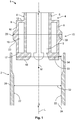
Fig. 1 there is depicted a schematic sectional view of an inventiveelectric plug 1 before mounting. - The
electric plug 1 has aninner housing 4 which can be plugged into anouter housing 2 along an assembly direction M. - The
inner housing 4 can be, for example, a plug strip or a chamber block, which can be connected to a complementary plug (not shown). For this purpose, theinner housing 4 is punctuated bycontact receptacles 5 along the longitudinal axis L. Theinner housing 4 has anelongate base body 6, which extends along a longitudinal axis L arranged substantially parallel to the assembly direction M. Theelongate base body 6 is bounded by fourlateral surfaces 7 transversely to the assembly direction M, twoadjacent lateral surfaces 7 being arranged at substantially 90° to one another on eachlateral surface 7. As a result, thebase body 6 has a substantially rectangular cross-section transverse to the assembly direction M. Press-onelements 8 are overmoulded on the lateral surfaces 7. Theinner housing 4 and the press-onelements 8 are formed integrally as amonolithic component 10 and can be moulded from a plastic, for example by means of injection moulding. - The elastic press-on
elements 8 can be deflected elastically transversely to the assembly direction M and serve to compensate a tolerance between theinner housing 4 and theouter housing 2 transversely to the assembly direction M and to couple theinner housing 4 and theouter housing 2 to one another by way of a press-fit connection. - The elastic press-on
element 8 has abracket 12, which extends outwardly from thelateral surface 7 transversely to the assembly direction M. At the end 14 of thebracket 12 facing away from thelateral surface 7 there is arranged aspring tab 16, which extends substantially by 90° away from thebracket 12 along the assembly direction M, and ends in front of an offset 17 of anend surface 18 of theinner housing 4, which end surface faces theouter housing 2 in the assembly direction M. As a result, arecess 19 is produced between thespring tab 16 and thelateral surface 7, and the press-onelement 8 has a substantially L-shaped cross-section. In an exemplary configuration that is not shown, thespring tab 16 can extend from onebracket 12 to asecond bracket 12, such that the press-on element has a substantially U-shaped cross-section. - The
spring tab 16 is provided with a contact-pressure surface 20 extending transversely to the longitudinal axis L away from theinner housing 4. In the mounted state, the contact-pressure surface 20 presses against asupport surface 22 of theouter housing 2, in order to produce a press-fit connection between theinner housing 4 and theouter housing 2. During the mounting, a normal force acts upon the contact-pressure surface 20 and thespring tab 16 is deflected transversely to the assembly direction M in the direction of theinner housing 4. The contact-pressure surface 20 tapers in the direction of thesupport surface 22, and thus has achamfer 23 at the edge. Thechamfer 23 runs along the longitudinal axis L and facilitates the plugging-in in the assembly direction M, as a small resistance must be overcome in comparison with a stepped configuration. - The
outer housing 2 has areceptacle 24 into which theinner housing 4 can be inserted. Thereceptacle 24 is bounded transversely to the assembly direction M by way of lateral walls 26 and has a substantially rectangular cross-section and is configured in a manner which is complementary to theinner housing 4. Thesupport surface 22 of theouter housing 2 is formed by aprominent portion 28 protruding in the direction of theinner housing 4. - In this exemplary configuration, the
outer housing 2 is water-tight and surrounds theinner housing 4 in a protective manner after mounting. - The
inner housing 4 has aninternal width 30 transverse to the assembly direction M between two contact-pressure surfaces 20 arranged on oppositelateral surfaces 7 in relation to theinner housing 4, this internal width being greater than aninternal width 32 between the opposite support surfaces 22 of theouter housing 2. Theinternal width 33 of theinner housing 4 without contact-pressure surfaces 20 is smaller than theinternal width 32, as a result of which agap 34 would arise betweeninner housing 4 andouter housing 2 during plugging-together without press-onelements 8. By way of the press-onelement 8, when the plugging-together is carried out at the position, thegap 34 is closed by the contact-pressure surface 20 and thesupport surface 22 is contacted. As a result, theinner housing 4 can be fixed in a play-free manner in theouter housing 2. - During the mounting, the press-on
element 8 is deflected elastically by the overdimension transversely to the assembly direction M in the direction of theinner housing 4. In the process, the press-onelement 8 presses with its contact-pressure surface 20 against the correspondingsupport surface 22 and produces a press-fit connection between theouter housing 2 and theinner housing 4 by means of the spring force. In the mounted state, theinternal width 30 of theinner housing 4 corresponds substantially to theinternal width 32 of theouter housing 2. A tolerance is compensated by the elastic press-onelements 8. As a result, it is possible to fix theinner housing 4 in theouter housing 2 in a play-free manner. Furthermore, high plugging forces during mounting, owing to an overpressing, are reduced in an undefined manner by the elastic press-onelements 8. During mounting, the elastic press-onelements 8 are deflected in the direction of thelateral surface 7 of theinner housing 4 by the overdimension between theinternal width 30 and theinternal width 32, and thus prevent an overpressing. - In order to produce a stable press-fit connection, the material thickness of the contact-
pressure surface 20 transverse to the assembly direction M is greater than the width of thegap 34 transverse to the assembly direction M. - In this preferred configuration, a press-on
element 8 is moulded on eachlateral surface 7 of theinner housing 4. As a result, a secure and tilt-free fixing of theinner housing 4 in theouter housing 2 can be ensured. Depending on spatial conditions and dimensions of theelectric plug 1, at least one press-onelement 8 can be arranged on alateral surface 6, at least two press-onelements 8 can be arranged on two mutually adjacentlateral surfaces 7 or two mutually oppositelateral surfaces 7 with respect to theinner housing 4 or at least three press-onelements 8 can be arranged on threelateral surfaces 7. Furthermore, the press-onelements 8 can be arranged on theouter housing 2 and theinner housing 4 can be provided with complementary support surfaces 22. Thesupport surface 22 can be alateral surface 7 directly or can be formed by a prominent portion in the direction of the contact-pressure surface 20. Moreover, several mutually spaced-apart press-onelements 8 can be arranged on alateral surface 7 along the longitudinal axis L. - Preferably, all
lateral surfaces 6 are provided with at least two press-onelements 8, one press-onelement 8 in each case being arranged at an end of thelateral surface 7 lying along the longitudinal axis L. As a result, tilting of theinner housing 4 is prevented. - A schematic sectional view of a further inventive
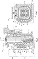
electric plug 1 is depicted inFig. 2 and Fig. 3 in each case. - In this configuration, the
outer housing 2 is constructed from twoseparate housing parts rear housing part 35 in the assembly direction M is partly surrounded by thefront housing part 36 in the assembly direction M, and is connected to thefront housing part 36 in a play-free manner by means of a press-fit connection produced by a press-onelement 8. - The
inner housing 4 is inserted into therear housing part 35 in the assembly direction M and is fixed by means of a press-fit connection produced by at least one press-onelement 8. In this case, a press-onelement 8 with aspring tab 16 extends in each case across a rounded corner 38 between twoadjacent lateral surfaces 6 which are arranged at substantially 90° to one another. The press-onelement 8 is by acollar 37, which is provided with arecess 19 extending across the corner 38. As a result, at each corner 38 aspring tab 16 is arranged between thesupport surface 22 at the lateral wall 26 of therear housing part 35 and therecess 18. Thespring tabs 16 are in each case provided with a contact-pressure surface 20 protruding in the direction of thesupport surface 22. The contact-pressure surface 20 has the shape of a segment of a sphere, the apex being directed towards thesupport surface 22. Thus, the contact-pressure surface 20 is complementary to thesupport surface 22, which is formed by the rounded corner between the mutually adjacent lateral walls 26. - In
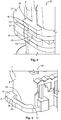
Fig. 3 , it can be seen that agap 34 extends between the inner housing and therear housing part 35. The contact-pressure surface 20 projects into thisgap 34 and is supported on thesupport surface 22 of therear housing part 35 and thus fixes theinner housing 4 in therear housing part 35 in a play-free manner by means of a press-fit connection. - The
spring tab 16 can be deflected in the direction of therecess 19, in order to avoid high plugging forces, owing to an overpressing, when plugging theinner housing 4 into therear housing part 35. - The
inner housing 4 has anelongate base body 6 along the assembly direction M and is punctuated by fourcontact receptacles 5 along the longitudinal axis L. Thecontact receptacles 5 are arranged in a square and in each case can receive a contact of a complementary mating plug. The base body has arear section 40 which is enclosed by therear housing part 35 and in the assembly direction M, which rear section has aninternal width 30 transverse to the assembly direction M, which internal width is approximately as large as theinternal width 32 of the receptacle of therear housing part 35, in order to ensure play-free fixing of theinner housing 4 and of therear housing part 35. - The rear section is preferably provided with elastic press-on
elements 8 on thelateral surfaces 7 in each case on the front and rear ends in the assembly direction M. As a result, tilting of theinner housing 4 in therear housing part 35 is prevented. - The
elongate base body 6 narrows uniformly with a step 42 which runs around thebase body 6 transversely to the assembly direction M. The narrowedsection 44 extends from the step 42 counter to the assembly direction M and forms the front end of theelongate base body 6 in the assembly direction M. - The
rear section 40 is surrounded by therear housing part 35. Thefront housing part 36 extends along the longitudinal axis L and is plugged onto theinner housing 4 in the assembly direction M. For this purpose, thefront housing part 36 is punctuated by an opening along the longitudinal axis L. Theopening 46 is bounded by awall 47 transversely to the assembly direction M and has a substantially rectangular cross-section transverse to the assembly direction M. Theopening 46 has a contour which is complementary to the narrowedsection 44. Further elastic press-onelements 8 can be arranged on the narrowedsection 40, in order to produce a play-free and tilt-free fixing of theinner housing 4 in thefront housing part 36. Thefront housing part 36 extends along the longitudinal axis L in the assembly direction M as far as the limit stop on the step 42. - At the limit stop on the step 42, the
front housing part 36 has ashoulder 48 with which theopening 46 is widened, and extends further in the assembly direction M. In the process, thefront housing part 36 surrounds therear housing part 35. Thefront housing part 36 is provided with ahousing interlock 50 on one side transversely to the assembly direction M, which housing interlock has a latching arm which can be latched on a latching nose of therear housing part 35, which latching nose stands proud of the lateral wall transversely to the assembly direction M. As a result, inadvertent opening during operation and theinner housing 4 slipping out counter to the assembly direction M is prevented. - Furthermore, the
front housing part 36 is provided with an elastic press-onelement 8 on at least one side of theopening 46 transversely to the assembly direction M, this elastic press-on element being moulded from thewall 47 of thefront housing part 36. The elastic press-onelement 8 has aspring tab 16, which extends along the longitudinal axis L and protrudes in the direction of the lateral wall 26 of therear housing part 35 transversely to the assembly direction M and is pressed against an outer surface of the lateral wall 26 of therear housing part 35, which outer surface is directed towards the wall of thefront housing part 36. In this configuration, the material thickness of thespring tab 16 corresponds to the material thickness of thewall 47. As a result, thefront housing part 36 is connected to therear housing part 35 by means of a press-fit connection produced by the elastic press-onelement 8. - The
spring tab 16 is moulded by a cutout of thewall 47, which cutout extends along the longitudinal axis L, and is connected to thewall 47 at both ends 51, 52 lying along the longitudinal axis L. Thespring tab 16 has a contact-pressure surface 20 which extends substantially parallel to the longitudinal axis L, and twospring arms end pressure surface 20, at an angle which is inclined with respect to therear housing part 35 of the longitudinal axis L, and terminate at this contact-pressure surface. As a result, the elasticity of the press-onelement 8 transverse to the assembly direction M is ensured by thespring arms - By way of the elastic press-on
element 8, a tolerance between the elements to be plugged in and the receiving elements can be overcome. The tolerance can, on the one hand, lead to an overpressing, as a result of which indefinably high plugging forces arise, and on the other hand, lead to play between the elements can occur, as a result of which these elements can be damaged by movement and vibrations. By way of the elastic press-onelements 8, when there is an overpressing, the press-onelement 8 is deflected in the direction of the normal force acting upon the press-onelement 8 during plugging-in, and the high plugging forces owing to the overpressing are reduced. Furthermore, the play in the plugged state is set to zero by the press-onelements 8, which produce a press-fit connection between theinner housing 4 and theouter housing 2 or between thefront housing part 36 and therear housing part 35 of theouter housing 2. - The dismounting and maintenance of the
electric plug 1 is simplified on account of the press-fit connection, as only a low tensile force is required in order to remove theinner housing 4 from theouter housing 2, for example. -
Fig. 4 shows a further advantageous configuration of a press-onelement 8 for aninventive plug 1. - The press-on
element 8 is moulded by twocollars 37 which run around theinner housing 4, project transversely to the assembly direction M and are spaced apart from one another in the assembly direction M. Thecollars 37 are arranged parallel to one another and are punctuated by arecess 19 on at least onelateral surface 7 of theinner housing 4 in the assembly direction M. Therecess 7 extends transversely to the assembly direction M parallel to thelateral surface 7. - As a result, each
collar 37 has aspring tab 16 between therecess 19 and the end of thecollar 37 facing away from thelateral surface 7 of theinner housing 4, which spring tab extends transversely to the assembly direction M parallel to thelateral surface 7. Thus, the press-onelement 8 has a substantially U-shaped cross-section transverse to the assembly direction M. - The
spring tabs 16 are provided with a contact-pressure surface 20 which projects away in the assembly direction M and connects the twospring tabs 16 to one another in the direction of thelateral surface 7. The contact-pressure surface 20 in this case extends between the surfaces of thespring tabs 16 facing one another and on the surface of thespring tabs 16 facing away from thelateral surface 7. The contact-pressure surface 20 terminates, in the assembly direction M and counter to the assembly direction M, in achamfer 23 running towards the surface of thespring tab 16 facing away from thelateral surface 7, in order to facilitate a plugging-in and unplugging. -
Fig. 5 shows a further advantageous configuration of a press-onelement 8 of an inventiveelectric plug 1. - The press-on
element 8 is arranged on aninner housing 4 on alateral surface 7 at theend 58 lying to the rear in the assembly direction M. - The press-on
element 8 has twobrackets 12 arranged parallel to one another, which project from thelateral surface 7 of theinner housing 4 at opposite corners 38 of thelateral surface 7 transversely to the assembly directionM. The brackets 12 are connected to one another by means of aspring tab 16, which extends transversely to the assembly direction M. As a result, thespring tab 16 is spaced apart from thelateral surface 7 transversely to the assembly direction M by means of arecess 19, which extends between thebrackets 12 and betweenlateral surface 7 andspring tab 16. - The press-on
element 8 has a substantially U-shaped cross-section transverse to the assembly direction M. Thespring tab 16 here can be deflected in the direction of thereceptacle 16 when there is an application of force. As a result, a high plugging force, as a result of an overdimension, is prevented. Thespring tab 16 is provided with a contact-pressure surface 20 protruding in the direction away from thelateral surface 7, with which contact-pressure surface theinner housing 4 is supported on the oppositeouter housing 2 when theplug 1 is plugged-together. - Depending on dimension and spatial conditions of the
plug 1, differently configured press-onelements 8 can be arranged on theinner housing 4 and/or on theouter housing 2. -
- 1
- electric plug
- 2
- outer housing
- 4
- inner housing
- 5
- contact receptacle
- 6
- elongate base body
- 7
- lateral surface of the inner housing
- 8
- elastic press-on element
- 10
- monolithic component
- 12
- bracket
- 14
- end of the bracket facing away from the lateral surface
- 16
- spring tab
- 17
- offset
- 18
- end surface
- 19
- recess
- 20
- contact-pressure surface
- 22
- support surface
- 23
- chamfer
- 24
- receptacle
- 26
- lateral surface of the outer housing
- 28
- prominent portion
- 30
- internal width of the inner housing
- 32
- internal width of the receptacle of the outer housing
- 33
- internal width of the inner housing without press-on element
- 34
- gap
- 35
- rear housing part
- 36
- front housing part
- 37
- collar
- 38
- rounded corner
- 40
- rear section
- 42
- step
- 44
- narrowed section
- 46
- opening
- 47
- wall
- 48
- shoulder
- 50
- housing interlock
- 51
- end of the press-on element
- 52
- end of the press-on element
- 54
- spring arm
- 56
- spring arm
- 58
- end of the inner housing
- L
- longitudinal axis
- M
- assembly direction
Claims (15)
- An electric plug (1) having an outer housing (2) and an inner housing (4) which can be plugged into the outer housing (2) along an assembly direction (M), characterised by at least one press-on element (8), which can be deflected elastically transversely to the assembly direction (M), and a press-fit connection, which is produced by the at least one press-on element (8), between the inner housing (4) and the outer housing (2).
- The electric plug (1) according to Claim 1, characterised in that at least one press-on element (8) is fitted to the inner housing (4) and/or to the outer housing (2) between the inner housing (4) and the outer housing (2).
- The electric plug (1) according to Claim 1 or Claim 2, characterised in that the at least one press-on element (8) extends transversely to the assembly direction (M) across a gap (34) between the inner housing (4) and the outer housing (2).
- The electric plug (1) according to any one of Claims 1 to 3, characterised in that the inner housing (4) or the outer housing (2) are formed integrally as a monolithic component (10) with the at least one press-on element (8).
- The electric plug (1) according to any one of Claims 1 to 4, characterised in that at least two press-on elements (8) are arranged on two mutually adjacent lateral surfaces (7) between inner housing (4) and outer housing (2).
- The electric plug (1) according to any one of Claims 1 to 5, characterised in that at least two press-on elements (8) are arranged on mutually opposite lateral surfaces (7) between inner housing (4) and outer housing (2).
- The electric plug (1) according to any one of Claims 1 to 6, characterised in that at least one press-on element (8) extends across a corner (38) of two mutually adjacent lateral surfaces (7).
- The electric plug (1) according to any one of Claims 1 to 7, characterised in that the at least one press-on element (8) has a spring tab (16).
- The electric plug (1) according to any one of Claims 1 to 8, characterised in that the at least one press-on element (8) is provided with at least one bracket (12) which projects from the outer housing (2) to the inner housing (4) or from the inner housing (4) to the outer housing (2).
- The electric plug (1) according to any one of Claims 1 to 9, characterised in that a projecting contact-pressure surface (20) is arranged on the at least one press-on element (8), on which contact-pressure surface the press-on element (8) is supported on the opposite outer housing (2) or inner housing (4) in the case of the plugged-together plug (1).
- The electric plug according to Claim 10, characterised in that the contact-pressure surface (20) is configured in a manner which is complementary to the support surface (22) on the opposite outer housing (2) or inner housing (4).
- The electric plug (1) according to any one of Claims 1 to 11, characterised in that the at least one press-on element (8) has a substantially U-shaped cross-section in the assembly direction (M).
- The electric plug (1) according to any one of Claims 1 to 12, characterised in that the at least one press-on element (8) is moulded from a wall of the outer housing (2) or of the inner housing (4).
- An inner housing (4) having a base body (6) which extends along a longitudinal axis (L), which base body is configured such that it can be inserted into an outer housing (2) in an assembly direction (M), characterised by a press-on element (8), which can be deflected transversely to the assembly direction (M) in the direction of the inner housing (4), for producing a press-fit connection between the inner housing (4) and the outer housing (2).
- An outer housing (2) having a receptacle (24) for receiving an inner housing (4), characterised by a press-on element (8), which is arranged in the receptacle (24) and can be deflected in the direction of the outer housing (2), for producing a press-fit connection between the inner housing (4) and the outer housing (2).
Applications Claiming Priority (1)
| Application Number | Priority Date | Filing Date | Title |
|---|---|---|---|
| DE102018203628.4A DE102018203628A1 (en) | 2018-03-09 | 2018-03-09 | Electrical plug with elastic pressure elements |
Publications (2)
| Publication Number | Publication Date |
|---|---|
| EP3537547A1 true EP3537547A1 (en) | 2019-09-11 |
| EP3537547B1 EP3537547B1 (en) | 2021-08-18 |
Family
ID=65685250
Family Applications (1)
| Application Number | Title | Priority Date | Filing Date |
|---|---|---|---|
| EP19160524.5A Active EP3537547B1 (en) | 2018-03-09 | 2019-03-04 | Inner housing and outer housing of an electric plug |
Country Status (6)
| Country | Link |
|---|---|
| US (1) | US10777932B2 (en) |
| EP (1) | EP3537547B1 (en) |
| JP (1) | JP7442973B2 (en) |
| KR (1) | KR20190106810A (en) |
| CN (1) | CN110247236B (en) |
| DE (1) | DE102018203628A1 (en) |
Families Citing this family (2)
| Publication number | Priority date | Publication date | Assignee | Title |
|---|---|---|---|---|
| US20220045460A1 (en) * | 2020-08-05 | 2022-02-10 | TE Connectivity Services Gmbh | Housing for a connector of a connector system |
| DE102020210496B3 (en) * | 2020-08-19 | 2021-12-16 | Robert Bosch Gesellschaft mit beschränkter Haftung | Adapter plug and electronic assembly with an adapter plug |
Citations (3)
| Publication number | Priority date | Publication date | Assignee | Title |
|---|---|---|---|---|
| EP1758205A2 (en) * | 2005-08-23 | 2007-02-28 | Thomas & Betts International, Inc. | Coaxial cable connector with friction-fit sleeve |
| US7189114B1 (en) * | 2006-06-29 | 2007-03-13 | Corning Gilbert Inc. | Compression connector |
| US20140106597A1 (en) * | 2011-06-23 | 2014-04-17 | Tyco Electronics Amp Gmbh | Connector Assembly With Chamber Block And Contact Position Assurance |
Family Cites Families (38)
| Publication number | Priority date | Publication date | Assignee | Title |
|---|---|---|---|---|
| JP2896783B2 (en) * | 1989-03-01 | 1999-05-31 | 日本航空電子工業株式会社 | Double lock structure of connector housing |
| JP2746012B2 (en) * | 1992-10-21 | 1998-04-28 | 住友電装株式会社 | connector |
| US5326280A (en) * | 1993-06-14 | 1994-07-05 | Amphenol Corporation | Coaxial connector with integral decoupling unit |
| US5362261A (en) * | 1993-06-30 | 1994-11-08 | The Whitaker Corporation | Hybrid connector |
| DE19530505B4 (en) | 1995-08-18 | 2004-12-30 | The Whitaker Corp., Wilmington | Electrical plug with a housing and a chamber block |
| US5876231A (en) * | 1996-09-10 | 1999-03-02 | Framatome Connectors Usa | Connector for airbag system |
| DE19647021A1 (en) * | 1996-11-14 | 1998-05-20 | Teves Gmbh Alfred | Connector with a plug, an intermediate part and a housing |
| US6027360A (en) * | 1998-06-10 | 2000-02-22 | Yazaki Corporation | Junction block bracket for floating connector attachment |
| JP3500065B2 (en) * | 1998-06-25 | 2004-02-23 | 矢崎総業株式会社 | Waterproof connector |
| US6129563A (en) * | 1998-11-18 | 2000-10-10 | The Whitaker Corporation | Bulkhead-mountable coaxial connector |
| US6095852A (en) * | 1998-12-17 | 2000-08-01 | Yazaki North America, Inc. | Connector bracket wire shield with connector retention arms |
| US6332784B1 (en) * | 2000-06-02 | 2001-12-25 | David Oliphant | Housing for a communications card |
| US6793400B2 (en) * | 2002-01-11 | 2004-09-21 | Fci Americas Technology, Inc. | Floating connector clip |
| JP3959058B2 (en) * | 2002-10-09 | 2007-08-15 | 矢崎総業株式会社 | connector |
| JP2005203307A (en) * | 2004-01-19 | 2005-07-28 | Yazaki Corp | Connector |
| US7118414B2 (en) * | 2004-01-22 | 2006-10-10 | Northstar Systems, Inc. | Computer input/output connector assembly |
| FR2874751A1 (en) * | 2004-08-30 | 2006-03-03 | Fci Sa | ELECTRICAL CONNECTOR ADAPTED FOR MITIGATING VIBRATION, IN PARTICULAR FOR A MOTOR VEHICLE INJECTOR |
| JP4427748B2 (en) * | 2005-02-28 | 2010-03-10 | 住友電装株式会社 | connector |
| US7125290B2 (en) * | 2005-03-28 | 2006-10-24 | Tyco Electronics Corporation | Connector system with polarization and latching features |
| JP4941745B2 (en) * | 2007-06-19 | 2012-05-30 | 住友電装株式会社 | connector |
| JP5002485B2 (en) * | 2008-02-22 | 2012-08-15 | 矢崎総業株式会社 | connector |
| CN201252175Y (en) * | 2008-08-04 | 2009-06-03 | 富士康(昆山)电脑接插件有限公司 | Cable connector component |
| CN101478098B (en) * | 2008-12-31 | 2011-02-09 | 中航光电科技股份有限公司 | Connector |
| JP5303378B2 (en) * | 2009-06-26 | 2013-10-02 | 矢崎総業株式会社 | Standby connector |
| JP5399804B2 (en) * | 2009-08-03 | 2014-01-29 | 矢崎総業株式会社 | connector |
| DE102009048481B4 (en) | 2009-10-07 | 2020-02-20 | Kostal Kontakt Systeme Gmbh | Electrical connector |
| CN201708364U (en) * | 2009-11-10 | 2011-01-12 | 富士康(昆山)电脑接插件有限公司 | Cable connector assembly |
| CN201570596U (en) * | 2009-11-20 | 2010-09-01 | 富港电子(东莞)有限公司 | Electric connector |
| KR101615388B1 (en) * | 2010-05-20 | 2016-04-25 | 스미토모 덴소 가부시키가이샤 | Connector |
| JP5635338B2 (en) * | 2010-08-31 | 2014-12-03 | 矢崎総業株式会社 | connector |
| US8333613B2 (en) * | 2011-02-15 | 2012-12-18 | Tyco Electronics Corporation | Header assembly |
| JP5673320B2 (en) * | 2011-04-18 | 2015-02-18 | 株式会社オートネットワーク技術研究所 | connector |
| JP5941374B2 (en) * | 2012-08-24 | 2016-06-29 | 矢崎総業株式会社 | Connector for reducing insertion / extraction force |
| US9300087B2 (en) * | 2013-10-14 | 2016-03-29 | Trane International Inc. | Mountable cable interface |
| US9853391B2 (en) * | 2015-09-01 | 2017-12-26 | Sumitomo Wiring Systems, Ltd. | Wire connector with integrated coaxial connection and front loaded terminal position assurance structures |
| JP2018022629A (en) * | 2016-08-04 | 2018-02-08 | 日本圧着端子製造株式会社 | Connector member and connector |
| CN106848751B (en) * | 2016-12-22 | 2024-03-12 | 普罗斯通信技术(苏州)有限公司 | Self-locking type connecting mechanism |
| US10044142B1 (en) * | 2017-04-28 | 2018-08-07 | Valeo North America, Inc. | Connector locking holder |
-
2018
- 2018-03-09 DE DE102018203628.4A patent/DE102018203628A1/en not_active Ceased
-
2019
- 2019-03-04 EP EP19160524.5A patent/EP3537547B1/en active Active
- 2019-03-07 JP JP2019041115A patent/JP7442973B2/en active Active
- 2019-03-08 KR KR1020190026927A patent/KR20190106810A/en not_active Application Discontinuation
- 2019-03-08 CN CN201910174209.2A patent/CN110247236B/en active Active
- 2019-03-08 US US16/297,018 patent/US10777932B2/en active Active
Patent Citations (3)
| Publication number | Priority date | Publication date | Assignee | Title |
|---|---|---|---|---|
| EP1758205A2 (en) * | 2005-08-23 | 2007-02-28 | Thomas & Betts International, Inc. | Coaxial cable connector with friction-fit sleeve |
| US7189114B1 (en) * | 2006-06-29 | 2007-03-13 | Corning Gilbert Inc. | Compression connector |
| US20140106597A1 (en) * | 2011-06-23 | 2014-04-17 | Tyco Electronics Amp Gmbh | Connector Assembly With Chamber Block And Contact Position Assurance |
Also Published As
| Publication number | Publication date |
|---|---|
| US20190280418A1 (en) | 2019-09-12 |
| CN110247236A (en) | 2019-09-17 |
| DE102018203628A1 (en) | 2019-09-12 |
| JP2019165000A (en) | 2019-09-26 |
| CN110247236B (en) | 2022-11-18 |
| US10777932B2 (en) | 2020-09-15 |
| EP3537547B1 (en) | 2021-08-18 |
| JP7442973B2 (en) | 2024-03-05 |
| KR20190106810A (en) | 2019-09-18 |
Similar Documents
| Publication | Publication Date | Title |
|---|---|---|
| US10483674B2 (en) | Electrical connector for circuit boards and manufacturing method thereof | |
| US8540534B2 (en) | Connector | |
| JP7161463B2 (en) | Electrical connector and manufacturing method thereof | |
| JP2012156090A (en) | Floating type connector | |
| US20180241155A1 (en) | Movable connector | |
| KR101851491B1 (en) | Connector and connection structure | |
| EP3537547A1 (en) | Electric plug with elastic press-on elements | |
| EP3930100A1 (en) | Connector | |
| JP7185662B2 (en) | Connector manufacturing method and connector | |
| JP2012164520A (en) | Relay connector | |
| US20230378682A1 (en) | Terminal unit | |
| JP7377781B2 (en) | Electrical connector and its manufacturing method | |
| KR20220107946A (en) | Connector with insert-molded terminal | |
| JP2011048982A (en) | Floating connector | |
| US20140187098A1 (en) | Connector | |
| KR101001890B1 (en) | Coupling connector and connector assambly for board to board using the same | |
| CN109600955B (en) | Substrate holding structure | |
| JP2018116825A (en) | connector | |
| KR101283277B1 (en) | Two-row angled pin connector | |
| US20230246356A1 (en) | Circuit board electrical connector | |
| JP7164947B2 (en) | movable connector | |
| JP2001135401A (en) | Construction for positioning core terminal | |
| TW202333427A (en) | Connector | |
| JP3976371B2 (en) | Busbar holding part structure for insert | |
| WO2008062732A1 (en) | Electric connector assembly |
Legal Events
| Date | Code | Title | Description |
|---|---|---|---|
| PUAI | Public reference made under article 153(3) epc to a published international application that has entered the european phase |
Free format text: ORIGINAL CODE: 0009012 |
|
| STAA | Information on the status of an ep patent application or granted ep patent |
Free format text: STATUS: THE APPLICATION HAS BEEN PUBLISHED |
|
| AK | Designated contracting states |
Kind code of ref document: A1 Designated state(s): AL AT BE BG CH CY CZ DE DK EE ES FI FR GB GR HR HU IE IS IT LI LT LU LV MC MK MT NL NO PL PT RO RS SE SI SK SM TR |
|
| AX | Request for extension of the european patent |
Extension state: BA ME |
|
| STAA | Information on the status of an ep patent application or granted ep patent |
Free format text: STATUS: REQUEST FOR EXAMINATION WAS MADE |
|
| 17P | Request for examination filed |
Effective date: 20200304 |
|
| RBV | Designated contracting states (corrected) |
Designated state(s): AL AT BE BG CH CY CZ DE DK EE ES FI FR GB GR HR HU IE IS IT LI LT LU LV MC MK MT NL NO PL PT RO RS SE SI SK SM TR |
|
| GRAP | Despatch of communication of intention to grant a patent |
Free format text: ORIGINAL CODE: EPIDOSNIGR1 |
|
| STAA | Information on the status of an ep patent application or granted ep patent |
Free format text: STATUS: GRANT OF PATENT IS INTENDED |
|
| GRAJ | Information related to disapproval of communication of intention to grant by the applicant or resumption of examination proceedings by the epo deleted |
Free format text: ORIGINAL CODE: EPIDOSDIGR1 |
|
| GRAP | Despatch of communication of intention to grant a patent |
Free format text: ORIGINAL CODE: EPIDOSNIGR1 |
|
| RIC1 | Information provided on ipc code assigned before grant |
Ipc: H01R 13/504 20060101ALI20210224BHEP Ipc: H01R 13/52 20060101ALN20210224BHEP Ipc: H01R 13/502 20060101AFI20210224BHEP Ipc: H01R 13/506 20060101ALN20210224BHEP Ipc: H01R 13/516 20060101ALI20210224BHEP |
|
| RIC1 | Information provided on ipc code assigned before grant |
Ipc: H01R 13/506 20060101ALN20210302BHEP Ipc: H01R 13/52 20060101ALN20210302BHEP Ipc: H01R 13/504 20060101ALI20210302BHEP Ipc: H01R 13/502 20060101AFI20210302BHEP Ipc: H01R 13/516 20060101ALI20210302BHEP |
|
| INTG | Intention to grant announced |
Effective date: 20210317 |
|
| RIC1 | Information provided on ipc code assigned before grant |
Ipc: H01R 13/52 20060101ALN20210305BHEP Ipc: H01R 13/506 20060101ALN20210305BHEP Ipc: H01R 13/516 20060101ALI20210305BHEP Ipc: H01R 13/504 20060101ALI20210305BHEP Ipc: H01R 13/502 20060101AFI20210305BHEP |
|
| INTG | Intention to grant announced |
Effective date: 20210330 |
|
| GRAS | Grant fee paid |
Free format text: ORIGINAL CODE: EPIDOSNIGR3 |
|
| GRAA | (expected) grant |
Free format text: ORIGINAL CODE: 0009210 |
|
| STAA | Information on the status of an ep patent application or granted ep patent |
Free format text: STATUS: THE PATENT HAS BEEN GRANTED |
|
| AK | Designated contracting states |
Kind code of ref document: B1 Designated state(s): AL AT BE BG CH CY CZ DE DK EE ES FI FR GB GR HR HU IE IS IT LI LT LU LV MC MK MT NL NO PL PT RO RS SE SI SK SM TR |
|
| REG | Reference to a national code |
Ref country code: GB Ref legal event code: FG4D |
|
| REG | Reference to a national code |
Ref country code: CH Ref legal event code: EP |
|
| REG | Reference to a national code |
Ref country code: DE Ref legal event code: R096 Ref document number: 602019006883 Country of ref document: DE |
|
| REG | Reference to a national code |
Ref country code: IE Ref legal event code: FG4D Ref country code: AT Ref legal event code: REF Ref document number: 1422472 Country of ref document: AT Kind code of ref document: T Effective date: 20210915 |
|
| REG | Reference to a national code |
Ref country code: LT Ref legal event code: MG9D |
|
| REG | Reference to a national code |
Ref country code: NL Ref legal event code: MP Effective date: 20210818 |
|
| REG | Reference to a national code |
Ref country code: AT Ref legal event code: MK05 Ref document number: 1422472 Country of ref document: AT Kind code of ref document: T Effective date: 20210818 |
|
| PG25 | Lapsed in a contracting state [announced via postgrant information from national office to epo] |
Ref country code: SE Free format text: LAPSE BECAUSE OF FAILURE TO SUBMIT A TRANSLATION OF THE DESCRIPTION OR TO PAY THE FEE WITHIN THE PRESCRIBED TIME-LIMIT Effective date: 20210818 Ref country code: RS Free format text: LAPSE BECAUSE OF FAILURE TO SUBMIT A TRANSLATION OF THE DESCRIPTION OR TO PAY THE FEE WITHIN THE PRESCRIBED TIME-LIMIT Effective date: 20210818 Ref country code: ES Free format text: LAPSE BECAUSE OF FAILURE TO SUBMIT A TRANSLATION OF THE DESCRIPTION OR TO PAY THE FEE WITHIN THE PRESCRIBED TIME-LIMIT Effective date: 20210818 Ref country code: FI Free format text: LAPSE BECAUSE OF FAILURE TO SUBMIT A TRANSLATION OF THE DESCRIPTION OR TO PAY THE FEE WITHIN THE PRESCRIBED TIME-LIMIT Effective date: 20210818 Ref country code: PT Free format text: LAPSE BECAUSE OF FAILURE TO SUBMIT A TRANSLATION OF THE DESCRIPTION OR TO PAY THE FEE WITHIN THE PRESCRIBED TIME-LIMIT Effective date: 20211220 Ref country code: NO Free format text: LAPSE BECAUSE OF FAILURE TO SUBMIT A TRANSLATION OF THE DESCRIPTION OR TO PAY THE FEE WITHIN THE PRESCRIBED TIME-LIMIT Effective date: 20211118 Ref country code: HR Free format text: LAPSE BECAUSE OF FAILURE TO SUBMIT A TRANSLATION OF THE DESCRIPTION OR TO PAY THE FEE WITHIN THE PRESCRIBED TIME-LIMIT Effective date: 20210818 Ref country code: AT Free format text: LAPSE BECAUSE OF FAILURE TO SUBMIT A TRANSLATION OF THE DESCRIPTION OR TO PAY THE FEE WITHIN THE PRESCRIBED TIME-LIMIT Effective date: 20210818 Ref country code: BG Free format text: LAPSE BECAUSE OF FAILURE TO SUBMIT A TRANSLATION OF THE DESCRIPTION OR TO PAY THE FEE WITHIN THE PRESCRIBED TIME-LIMIT Effective date: 20211118 Ref country code: LT Free format text: LAPSE BECAUSE OF FAILURE TO SUBMIT A TRANSLATION OF THE DESCRIPTION OR TO PAY THE FEE WITHIN THE PRESCRIBED TIME-LIMIT Effective date: 20210818 |
|
| PG25 | Lapsed in a contracting state [announced via postgrant information from national office to epo] |
Ref country code: PL Free format text: LAPSE BECAUSE OF FAILURE TO SUBMIT A TRANSLATION OF THE DESCRIPTION OR TO PAY THE FEE WITHIN THE PRESCRIBED TIME-LIMIT Effective date: 20210818 Ref country code: LV Free format text: LAPSE BECAUSE OF FAILURE TO SUBMIT A TRANSLATION OF THE DESCRIPTION OR TO PAY THE FEE WITHIN THE PRESCRIBED TIME-LIMIT Effective date: 20210818 Ref country code: GR Free format text: LAPSE BECAUSE OF FAILURE TO SUBMIT A TRANSLATION OF THE DESCRIPTION OR TO PAY THE FEE WITHIN THE PRESCRIBED TIME-LIMIT Effective date: 20211119 |
|
| PG25 | Lapsed in a contracting state [announced via postgrant information from national office to epo] |
Ref country code: NL Free format text: LAPSE BECAUSE OF FAILURE TO SUBMIT A TRANSLATION OF THE DESCRIPTION OR TO PAY THE FEE WITHIN THE PRESCRIBED TIME-LIMIT Effective date: 20210818 |
|
| PG25 | Lapsed in a contracting state [announced via postgrant information from national office to epo] |
Ref country code: DK Free format text: LAPSE BECAUSE OF FAILURE TO SUBMIT A TRANSLATION OF THE DESCRIPTION OR TO PAY THE FEE WITHIN THE PRESCRIBED TIME-LIMIT Effective date: 20210818 |
|
| REG | Reference to a national code |
Ref country code: DE Ref legal event code: R097 Ref document number: 602019006883 Country of ref document: DE |
|
| PG25 | Lapsed in a contracting state [announced via postgrant information from national office to epo] |
Ref country code: SM Free format text: LAPSE BECAUSE OF FAILURE TO SUBMIT A TRANSLATION OF THE DESCRIPTION OR TO PAY THE FEE WITHIN THE PRESCRIBED TIME-LIMIT Effective date: 20210818 Ref country code: SK Free format text: LAPSE BECAUSE OF FAILURE TO SUBMIT A TRANSLATION OF THE DESCRIPTION OR TO PAY THE FEE WITHIN THE PRESCRIBED TIME-LIMIT Effective date: 20210818 Ref country code: RO Free format text: LAPSE BECAUSE OF FAILURE TO SUBMIT A TRANSLATION OF THE DESCRIPTION OR TO PAY THE FEE WITHIN THE PRESCRIBED TIME-LIMIT Effective date: 20210818 Ref country code: EE Free format text: LAPSE BECAUSE OF FAILURE TO SUBMIT A TRANSLATION OF THE DESCRIPTION OR TO PAY THE FEE WITHIN THE PRESCRIBED TIME-LIMIT Effective date: 20210818 Ref country code: CZ Free format text: LAPSE BECAUSE OF FAILURE TO SUBMIT A TRANSLATION OF THE DESCRIPTION OR TO PAY THE FEE WITHIN THE PRESCRIBED TIME-LIMIT Effective date: 20210818 Ref country code: AL Free format text: LAPSE BECAUSE OF FAILURE TO SUBMIT A TRANSLATION OF THE DESCRIPTION OR TO PAY THE FEE WITHIN THE PRESCRIBED TIME-LIMIT Effective date: 20210818 |
|
| PLBE | No opposition filed within time limit |
Free format text: ORIGINAL CODE: 0009261 |
|
| STAA | Information on the status of an ep patent application or granted ep patent |
Free format text: STATUS: NO OPPOSITION FILED WITHIN TIME LIMIT |
|
| 26N | No opposition filed |
Effective date: 20220519 |
|
| PG25 | Lapsed in a contracting state [announced via postgrant information from national office to epo] |
Ref country code: SI Free format text: LAPSE BECAUSE OF FAILURE TO SUBMIT A TRANSLATION OF THE DESCRIPTION OR TO PAY THE FEE WITHIN THE PRESCRIBED TIME-LIMIT Effective date: 20210818 |
|
| PG25 | Lapsed in a contracting state [announced via postgrant information from national office to epo] |
Ref country code: MC Free format text: LAPSE BECAUSE OF FAILURE TO SUBMIT A TRANSLATION OF THE DESCRIPTION OR TO PAY THE FEE WITHIN THE PRESCRIBED TIME-LIMIT Effective date: 20210818 |
|
| REG | Reference to a national code |
Ref country code: CH Ref legal event code: PL |
|
| REG | Reference to a national code |
Ref country code: BE Ref legal event code: MM Effective date: 20220331 |
|
| PG25 | Lapsed in a contracting state [announced via postgrant information from national office to epo] |
Ref country code: LU Free format text: LAPSE BECAUSE OF NON-PAYMENT OF DUE FEES Effective date: 20220304 Ref country code: LI Free format text: LAPSE BECAUSE OF NON-PAYMENT OF DUE FEES Effective date: 20220331 Ref country code: IE Free format text: LAPSE BECAUSE OF NON-PAYMENT OF DUE FEES Effective date: 20220304 Ref country code: CH Free format text: LAPSE BECAUSE OF NON-PAYMENT OF DUE FEES Effective date: 20220331 |
|
| PG25 | Lapsed in a contracting state [announced via postgrant information from national office to epo] |
Ref country code: BE Free format text: LAPSE BECAUSE OF NON-PAYMENT OF DUE FEES Effective date: 20220331 |
|
| PGFP | Annual fee paid to national office [announced via postgrant information from national office to epo] |
Ref country code: FR Payment date: 20230110 Year of fee payment: 5 |
|
| PGFP | Annual fee paid to national office [announced via postgrant information from national office to epo] |
Ref country code: IT Payment date: 20230213 Year of fee payment: 5 Ref country code: DE Payment date: 20230110 Year of fee payment: 5 |
|
| GBPC | Gb: european patent ceased through non-payment of renewal fee |
Effective date: 20230304 |
|
| PG25 | Lapsed in a contracting state [announced via postgrant information from national office to epo] |
Ref country code: GB Free format text: LAPSE BECAUSE OF NON-PAYMENT OF DUE FEES Effective date: 20230304 |
|
| PG25 | Lapsed in a contracting state [announced via postgrant information from national office to epo] |
Ref country code: GB Free format text: LAPSE BECAUSE OF NON-PAYMENT OF DUE FEES Effective date: 20230304 |