CN112452186A - Biomass energy particle production is with even compounding dust collecting equipment - Google Patents
Biomass energy particle production is with even compounding dust collecting equipment Download PDFInfo
- Publication number
- CN112452186A CN112452186A CN202011108650.XA CN202011108650A CN112452186A CN 112452186 A CN112452186 A CN 112452186A CN 202011108650 A CN202011108650 A CN 202011108650A CN 112452186 A CN112452186 A CN 112452186A
- Authority
- CN
- China
- Prior art keywords
- rotating shaft
- bottom plate
- stirring
- biomass energy
- sides
- Prior art date
- Legal status (The legal status is an assumption and is not a legal conclusion. Google has not performed a legal analysis and makes no representation as to the accuracy of the status listed.)
- Pending
Links
Images


Classifications
-
- B—PERFORMING OPERATIONS; TRANSPORTING
- B01—PHYSICAL OR CHEMICAL PROCESSES OR APPARATUS IN GENERAL
- B01F—MIXING, e.g. DISSOLVING, EMULSIFYING OR DISPERSING
- B01F27/00—Mixers with rotary stirring devices in fixed receptacles; Kneaders
- B01F27/80—Mixers with rotary stirring devices in fixed receptacles; Kneaders with stirrers rotating about a substantially vertical axis
- B01F27/90—Mixers with rotary stirring devices in fixed receptacles; Kneaders with stirrers rotating about a substantially vertical axis with paddles or arms
-
- B—PERFORMING OPERATIONS; TRANSPORTING
- B01—PHYSICAL OR CHEMICAL PROCESSES OR APPARATUS IN GENERAL
- B01F—MIXING, e.g. DISSOLVING, EMULSIFYING OR DISPERSING
- B01F35/00—Accessories for mixers; Auxiliary operations or auxiliary devices; Parts or details of general application
- B01F35/71—Feed mechanisms
- B01F35/717—Feed mechanisms characterised by the means for feeding the components to the mixer
-
- B—PERFORMING OPERATIONS; TRANSPORTING
- B08—CLEANING
- B08B—CLEANING IN GENERAL; PREVENTION OF FOULING IN GENERAL
- B08B5/00—Cleaning by methods involving the use of air flow or gas flow
- B08B5/02—Cleaning by the force of jets, e.g. blowing-out cavities
- B08B5/023—Cleaning travelling work
Landscapes
- Chemical & Material Sciences (AREA)
- Chemical Kinetics & Catalysis (AREA)
- Processing Of Solid Wastes (AREA)
Abstract
The invention relates to mixing and dust removing equipment, in particular to uniform mixing and dust removing equipment for biomass energy particle production. The uniform mixing and dedusting equipment for biomass energy particle production is capable of achieving automatic particle mixing and automatic dedusting, uniform mixing and simple operation. The technical implementation scheme of the invention is as follows: a uniform mixing and dedusting device for biomass energy particle production comprises a bottom plate and a material pushing mechanism, wherein the bottom plate is connected with the material pushing mechanism; the stirring mechanism is arranged on the material pushing mechanism. Through the cooperation between pushing equipment and the rabbling mechanism, can realize constantly stirring the compounding with the granule, can replace manual stirring like this, through the cooperation between feeding mechanism and the accuse material mechanism, can realize the effect of automatic interval pay-off.
Description
Technical Field
The invention relates to mixing and dust removing equipment, in particular to uniform mixing and dust removing equipment for biomass energy particle production.
Background
In the production process, often need to pour into the banbury mixer after mixing together the mixture of various biomass energy granule, among the prior art, the majority is to pour the granule that needs mix together into the granule blendor and stir the mixture, this kind of compounding mode is when the granule volume of waiting to mix is great, need the bulky of granule blendor, and it is inhomogeneous to lead to the compounding easily, generally use the stirring rod to stir, then carry out dust removal treatment to the granule after the stirring, the loaded down with trivial details consuming time power of handling process like this, and because mix and lean on the stirring rod entirely, so there is the inhomogeneous problem of compounding.
In order to solve the problems, a uniform mixing and dedusting device for biomass energy particle production is developed at present, which can realize automatic particle stirring and automatic dedusting.
Disclosure of Invention
In order to overcome the defects that the uneven mixing is easy to cause and the process is complicated, time-consuming and labor-consuming in the prior art, the invention has the technical problems that: the uniform mixing and dedusting equipment for biomass energy particle production is capable of achieving automatic particle mixing and automatic dedusting, uniform mixing and simple operation.
The technical implementation scheme of the invention is as follows: the utility model provides a production of biomass energy granule is with even compounding dust collecting equipment, including:
the device comprises a bottom plate and a material pushing mechanism, wherein the bottom plate is connected with the material pushing mechanism;
the stirring mechanism is arranged on the material pushing mechanism.
More preferably, the pusher mechanism includes:
one side of the bottom plate is connected with the servo motor;
one side of the bottom plate is rotatably connected with a first rotating shaft, and the first rotating shaft is positioned on one side of the servo motor;
one side of the bottom plate is connected with the stirring barrel;
the stirring barrel is rotatably connected with the second rotating shaft;
the transmission assembly is connected between the second rotating shaft and the first rotating shaft;
the lower part of the second rotating shaft is uniformly connected with a push plate which is connected with a stirring mechanism;
and a first bevel gear set is arranged between the output shaft of the servo motor and the first rotating shaft.
More preferably, the stirring mechanism includes:
the fixing frame is arranged between the tops of the push plates;
three sides of the fixing frame are rotatably connected with the third rotating shaft;
the straight gears are arranged on the third rotating shaft;
the inner wall of the stirring barrel is connected with an inner ring gear which is meshed with a straight gear;
the lower parts of the stirring pieces and the third rotating shaft are connected with the stirring pieces.
More preferably, the device further comprises a feeding mechanism, wherein the feeding mechanism comprises:
the two sides of the bottom plate are connected with the material containing barrels;
the two sides of the bottom plate are both connected with the material guide boxes which are positioned at the bottom of the material containing barrel;
the material guide pipes are connected between the material guide box and the stirring barrel.
More preferably, still including accuse material mechanism, accuse material mechanism includes:
the two sides of the stirring barrel are connected with the fixed blocks;
the fixed blocks are connected with the telescopic assemblies in a sliding manner;
the stock guide pipes are connected with the stock guide plates in a sliding manner, and the stock guide plates are connected with the telescopic assembly;
the top of each telescopic component is connected with a push block;
the tops of the convex blocks and the straight gears are connected with the convex blocks, and the convex blocks are in contact fit with the push block.
More preferably, still include dust removal mechanism, dust removal mechanism includes:
the two sides of the bottom plate are rotatably connected with the fourth rotating shaft;
the fans are connected to the front sides of the fourth rotating shafts;
the two sides of the bottom plate are rotatably connected with a fifth rotating shaft, the fifth rotating shaft is positioned on the inner side of the fourth rotating shaft, and a second bevel gear set is connected between the fifth rotating shaft and the fourth rotating shaft;
and a third bevel gear set is connected between the first rotating shaft and the fifth rotating shaft.
More preferably, still include and mix the material mechanism, mix the material mechanism and include:
the bottom plate is connected with the sliding rod in a sliding manner;
the guide plate is arranged on the sliding rod and is positioned at the lower side of the stirring barrel;
springs are arranged between the two sides of the material guide plate and the bottom plate, and the springs are sleeved outside the sliding rods;
one side of the material guide plate is connected with the connecting block;
the wedge block is connected to the connecting block and is in contact fit with the bump.
More preferably, the fan speed is 1800 rpm.
Compared with the prior art, the invention has the following advantages: 1. through the cooperation between pushing equipment and the rabbling mechanism, can realize constantly stirring the compounding with the granule, can replace manual stirring like this.
2. Through the cooperation between feeding mechanism and the accuse material mechanism, can realize the effect of automatic interval pay-off.
3. Through the cooperation between dust removal mechanism and the material mechanism of mixing, can realize will blowing away the impurity that exists in the granule, shake the material of mixing with the granule after the stirring simultaneously.
Drawings
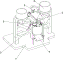
Fig. 1 is a schematic perspective view of a first perspective structure according to the present invention.
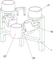
Fig. 2 is a perspective view of a second perspective structure according to the present invention.
Fig. 3 is a schematic sectional perspective view of the pushing mechanism of the present invention.
Fig. 4 is a schematic sectional perspective view of the stirring mechanism of the present invention.
Fig. 5 is a schematic perspective view of the feeding mechanism of the present invention.
Fig. 6 is a schematic perspective view of the material control mechanism of the present invention.
Fig. 7 is a schematic perspective view of the dust removing mechanism of the present invention.
Fig. 8 is a schematic perspective view of the stirring mechanism of the present invention.
The parts are labeled as follows: 1. the device comprises a bottom plate, 2, a material pushing mechanism, 21, a servo motor, 22, a first rotating shaft, 23, a stirring barrel, 24, a second rotating shaft, 25, a transmission component, 26, a push plate, 27, a first bevel gear set, 3, a stirring mechanism, 31, a fixing frame, 32, an inner ring gear, 33, a third rotating shaft, 34, a straight gear, 35, a stirring sheet, 4, a feeding mechanism, 41, a material containing barrel, 42, a material guiding box, 43, a material guiding pipe, 5, a material control mechanism, 51, a fixing block, 52, a material baffle plate, 53, a telescopic component, 54, a pushing block, 55, a lug, 6, a dust removal mechanism, 61, a fourth rotating shaft, 62, a fan, 63, a second bevel gear set, 64, a third bevel gear set, 7, a material mixing mechanism, 71, a sliding rod, 72, a material guiding plate, 73, a spring, 74, a connecting block, 75 and a.
Detailed Description
The technical solutions in the embodiments of the present invention will be clearly and completely described below, and it is obvious that the described embodiments are only a part of the embodiments of the present invention, and not all embodiments. All other embodiments, which can be derived by a person skilled in the art from the embodiments given herein without making any creative effort, shall fall within the protection scope of the present invention.
Example 1
A uniform mixing and dedusting device for biomass energy particle production is shown in figures 1-2 and comprises a bottom plate 1, a material pushing mechanism 2 and a stirring mechanism 3, wherein the bottom plate 1 is connected with the material pushing mechanism 2, and the stirring mechanism 3 is arranged on the material pushing mechanism 2.
When people need to mix the particles, the two different particles are poured into the material pushing mechanism 2, then the material pushing mechanism 2 is started, the stirring mechanism 3 continuously stirs the particles, the particles can be mixed, and the material pushing mechanism 2 is closed after the material mixing is completed.
Example 2
On the basis of embodiment 1, as shown in fig. 3-4, the pushing mechanism 2 includes a servo motor 21, a first rotating shaft 22, a stirring barrel 23, a second rotating shaft 24, a transmission assembly 25, a pushing plate 26 and a first bevel gear set 27, the servo motor 21 is connected to the middle of the rear side of the bottom plate 1, the first rotating shaft 22 is rotatably connected to the middle of the rear side of the bottom plate 1, the first rotating shaft 22 is located at the front side of the servo motor 21, the stirring barrel 23 is connected to the middle of the front side of the bottom plate 1, the second rotating shaft 24 is rotatably connected to the middle of the stirring barrel 23, the transmission assembly 25 is connected between the second rotating shaft 24 and the first rotating shaft 22, the pushing plate 26 is uniformly connected to the lower portion of the second rotating shaft 24, the pushing plate 26 is connected to the stirring mechanism 3, and the first bevel.
When people need carry out the compounding with the granule, pour into agitator 23 with two kinds of different granules earlier in, start servo motor 21, servo motor 21 output shaft rotates and drives first bevel gear group 27, first pivot 22, drive assembly 25, second pivot 24 and push pedal 26 and rotate, and then drive rabbling mechanism 3 and stir the granule, flow out from agitator 23 bottom after the stirring, people can collect it, it can to close servo motor 21 afterwards.
The stirring mechanism 3 comprises a fixed frame 31, an inner ring gear 32, a third rotating shaft 33, a straight gear 34 and stirring pieces 35, the fixed frame 31 is arranged between the tops of the push plates 26, three sides of the fixed frame 31 are rotatably connected with the third rotating shaft 33, the straight gear 34 is arranged on the upper portion of the third rotating shaft 33, the inner wall of the upper portion of the stirring barrel 23 is connected with the inner ring gear 32, the inner ring gear 32 is meshed with the straight gear 34, and the lower portion of the third rotating shaft 33 is connected with the stirring pieces 35.
The push plate 26 rotates to drive the fixed frame 31, the third rotating shaft 33 and the straight gear 34 to rotate, and under the action of the inner ring gear 32, the straight gear 34 and the third rotating shaft 33 are driven to rotate continuously, so that the stirring sheet 35 is driven to stir particles continuously.
Example 3
On the basis of the embodiment 2, as shown in fig. 5 to 8, the stirring device further comprises a feeding mechanism 4, wherein the feeding mechanism 4 comprises material containing tubes 41, material guiding boxes 42 and material guiding pipes 43, the material containing tubes 41 are connected to the upper portions of the left and right sides of the front portion of the bottom plate 1, the material guiding boxes 42 are connected to the lower portions of the left and right sides of the front portion of the bottom plate 1, the material guiding boxes 42 are located at the bottoms of the material containing tubes 41, and the material guiding pipes 43 are connected between the material guiding boxes 42 and the stirring barrel 23.
When people need to mix the particles, two different particles are poured into the material containing barrel 41 respectively, and the particles flow into the stirring barrel 23 through the material guiding box 42 and the material guiding pipe 43 respectively to be stirred.
Still including accuse material mechanism 5, accuse material mechanism 5 is including fixed block 51, striker plate 52, flexible subassembly 53, ejector pad 54 and lug 55, the agitator 23 left and right sides all is connected with fixed block 51, all sliding connection has flexible subassembly 53 on the fixed block 51, the equal sliding connection of passage 43 has striker plate 52, striker plate 52 is connected with flexible subassembly 53, flexible subassembly 53 top all is connected with ejector pad 54, spur gear 34 top all is connected with lug 55, lug 55 and ejector pad 54 contact cooperation.
Still including dust removal mechanism 6, dust removal mechanism 6 is including fourth pivot 61, fan 62, second bevel gear group 63 and third bevel gear group 64, the equal rotary type in 1 rear portion left and right sides of bottom plate is connected with fourth pivot 61, fourth pivot 61 front side all is connected with fan 62, the equal rotary type in 1 rear portion left and right sides of bottom plate is connected with the fifth pivot, the fifth pivot is located fourth pivot 61 inboardly, all be connected with second bevel gear group 63 between fifth pivot rear side and the fourth pivot 61 rear side, be connected with third bevel gear group 64 between first pivot 22 upper portion and the fifth pivot front side.
The rotation of the first rotating shaft 22 drives the third bevel gear set 64, the fifth rotating shaft, the second bevel gear set 63, the fourth rotating shaft 61 and the fan 62 to rotate continuously, so that impurities in the particles are blown away.
Still including mixing material mechanism 7, mix material mechanism 7 including slide bar 71, stock guide 72, spring 73, connecting block 74 and wedge 75, sliding type connection has slide bar 71 in the middle of the bottom plate 1 front side, be equipped with stock guide 72 on the slide bar 71, stock guide 72 is located agitator 23 downside, all be equipped with spring 73 between stock guide 72 left and right sides and the bottom plate 1, spring 73 all overlaps in the slide bar 71 outside, the stock guide 72 right side is connected with connecting block 74, connecting block 74 upper portion is connected with wedge 75, wedge 75 and lug 55 contact cooperation.
When the wedge block 75 contacts the projection 55, the connecting block 74 and the wedge block 75 are driven to move rightwards, so that the material guide plate 72 moves rightwards, the left spring 73 is stretched, the right spring 73 is compressed, when the wedge block 75 is separated from the projection 55, the connecting block 74, the wedge block 75 and the material guide plate 72 are driven to move leftwards and reset under the action of the spring 73, and thus, the stirred particles flow onto the material guide plate 72 through the stirring barrel 23 to shake.
While the disclosure has been shown and described with reference to certain exemplary embodiments thereof, it will be understood by those skilled in the art that various changes in form and details may be made therein without departing from the spirit and scope of the disclosure as defined by the appended claims and their equivalents. Accordingly, the scope of the present disclosure should not be limited to the above-described embodiments, but should be defined not only by the appended claims, but also by equivalents thereof.
Claims (8)
1. The utility model provides a production of biomass energy granule is with even compounding dust collecting equipment, characterized by, including:
the device comprises a bottom plate (1) and a material pushing mechanism (2), wherein the bottom plate (1) is connected with the material pushing mechanism (2);
the stirring mechanism (3) is arranged on the material pushing mechanism (2).
2. The uniform mixing and dedusting equipment for the production of the biomass energy particles as claimed in claim 1, wherein the material pushing mechanism (2) comprises:
one side of the bottom plate (1) is connected with the servo motor (21);
the first rotating shaft (22) is rotatably connected to one side of the bottom plate (1), and the first rotating shaft (22) is located on one side of the servo motor (21);
the stirring barrel (23) is connected with one side of the bottom plate (1);
the second rotating shaft (24) is rotatably connected with the stirring barrel (23);
the transmission component (25) is connected between the second rotating shaft (24) and the first rotating shaft (22);
the lower part of the second rotating shaft (24) is uniformly connected with the push plate (26), and the push plate (26) is connected with the stirring mechanism (3);
a first bevel gear set (27) is arranged between the output shaft of the servo motor (21) and the first rotating shaft (22).
3. The uniform mixing and dedusting device for the production of the biomass energy particles as claimed in claim 2, wherein the stirring mechanism (3) comprises:
a fixing frame (31), wherein the fixing frame (31) is arranged between the tops of the push plates (26);
three sides of the fixed frame (31) are rotatably connected with the third rotating shaft (33);
the straight gear (34) and the third rotating shaft (33) are both provided with the straight gear (34);
the inner wall of the stirring barrel (23) is connected with an inner ring gear (32), and the inner ring gear (32) is meshed with a straight gear (34);
the lower parts of the stirring pieces (35) and the third rotating shaft (33) are connected with the stirring pieces (35).
4. The uniform mixing and dedusting equipment for the production of the biomass energy particles as claimed in claim 3, which is characterized by further comprising a feeding mechanism (4), wherein the feeding mechanism (4) comprises:
the two sides of the bottom plate (1) are connected with the material containing barrels (41);
the two sides of the bottom plate (1) are both connected with the material guiding boxes (42), and the material guiding boxes (42) are positioned at the bottoms of the material containing tubes (41);
the material guide pipes (43) are connected between the material guide box (42) and the stirring barrel (23).
5. The uniform mixing and dedusting equipment for the production of the biomass energy particles as claimed in claim 4, which is characterized by further comprising a material control mechanism (5), wherein the material control mechanism (5) comprises:
the two sides of the stirring barrel (23) are connected with the fixed blocks (51);
the fixed blocks (51) are connected with the telescopic components (53) in a sliding manner;
the material guide pipes (43) are connected with material guide plates (52) in a sliding mode, and the material guide plates (52) are connected with telescopic assemblies (53);
the top of the push block (54) and the top of the telescopic component (53) are both connected with the push block (54);
the tops of the convex blocks (55) and the straight gears (34) are connected with the convex blocks (55), and the convex blocks (55) are in contact fit with the push blocks (54).
6. The uniform mixing and dedusting device for the production of the biomass energy particles as claimed in claim 5, which is characterized by further comprising a dedusting mechanism (6), wherein the dedusting mechanism (6) comprises:
the two sides of the bottom plate (1) are rotatably connected with the fourth rotating shaft (61);
the fans (62) are connected to the front sides of the fourth rotating shafts (61);
the two sides of the bottom plate (1) are rotatably connected with fifth rotating shafts, the fifth rotating shafts are located on the inner sides of the fourth rotating shafts (61), and the second bevel gear sets (63) are connected between the fifth rotating shafts and the fourth rotating shafts (61);
and a third bevel gear set (64) is connected between the first rotating shaft (22) and the fifth rotating shaft.
7. The uniform mixing and dedusting device for the production of the biomass energy particles as claimed in claim 6, which is characterized by further comprising a material mixing mechanism (7), wherein the material mixing mechanism (7) comprises:
the bottom plate (1) is connected with a sliding rod (71) in a sliding manner;
the material guide plate (72) is arranged on the sliding rod (71), and the material guide plate (72) is positioned on the lower side of the stirring barrel (23);
springs (73), the springs (73) are arranged between the two sides of the material guide plate (72) and the bottom plate (1), and the springs (73) are sleeved on the outer sides of the sliding rods (71);
one side of the material guide plate (72) is connected with the connecting block (74);
the wedge block (75) is connected to the connecting block (74), and the wedge block (75) is in contact fit with the projection (55).
8. The uniform mixing and dedusting equipment for biomass energy particle production as recited in claim 6, characterized in that the rotation speed of the fan (62) is 1800 rpm.
Priority Applications (1)
| Application Number | Priority Date | Filing Date | Title |
|---|---|---|---|
| CN202011108650.XA CN112452186A (en) | 2020-10-16 | 2020-10-16 | Biomass energy particle production is with even compounding dust collecting equipment |
Applications Claiming Priority (1)
| Application Number | Priority Date | Filing Date | Title |
|---|---|---|---|
| CN202011108650.XA CN112452186A (en) | 2020-10-16 | 2020-10-16 | Biomass energy particle production is with even compounding dust collecting equipment |
Publications (1)
| Publication Number | Publication Date |
|---|---|
| CN112452186A true CN112452186A (en) | 2021-03-09 |
Family
ID=74833840
Family Applications (1)
| Application Number | Title | Priority Date | Filing Date |
|---|---|---|---|
| CN202011108650.XA Pending CN112452186A (en) | 2020-10-16 | 2020-10-16 | Biomass energy particle production is with even compounding dust collecting equipment |
Country Status (1)
| Country | Link |
|---|---|
| CN (1) | CN112452186A (en) |
Cited By (1)
| Publication number | Priority date | Publication date | Assignee | Title |
|---|---|---|---|---|
| CN113926771A (en) * | 2021-09-24 | 2022-01-14 | 郭武平 | Cleaning equipment for new amorphous alloy material particles |
-
2020
- 2020-10-16 CN CN202011108650.XA patent/CN112452186A/en active Pending
Cited By (1)
| Publication number | Priority date | Publication date | Assignee | Title |
|---|---|---|---|---|
| CN113926771A (en) * | 2021-09-24 | 2022-01-14 | 郭武平 | Cleaning equipment for new amorphous alloy material particles |
Similar Documents
| Publication | Publication Date | Title |
|---|---|---|
| CN107551854A (en) | A kind of carbon dust mixing arrangement | |
| CN208574938U (en) | PVC granular material in medical use filter device | |
| CN112452186A (en) | Biomass energy particle production is with even compounding dust collecting equipment | |
| CN117341184B (en) | Film blowing device of film blowing machine | |
| CN114877641A (en) | Metal powder preheating and drying device for additive manufacturing | |
| CN112779124B (en) | Modified starch production device utilizing enzyme | |
| JP2001079377A (en) | Multishaft mixer | |
| CN207357538U (en) | Abrasive grains separator is used in a kind of shoddye heat preserving agent production | |
| CN105413583B (en) | A kind of efficiently granulator and its method of work | |
| CN111451438B (en) | Sand mixing device for casting machine | |
| CN210252134U (en) | Mixed type feed additive production is with smashing mixing arrangement | |
| CN114272972A (en) | Quick sub-packaging equipment of rice | |
| CN112845062A (en) | Energy-conserving formula industrial material screening dust collector | |
| CN213314842U (en) | Granule mixing and pressing equipment for producing traditional Chinese medicine granular tea | |
| CN220968771U (en) | Feeding filtering structure of electrolytic degreasing agent raw material mixer | |
| CN220919454U (en) | Raw material preparation system device for ferrosilicon production | |
| CN215463552U (en) | Convenient reinforced industrial chemicals agitating unit | |
| CN115093109B (en) | Automatic fusion casting device for glass fiber waste | |
| CN216654400U (en) | Proportioning device for chemical raw materials | |
| CN112403612B (en) | Leftover material crushing device for production of spliced blackboard | |
| CN218531313U (en) | Device convenient to clearance granulator magnetic sheet | |
| CN213680827U (en) | Device for recycling acid-dissolving slag to reproduce rare earth | |
| CN215882166U (en) | Refining mixing arrangement is used in production of plastics modified particles | |
| CN219464027U (en) | Stone material vibration feeder | |
| CN217568443U (en) | Homogenizing device for micro silicon powder |
Legal Events
| Date | Code | Title | Description |
|---|---|---|---|
| PB01 | Publication | ||
| PB01 | Publication | ||
| SE01 | Entry into force of request for substantive examination | ||
| SE01 | Entry into force of request for substantive examination |