CN112413355A - Lifting device of electronic equipment - Google Patents
Lifting device of electronic equipment Download PDFInfo
- Publication number
- CN112413355A CN112413355A CN202110093983.8A CN202110093983A CN112413355A CN 112413355 A CN112413355 A CN 112413355A CN 202110093983 A CN202110093983 A CN 202110093983A CN 112413355 A CN112413355 A CN 112413355A
- Authority
- CN
- China
- Prior art keywords
- chain
- bending
- bin
- arc
- lifting device
- Prior art date
- Legal status (The legal status is an assumption and is not a legal conclusion. Google has not performed a legal analysis and makes no representation as to the accuracy of the status listed.)
- Granted
Links
Images


Classifications
-
- F—MECHANICAL ENGINEERING; LIGHTING; HEATING; WEAPONS; BLASTING
- F16—ENGINEERING ELEMENTS AND UNITS; GENERAL MEASURES FOR PRODUCING AND MAINTAINING EFFECTIVE FUNCTIONING OF MACHINES OR INSTALLATIONS; THERMAL INSULATION IN GENERAL
- F16M—FRAMES, CASINGS OR BEDS OF ENGINES, MACHINES OR APPARATUS, NOT SPECIFIC TO ENGINES, MACHINES OR APPARATUS PROVIDED FOR ELSEWHERE; STANDS; SUPPORTS
- F16M11/00—Stands or trestles as supports for apparatus or articles placed thereon Stands for scientific apparatus such as gravitational force meters
- F16M11/20—Undercarriages with or without wheels
- F16M11/24—Undercarriages with or without wheels changeable in height or length of legs, also for transport only, e.g. by means of tubes screwed into each other
- F16M11/26—Undercarriages with or without wheels changeable in height or length of legs, also for transport only, e.g. by means of tubes screwed into each other by telescoping, with or without folding
- F16M11/28—Undercarriages for supports with one single telescoping pillar
-
- F—MECHANICAL ENGINEERING; LIGHTING; HEATING; WEAPONS; BLASTING
- F16—ENGINEERING ELEMENTS AND UNITS; GENERAL MEASURES FOR PRODUCING AND MAINTAINING EFFECTIVE FUNCTIONING OF MACHINES OR INSTALLATIONS; THERMAL INSULATION IN GENERAL
- F16M—FRAMES, CASINGS OR BEDS OF ENGINES, MACHINES OR APPARATUS, NOT SPECIFIC TO ENGINES, MACHINES OR APPARATUS PROVIDED FOR ELSEWHERE; STANDS; SUPPORTS
- F16M11/00—Stands or trestles as supports for apparatus or articles placed thereon Stands for scientific apparatus such as gravitational force meters
- F16M11/02—Heads
- F16M11/04—Means for attachment of apparatus; Means allowing adjustment of the apparatus relatively to the stand
- F16M11/043—Allowing translations
- F16M11/046—Allowing translations adapted to upward-downward translation movement
-
- G—PHYSICS
- G03—PHOTOGRAPHY; CINEMATOGRAPHY; ANALOGOUS TECHNIQUES USING WAVES OTHER THAN OPTICAL WAVES; ELECTROGRAPHY; HOLOGRAPHY
- G03B—APPARATUS OR ARRANGEMENTS FOR TAKING PHOTOGRAPHS OR FOR PROJECTING OR VIEWING THEM; APPARATUS OR ARRANGEMENTS EMPLOYING ANALOGOUS TECHNIQUES USING WAVES OTHER THAN OPTICAL WAVES; ACCESSORIES THEREFOR
- G03B21/00—Projectors or projection-type viewers; Accessories therefor
- G03B21/54—Accessories
Abstract
The invention relates to a lifting device of electronic equipment, which comprises a mounting rack, a chain bin, a chain, a transmission gear and a driving motor, wherein the chain bin is arranged on the mounting rack; the chain comprises a plurality of chain sheets and a plurality of bending chain sheets; the adjacent chain sheets are connected through a bending chain sheet, and the chain sheet and the bending chain sheet form rotating connection through a rotating shaft; the driving motor is fixedly arranged on the mounting frame, and an output shaft of the driving motor is in transmission connection with the transmission gear; a plurality of driving bodies are arranged on one side of the chain corresponding to the transmission gear along the sliding direction of the chain; the chain bin is fixedly arranged on the mounting frame, and a containing bin chamber for the chain to slide out or in when the driving body of the chain is shifted by the transmission gear is arranged in the chain bin; one end of the chain is always positioned in the storage bin, and the other end of the chain extends out of the storage bin to form a connecting end; one end of the chain extending out of the storage chamber is vertically downward under the action of gravity. The lifting device is ingenious in structural design, can achieve a longer lifting stroke in a limited space, is stable and reliable in lifting, and can effectively reduce the problem of lifting and shaking.
Description
Technical Field
The present invention relates to a device for driving an electronic device to ascend and descend, and more particularly, to an ascending and descending device for an electronic device.
Background
Lifting devices are widely used in many fields, such as lifting of projectors, lifting of televisions, and other electronic devices that need to fulfill lifting requirements. The existing lifting devices generally comprise an electric telescopic rod (or a lifting mechanism based on the principle of the electric telescopic rod), a connecting rod lifting mechanism and the like, and the lifting devices have larger overall structures in order to ensure lifting strokes. If the installation space in the vertical direction is limited, the conventional lifting device is often troublesome to install.
For example, when the projector is installed, if the installation position is not provided with a ceiling, the lifting device is exposed inevitably, and the overall attractiveness of the existing lifting device is not enough after the lifting device is installed and used. If there is a ceiling at the installation position, but the ceiling has a limited hanging height, there is a problem that the installation cannot be completely hidden.
Disclosure of Invention
The invention aims to provide a lifting device of electronic equipment, which is ingenious in structural design, can achieve a longer lifting stroke in a limited space, is stable and reliable in lifting and can effectively reduce the problem of lifting and shaking.
The technical scheme for realizing the purpose of the invention is as follows: the invention comprises a mounting rack, a chain bin, a chain, a transmission gear and a driving motor; the chain comprises a plurality of chain sheets and a plurality of bending chain sheets; the adjacent chain sheets are connected through a bending chain sheet, and the chain sheet and the bending chain sheet form rotating connection through a rotating shaft; the driving motor is fixedly arranged on the mounting frame, and an output shaft of the driving motor is in transmission connection with the transmission gear; a plurality of driving bodies are arranged on one side of the chain corresponding to the transmission gear along the sliding direction of the chain; the chain bin is fixedly arranged on the mounting frame, and a storage bin chamber for allowing the chain to slide out or in when the driving body of the chain is shifted by the transmission gear is arranged in the chain bin; one end of the chain is always positioned in the storage bin, and the other end of the chain extends out of the storage bin to form a connecting end; one end of the chain extending out of the storage chamber is vertically downward under the action of gravity.
The chain is provided with a threading groove for threading.
A telescopic shell is fixedly arranged at an outlet of the storage chamber; the telescopic shell comprises a plurality of shells which are sequentially sleeved in a sliding mode to form a telescopic structure; the casing at the uppermost end is fixedly connected with the chain bin or the mounting rack; the connecting end of the chain penetrates into the telescopic shell and is fixedly connected with the casing at the lowest end.
The storage chamber is in a curved shape for the chain to be stored in.
Preferably, the storage chamber is curved in one direction and the chain can be stored therein in a curved shape. Preferably, the storage chamber may be designed to have a curved shape with three bends. Of course, more bends can be designed as long as the chain can be bent. Meanwhile, the receiving chamber can be designed into a vortex shape.
One side of the chain sheet is provided with a first arc-shaped groove, and the other side of the chain sheet is provided with a first arc-shaped bulge; the first arc-shaped bulge of the next chain sheet is correspondingly in limit fit with the first arc-shaped groove of the previous chain sheet, and when the adjacent chain sheets are positioned on the same straight line, the adjacent chain sheets can not relatively rotate towards the opposite direction of the unidirectional bending under the limit fit of the first arc-shaped bulge and the first arc-shaped groove;
and/or one side of the bending chain piece is provided with a second arc-shaped groove, and the other side of the bending chain piece is provided with a second arc-shaped bulge; the second arc-shaped protrusion of the next bending chain piece and the second arc-shaped groove of the last bending chain piece correspond to the limiting fit, and when the adjacent bending chain pieces are located on the same straight line, the adjacent bending chain pieces can not rotate relatively to the opposite direction of the one-way bending under the limiting fit of the second arc-shaped protrusion and the second arc-shaped groove.
As an optimized design, the rotating shaft is positioned at one end of the transmission gear to form a driving body.
The two chains simultaneously penetrate through the chain sheets corresponding to the two chains and the bent chain sheet through the rotating shaft to form synchronous bending;
a wire covering plate is arranged on the bending chain piece on one chain or the two symmetrical bending chain pieces are connected through the wire covering plate; threading grooves are formed between the two chains and between the thread covering plate and the rotating shaft.
The mounting rack is a box body; the box body is provided with an opening for the telescopic shell to extend out and retract; the chain bin, the driving motor and the transmission gear are all arranged in the box body. The box body can be designed into a box body with a box cover, thereby being convenient for later maintenance.
A pin shaft is arranged at one end of the chain, which is positioned in the storage chamber; the chain bin is provided with a limiting groove extending along the extension direction of the storage bin; the pin shaft is arranged in the limiting groove in a sliding mode.
The chain bin comprises two substrates which are symmetrically arranged; a partition plate is arranged between the two substrates; the partition plate partitions the space between the two substrates to form a storage chamber; limiting grooves are formed in the two substrates along the extending direction of the partition plates; two ends of the pin shaft are respectively arranged in the limiting grooves of the two substrates in a sliding manner.
A guide part for guiding the chain to vertically extend downwards is arranged at an outlet of the chain storage chamber; the guide part comprises a first guide plate and a second guide plate which are oppositely arranged and form a channel extending vertically downwards between the first guide plate and the second guide plate; the first guide plate is connected with the lower end of the outlet; the second guide plate is connected with the upper end of the outlet.
The second guide plate is in a guide arc shape with the joint of the outlet of the storage bin.
A sealing plate is fixedly arranged on the casing at the lowest end of the telescopic shell and below the electronic equipment; when the telescopic shell is folded into the box body, the opening is sealed by the sealing plate.
The invention has the positive effects that: (1) the driving motor drives the transmission gear, the transmission gear drives the chain to slide, lifting is realized through the extending formation of the chain, and meanwhile, the chain is in flexible connection, so that the occupied space of the chain is small when the chain is stored, and the size of the lifting device is greatly reduced.
(2) The wire can be better accommodated through the threading groove, so that the problem that the wire interferes with lifting can be avoided, and the wire can be well protected; meanwhile, the electric wire can be hidden, and the attractiveness is improved.
(3) According to the invention, the chain can be effectively hidden through the telescopic shell, the attractiveness is improved, and the telescopic shell and the electronic equipment are easier to connect and mount.
(4) The distribution shape of the storage bin can further reduce the space occupation when the chain is stored, thereby further reducing the whole volume.
(5) According to the invention, through the limit matching of the first arc-shaped groove and the first arc-shaped protrusion and/or the limit matching of the second arc-shaped groove and the second arc-shaped protrusion, the chain sheet and the chain sheet can not rotate excessively in a relative manner in a vertical state (namely, during lifting), so that the lifting stability is ensured.
(6) One end of the rotating shaft is directly used as a driving body, so that the effect of multiple purposes can be achieved, and the production cost is reduced.
(7) According to the invention, the two chains and the wire covering plate can form the wire threading groove, and the electric wire can be well protected and hidden.
(8) The mounting rack is designed into a box body, so that better integrity and attractiveness can be realized, and a part protection effect can be realized.
(9) The invention can effectively limit the telescopic stroke of the chain through the limit groove and the pin shaft, and prevent the chain from separating from the chain bin.
(10) The guide part is favorable for guiding the chain to vertically downwards, and the guide arc-shaped design is more convenient for bending and guiding the chain, so that the chain is further ensured to vertically downwards, and a certain downward thrust is attached, so that the stability of the chain is further improved.
(11) According to the invention, through the sealing plate, the dustproof and protection effects on the electronic equipment after the telescopic shell is folded can be improved, and the integrity and the attractiveness of the device can be improved.
Drawings
In order that the present disclosure may be more readily and clearly understood, reference is now made to the following detailed description of the present disclosure taken in conjunction with the accompanying drawings, in which
FIG. 1 is a schematic structural view of the present invention;
FIG. 2 is a schematic view of the interior of the mount of the present invention;
FIG. 3 is a schematic view of the engagement of the driving gear and the driving body according to the present invention;
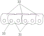
FIG. 4 is a schematic view of the structure of the chain of the present invention;
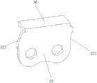
FIG. 5 is a schematic view of the structure of the chain sheet of the present invention;
FIG. 6 is a schematic structural view of a bending link according to the present invention;
FIG. 7 is a schematic view of the relative rotation of adjacent links in the present invention;
FIG. 8 is a schematic view of the present invention showing the adjacent links in a straight line;
FIG. 9 is a schematic view of the fit between adjacent housings on the telescoping shell of the present invention;
FIG. 10 is a schematic view of the chain magazine of the present invention;
fig. 11 is an exploded view of the chain magazine of the present invention.
Detailed Description
Referring to fig. 1 and 2, the invention comprises a mounting rack 1, a chain bin 2, a chain 3, a transmission gear 4, a driving motor 5 and a telescopic shell 6; the mounting rack 1 is a box body with a box cover; the lower end face of the box body is provided with an opening 11; a chain bin 2, a transmission gear 4 and a driving motor 5 are fixedly arranged in the box body.
Fig. 4 to 6 show two symmetrically arranged chains 3, wherein the chains 3 comprise a plurality of chain links 31 and a plurality of bending chain links 32; the adjacent links 31 are connected by a bent link 32; after the two chains 3 simultaneously pass through the chain pieces 31 and the bent chain pieces 32 corresponding to the two chains 3 through the rotating shaft 33, synchronous bending is formed;
a wire covering plate 36 is arranged on the bending chain piece 32 on one chain 3; threading grooves 35 are formed between the two chains 3 and between the thread covering plate 36 and the rotating shaft 33.
Referring to fig. 1 to 4, the driving motor 5 is fixedly mounted on the mounting frame 1, an output shaft of the driving motor 5 is in transmission connection with an input end of a reduction gear box, and an output end of the reduction gear box is in transmission connection with the transmission gear 4; one end of each rotating shaft 33 corresponding to the transmission gear 4 forms a driving body 34; the chain bin 2 is fixedly arranged on the mounting frame 1, and a storage bin chamber 21 for allowing the chain 3 to slide out or in when a driving body 34 of the chain 3 is shifted by the transmission gear 4 is arranged in the chain bin 2; one end of the chain 3 is always positioned in the storage chamber 21, and the other end of the chain 3 extends out of the storage chamber 21 to form a connecting end; one end of the chain 3 extending out of the storage chamber 21 is vertically downward by gravity. The transmission gear 4 extends into the chain bin 2 and is correspondingly matched with the driving body 34.
See fig. 2, the outlet of the receiving chamber 21 is directed vertically downward; a telescopic shell 6 is fixedly arranged at the outlet of the containing chamber 21; the telescopic shell 6 comprises a plurality of shells which are sequentially sleeved in a sliding manner and form a telescopic structure; the shell at the uppermost end is fixedly connected with the chain bin 2; the connecting end of the chain 3 penetrates into the telescopic shell 6 and is fixedly connected with the casing at the lowest end.
See fig. 9, in which the shells are sequentially enlarged from top to bottom and are sequentially nested; the upper end of each shell is provided with a first limiting step 61 which shrinks towards the inner cavity, and the lower end of each shell is provided with a second limiting step 62 which extends outwards; adjacent shells are sleeved and form a sliding fit, and meanwhile, a sliding limit is formed by the first limit step 61 and the second limit step 62. Just because of the sliding limit, the telescopic shell 6 can be stretched.
The storage chamber 21 is bent in a single direction and can be used for bending and storing the chain, and the storage chamber 21 is bent for three times so as to improve the lifting stroke in a limited installation space.
Referring to fig. 5 to 8, one side of the chain sheet 31 is provided with a first arc-shaped groove 311, and the other side of the chain sheet 31 is provided with a first arc-shaped protrusion 312; the first arc-shaped protrusion 312 of the next chain piece 31 is correspondingly in limit fit with the first arc-shaped groove 311 of the previous chain piece 31, and when the adjacent chain pieces 31 are positioned on the same straight line, the adjacent chain pieces 31 can not relatively rotate in the opposite direction of the unidirectional bending under the limit fit of the first arc-shaped protrusion 312 and the first arc-shaped groove 311;
one side of the bending chain sheet 32 is provided with a second arc-shaped groove 321, and the other side of the bending chain sheet 32 is provided with a second arc-shaped protrusion 322; the second arc-shaped protrusion 322 of the next bending chain piece 32 corresponds to the second arc-shaped groove 321 of the previous bending chain piece 32 in a limiting fit manner, and when the adjacent bending chain pieces 32 are located on the same straight line, the adjacent bending chain pieces 32 can not rotate relatively to the opposite direction of the unidirectional bending under the limiting fit of the second arc-shaped protrusion 322 and the second arc-shaped groove 321.
Referring to fig. 4, a pin 7 is arranged at one end of the chain 3, which is located in the storage chamber 21; the chain bin 2 is provided with a limiting groove 22 extending along the extension direction of the storage bin 21; the pin shaft 7 is arranged in the limiting groove 22 in a sliding manner.
Referring to fig. 10 and 11, the chain magazine 2 includes two base plates 23 symmetrically disposed; a partition plate 24 is arranged between the two substrates 23; the partition plate 24 partitions the space between the two substrates 23 to form a storage chamber 21; the two substrates 23 are provided with limit grooves 22 along the extension direction of the partition plate 24; two ends of the pin shaft 7 are respectively arranged in the limiting grooves 22 of the two substrates 23 in a sliding manner.
A guide part 25 for guiding the chain 3 to vertically extend downwards is arranged at the outlet of the storage chamber 21 on the chain bin 2; the guide part 25 includes a first guide plate 251 and a second guide plate 252 which are oppositely disposed and between which a passage extending vertically downward is formed; the first guide plate 251 is engaged with the lower end of the outlet; the second guide plate 252 is engaged with the upper end of the outlet.
The junction 26 of the second guide plate 252 and the outlet of the receiving chamber 21 is in a guide arc shape.
Referring to fig. 1, a sealing plate 8 is fixedly arranged on the casing at the lowest end of the telescopic casing 6 and below the electronic device; when the telescopic shell 6 is folded into the box body, the opening 11 is sealed by the sealing plate 8.
The action process of the invention is as follows:
a descending state: the driving motor 5 drives the transmission gear 4 to rotate forwards through the reduction gear box, the transmission gear 4 drives the driving body 34 and drives the chain 3 to slide out of the storage bin 21 of the chain bin 2, and the chain 3 naturally and vertically falls under the guiding of a vertically downward outlet of the storage bin 21 and the action of gravity; due to the automatic connection characteristic of the chain 3, the shells of the telescopic shells 6 can be pushed to be opened in sequence, so that the telescopic shells 6 can be seen to descend from the opening of the box body to be opened.
A rising state: the driving motor 5 drives the transmission gear 4 to rotate reversely through the reduction gear box, the transmission gear 4 drives the driving body 34 and drives the chain 3 to slide into the storage bin 21 of the chain bin 2, the chain 3 drives the lowest shell of the telescopic shell 6 to ascend, and the telescopic shell 6 is seen to be folded upwards until the telescopic shell is folded into the opening due to the fact that the shells are in sliding sleeving.
The above-mentioned embodiments are intended to illustrate the objects, technical solutions and advantages of the present invention in further detail, and it should be understood that the above-mentioned embodiments are only exemplary embodiments of the present invention, and are not intended to limit the present invention, and any modifications, equivalents, improvements and the like made within the spirit and principle of the present invention should be included in the protection scope of the present invention.
Claims (13)
1. Electronic equipment's elevating gear, its characterized in that: comprises a mounting rack (1), a chain bin (2), a chain (3), a transmission gear (4) and a driving motor (5); the chain (3) comprises a plurality of chain pieces (31) and a plurality of bending chain pieces (32); the adjacent chain sheets (31) are connected through a bending chain sheet (32), and the chain sheets (31) and the bending chain sheet (32) form rotating connection through a rotating shaft (33); the driving motor (5) is fixedly arranged on the mounting rack (1), and an output shaft of the driving motor (5) is in transmission connection with the transmission gear (4); a plurality of driving bodies (34) are arranged on one side of the chain (3) corresponding to the transmission gear (4) along the sliding direction of the chain; the chain bin (2) is fixedly arranged on the mounting frame (1), and a containing bin chamber (21) for allowing the chain (3) to slide out or in when a driving body (34) of the chain is shifted by the transmission gear (4) is arranged in the chain bin (2); one end of the chain (3) is always positioned in the storage chamber (21), and the other end of the chain (3) extends out of the storage chamber (21) to form a connecting end; one end of the chain (3) extending out of the storage chamber (21) is vertically downward under the action of gravity.
2. The lifting device of an electronic apparatus according to claim 1, characterized in that: and a threading groove (35) for threading is arranged on the chain (3).
3. The lifting device of an electronic apparatus according to claim 1, characterized in that: a telescopic shell (6) is fixedly arranged at an outlet of the storage chamber (21); the telescopic shell (6) comprises a plurality of shells which are sequentially sleeved in a sliding mode and form a telescopic structure; the uppermost shell is fixedly connected with the chain bin (2) or the mounting rack (1); the connecting end of the chain (3) penetrates into the telescopic shell (6) and is fixedly connected with the casing at the lowest end.
4. The lifting device of an electronic apparatus according to claim 1, 2 or 3, wherein: the containing chamber (21) is in a curved shape for containing the chain (3) in a curved manner.
5. The lifting device of an electronic apparatus according to claim 4, wherein: the accommodating chamber (21) is bent in a single direction and can accommodate the chain in a bent manner;
one side of the chain sheet (31) is provided with a first arc-shaped groove (311), and the other side of the chain sheet (31) is provided with a first arc-shaped bulge (312); the first arc-shaped protrusion (312) of the next chain piece (31) is correspondingly in limit fit with the first arc-shaped groove (311) of the previous chain piece (31), and when the adjacent chain pieces (31) are positioned on the same straight line, the adjacent chain pieces (31) can not rotate relatively in the opposite direction of unidirectional bending under the limit fit of the first arc-shaped protrusion (312) and the first arc-shaped groove (311);
and/or one side of the bending chain piece (32) is provided with a second arc-shaped groove (321), and the other side of the bending chain piece (32) is provided with a second arc-shaped bulge (322); the second arc-shaped protrusion (322) of the next bending chain piece (32) and the second arc-shaped groove (321) of the previous bending chain piece (32) correspond to limit matching, and when the adjacent bending chain pieces (32) are located on the same straight line, the adjacent bending chain pieces (32) can not rotate relatively to the opposite direction of the unidirectional bending under the limit matching of the second arc-shaped protrusion (322) and the second arc-shaped groove (321).
6. The lifting device of an electronic apparatus according to claim 1, characterized in that: the rotating shaft (33) is positioned at one end of the transmission gear (4) to form a driving body (34).
7. The lifting device of an electronic apparatus according to claim 2, characterized in that: the bending mechanism comprises two symmetrically arranged chains (3), wherein the two chains (3) simultaneously penetrate through chain pieces (31) and bending chain pieces (32) corresponding to the two chains (3) through a rotating shaft (33) to form synchronous bending;
a wire covering plate (36) is arranged on the bending chain piece (32) on one chain (3) or the two symmetrical bending chain pieces (32) are connected through the wire covering plate (36); threading grooves (35) are formed between the two chains (3) and between the thread covering plate (36) and the rotating shaft (33).
8. The lifting device of an electronic apparatus according to claim 3, wherein: the mounting rack (1) is a box body; the box body is provided with an opening (11) for the telescopic shell (6) to extend out and retract; the chain bin (2), the driving motor (5) and the transmission gear (4) are all arranged in the box body.
9. The lifting device of an electronic apparatus according to claim 1, characterized in that: a pin shaft (7) is arranged at one end of the chain (3) positioned in the storage chamber (21); the chain bin (2) is provided with a limiting groove (22) extending along the extension direction of the storage bin (21); the pin shaft (7) is arranged in the limiting groove (22) in a sliding mode.
10. The lifting device of an electronic apparatus according to claim 9, wherein: the chain bin (2) comprises two substrates (23) which are symmetrically arranged; a partition plate (24) is arranged between the two substrates (23); the partition plate (24) divides the space between the two substrates (23) to form a storage chamber (21); limiting grooves (22) are formed in the two substrates (23) along the extending direction of the partition plates (24); two ends of the pin shaft (7) are respectively arranged in the limiting grooves (22) of the two substrates (23) in a sliding manner.
11. The lifting device of an electronic apparatus according to claim 1, characterized in that: a guide part (25) for guiding the chain (3) to vertically extend downwards is arranged at the outlet of the storage bin (21) on the chain bin (2); the guide part (25) comprises a first guide plate (251) and a second guide plate (252) which are oppositely arranged and form a channel extending vertically downwards between the first guide plate and the second guide plate; the first guide plate (251) is connected with the lower end of the outlet; the second guide plate (252) is engaged with the upper end of the outlet.
12. The lifting device of an electronic apparatus according to claim 11, wherein: the joint (26) of the second guide plate (252) and the outlet of the storage chamber (21) is in a guide arc shape.
13. The lifting device of an electronic apparatus according to claim 8, wherein: a sealing plate (8) is fixedly arranged on the casing at the lowest end of the telescopic shell (6) and below the electronic equipment; when the telescopic shell (6) is folded into the box body, the opening (11) is sealed by the sealing plate (8).
Priority Applications (1)
| Application Number | Priority Date | Filing Date | Title |
|---|---|---|---|
| CN202110093983.8A CN112413355B (en) | 2021-01-25 | 2021-01-25 | Lifting device of electronic equipment |
Applications Claiming Priority (1)
| Application Number | Priority Date | Filing Date | Title |
|---|---|---|---|
| CN202110093983.8A CN112413355B (en) | 2021-01-25 | 2021-01-25 | Lifting device of electronic equipment |
Publications (2)
| Publication Number | Publication Date |
|---|---|
| CN112413355A true CN112413355A (en) | 2021-02-26 |
| CN112413355B CN112413355B (en) | 2021-04-30 |
Family
ID=74782546
Family Applications (1)
| Application Number | Title | Priority Date | Filing Date |
|---|---|---|---|
| CN202110093983.8A Active CN112413355B (en) | 2021-01-25 | 2021-01-25 | Lifting device of electronic equipment |
Country Status (1)
| Country | Link |
|---|---|
| CN (1) | CN112413355B (en) |
Cited By (2)
| Publication number | Priority date | Publication date | Assignee | Title |
|---|---|---|---|---|
| CN113103890A (en) * | 2021-05-17 | 2021-07-13 | 青岛特来电新能源科技有限公司 | Telescopic arm, charging manipulator and charging device |
| CN114162741A (en) * | 2021-10-22 | 2022-03-11 | 中广核研究院有限公司 | Rigid push chain driving system |
Citations (10)
| Publication number | Priority date | Publication date | Assignee | Title |
|---|---|---|---|---|
| BE899228A (en) * | 1984-03-23 | 1984-07-16 | Tecnomatix N V | Telescopic tool carrier for robot - has drive coupled to all telescoping tubes for simultaneous extension and refraction |
| CN101504052A (en) * | 2008-02-04 | 2009-08-12 | 桂盟链条(深圳)有限公司 | Chain |
| US20100140435A1 (en) * | 2007-03-07 | 2010-06-10 | Lake Nassau B.V. | Lift System for a Panel and Method for Releasing and Retracing a Panel |
| CN102588512A (en) * | 2011-01-05 | 2012-07-18 | 株式会社椿本链条 | Lifting engagement chain unit |
| US8276326B2 (en) * | 2010-03-22 | 2012-10-02 | Serapid Inc. | Telescopic mast system |
| CN204331268U (en) * | 2015-01-14 | 2015-05-13 | 上海威超机电设备制造有限公司 | A kind of projector suspension bracket with smallpox window |
| CN104822037A (en) * | 2014-01-30 | 2015-08-05 | 德思来科技有限公司 | Nested projector with built-in electric cantilever |
| CN204717291U (en) * | 2015-01-23 | 2015-10-21 | 上海恒锐智能工程有限公司 | Projector's lifting frame |
| CN210831118U (en) * | 2019-10-12 | 2020-06-23 | 广州市卓尚视听设备有限公司 | Projector lifting hanger |
| CN212080048U (en) * | 2020-02-17 | 2020-12-04 | 江苏英孚机器人有限公司 | Novel rigid transmission chain |
-
2021
- 2021-01-25 CN CN202110093983.8A patent/CN112413355B/en active Active
Patent Citations (10)
| Publication number | Priority date | Publication date | Assignee | Title |
|---|---|---|---|---|
| BE899228A (en) * | 1984-03-23 | 1984-07-16 | Tecnomatix N V | Telescopic tool carrier for robot - has drive coupled to all telescoping tubes for simultaneous extension and refraction |
| US20100140435A1 (en) * | 2007-03-07 | 2010-06-10 | Lake Nassau B.V. | Lift System for a Panel and Method for Releasing and Retracing a Panel |
| CN101504052A (en) * | 2008-02-04 | 2009-08-12 | 桂盟链条(深圳)有限公司 | Chain |
| US8276326B2 (en) * | 2010-03-22 | 2012-10-02 | Serapid Inc. | Telescopic mast system |
| CN102588512A (en) * | 2011-01-05 | 2012-07-18 | 株式会社椿本链条 | Lifting engagement chain unit |
| CN104822037A (en) * | 2014-01-30 | 2015-08-05 | 德思来科技有限公司 | Nested projector with built-in electric cantilever |
| CN204331268U (en) * | 2015-01-14 | 2015-05-13 | 上海威超机电设备制造有限公司 | A kind of projector suspension bracket with smallpox window |
| CN204717291U (en) * | 2015-01-23 | 2015-10-21 | 上海恒锐智能工程有限公司 | Projector's lifting frame |
| CN210831118U (en) * | 2019-10-12 | 2020-06-23 | 广州市卓尚视听设备有限公司 | Projector lifting hanger |
| CN212080048U (en) * | 2020-02-17 | 2020-12-04 | 江苏英孚机器人有限公司 | Novel rigid transmission chain |
Cited By (4)
| Publication number | Priority date | Publication date | Assignee | Title |
|---|---|---|---|---|
| CN113103890A (en) * | 2021-05-17 | 2021-07-13 | 青岛特来电新能源科技有限公司 | Telescopic arm, charging manipulator and charging device |
| CN113103890B (en) * | 2021-05-17 | 2022-10-25 | 青岛特来电新能源科技有限公司 | Telescopic arm, charging manipulator and charging device |
| CN114162741A (en) * | 2021-10-22 | 2022-03-11 | 中广核研究院有限公司 | Rigid push chain driving system |
| CN114162741B (en) * | 2021-10-22 | 2023-08-25 | 中广核研究院有限公司 | Rigid push chain drive system |
Also Published As
| Publication number | Publication date |
|---|---|
| CN112413355B (en) | 2021-04-30 |
Similar Documents
| Publication | Publication Date | Title |
|---|---|---|
| CN112413355B (en) | Lifting device of electronic equipment | |
| CN103444033B (en) | Electrical connection box | |
| CN219779256U (en) | High-voltage connector with secondary locking function | |
| CN210693336U (en) | Device convenient to installation cable shield | |
| CN216391279U (en) | Gateway placing box for network service | |
| CN214335188U (en) | Cable hoisting test device | |
| CN216323102U (en) | Structure of convenient change fluorescent tube of UV curing oven | |
| CN213520593U (en) | Terminal line with a plurality of connectors | |
| CN211065599U (en) | Lifting cabinet and lifting device thereof | |
| CN210897868U (en) | Novel protective tube support | |
| CN215600660U (en) | Converter convenient to plug and pull | |
| CN219086751U (en) | Wire harness mechanism and distribution box | |
| CN219204957U (en) | Outdoor network extender | |
| CN209169689U (en) | A kind of hyperbaric chamber door interlocking mechanism of high-pressure inflating cabinet | |
| WO2023226661A1 (en) | Apparatus for mounting electronic device to photovoltaic module, electronic module, and photovoltaic module | |
| CN216436679U (en) | Anti-winding anti-explosion electric appliance threading box | |
| CN218769037U (en) | Transformer wiring structure | |
| CN209707769U (en) | A kind of optical cable fiber-dividing box inlet-outlet line port position-limit mechanism | |
| CN217063198U (en) | Lighting power supply bus duct | |
| CN210316771U (en) | Water trap is kept away to wire jumper for communication tower convenient to adjust assembly position | |
| CN113153407B (en) | Mine ventilation explosion-proof well lid | |
| CN214935043U (en) | Automatic material receiving and releasing device for HDMI woven mesh pipe | |
| CN218178541U (en) | Folding cable manager and automatic lifting platform of multiple projectors thereof | |
| CN208939383U (en) | The weak current box being easily installed | |
| CN213271663U (en) | Telescopic pipe, screen lifting device and laser television |
Legal Events
| Date | Code | Title | Description |
|---|---|---|---|
| PB01 | Publication | ||
| PB01 | Publication | ||
| SE01 | Entry into force of request for substantive examination | ||
| SE01 | Entry into force of request for substantive examination | ||
| GR01 | Patent grant | ||
| GR01 | Patent grant | ||
| TR01 | Transfer of patent right |
Effective date of registration: 20221223 Address after: No. 59, Dingxiang Road, Zhonglou District, Changzhou City, Jiangsu Province, 213023 Patentee after: Jiangsu Jingyan Power System Co.,Ltd. Address before: No.59, palm Road, Zhonglou Economic Development Zone, Changzhou City, Jiangsu Province Patentee before: JIANGSU GIAN TECHNOLOGY Co.,Ltd. |
|
| TR01 | Transfer of patent right |