CN112405041A - Angle-adjustable cutting machine - Google Patents
Angle-adjustable cutting machine Download PDFInfo
- Publication number
- CN112405041A CN112405041A CN202011269395.7A CN202011269395A CN112405041A CN 112405041 A CN112405041 A CN 112405041A CN 202011269395 A CN202011269395 A CN 202011269395A CN 112405041 A CN112405041 A CN 112405041A
- Authority
- CN
- China
- Prior art keywords
- sliding
- fixedly connected
- plate
- shaped
- vertical
- Prior art date
- Legal status (The legal status is an assumption and is not a legal conclusion. Google has not performed a legal analysis and makes no representation as to the accuracy of the status listed.)
- Granted
Links
Images


Classifications
-
- B—PERFORMING OPERATIONS; TRANSPORTING
- B23—MACHINE TOOLS; METAL-WORKING NOT OTHERWISE PROVIDED FOR
- B23Q—DETAILS, COMPONENTS, OR ACCESSORIES FOR MACHINE TOOLS, e.g. ARRANGEMENTS FOR COPYING OR CONTROLLING; MACHINE TOOLS IN GENERAL CHARACTERISED BY THE CONSTRUCTION OF PARTICULAR DETAILS OR COMPONENTS; COMBINATIONS OR ASSOCIATIONS OF METAL-WORKING MACHINES, NOT DIRECTED TO A PARTICULAR RESULT
- B23Q3/00—Devices holding, supporting, or positioning work or tools, of a kind normally removable from the machine
- B23Q3/02—Devices holding, supporting, or positioning work or tools, of a kind normally removable from the machine for mounting on a work-table, tool-slide, or analogous part
- B23Q3/06—Work-clamping means
-
- B—PERFORMING OPERATIONS; TRANSPORTING
- B23—MACHINE TOOLS; METAL-WORKING NOT OTHERWISE PROVIDED FOR
- B23Q—DETAILS, COMPONENTS, OR ACCESSORIES FOR MACHINE TOOLS, e.g. ARRANGEMENTS FOR COPYING OR CONTROLLING; MACHINE TOOLS IN GENERAL CHARACTERISED BY THE CONSTRUCTION OF PARTICULAR DETAILS OR COMPONENTS; COMBINATIONS OR ASSOCIATIONS OF METAL-WORKING MACHINES, NOT DIRECTED TO A PARTICULAR RESULT
- B23Q5/00—Driving or feeding mechanisms; Control arrangements therefor
- B23Q5/22—Feeding members carrying tools or work
- B23Q5/34—Feeding other members supporting tools or work, e.g. saddles, tool-slides, through mechanical transmission
-
- B—PERFORMING OPERATIONS; TRANSPORTING
- B23—MACHINE TOOLS; METAL-WORKING NOT OTHERWISE PROVIDED FOR
- B23Q—DETAILS, COMPONENTS, OR ACCESSORIES FOR MACHINE TOOLS, e.g. ARRANGEMENTS FOR COPYING OR CONTROLLING; MACHINE TOOLS IN GENERAL CHARACTERISED BY THE CONSTRUCTION OF PARTICULAR DETAILS OR COMPONENTS; COMBINATIONS OR ASSOCIATIONS OF METAL-WORKING MACHINES, NOT DIRECTED TO A PARTICULAR RESULT
- B23Q7/00—Arrangements for handling work specially combined with or arranged in, or specially adapted for use in connection with, machine tools, e.g. for conveying, loading, positioning, discharging, sorting
Abstract
The invention relates to the technical field of cutting machines, in particular to an angle-adjustable cutting machine, which comprises a bearing device, a cutting device, a sliding device, a moving device, a limiting device, a clamping rotary table, a pressing device and locking devices, wherein the bearing device is connected with the sliding device in a sliding way, the sliding device is provided with the cutting device, the cutting device is connected with the bearing device in a sliding way, the moving device is connected with the sliding device in a sliding way, the limiting device is fixedly connected with the lower end of the bearing device and can clamp a workpiece through the limiting device, the upper part of the workpiece is attached to the moving device, the clamping rotary table is rotationally connected on the bearing device, the clamping rotary table can clamp the workpiece, the pressing device is connected with the bearing device in a sliding way, the pressing device is connected with the clamping, the two locking devices are respectively attached to the left end and the right end of the pressing device, and the bidirectional cutting device has a bidirectional cutting function.
Description
Technical Field
The invention relates to the technical field of cutting machines, in particular to an angle-adjustable cutting machine.
Background
The existing patent numbers are: CN 201720233357.3A new type semi-automatic core cutting machine, the utility model discloses a new type semi-automatic core cutting machine, relating to the design field of geotechnical engineering test device, used for processing the rock sample drilled by the core drilling machine, the utility model is composed of 4000W industrial motor, saw blade, sample clamp, workbench, cutting machine shell, dedusting and cooling system, waste water treatment system, sample feeding system, the motor is connected with the saw blade through belt and the outer sleeve cutting machine shell is fixed on the workbench; the dust removal cooling system consists of a water pump, a water guide pipe and a flow limiting valve; the wastewater treatment system consists of a water tank, a filter disc and a water guide groove and is connected with the water pump through a water guide pipe; sample feeding system comprises feeding hand wheel, even axle and fixes on the workstation, and this utility model provides a semi-automatic rock core cutting machine, the fuselage is small, is convenient for remove the transport and can satisfy outdoor operations requirement, and safety ring protects, and cutting efficiency is high, and the cutting quality can obtain guaranteeing, but the device can't carry out two-way cutting.
Disclosure of Invention
The invention provides an angle-adjustable cutting machine, which has the beneficial effect that the angle-adjustable cutting machine has a bidirectional cutting function.
The invention relates to the technical field of cutting machines, in particular to an angle-adjustable cutting machine which comprises a bearing device, a cutting device, a sliding device, a moving device, a limiting device, a workpiece, a clamping turntable, a pressing device and a locking device.
The bearing device is connected with a sliding device in a sliding mode, the sliding device is provided with a cutting device, the cutting device is connected with the bearing device in a sliding mode, the moving device is connected with the sliding device in a sliding mode, the limiting device is fixedly connected to the lower end of the bearing device, the workpiece can be clamped through the limiting device, the upper portion of the workpiece is attached to the moving device, the clamping rotary disc is rotatably connected to the bearing device and can clamp the workpiece, the pressing device is connected with the bearing device in a sliding mode, the pressing device is connected with the clamping rotary disc in a sliding mode, the locking devices are provided with two locking devices, the two locking devices are symmetrically installed, the two locking devices are respectively and fixedly connected to the left end and the right end of the.
As a further optimization of the technical scheme, the bearing device of the angle-adjustable cutting machine comprises a bearing frame, a hole plate, a cutter groove, a U-shaped block, a T-shaped vertical post, a vertical plate, a rectangular sliding groove, a sliding rail and a vertical sliding groove i, wherein the hole plate is fixedly connected to the rear part of the bearing frame, the cutter groove is arranged in the middle of the bearing frame, the U-shaped block is fixedly connected to the lower part of the rear end of the bearing frame, the T-shaped vertical post is fixedly connected to the bearing frame, the vertical plate is fixedly connected to the right part of the bearing frame, the rectangular sliding grooves are arranged at the upper end and the lower end of the vertical plate.
As a further optimization of the technical scheme, the cutting device of the angle-adjustable cutting machine comprises an upper frame, a lower frame, an upper motor, a lower motor, cutters, a double-shaft motor I and a screw rod I, wherein the upper motor is fixedly connected to the upper frame, the lower motor is fixedly connected to the front end and the rear end of the lower frame through long rods, the cutters are fixedly connected to output shafts of the upper motor and the two lower motors, the two cutters at the lower ends slide in cutter grooves, the two screw rods I are symmetrically and fixedly connected to output shafts at the upper end and the lower end of the double-shaft motor I respectively, and the upper frame and the lower frame are in threaded transmission connection with the two screw rods I respectively.
As a further optimization of the technical scheme, the sliding device of the angle-adjustable cutting machine comprises a vertical rod, a plurality of limiting pieces, a sliding block, a sliding groove block and a vertical sliding groove II, wherein the vertical rod is provided with the limiting pieces, the upper end and the lower end of the vertical rod are both fixedly connected with the sliding block, the two sliding blocks are respectively connected in the two sliding rails in a sliding manner, the sliding groove block is fixedly connected with the vertical rod, the vertical sliding groove II is arranged on the sliding groove block, and the upper frame and the lower frame are respectively connected at the upper end and the lower end of the vertical rod.
As a further optimization of the technical scheme, the moving device of the angle-adjustable cutting machine comprises a hollow rotating block, a double-shaft motor II, a rotating disc and a cross bar, the traveller, hollow core plate, pulling handle and gyro wheel, the left end fixedly connected with biax motor II of hollow commentaries on classics piece, the output shaft of II right-hand members of biax motor runs through hollow commentaries on classics piece, fixedly connected with carousel on the output shaft of II right-hand members of biax motor, the articulated connection of horizontal pole is on the eccentric position of carousel, fixedly connected with traveller on the horizontal pole, traveller sliding connection is in erecting spout II, the left end fixedly connected with hollow core plate of hollow commentaries on classics piece, hollow core plate sliding connection is on T type upstand, the extension spring has been cup jointed between hollow core plate and the frame of bearing, the rear portion fixedly connected with pulling handle of hollow core plate, fixedly connected with gyro wheel on the output shaft of II.
According to the technical scheme, the limiting device comprises a U-shaped seat, a double-shaft motor III, two lead screws II and two pressing strips I, wherein the U-shaped seat is fixedly connected to the lower portion of the front end of the bearing frame, the double-shaft motor III is fixedly connected to the U-shaped seat, the two lead screws II are symmetrically and fixedly connected to output shafts at the left end and the right end of the double-shaft motor III respectively, the two pressing strips I are symmetrically installed, the two pressing strips I are in threaded transmission connection with the two lead screws II respectively, an arc-shaped plate I is fixedly connected to each of the two pressing strips I, and the two pressing strips I are in sliding connection with the bearing frame.
As a further optimization of the technical scheme, the workpiece of the angle-adjustable cutting machine is placed on the bearing frame, the workpiece can be clamped through the two arc-shaped plates I, and the roller is attached to the upper part of the workpiece.
As a further optimization of the technical scheme, the clamping rotary table of the angle-adjustable cutting machine comprises a double-layer plate, a hollow seat, a rotary wheel handle, an electric push rod, vertical holes, hinged seats and a pressing plate, wherein the hollow seat is mounted at the rear part of the double-layer plate, the hollow seat is rotatably connected in the pore plate, the rotary wheel handle is fixedly connected to the hollow seat, the electric push rod is fixedly connected to the front end of the double-layer plate, the vertical holes are formed in the left end and the right end of the front part of the double-layer plate, the hinged seats are fixedly connected to the left end and the right end of the front part of the double-layer plate, the pressing plate is hinged to.
As a further optimization of the technical scheme, the pressing device of the angle-adjustable cutting machine comprises a U-shaped sliding plate, pushing posts, sliding rods, an L-shaped plate and an inclined plate, the pushing posts are fixedly connected to the left and right ends of the U-shaped sliding plate, the two pushing posts are respectively connected with the two pressing plates in a sliding manner, the sliding rods are fixedly connected to the rear portion of the U-shaped sliding plate, the sliding rods are hinged to the L-shaped plate, the inclined plate is fixedly connected to the L-shaped plate, the L-shaped plate is connected to the U-shaped plate in a sliding manner, the U-shaped sliding plate is fixedly connected to the movable end of the electric push rod, the left and right ends of the U-shaped sliding plate are respectively connected.
According to the technical scheme, the locking device comprises a pressing strip II, inclined plane columns and a fixing plate, the inclined plane columns are fixedly connected to the lower end of the pressing strip II, a spring is sleeved between the pressing strip II and the fixing plate, the fixing plate is fixedly connected to the bearing frame, the two locking devices are symmetrically installed, the two pressing strips II are both in sliding connection with the pressing strip II, arc-shaped plates II are fixedly connected to the two pressing strips II, a workpiece can be clamped through the two arc-shaped plates II, and the two inclined plane columns are attached to the left end and the right end of the inclined plane block respectively.
The angle-adjustable cutting machine has the beneficial effects that:
the upper motor and the two lower motors can be started to rotate, so that the plurality of cutters respectively rotate by taking the axes of the cutters as shafts, then the two sides of the workpiece are cut simultaneously, the upper frame and the lower frame can move in the directions away from or close to each other by starting the double-shaft motor I to rotate, and then the plurality of cutters simultaneously cut the two sides of the workpiece; the rotating directions of the cutters are the same, so that the upper end and the lower end of the workpiece bear forces from the cutters in opposite directions, and the stable effect of the workpiece kept in the cutting process is improved finally.
Drawings
The invention is described in further detail below with reference to the accompanying drawings and specific embodiments.
FIG. 1 is a first schematic structural diagram of an angle-adjustable cutting machine according to the present invention;
FIG. 2 is a second schematic structural view of the entire angle-adjustable cutting machine of the present invention;
FIG. 3 is a first schematic structural diagram of the carrier device;
FIG. 4 is a second schematic structural diagram of the carrier device;
FIG. 5 is a schematic view of the cutting device and the runner;
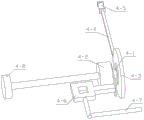
FIG. 6 is a first schematic structural diagram of a mobile device;
FIG. 7 is a second schematic structural diagram of a mobile device;
FIG. 8 is a schematic structural view of the position limiting device;
FIG. 9 is a schematic structural view of the clamping turntable;
FIG. 10 is a schematic structural view of the pressing device;
fig. 11 is a schematic structural view of the locking device.
In the figure: a carrier device 1; a carrier 1-1; 1-2 parts of a pore plate; 1-3 cutter grooves; 1-4 of U-shaped blocks; 1-5 of T-shaped vertical columns; a vertical plate 1-6; 1-7 of a rectangular chute; 1-8 of a slide rail; 1-9 parts of vertical sliding chute; a cutting device 2; 2-1 of upper frame; 2-2 of lower frame; an upper motor 2-3; a lower motor 2-4; 2-5 parts of a cutter; 2-6 parts of a double-shaft motor I; 2-7 parts of a screw rod; a runner 3; 3-1 of a vertical rod; 3-2 of limiting pieces; 3-3 of a slide block; 3-4 of a sliding groove block; 3-5 of a vertical chute; a mobile device 4; 4-1 of a hollow rotating block; a double-shaft motor II 4-2; 4-3 of a turntable; 4-4 parts of a cross bar; 4-5 of a sliding column; 4-6 of hollow slabs; pulling the handle 4-7; 4-8 of rollers; a limiting device 5; 5-1 of a U-shaped seat; 5-2 parts of a double-shaft motor III; 5-3 of a screw mandrel II; layering I5-4; a workpiece 6; a clamping turntable 7; a double-layer plate 7-1; 7-2 of a hollow seat; 7-3 of a rotating wheel handle; 7-4 of an electric push rod; 7-5 of vertical holes; hinge seats 7-6; 7-7 of a pressure plate; a pressing device 8; a U-shaped sliding plate 8-1; 8-2 of a push column; 8-3 of a slide bar; 8-4 parts of an L-shaped plate; 8-5 of a bevel block; a locking device 9; layering II 9-1; an inclined plane column 9-2; and a fixing plate 9-3.
Detailed Description
In the description of the present invention, it is to be understood that the terms "center", "longitudinal", "lateral", "upper", "lower", "front", "rear", "left", "right", "vertical", "horizontal", "top", "bottom", "inner", "outer", etc., indicate orientations or positional relationships based on those shown in the drawings, and are used only for convenience in describing and simplifying the description, but do not indicate or imply that the devices or elements referred to must have a particular orientation, be constructed and operated in a particular orientation, and therefore are not to be construed as limiting the invention, and further, the terms "first", "second", etc., are used only for descriptive purposes and are not intended to indicate or imply relative importance or to implicitly indicate the number of technical features indicated, whereby the features defined as "first", "second", etc., may explicitly or implicitly include one or more of such features, in the description of the present invention, "a plurality" means two or more unless otherwise specified.
The first embodiment is as follows:
the following describes the present embodiment with reference to fig. 1 to 11, and the present invention relates to the technical field of cutting machines, and more specifically to an angle-adjustable cutting machine, which includes a carrying device 1, a cutting device 2, a sliding device 3, a moving device 4, a limiting device 5, a workpiece 6, a clamping turntable 7, a pressing device 8, and a locking device 9.
The bearing device 1 is connected with a sliding device 3 in a sliding way, the sliding device 3 is provided with a cutting device 2, the cutting device 2 is connected with the bearing device 1 in a sliding way, a moving device 4 is connected with the bearing device 1 in a sliding way, the moving device 4 is connected with the sliding device 3 in a sliding way, a limiting device 5 is fixedly connected at the lower end of the bearing device 1, the workpiece 6 can be clamped through the limiting device 5, the upper part of the workpiece 6 is attached to the moving device 4, the clamping rotary table 7 is rotatably connected to the bearing device 1, the clamping rotary table 7 can clamp the workpiece 6, the pressing device 8 is in sliding connection with the bearing device 1, the pressing device 8 is in sliding connection with the clamping rotary table 7, two locking devices 9 are arranged, the two locking devices 9 are symmetrically installed, the two locking devices 9 are respectively and symmetrically and fixedly connected to the left end and the right end of the bearing device 1, and the two locking devices 9 are respectively attached to the left end and the right end of the pressing device 8; work piece 6 can be placed on bearing device 1, cutting device 2 plays the function of cutting the upper and lower both ends of work piece 6 simultaneously, slide device 3 plays and carries out spacing effect to cutting device 2, mobile device 4 can make slide device 3 slide around on bearing device 1, mobile device 4 can make work piece 6 carry forward, stop device 5 can make work piece 6 can not take place the mistake and rotate, press from both sides tight carousel 7 and play the function of being convenient for adjust the cutting angle of work piece 6, can make through pressing device 8 press from both sides tight carousel 7 and locking device 9 and carry out the function that presss from both sides tightly in turn to work piece 6, then be convenient for adjust the cutting angle of work piece 6.
The second embodiment is as follows:
the embodiment is described below with reference to fig. 1 to 11, and the embodiment will be further described, wherein the carrying device 1 includes a carrying frame 1-1, a hole plate 1-2, a slot 1-3, a U-shaped block 1-4, a T-shaped upright 1-5, a vertical plate 1-6, a rectangular sliding groove 1-7, a sliding rail 1-8 and a vertical sliding groove i 1-9, the rear portion of the carrying frame 1-1 is fixedly connected with the hole plate 1-2, the middle portion of the carrying frame 1-1 is provided with the slot 1-3, the lower portion of the rear end of the carrying frame 1-1 is fixedly connected with the U-shaped block 1-4, the carrying frame 1-1 is fixedly connected with the T-shaped upright 1-5, the right portion of the carrying frame 1-1 is fixedly connected with the vertical plate 1-6, the upper and lower ends of the vertical plate 1-6 are provided, the upper end and the lower end of each vertical plate 1-6 are respectively provided with a sliding rail 1-8, and the rear part of each vertical plate 1-6 is provided with a vertical sliding groove I1-9; the workpiece 6 can be placed on the carriage 1-1, thereby facilitating simultaneous cutting of both sides of the workpiece 6; the U-shaped blocks 1-4 play a limiting role.
The third concrete implementation mode:
the second embodiment is further described with reference to fig. 1-11, wherein the cutting device 2 includes an upper frame 2-1, a lower frame 2-2, an upper motor 2-3, a lower motor 2-4, a cutter 2-5, a dual-shaft motor i 2-6 and a screw rod i 2-7, the upper frame 2-1 is fixedly connected with the upper motor 2-3, the front and rear ends of the lower frame 2-2 are fixedly connected with the lower motor 2-4 through a long rod, the output shafts of the upper motor 2-3 and the two lower motors 2-4 are fixedly connected with the cutter 2-5, the two cutters 2-5 at the lower end slide in the cutter grooves 1-3, the output shafts at the upper and lower ends of the dual-shaft motor i 2-6 are respectively and symmetrically and fixedly connected with the two screw rods i 2-7, the upper frame 2-1 and the lower frame 2-2 are in threaded transmission connection with two screw rods I2-7 respectively; the upper motor 2-3 and the two lower motors 2-4 can be started to rotate, so that the plurality of cutters 2-5 respectively rotate by taking the axes of the cutters as shafts, and then both sides of the workpiece 6 are cut simultaneously, the upper frame 2-1 and the lower frame 2-2 can be moved in the directions away from or close to each other by starting the double-shaft motor I2-6 to rotate, and then the plurality of cutters 2-5 can be used for cutting both sides of the workpiece 6 simultaneously; the rotating directions of the cutters 2-5 are the same, so that the upper end and the lower end of the workpiece 6 bear the forces from the cutters 2-5 in opposite directions respectively, and the stable effect of the workpiece 6 in the cutting process is improved finally.
The fourth concrete implementation mode:
the third embodiment is further described with reference to fig. 1-11, wherein the sliding device 3 includes a vertical rod 3-1, a limiting piece 3-2, a sliding block 3-3, a sliding groove block 3-4 and a vertical sliding groove ii 3-5, the vertical rod 3-1 is provided with a plurality of limiting pieces 3-2, the upper and lower ends of the vertical rod 3-1 are fixedly connected with the sliding blocks 3-3, the two sliding blocks 3-3 are respectively slidably connected in the two sliding rails 1-8, the sliding groove block 3-4 is fixedly connected with the vertical rod 3-1, the sliding groove block 3-4 is provided with the vertical sliding groove ii 3-5, and the upper frame 2-1 and the lower frame 2-2 are respectively slidably connected at the upper and lower ends of the vertical rod 3-1; when the double-shaft motor I2-6 is started to rotate, the upper frame 2-1 and the lower frame 2-2 slide on the vertical rod 3-1; the vertical rod 3-1 and the limiting sheet 3-2 play a limiting role.
The fifth concrete implementation mode:
the fourth embodiment is further described with reference to fig. 1-11, wherein the moving device 4 includes a hollow rotating block 4-1, a dual-shaft motor ii 4-2, a rotating disc 4-3, a cross bar 4-4, a sliding column 4-5, a hollow plate 4-6, a pulling handle 4-7 and a roller 4-8, the left end of the hollow rotating block 4-1 is fixedly connected with the dual-shaft motor ii 4-2, an output shaft at the right end of the dual-shaft motor ii 4-2 penetrates through the hollow rotating block 4-1, the rotating disc 4-3 is fixedly connected to the output shaft at the right end of the dual-shaft motor ii 4-2, the cross bar 4-4 is hinged to the eccentric position of the rotating disc 4-3, the sliding column 4-5 is fixedly connected to the cross bar 4-4, the sliding column 4-5 is slidably connected to the vertical sliding groove ii 3-5, the left end of the hollow rotating block 4-1 is fixedly connected with a hollow plate 4-6, the hollow plate 4-6 is connected to a T-shaped vertical column 1-5 in a sliding mode, a tension spring is sleeved between the hollow plate 4-6 and the bearing frame 1-1, the rear portion of the hollow plate 4-6 is fixedly connected with a pulling handle 4-7, an output shaft at the right end of the double-shaft motor II 4-2 is fixedly connected with a roller 4-8, and the hollow rotating block 4-1 is connected into a vertical sliding groove I1-9 in a sliding mode; under the action of the tension spring, the hollow plate 4-6 drives the double-shaft motor II 4-2 to move downwards, the roller 4-8 is attached to the upper part of the workpiece 6 at the moment, and the hollow rotating block 4-1 slides in the vertical sliding groove I1-9 at the moment; by starting the double-shaft motor II 4-2 to rotate, the roller 4-8 can rotate by taking the axis of the roller as a shaft, so that the workpiece 6 is conveyed forwards; the transverse rod 4-4 can rotate by starting the double-shaft motor II 4-2 to rotate by taking the axis of the rotary table 4-3 as a shaft, so that the sliding chute blocks 3-4 are driven by the sliding columns 4-5 to slide back and forth in the rectangular sliding chutes 1-7, the sliding columns 4-5 slide up and down in the vertical sliding chutes II 3-5, the two sliding blocks 3-3 respectively slide back and forth in the two sliding rails 1-8, and then the plurality of cutters 2-5 move while cutting the two ends of the workpiece 6, and finally the cutting effect on the workpiece 6 is improved.
The sixth specific implementation mode:
this embodiment will be described with reference to fig. 1 to 11, and a fifth embodiment will be further described, the limiting device 5 comprises a U-shaped seat 5-1, a double-shaft motor III 5-2, a screw rod II 5-3 and press strips I5-4, the U-shaped seat 5-1 is fixedly connected to the lower portion of the front end of the bearing frame 1-1, the double-shaft motor III 5-2 is fixedly connected to the U-shaped seat 5-1, two screw rods II 5-3 are symmetrically and fixedly connected to output shafts of the left end and the right end of the double-shaft motor III 5-2 respectively, the press strips I5-4 are provided with two, the two press strips I5-4 are symmetrically installed, the two press strips I5-4 are in threaded transmission connection with the two screw rods II 5-3 respectively, an arc-shaped plate I is fixedly connected to each of the two press strips I5-4, and each of the two press strips I5-4; the double-shaft motor III 5-2 is started to rotate, so that the two screw rods II 5-3 rotate by taking the axes of the screw rods II 5-3 as shafts respectively, then the two pressing strips I5-4 are driven to move towards the directions close to or away from each other, the workpiece 6 can be clamped through the two arc-shaped plates I, and the effect of preventing the workpiece 6 from rotating by mistake is achieved.
The seventh embodiment:
the sixth embodiment is further described with reference to fig. 1 to 11, wherein the workpiece 6 is placed on the bearing frame 1-1, the workpiece 6 can be clamped through the two arc-shaped plates i, and the rollers 4 to 8 are attached to the upper part of the workpiece 6; the upper side and the lower side of the workpiece 6 can be cut by the plurality of cutters 2-5, and the placing angle of the workpiece 6 can be adjusted during cutting, so that the function of adjusting the angle of the device is realized.
The specific implementation mode is eight:
the embodiment is described below with reference to fig. 1 to 11, and the seventh embodiment is further described, in which the clamping rotary table 7 includes a double-layer plate 7-1, a hollow seat 7-2, a rotating wheel handle 7-3, an electric push rod 7-4, a vertical hole 7-5, a hinge seat 7-6 and a press plate 7-7, the hollow seat 7-2 is installed at the rear part of the double-layer plate 7-1, the hollow seat 7-2 is rotatably connected in the hole plate 1-2, the rotating wheel handle 7-3 is fixedly connected to the hollow seat 7-2, the electric push rod 7-4 is fixedly connected to the front end of the double-layer plate 7-1, the vertical hole 7-5 is respectively arranged at the left end and the right end of the front part of the double-layer plate 7-1, the hinge seat 7-6 is respectively fixedly connected to the left end and the right end of, the two hinged seats 7-6 are hinged with pressure plates 7-7, and the workpiece 6 can be clamped through the two pressure plates 7-7; the hollow seat 7-2 can rotate by taking the axis of the hollow seat as a shaft by adjusting the rotating wheel handle 7-3, so that the placing angle of the workpiece 6 can be conveniently adjusted; the workpiece 6 can be clamped through the two pressing plates 7-7, so that the convenience in adjusting the placing angle of the adjusted workpiece 6 is improved.
The specific implementation method nine:
the embodiment is described below with reference to fig. 1-11, and the eighth embodiment is further described, wherein the pressing device 8 includes a U-shaped sliding plate 8-1, push posts 8-2, a sliding rod 8-3, an L-shaped plate 8-4, and an inclined plane block 8-5, the left and right ends of the U-shaped sliding plate 8-1 are fixedly connected with the push posts 8-2, the two push posts 8-2 are respectively connected with two pressing plates 7-7 in a sliding manner, the rear portion of the U-shaped sliding plate 8-1 is fixedly connected with the sliding rod 8-3, the sliding rod 8-3 is connected with the L-shaped plate 8-4 in a hinged manner, the L-shaped plate 8-4 is fixedly connected with the inclined plane block 8-5, the L-shaped plate 8-4 is connected with the U-shaped block 1-4 in a sliding manner, the U-shaped sliding plate 8-1 is fixedly connected with the, the left end and the right end of the U-shaped sliding plate 8-1 are respectively connected in the two vertical holes 7-5 in a sliding manner, and the sliding rod 8-3 is connected in the hollow seat 7-2 in a sliding manner; the U-shaped sliding plate 8-1 can move back and forth by starting the electric push rod 7-4 to stretch, and at the moment, the sliding rod 8-3 slides in the hollow seat 7-2, so that the L-shaped plate 8-4 drives the bevel block 8-5 to move back and forth.
The detailed implementation mode is ten:
this embodiment will be described with reference to fig. 1 to 11, and this embodiment will further describe embodiment nine, the locking device 9 comprises a pressing strip II 9-1, an inclined plane column 9-2 and a fixing plate 9-3, the lower end of the pressing strip II 9-1 is fixedly connected with the inclined plane column 9-2, a spring is sleeved between the pressing strip II 9-1 and the fixing plate 9-3, the fixing plate 9-3 is fixedly connected on the bearing frame 1-1, two locking devices 9 are arranged, the two locking devices 9 are symmetrically installed, the two pressing strips II 9-1 are both in sliding connection with the pressing strip II 9-1, the two pressing strips II 9-1 are both fixedly connected with an arc-shaped plate II, the workpiece 6 can be clamped through the two arc-shaped plates II, and the two inclined plane columns 9-2 are respectively attached to the left end and the right end of the inclined plane block 8-5; when the L-shaped plate 8-4 drives the inclined plane block 8-5 to move back and forth, the two inclined plane columns 9-2 are respectively attached to the left side and the right side of the inclined plane block 8-5, so that the two pressing strips II 9-1 are driven to move towards or away from each other; due to the design of the springs, the two arc-shaped plates II always have the tendency of clamping the workpiece 6; when the electric push rod 7-4 extends out, the U-shaped sliding plate 8-1 drives the two push posts 8-2 to enable the two press plates 7-7 to respectively press the left end and the right end of the workpiece 6, and at the moment, the L-shaped plate 8-4 moves backwards under the driving of the U-shaped sliding plate 8-1, so that the inclined surfaces on the two sides of the inclined surface block 8-5 respectively push the two inclined surface blocks 8-5 to move in the directions away from each other; when the electric push rod 7-4 contracts, the U-shaped sliding plate 8-1 drives the two push posts 8-2 to enable the two pressing plates 7-7 to respectively loosen the left end and the right end of the workpiece 6, the L-shaped plate 8-4 moves forwards under the driving of the U-shaped sliding plate 8-1, the two inclined plane posts 9-2 are respectively attached to the left side and the right side of the inclined plane block 8-5 under the action of the spring, and the workpiece 6 can be clamped by the two arc-shaped plates II; the two pressing plates 7-7 and the two arc-shaped plates II are alternately tightened, so that the cutting angle of the workpiece 6 can be conveniently adjusted.
The working principle of the angle-adjustable cutting machine is as follows:
the workpiece 6 can be placed on the carriage 1-1, thereby facilitating simultaneous cutting of both sides of the workpiece 6; the U-shaped blocks 1-4 play a limiting role; the upper motor 2-3 and the two lower motors 2-4 can be started to rotate, so that the plurality of cutters 2-5 respectively rotate by taking the axes of the cutters as shafts, and then both sides of the workpiece 6 are cut simultaneously, the upper frame 2-1 and the lower frame 2-2 can be moved in the directions away from or close to each other by starting the double-shaft motor I2-6 to rotate, and then the plurality of cutters 2-5 can be used for cutting both sides of the workpiece 6 simultaneously; the rotating directions of the cutters 2-5 are the same, so that the upper end and the lower end of the workpiece 6 bear the forces from the cutters 2-5 in opposite directions respectively, and the stable effect of the workpiece 6 in the cutting process is improved finally; when the double-shaft motor I2-6 is started to rotate, the upper frame 2-1 and the lower frame 2-2 slide on the vertical rod 3-1; the vertical rod 3-1 and the limiting piece 3-2 play a limiting role; under the action of the tension spring, the hollow plate 4-6 drives the double-shaft motor II 4-2 to move downwards, the roller 4-8 is attached to the upper part of the workpiece 6 at the moment, and the hollow rotating block 4-1 slides in the vertical sliding groove I1-9 at the moment; by starting the double-shaft motor II 4-2 to rotate, the roller 4-8 can rotate by taking the axis of the roller as a shaft, so that the workpiece 6 is conveyed forwards; the transverse rod 4-4 can rotate by starting the double-shaft motor II 4-2 to rotate by taking the axis of the rotary table 4-3 as a shaft, so that the sliding chute blocks 3-4 are driven by the sliding columns 4-5 to slide back and forth in the rectangular sliding chutes 1-7, the sliding columns 4-5 slide up and down in the vertical sliding chutes II 3-5, the two sliding blocks 3-3 respectively slide back and forth in the two sliding rails 1-8, and then the plurality of cutters 2-5 move while cutting the two ends of the workpiece 6, and finally the cutting effect on the workpiece 6 is improved; the double-shaft motor III 5-2 is started to rotate, so that the two screw rods II 5-3 rotate by taking the axes of the screw rods II 5-3 as shafts respectively, the two pressing strips I5-4 are driven to move towards the directions close to or away from each other, the workpiece 6 can be clamped through the two arc-shaped plates I, and the effect of preventing the workpiece 6 from rotating by mistake is achieved; the upper side and the lower side of the workpiece 6 can be cut by the plurality of cutters 2-5, and the placing angle of the workpiece 6 can be adjusted during cutting, so that the function of adjusting the angle of the device is realized; the hollow seat 7-2 can rotate by taking the axis of the hollow seat as a shaft by adjusting the rotating wheel handle 7-3, so that the placing angle of the workpiece 6 can be conveniently adjusted; the workpiece 6 can be clamped through the two pressing plates 7-7, so that the convenience in adjusting the placing angle of the workpiece 6 is improved; the U-shaped sliding plate 8-1 can move back and forth by starting the electric push rod 7-4 to stretch, and at the moment, the sliding rod 8-3 slides in the hollow seat 7-2, so that the L-shaped plate 8-4 drives the bevel block 8-5 to move back and forth; when the L-shaped plate 8-4 drives the inclined plane block 8-5 to move back and forth, the two inclined plane columns 9-2 are respectively attached to the left side and the right side of the inclined plane block 8-5, so that the two pressing strips II 9-1 are driven to move towards or away from each other; due to the design of the springs, the two arc-shaped plates II always have the tendency of clamping the workpiece 6; when the electric push rod 7-4 extends out, the U-shaped sliding plate 8-1 drives the two push posts 8-2 to enable the two press plates 7-7 to respectively press the left end and the right end of the workpiece 6, and at the moment, the L-shaped plate 8-4 moves backwards under the driving of the U-shaped sliding plate 8-1, so that the inclined surfaces on the two sides of the inclined surface block 8-5 respectively push the two inclined surface blocks 8-5 to move in the directions away from each other; when the electric push rod 7-4 contracts, the U-shaped sliding plate 8-1 drives the two push posts 8-2 to enable the two pressing plates 7-7 to respectively loosen the left end and the right end of the workpiece 6, the L-shaped plate 8-4 moves forwards under the driving of the U-shaped sliding plate 8-1, the two inclined plane posts 9-2 are respectively attached to the left side and the right side of the inclined plane block 8-5 under the action of the spring, and the workpiece 6 can be clamped by the two arc-shaped plates II; the two pressing plates 7-7 and the two arc-shaped plates II are alternately tightened, so that the cutting angle of the workpiece 6 can be conveniently adjusted.
It is to be understood that the above description is not intended to limit the present invention, and the present invention is not limited to the above examples, and that various changes, modifications, additions and substitutions which are within the spirit and scope of the present invention and which may be made by those skilled in the art are also within the scope of the present invention.
Claims (10)
1. Angle-adjustable cutting machine, including bearing device (1), cutting device (2), slider (3), mobile device (4), stop device (5), work piece (6), clamping turntable (7), pressure move device (8) and locking device (9), its characterized in that: the device is characterized in that a sliding device (3) is connected onto the bearing device (1) in a sliding manner, a cutting device (2) is installed on the sliding device (3), the cutting device (2) is connected with the bearing device (1) in a sliding manner, a moving device (4) is connected with the bearing device (1) in a sliding manner, a limiting device (5) is fixedly connected to the lower end of the bearing device (1), a workpiece (6) can be clamped through the limiting device (5), the upper part of the workpiece (6) is attached to the moving device (4), a clamping turntable (7) is rotatably connected onto the bearing device (1), the clamping turntable (7) can clamp the workpiece (6), a pressing device (8) is connected with the bearing device (1) in a sliding manner, the pressing device (8) is connected with the clamping turntable (7) in a sliding manner, and two locking devices (9) are arranged, the two locking devices (9) are symmetrically installed, the two locking devices (9) are respectively and symmetrically and fixedly connected to the left end and the right end of the bearing device (1), and the two locking devices (9) are respectively attached to the left end and the right end of the pressing device (8).
2. The adjustable angle cutting machine according to claim 1, wherein: the bearing device (1) comprises a bearing frame (1-1), a hole plate (1-2), a cutter groove (1-3), a U-shaped block (1-4), a T-shaped vertical column (1-5), a vertical plate (1-6), a rectangular sliding groove (1-7), a sliding rail (1-8) and a vertical sliding groove I (1-9), wherein the rear part of the bearing frame (1-1) is fixedly connected with the hole plate (1-2), the middle part of the bearing frame (1-1) is provided with the cutter groove (1-3), the lower part of the rear end of the bearing frame (1-1) is fixedly connected with the U-shaped block (1-4), the bearing frame (1-1) is fixedly connected with the T-shaped vertical column (1-5), the right part of the bearing frame (1-1) is fixedly connected with the vertical plate (1-6), the upper end and the lower end of the vertical plate (1, the upper end and the lower end of each vertical plate (1-6) are respectively provided with a sliding rail (1-8), and the rear part of each vertical plate (1-6) is provided with a vertical sliding groove I (1-9).
3. The adjustable angle cutting machine according to claim 2, wherein: the cutting device (2) comprises an upper frame (2-1), a lower frame (2-2), an upper motor (2-3), a lower motor (2-4), cutters (2-5), a double-shaft motor I (2-6) and screw rods I (2-7), wherein the upper motor (2-3) is fixedly connected to the upper frame (2-1), the lower motor (2-4) is fixedly connected to the front end and the rear end of the lower frame (2-2) through long rods, the cutters (2-5) are fixedly connected to output shafts of the upper motor (2-3) and the two lower motors (2-4), the two cutters (2-5) positioned at the lower end slide in the cutter grooves (1-3), and the two screw rods I (2-7) are symmetrically and fixedly connected to output shafts at the upper end and the lower end of the double-shaft motor I (2-6) respectively, the upper frame (2-1) and the lower frame (2-2) are in threaded transmission connection with the two screw rods I (2-7) respectively.
4. The adjustable angle cutting machine according to claim 3, wherein: the sliding device (3) comprises a vertical rod (3-1), limiting pieces (3-2), sliding blocks (3-3), sliding groove blocks (3-4) and vertical sliding grooves II (3-5), wherein the vertical rod (3-1) is provided with the limiting pieces (3-2), the upper end and the lower end of the vertical rod (3-1) are fixedly connected with the sliding blocks (3-3), the two sliding blocks (3-3) are respectively connected in the two sliding rails (1-8) in a sliding mode, the sliding groove blocks (3-4) are fixedly connected with the vertical rod (3-1), the sliding groove blocks (3-4) are provided with the vertical sliding grooves II (3-5), and the upper frame (2-1) and the lower frame (2-2) are respectively connected at the upper end and the lower end of the vertical rod (3-1) in a sliding mode.
5. The adjustable angle cutting machine according to claim 4, wherein: the moving device (4) comprises a hollow rotating block (4-1), a double-shaft motor II (4-2), a rotating disc (4-3), a cross rod (4-4), a sliding column (4-5), a hollow plate (4-6), a pulling handle (4-7) and a roller (4-8), the double-shaft motor II (4-2) is fixedly connected to the left end of the hollow rotating block (4-1), an output shaft at the right end of the double-shaft motor II (4-2) penetrates through the hollow rotating block (4-1), the rotating disc (4-3) is fixedly connected to an output shaft at the right end of the double-shaft motor II (4-2), the cross rod (4-4) is hinged to the eccentric position of the rotating disc (4-3), the sliding column (4-5) is fixedly connected to the cross rod (4-4), and the sliding column (4-5) is slidably connected to the vertical sliding groove II (3-5), the left end of the hollow rotating block (4-1) is fixedly connected with a hollow plate (4-6), the hollow plate (4-6) is connected to the T-shaped vertical column (1-5) in a sliding mode, a tension spring is sleeved between the hollow plate (4-6) and the bearing frame (1-1), the rear portion of the hollow plate (4-6) is fixedly connected with a pulling handle (4-7), an output shaft at the right end of the double-shaft motor II (4-2) is fixedly connected with a roller (4-8), and the hollow rotating block (4-1) is connected into the vertical sliding groove I (1-9) in a sliding mode.
6. The adjustable angle cutting machine according to claim 5, wherein: the limiting device (5) comprises a U-shaped seat (5-1) and a double-shaft motor III (5-2), the pressing device comprises a screw II (5-3) and pressing strips I (5-4), a U-shaped seat (5-1) is fixedly connected to the lower portion of the front end of a bearing frame (1-1), a double-shaft motor III (5-2) is fixedly connected to the U-shaped seat (5-1), two screw II (5-3) are symmetrically and fixedly connected to output shafts at the left end and the right end of the double-shaft motor III (5-2) respectively, the number of the pressing strips I (5-4) is two, the two pressing strips I (5-4) are symmetrically installed, the two pressing strips I (5-4) are in threaded transmission connection with the two screw II (5-3) respectively, an arc-shaped plate I is fixedly connected to the two pressing strips I (5-4), and the two pressing strips I (5-4) are in sliding connection with the bearing frame.
7. The adjustable angle cutting machine according to claim 6, wherein: the workpiece (6) is placed on the bearing frame (1-1), the workpiece (6) can be clamped through the two arc-shaped plates I, and the rollers (4-8) are attached to the upper portion of the workpiece (6).
8. The adjustable angle cutting machine according to claim 7, wherein: the clamping rotary table (7) comprises a double-layer plate (7-1), a hollow seat (7-2), a rotating wheel handle (7-3), an electric push rod (7-4), vertical holes (7-5), a hinged seat (7-6) and a pressing plate (7-7), the hollow seat (7-2) is installed at the rear part of the double-layer plate (7-1), the hollow seat (7-2) is rotatably connected in the hole plate (1-2), the rotating wheel handle (7-3) is fixedly connected on the hollow seat (7-2), the electric push rod (7-4) is fixedly connected on the front end of the double-layer plate (7-1), the vertical holes (7-5) are respectively arranged at the left end and the right end of the front part of the double-layer plate (7-1), the hinged seat (7-6) is fixedly connected at the left end and the right end of the front part of the double-, the two hinged seats (7-6) are hinged with pressure plates (7-7), and the workpiece (6) can be clamped through the two pressure plates (7-7).
9. The adjustable angle cutting machine according to claim 8, wherein: the pressing device (8) comprises a U-shaped sliding plate (8-1), push posts (8-2), a sliding rod (8-3), an L-shaped plate (8-4) and an inclined surface block (8-5), the left end and the right end of the U-shaped sliding plate (8-1) are fixedly connected with the push posts (8-2), the two push posts (8-2) are respectively connected with two pressing plates (7-7) in a sliding manner, the rear part of the U-shaped sliding plate (8-1) is fixedly connected with the sliding rod (8-3), the sliding rod (8-3) is hinged with the L-shaped plate (8-4), the inclined surface block (8-5) is fixedly connected on the L-shaped plate (8-4), the L-shaped plate (8-4) is connected on the U-shaped block (1-4) in a sliding manner, the U-shaped sliding plate (8-1) is fixedly connected with the movable end of an electric push rod (, the left end and the right end of the U-shaped sliding plate (8-1) are respectively connected in the two vertical holes (7-5) in a sliding manner, and the sliding rod (8-3) is connected in the hollow seat (7-2) in a sliding manner.
10. The adjustable angle cutting machine according to claim 9, wherein: the locking device (9) comprises a pressing strip II (9-1), inclined plane columns (9-2) and a fixing plate (9-3), the lower end of the pressing strip II (9-1) is fixedly connected with the inclined plane columns (9-2), a spring is sleeved between the pressing strip II (9-1) and the fixing plate (9-3), the fixing plate (9-3) is fixedly connected to the bearing frame (1-1), the two locking devices (9) are symmetrically arranged, the two pressing strips II (9-1) are both in sliding connection with the pressing strip II (9-1), the two pressing strips II (9-1) are both fixedly connected with an arc-shaped plate II, the workpiece (6) can be clamped through the two arc-shaped plates II, and the two inclined plane columns (9-2) are respectively attached to the left end and the right end of the inclined plane block (8-5).
Priority Applications (1)
| Application Number | Priority Date | Filing Date | Title |
|---|---|---|---|
| CN202011269395.7A CN112405041B (en) | 2020-11-13 | 2020-11-13 | Angle-adjustable cutting machine |
Applications Claiming Priority (1)
| Application Number | Priority Date | Filing Date | Title |
|---|---|---|---|
| CN202011269395.7A CN112405041B (en) | 2020-11-13 | 2020-11-13 | Angle-adjustable cutting machine |
Publications (2)
| Publication Number | Publication Date |
|---|---|
| CN112405041A true CN112405041A (en) | 2021-02-26 |
| CN112405041B CN112405041B (en) | 2022-01-14 |
Family
ID=74832586
Family Applications (1)
| Application Number | Title | Priority Date | Filing Date |
|---|---|---|---|
| CN202011269395.7A Active CN112405041B (en) | 2020-11-13 | 2020-11-13 | Angle-adjustable cutting machine |
Country Status (1)
| Country | Link |
|---|---|
| CN (1) | CN112405041B (en) |
Cited By (1)
| Publication number | Priority date | Publication date | Assignee | Title |
|---|---|---|---|---|
| CN116765517A (en) * | 2023-08-17 | 2023-09-19 | 靖江市国润警用器材制造有限公司 | Tear baton rigid rod cutting equipment |
Citations (5)
| Publication number | Priority date | Publication date | Assignee | Title |
|---|---|---|---|---|
| US20020148333A1 (en) * | 2001-04-16 | 2002-10-17 | Myers Kent J. | Automated pipe cutter tool box |
| CN106903470A (en) * | 2017-04-26 | 2017-06-30 | 北京林克曼数控技术股份有限公司 | The device and method of the axle double card disk built-up sectional material intersection of numerical control eight cutting |
| CN107838685A (en) * | 2017-12-14 | 2018-03-27 | 吴秋敏 | A kind of building structure rack splicing mild steel steel pipe automation cutting grinding apparatus |
| CN108994285A (en) * | 2018-07-28 | 2018-12-14 | 庄立 | A kind of municipal drainage tee tube casting matrix cutting equipment |
| KR102066574B1 (en) * | 2019-06-13 | 2020-01-15 | 박세준 | Copper tube cutting machine |
-
2020
- 2020-11-13 CN CN202011269395.7A patent/CN112405041B/en active Active
Patent Citations (5)
| Publication number | Priority date | Publication date | Assignee | Title |
|---|---|---|---|---|
| US20020148333A1 (en) * | 2001-04-16 | 2002-10-17 | Myers Kent J. | Automated pipe cutter tool box |
| CN106903470A (en) * | 2017-04-26 | 2017-06-30 | 北京林克曼数控技术股份有限公司 | The device and method of the axle double card disk built-up sectional material intersection of numerical control eight cutting |
| CN107838685A (en) * | 2017-12-14 | 2018-03-27 | 吴秋敏 | A kind of building structure rack splicing mild steel steel pipe automation cutting grinding apparatus |
| CN108994285A (en) * | 2018-07-28 | 2018-12-14 | 庄立 | A kind of municipal drainage tee tube casting matrix cutting equipment |
| KR102066574B1 (en) * | 2019-06-13 | 2020-01-15 | 박세준 | Copper tube cutting machine |
Cited By (2)
| Publication number | Priority date | Publication date | Assignee | Title |
|---|---|---|---|---|
| CN116765517A (en) * | 2023-08-17 | 2023-09-19 | 靖江市国润警用器材制造有限公司 | Tear baton rigid rod cutting equipment |
| CN116765517B (en) * | 2023-08-17 | 2023-11-10 | 靖江市国润警用器材制造有限公司 | Tear baton rigid rod cutting equipment |
Also Published As
| Publication number | Publication date |
|---|---|
| CN112405041B (en) | 2022-01-14 |
Similar Documents
| Publication | Publication Date | Title |
|---|---|---|
| CN107775222B (en) | Automatic spiral welding machine and welding method thereof | |
| CN106736596B (en) | A kind of Numerical control cutting building-block machine | |
| CN215241265U (en) | Automatic plate shifting cutting machine | |
| CN111438788A (en) | Furniture wooden door processing system and processing method | |
| CN211661229U (en) | Sawing machine equipment | |
| CN112405041B (en) | Angle-adjustable cutting machine | |
| CN109226879A (en) | A kind of high-velocity wire intelligence pipe cutting machine tool | |
| CN219465100U (en) | Processing cutting equipment for hollow plastic plate | |
| CN218983373U (en) | Aluminum plate shearing and conveying device | |
| CN216502545U (en) | Double-station double-side milling machine | |
| CN208743819U (en) | Automatic grinding saw type cutting machine | |
| CN107856195A (en) | A kind of graphite sawing machine with automatic feeding | |
| CN212793381U (en) | Steel plate edge cutting machine | |
| CN113369538A (en) | Vertical machining equipment and machining method | |
| CN210996830U (en) | Sawing material cutting device | |
| CN210172675U (en) | Automatic material loading position adjustable pipe cutting machine | |
| CN208245955U (en) | A kind of positioning device of band sawing machine | |
| CN206139907U (en) | No base sawing machine | |
| CN102554972A (en) | Full-automatic precision final trimming saw | |
| CN218984432U (en) | Double-station double-cutter-head cutting device | |
| CN220028807U (en) | Multi-station steel pipe cutting equipment | |
| CN218874436U (en) | Section bar cutting equipment convenient to location | |
| CN217799334U (en) | High-efficient cutting device of steel ingot blank | |
| CN212945785U (en) | Novel square steel cutting machine | |
| CN212419925U (en) | Efficient building board cutting device |
Legal Events
| Date | Code | Title | Description |
|---|---|---|---|
| PB01 | Publication | ||
| PB01 | Publication | ||
| SE01 | Entry into force of request for substantive examination | ||
| SE01 | Entry into force of request for substantive examination | ||
| TA01 | Transfer of patent application right |
Effective date of registration: 20211230 Address after: 225002 Dongxi Avenue, Gaoyou high tech Industrial Development Zone, Yangzhou City, Jiangsu Province Applicant after: Yangzhou Feng Feng hi tech Industry Investment Development Group Co.,Ltd. Address before: 150036 gate 1, 5th floor, unit 3, 71-1 Diantan Road, Xiangfang District, Harbin City, Heilongjiang Province Applicant before: Zhang Minghui |
|
| TA01 | Transfer of patent application right | ||
| GR01 | Patent grant | ||
| GR01 | Patent grant |