CN112382471A - Transformer accessory oil maintenance device and use method thereof - Google Patents
Transformer accessory oil maintenance device and use method thereof Download PDFInfo
- Publication number
- CN112382471A CN112382471A CN202011177500.4A CN202011177500A CN112382471A CN 112382471 A CN112382471 A CN 112382471A CN 202011177500 A CN202011177500 A CN 202011177500A CN 112382471 A CN112382471 A CN 112382471A
- Authority
- CN
- China
- Prior art keywords
- oil
- electric valve
- valve
- accessory
- vacuum
- Prior art date
- Legal status (The legal status is an assumption and is not a legal conclusion. Google has not performed a legal analysis and makes no representation as to the accuracy of the status listed.)
- Withdrawn
Links
Images


Classifications
-
- H—ELECTRICITY
- H01—ELECTRIC ELEMENTS
- H01F—MAGNETS; INDUCTANCES; TRANSFORMERS; SELECTION OF MATERIALS FOR THEIR MAGNETIC PROPERTIES
- H01F27/00—Details of transformers or inductances, in general
- H01F27/08—Cooling; Ventilating
- H01F27/10—Liquid cooling
- H01F27/12—Oil cooling
- H01F27/14—Expansion chambers; Oil conservators; Gas cushions; Arrangements for purifying, drying, or filling
-
- H—ELECTRICITY
- H01—ELECTRIC ELEMENTS
- H01F—MAGNETS; INDUCTANCES; TRANSFORMERS; SELECTION OF MATERIALS FOR THEIR MAGNETIC PROPERTIES
- H01F41/00—Apparatus or processes specially adapted for manufacturing or assembling magnets, inductances or transformers; Apparatus or processes specially adapted for manufacturing materials characterised by their magnetic properties
-
- H—ELECTRICITY
- H02—GENERATION; CONVERSION OR DISTRIBUTION OF ELECTRIC POWER
- H02B—BOARDS, SUBSTATIONS OR SWITCHING ARRANGEMENTS FOR THE SUPPLY OR DISTRIBUTION OF ELECTRIC POWER
- H02B3/00—Apparatus specially adapted for the manufacture, assembly, or maintenance of boards or switchgear
Landscapes
- Engineering & Computer Science (AREA)
- Power Engineering (AREA)
- Manufacturing & Machinery (AREA)
- Transformer Cooling (AREA)
Abstract
The invention relates to the field of electrical equipment maintenance, in particular to a transformer accessory oil service maintenance device and a using method thereof, wherein the transformer accessory oil service maintenance device comprises a box body, an equipment pipeline part and a control part; the equipment pipeline part and the control part are arranged in or on the box body. The invention can realize the functions of cleaning the inside of the transformer accessory, vacuumizing, vacuum oil injection, internal oil circulation, external oil circulation and oil pressure leakage test, adjusting and controlling the vacuum degree and the oil injection speed and the like, has the characteristics of multifunction and the like, and is convenient for workers to adopt different maintenance processes to operate different accessories. The invention can adjust the vacuum degree and the flow rate, and is convenient and practical in actual work. The invention has obvious use effect and solves the problem that the existing transformer accessories have no maintenance equipment for replacement. The invention can be automatically controlled in a single function, can also be controlled in a multifunctional integrated full-automatic way, and is convenient to operate. The control interface is simple and clear, the use is convenient, the operation is easy to operate, and the working efficiency can be improved.
Description
Technical Field
The invention relates to the field of electrical equipment maintenance, in particular to a transformer accessory oil service maintenance device and a using method thereof.
Background
In oil-immersed power transformers, a variety of oil-filled accessories are used, such as oil paper capacitive bushings, on-load tap changers, oil conservators, coolers, etc. For the maintenance of different accessories, different technological requirements such as internal cleaning, oil pressure leakage testing, circulating filtration, vacuum oil injection and the like exist, at present, a maintenance device developed for the maintenance of the transformer accessories is lacked in the whole industry, and due to the fact that the maintenance device of the transformer accessories is not equipped, the maintenance is replaced under many conditions, the maintenance cost is increased, a large amount of resources are wasted, the maintenance skill of maintenance personnel is declined due to the replacement maintenance for a long time, and equipment replacement of manufacturers is excessively depended.
Disclosure of Invention
In order to solve the problem that no technical equipment is used for overhauling the transformer accessories, the invention provides a transformer accessory oil service overhauling device and a using method thereof. The specific technical scheme is as follows:
a transformer accessory oil maintenance device comprises a box body, an equipment pipeline part and a control part; the equipment pipeline part and the control part are arranged in or on the box body; the equipment pipeline part comprises a vacuum machine, a sensor seat, a vacuum condenser blow-down valve, a vacuumizing electric valve, an exhaust electric valve, an oil injection electric valve, a fine filter, a blow-down valve, an oil pump, a coarse filter, an oil inlet valve, an oil outlet valve, an oil discharge bypass electric valve, a backpressure valve, an accessory sampling valve, a circulation selection electric valve and an accessory oil discharge electric valve;
the control part comprises a power supply circuit breaker, a vacuum machine variable frequency controller, an oil pump variable frequency controller, a control screen, a vacuum degree sensor, a fine filter pressure sensor and a back pressure valve pressure sensor;
one end of the sensor seat is connected with the vacuum machine, and the other end of the sensor seat is connected with the vacuum condenser and is used for installing a vacuum degree sensor; the vacuum machine is used for vacuumizing the transformer accessory; the vacuum condenser is used for condensing moisture brought out by vacuumizing the transformer accessories and containing oil spilling generated during vacuum oil injection of the transformer accessories;
the vacuum condenser, the vacuumizing electric valve and the transformer accessory are sequentially connected through a pipeline, and a condenser blow-down valve is installed at the bottom of the vacuum condenser; the vacuumizing electric valve is used for controlling the opening and closing of the vacuumizing pipeline; the condenser blow-down valve is used for discharging condensed water and dirty oil of the vacuum condenser;
the exhaust electric valve is connected in parallel with a pipeline for connecting the vacuumizing electric valve with the transformer accessory and is used for exhausting and breaking vacuum of the vacuumizing pipeline;
the oil inlet valve is connected with the oil tank; the oil inlet valve, the coarse filter, the oil pump, the fine filter and the oil injection electric valve are sequentially connected; a drain valve is arranged at the bottom of the fine filter; the oil injection electric valve is connected in parallel with a pipeline for connecting the vacuumizing electric valve with the transformer accessory;
the oil inlet valve is used for controlling the opening and closing of an oil inlet pipeline; the coarse filter is used for filtering impurities in the oil in advance; the oil pump is used for providing power for oil flow; the fine filter is used for filtering impurities in the oil and absorbing water in the oil; the blowdown valve is used for discharging impurities and dirty oil in the fine filter; the oil injection electric valve is used for controlling the opening and closing of the oil injection pipeline;
the oil outlet valve is connected with the oil tank and is respectively connected with the oil discharge bypass electric valve and the back pressure valve; the oil discharge bypass electric valve and the backpressure valve are respectively connected with an accessory oil discharge electric valve; the accessory oil discharge electric valve, the accessory sampling valve and the transformer accessory are sequentially connected through a pipeline; the circulation selection electric valve is respectively connected with the vacuumizing electric valve, the exhaust electric valve, the oil injection electric valve, the transformer accessory, the oil discharge bypass electric valve, the back pressure valve and the accessory oil discharge electric valve; the oil outlet valve is used for controlling the opening and closing of the oil outlet pipeline; the oil discharge bypass electric valve is used for controlling a branch loop of an oil outlet pipeline; the back pressure valve controls the conduction of an oil outlet pipeline when the oil discharge bypass electric valve is closed and the oil pressure reaches a preset value; the accessory sampling valve is used for collecting oil samples; the circulation selection electric valve is used for controlling whether oil flow passes through the transformer accessory or not; the accessory oil discharge electric valve is used for controlling the opening or closing of an oil flow channel inside the transformer accessory;
the power circuit breaker is respectively connected with the vacuum machine variable frequency controller and the oil pump variable frequency controller; the vacuum machine variable frequency controller, the oil pump variable frequency controller, the vacuum degree sensor, the fine filter pressure sensor and the back pressure valve pressure sensor are respectively connected with the control screen;
the power supply circuit breaker is connected with an alternating current power supply and is used for providing power for the vacuum machine and the oil pump;
the vacuum machine variable frequency controller is provided with alternating current voltage by a power supply circuit breaker and controls output frequency by a control screen;
the oil pump variable frequency controller is provided with alternating current voltage by a power supply circuit breaker and controls output frequency by a control panel;
the control screen is embedded on the box body;
the vacuum degree sensor is used for collecting vacuum degree signals of the vacuum machine and transmitting the vacuum degree signals to the control screen;
the fine filter pressure sensor is used for collecting the pressure inside the fine filter, transmitting the pressure to the control screen, automatically judging the filter element blockage degree and warning the replacement of the filter element;
the back pressure valve pressure sensor is used for collecting a back pressure valve pressure value, transmitting the back pressure valve pressure value to the control screen, providing a pressure build-up value of static pressure oil circulation, and adjusting the pressure value of the back pressure valve according to the pressure build-up value;
and the control screen receives signals of the vacuum degree sensor, the fine filter pressure sensor and the backpressure valve pressure sensor, displays the signals on the screen, and controls the output frequencies of the vacuum machine variable frequency controller and the oil pump variable frequency controller.
Preferably, the box body comprises a box shell, a bottom plate, rollers and a trolley handle; the bottom plate is fixedly arranged at the bottom of the box shell; the roller is arranged at the bottom of the bottom plate; the cart handle is installed on the case shell.
Preferably, the housing is in the shape of a hollow cuboid; the back-off is arranged on the bottom plate, and the inside of the bottom plate is supported and fixed by a framework welded by square pipes.
Preferably, the bottom plate is a square plate, and a square tube is fixed at the lower part of the bottom plate and used as a reinforcing rib to increase the strength.
Preferably, the rollers are four in number, are respectively installed at four top corners of the bottom plate and are fixedly connected with the reinforcing ribs.
Preferably, the two rollers installed at the front end of the bottom plate are respectively universal wheels, and the two rollers installed at the rear end of the bottom plate are respectively fixed wheels.
A use method of a transformer accessory oil maintenance device specifically comprises the following steps:
s1: initial setting: when all valves are in a closed state, connecting the device with an oil filling port and an oil discharging port of a transformer accessory, connecting an oil inlet valve with an oil tank, connecting an oil outlet valve with the oil tank, and opening the oil inlet valve and the oil outlet valve;
s2: oil discharge of transformer accessories: opening the exhaust electric valve, the accessory oil discharge electric valve and the oil discharge bypass electric valve, naturally draining transformer oil in a sleeve of the transformer accessory, and closing the exhaust electric valve, the accessory oil discharge electric valve and the oil discharge bypass electric valve;
s3: cleaning the transformer accessories: opening the vacuumizing electric valve, starting the vacuum machine, stopping the vacuum machine to stop vacuumizing when the vacuum count value of the vacuum degree sensor reaches a set value, and closing the vacuumizing electric valve;
opening an oil injection electric valve, starting an oil pump to inject oil, stopping oil injection of the oil pump after transformer accessories are full of oil, closing the oil injection electric valve until the standing time is met, opening an accessory oil discharge electric valve and an oil discharge bypass electric valve, then opening an exhaust electric valve, naturally discharging oil, exhausting transformer oil in the transformer accessories, and closing the exhaust electric valve, the accessory oil discharge electric valve and the oil discharge bypass electric valve;
s4: vacuumizing the transformer accessory: opening the vacuumizing electric valve, starting the vacuum machine, starting a countdown until the vacuum count value of the vacuum degree sensor meets the requirement, stopping vacuumizing by the vacuum machine until the vacuumizing time is met, and closing the vacuumizing electric valve;
s5: vacuum oil injection of transformer accessories: the oil inlet pipe and the oil outlet pipe are both connected with an oil tank, a vacuumizing electric valve is opened, a vacuum machine is started, when the vacuum count value of the vacuum degree sensor meets the requirement, countdown is started until the evacuation time is met, the oil outlet valve, the oil discharge bypass electric valve and the accessory oil discharge electric valve are opened, after the transformer accessory is full of oil, the oil outlet valve, the oil discharge bypass electric valve and the accessory oil discharge electric valve are closed, oil injection is stopped, the vacuum machine stops vacuumizing, and the vacuumizing electric valve is closed;
s6: static pressure oil circulation of transformer accessories: the oil inlet pipe and the oil outlet pipe are connected with an oil tank, an oil injection electric valve is opened, a circulation selection electric valve is opened, the oil pump is started to continue injecting oil, a backpressure valve is opened, countdown is started until the circulation time is met, the oil pump is stopped, the oil injection electric valve is closed, and the circulation selection electric valve is closed;
s7: the transformer accessory conventional oil circulates, the oil inlet pipe and the oil discharge pipe are both connected with the oil tank, the oil injection electric valve is opened, the accessory oil discharge electric valve and the oil discharge bypass electric valve are opened, the oil pump is started to continue oil injection, the countdown is started until the circulation time is met, the oil pump is stopped, the oil injection electric valve is closed, and the accessory oil discharge electric valve and the oil discharge bypass electric valve are closed.
The invention has the beneficial effects that: the invention can realize the functions of cleaning the inside of the transformer accessory, vacuumizing, vacuum oil injection, internal oil circulation, external oil circulation and oil pressure leakage test, adjusting and controlling the vacuum degree and the oil injection speed and the like, has the characteristics of multifunction and the like, and is convenient for workers to adopt different maintenance processes to operate different accessories.
The invention can adjust the vacuum degree and the flow rate, and is convenient and practical in actual work. The invention has obvious use effect and solves the problem that the existing transformer accessories have no maintenance equipment for replacement. The invention can be automatically controlled in a single function, can also be controlled in a multifunctional integrated full-automatic way, and is convenient to operate. The control interface is simple and clear, the use is convenient, the operation is easy to operate, and the working efficiency can be improved.
Drawings
FIG. 1 is a schematic structural view of a box part of the present invention;
FIG. 2 is a schematic view of the internal pipe coupling of the present invention;
FIG. 3 is a schematic view of the inner pipe coupling structure of the present invention in side view 1;
FIG. 4 is a schematic view (side view) of the inner pipe coupling of the present invention;
FIG. 5 is a schematic structural diagram of a control part of the present invention.
Wherein, 1 case body, 1-1 case shell, 1-2 bottom plates, 1-3 rollers, 1-4 cart handles, 1-5 control panels and 1-6 reinforcing ribs;
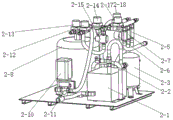
2, a device pipeline part, 2-1 vacuum machine, 2-2 sensor seat, 2-3 vacuum condenser, 2-4 vacuum condenser blow-down valve, 2-5 vacuum pumping electric valve, 2-6 exhaust electric valve, 2-7 oil injection electric valve, 2-8 fine filter, 2-9 blow-down valve, 2-10 oil pump, 2-11 coarse filter, 2-12 oil inlet valve, 2-13 oil outlet valve, 2-14 oil discharge bypass electric valve, 2-15 back pressure valve, 2-16 accessory sampling valve, 2-17 circulation selection electric valve, 2-18 accessory oil discharge electric valve;
3 transformer accessories; 4, an oil tank;
5 control part, 5-1 power circuit breaker, 5-2 vacuum machine frequency conversion controller, 5-3 oil pump frequency conversion controller, 5-4 control screen, 5-5 vacuum degree sensor, 5-6 fine filter pressure sensor and 5-7 back pressure valve pressure sensor.
Detailed Description
For a better understanding of the present invention, reference is made to the following detailed description taken in conjunction with the accompanying drawings in which:
a transformer accessory oil maintenance device comprises a box body 1, an equipment pipeline part 2 and a control part 5; the equipment pipeline part 2 and the control part 5 are arranged inside the box body 1 or on the box body 1;
as shown in figure 1, the box body 1 comprises a box shell 1-1, a bottom plate 1-2, rollers 1-3 and a cart handle 1-4; the bottom plate 1-2 is fixedly arranged at the bottom of the box shell 1-1; the roller 1-3 is arranged at the bottom of the bottom plate 1-2; the cart handle 1-4 is arranged on the box shell 1-1.
The box shell 1-1 is in a hollow cuboid shape; the reverse buckle is arranged on the bottom plate 1-2, and the framework support which is internally provided with the square tube and welded is fixedly connected with the bottom plate 1-2 by screws.
The bottom plate 1-2 is a square plate, and four square tubes are fixed at the lower part of the bottom plate and are used as reinforcing ribs 1-6 to increase the strength.
Four rollers 1-3 are arranged and are respectively arranged at four vertex angles of the bottom plate 1-2 and fixedly connected with the reinforcing ribs.
Two idler wheels 1-3 arranged at the front end of the bottom plate 1-2 are respectively universal wheels, and two idler wheels 1-3 arranged at the rear end of the bottom plate 1-2 are respectively fixed wheels.
The box body 1 also comprises a control panel 1-5, wherein the control panel 1-5 is a square plate, is obliquely arranged on the box shell 1-1 and is inclined by 30 degrees, is parallel to the sight of an operator, is provided with a square hole in the middle, is provided with a control screen 5-4, and is provided with a trolley handle 1-4 at two sides; the cart handles 1-4 are made of round pipes and are arranged at two sides of the control panel 1-5 for pushing the box body 1.
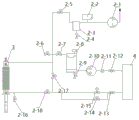
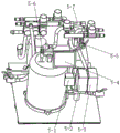
As shown in fig. 2, the equipment pipeline part 2 comprises a vacuum machine 2-1, a sensor seat 2-2, a vacuum condenser 2-3, a vacuum condenser blow-off valve 2-4, a vacuumizing electric valve 2-5, an exhaust electric valve 2-6, an oil injection electric valve 2-7, a fine filter 2-8, a blow-off valve 2-9, an oil pump 2-10, a coarse filter 2-11, an oil inlet valve 2-12, an oil outlet valve 2-13, an oil discharge bypass electric valve 2-14, a back pressure valve 2-15, an accessory sampling valve 2-16, a circulation selection electric valve 2-17 and an accessory oil discharge electric valve 2-18;
the control part 5 comprises a power supply circuit breaker 5-1, a vacuum machine variable frequency controller 5-2, an oil pump variable frequency controller 5-3, a control screen 5-4, a vacuum degree sensor 5-5, a fine filter pressure sensor 5-6 and a back pressure valve pressure sensor 5-7;
one end of the sensor seat 2-2 is connected with the vacuum machine 2-1, and the other end is connected with the vacuum condenser 2-3 and is used for installing a vacuum degree sensor 5-5; the vacuum machine 2-1 is used for vacuumizing the transformer accessory 3; the vacuum condenser 2-3 is used for condensing moisture brought out by the transformer accessory 3 during vacuum pumping and containing oil spilling generated during vacuum oil injection of the transformer accessory 3; the transformer accessories 3 are oil-filled groups and accessories of the transformer, generally comprise an oil filling port and an oil discharge port, and can be connected with the transformer through a pipeline.
The vacuum condenser 2-3, the vacuumizing electric valve 2-5 and the transformer accessory 3 are sequentially connected through a pipeline, and a condenser blow-down valve 2-4 is installed at the bottom of the vacuum condenser 2-3; the vacuumizing electric valve 2-5 is used for controlling the opening and closing of a vacuumizing pipeline; the condenser blow-down valve 2-4 is used for discharging condensed water and dirty oil of the vacuum condenser 2-3;
the exhaust electric valve 2-6 is connected in parallel with the pipeline connecting the vacuumizing electric valve 2-5 and the transformer accessory 3 and is used for exhausting and breaking vacuum of the vacuumizing pipeline;
the oil inlet valves 2 to 12 are connected with the oil tank 4; 2-12 parts of an oil inlet valve, 2-11 parts of a coarse filter, 2-10 parts of an oil pump, 2-8 parts of a fine filter and 2-7 parts of an oil injection electric valve are connected in sequence; a drain valve 2-9 is arranged at the bottom of the fine filter 2-8; the oil injection electric valve 2-7 is connected in parallel with a pipeline for connecting the vacuumizing electric valve 2-5 with the transformer accessory 3;
the oil inlet valves 2 to 12 are used for controlling the opening and closing of an oil inlet pipeline; the coarse filter 2-11 is used for pre-filtering coarser particle impurities in the oil to reduce the blockage of the fine filter; the oil pumps 2-10 are used for providing power for oil flow; a high-precision filter element is arranged in the fine filter 2-8 and is used for filtering impurities in the oil and absorbing water in the oil; the drain valve 2-9 is used for discharging impurities and dirty oil in the fine filter 2-8; the oil injection electric valves 2 to 7 are used for controlling the opening and the closing of an oil injection pipeline;
the oil outlet valves 2 to 13 are connected with the oil tank 4, and the oil outlet valves 2 to 13 are respectively connected with an oil discharge bypass electric valve 2 to 14 and a back pressure valve 2 to 15; the oil discharge bypass electric valve 2-14 and the back pressure valve 2-15 are respectively connected with the accessory oil discharge electric valve 2-18; the accessory oil discharge electric valve 2-18, the accessory sampling valve 2-16 and the transformer accessory 3 are sequentially connected through pipelines; the circulation selection electric valve 2-17 is respectively connected with the vacuumizing electric valve 2-5, the exhaust electric valve 2-6, the oil injection electric valve 2-7, the transformer accessory 3, the oil discharge bypass electric valve 2-14, the back pressure valve 2-15 and the accessory oil discharge electric valve 2-18; the oil outlet valve 2-13 is used for controlling the opening and closing of the oil outlet pipeline; the oil discharge bypass electric valve 2-14 is used for controlling a branch loop of an oil outlet pipeline, and oil flow can flow into the oil tank 4 without pressure by opening the oil discharge bypass electric valve 2-14; the back pressure valve 2-15 is used for controlling the conduction of an oil outlet pipeline when the oil drain bypass electric valve 2-14 is closed and the oil pressure reaches a preset value, and can establish the oil pressure when the oil drain bypass electric valve is closed and conduct when the oil pressure reaches a set value of the back pressure valve; the accessory sampling valves 2 to 16 are used for collecting oil samples and connected to oil outlets of the transformer accessories, and the oil samples are conveniently collected after the maintenance is finished so as to provide oil for testing; the circulation selection electric valves 2-17 are used for controlling whether oil flow passes through the transformer accessory 3 or not and communicating an oil inlet and an oil outlet of the transformer accessory, when the valve is closed, the oil circulation of the oil forms oil flow which passes through the oil flow internal circulation in the transformer accessory 3, and when the valve is opened, the oil circulation of the oil forms oil flow which does not pass through the oil flow external circulation in the transformer accessory 3; the accessory oil discharge electric valves 2-18 are used for controlling the opening or closing of an oil flow channel inside the transformer accessory 3.
The oil tank 4 is connected with the oil inlet pipeline and the oil outlet pipeline, is a container, stores transformer oil, can store new oil of the transformer, and can also store old oil discharged from the transformer, and the oil storage tank and the waste oil tank are the same container.
The power supply circuit breaker 5-1 is respectively connected with the vacuum machine variable frequency controller 5-2 and the oil pump variable frequency controller 5-3; a vacuum machine variable frequency controller 5-2, an oil pump variable frequency controller 5-3, a vacuum degree sensor 5-5, a fine filter pressure sensor 5-6 and a back pressure valve pressure sensor 5-7 are respectively connected with a control screen 5-4;
the power supply breaker 5-1 is connected with a 220V alternating current power supply and is used for providing power for the vacuum machine 2-1 and the oil pump 2-10;
the vacuum machine variable frequency controller 5-2 provides 220V alternating current voltage by the power circuit breaker 5-1, converts the voltage into 380V three-phase alternating current voltage to provide a power supply of the vacuum machine 2-1, and controls the output frequency by the control screen 5-4;
the oil pump frequency conversion controller 5-3 provides 220V alternating current voltage by the power circuit breaker 5-1, converts the voltage into 380V three-phase alternating current voltage to provide a power supply of the oil pump 2-10, and controls the output frequency by the control panel 5-4;
the control screen 5-4 is embedded in the middle of the control panel 1-5 of the box body 1, and the machine can work step by step or automatically work in the whole process;
the vacuum degree sensor 5-5 is a vacuum pressure sensor and is used for collecting a vacuum degree signal of the vacuum machine 2-1 and transmitting the vacuum degree signal to the control screen 5-4;
the fine filter pressure sensor 5-6 is a high-precision pressure sensor and is used for collecting the pressure inside the fine filter 2-9 and transmitting the pressure to the control screen 5-4, automatically judging the filter element blockage degree and warning the replacement of the filter element;
the backpressure valve pressure sensor 5-7 is a high-precision pressure sensor and is used for collecting the pressure value of the backpressure valve 2-15, transmitting the pressure value to the control screen 5-4, providing a pressure build-up value of static pressure oil circulation and adjusting the pressure value of the backpressure valve 2-15 according to the pressure build-up value;
and the control screen 5-4 receives signals of the vacuum degree sensor 5-5, the fine filter pressure sensor 5-6 and the back pressure valve pressure sensor 5-7, displays the signals on a screen, and controls the output frequencies of the vacuum machine variable frequency controller 5-2 and the oil pump variable frequency controller 5-3. The control screen 5-4 comprises a controller and a display screen, and the valves, the vacuum machine 2-1 and the opening boxes of the oil pumps 2-10 are controlled by the controller to be closed.
The use method of the transformer accessory oil maintenance device comprises the following steps:
s1: initial setting: when all valves are in a closed state, the oil injection valve and the oil discharge valve of the transformer accessory 3 are connected with reference to fig. 2, the oil inlet valve 2-12 is connected with the oil tank 4, the oil discharge valve 2-15 is connected with the oil tank 4, and the oil inlet valve 2-12 and the oil discharge valve 2-13 are opened.
S2: oil discharge of transformer accessories: and opening the electric exhaust valve 2-6, the electric accessory oil discharge valve 2-18 and the electric oil discharge bypass valve 2-14, naturally discharging transformer oil in the sleeve of the transformer accessory 3, and closing the electric exhaust valve 2-6, the electric accessory oil discharge valve 2-18 and the electric oil discharge bypass valve 2-14.
S3: cleaning the transformer accessories: opening the electric vacuum valve 2-5, starting the vacuum machine 2-1, stopping the vacuum machine 2-1 when the vacuum count value of the vacuum degree sensor 5-5 reaches a set value of-0.5 MPa, and closing the electric vacuum valve 2-5.
Opening the oil injection electric valve 2-7, starting the oil injection of the oil pump 2-10, stopping the oil injection of the oil pump 2-10 after the transformer accessory 3 is full of oil, closing the oil injection electric valve 2-7 until the standing time is met, opening the accessory oil discharge electric valve 2-18 and the oil discharge bypass electric valve 2-14, then opening the exhaust electric valve 2-6, naturally discharging oil, exhausting the transformer oil in the transformer accessory 3, and closing the exhaust electric valve 2-6, the accessory oil discharge electric valve 2-18 and the oil discharge bypass electric valve 2-14.
S4: vacuumizing the transformer accessory: and opening the vacuumizing electric valve 2-5, starting the vacuum machine 2-1, starting countdown after the vacuum count value of the vacuum degree sensor 5-5 meets the requirement, stopping vacuumizing by the vacuum machine 2-1 until the vacuumizing time is met, and closing the vacuumizing electric valve 2-5.
S5: vacuum oil injection of transformer accessories: the oil inlet pipe and the oil discharge pipe are connected with an oil tank 4, the vacuumizing electric valve 2-5 is opened, the vacuum machine 2-1 is started, when the vacuum count value of the vacuum degree sensor 5-5 meets the requirement, countdown is started until the vacuumizing time is met, the oil outlet valve 2-13, the oil discharge bypass electric valve 2-14 and the accessory oil discharge electric valve 2-18 are opened, after the transformer accessory 3 is full of oil, the oil outlet valve 2-13, the oil discharge bypass electric valve 2-14 and the accessory oil discharge electric valve 2-18 are closed, oil injection is stopped, the vacuum machine 2-1 stops vacuumizing, and the vacuumizing electric valve 2-5 is closed.
S6: static pressure oil circulation of transformer accessories: the oil inlet pipe and the oil discharge pipe are connected with the oil tank 4, the oil injection electric valve 2-7 is opened, the circulation selection electric valve 2-17 is opened, the oil pump 2-10 is started to continue oil injection, the back pressure valve 2-15 is opened, the countdown is started until the circulation time is met, the oil pump 2-10 is stopped, the oil injection electric valve 2-7 is closed, and the circulation selection electric valve 2-17 is closed.
S7: the transformer accessory conventional oil circulation, the oil inlet pipe and the oil discharge pipe are connected with the oil tank 4, the oil injection electric valve 2-7 is opened, the accessory oil discharge electric valve 2-18 and the oil discharge bypass electric valve 2-14 are opened, the oil pump 2-10 is started to continue oil injection, countdown is started until the circulation time is met, the oil pump 2-10 is stopped, the oil injection electric valve 2-7 is closed, and the accessory oil discharge electric valve 2-18 and the oil discharge bypass electric valve 2-14 are closed.
Each function in the using method can be automatically controlled in a single function mode, and can also be automatically controlled in a multifunctional integrated mode, and operation is convenient. Particularly, the control screen 5-4 is used for opening and closing various valves, the vacuum machine 2-1 and the oil pump 2-10.
The present invention is not limited to the above-described embodiments, which are merely preferred embodiments of the present invention, and the present invention is not limited thereto, and any modification, equivalent replacement, and improvement made within the spirit and principle of the present invention should be included in the protection scope of the present invention.
Claims (7)
1. The utility model provides a transformer annex oil affairs overhaul device which characterized in that: comprises a box body (1), an equipment pipeline part (2) and a control part (5); the equipment pipeline part (2) and the control part (5) are arranged in the box body (1) or on the box body (1); the equipment pipeline part (2) comprises a vacuum machine (2-1), a sensor seat (2-2), a vacuum condenser (2-3), a vacuum condenser blow-down valve (2-4), a vacuumizing electric valve (2-5), an exhaust electric valve (2-6), an oil injection electric valve (2-7), a fine filter (2-8), a blow-down valve (2-9), an oil pump (2-10), a coarse filter (2-11), an oil inlet valve (2-12), an oil outlet valve (2-13), an oil discharge bypass electric valve (2-14), a backpressure valve (2-15), an accessory sampling valve (2-16), a circulation selection electric valve (2-17) and an accessory oil discharge electric valve (2-18);
the control part (5) comprises a power supply circuit breaker (5-1), a vacuum machine variable frequency controller (5-2), an oil pump variable frequency controller (5-3), a control screen (5-4), a vacuum degree sensor (5-5), a fine filter pressure sensor (5-6) and a back pressure valve pressure sensor (5-7);
one end of the sensor seat (2-2) is connected with the vacuum machine (2-1), and the other end of the sensor seat is connected with the vacuum condenser (2-3) and is used for installing a vacuum degree sensor (5-5); the vacuum machine (2-1) is used for vacuumizing the transformer accessory (3); the vacuum condenser (2-3) is used for condensing moisture brought out by the transformer accessory (3) during vacuum pumping and containing oil spilling generated during vacuum oil injection of the transformer accessory (3);
the vacuum condenser (2-3), the vacuumizing electric valve (2-5) and the transformer accessory (3) are sequentially connected through a pipeline, and a condenser blow-down valve (2-4) is installed at the bottom of the vacuum condenser (2-3); the vacuumizing electric valve (2-5) is used for controlling the opening and closing of the vacuumizing pipeline; the condenser blow-down valve (2-4) is used for discharging condensed water and dirty oil of the vacuum condenser (2-3);
the exhaust electric valve (2-6) is connected in parallel to a pipeline connected with the vacuumizing electric valve (2-5) and the transformer accessory (3) and is used for exhausting and breaking vacuum of the vacuumizing pipeline;
the oil inlet valves (2-12) are connected with the oil tank (4); the oil inlet valve (2-12), the coarse filter (2-11), the oil pump (2-10), the fine filter (2-8) and the oil injection electric valve (2-7) are connected in sequence; a drain valve (2-9) is arranged at the bottom of the fine filter (2-8); the oil injection electric valve (2-7) is connected in parallel to a pipeline for connecting the vacuum pumping electric valve (2-5) with the transformer accessory (3);
the oil inlet valve (2-12) is used for controlling the opening and closing of an oil inlet pipeline; the coarse filter (2-11) is used for filtering impurities in the oil in advance; the oil pump (2-10) is used for providing power for oil flow; the fine filter (2-8) is used for filtering impurities in the oil and absorbing water in the oil; the blowdown valve (2-9) is used for discharging impurities and dirty oil in the fine filter (2-8); the oil filling electric valve (2-7) is used for controlling the opening and closing of an oil filling pipeline;
the oil outlet valves (2-13) are connected with the oil tank (4), and the oil outlet valves (2-13) are respectively connected with an oil discharge bypass electric valve (2-14) and a back pressure valve (2-15); the oil discharge bypass electric valve (2-14) and the back pressure valve (2-15) are respectively connected with the accessory oil discharge electric valve (2-18); the accessory oil discharge electric valve (2-18), the accessory sampling valve (2-16) and the transformer accessory (3) are sequentially connected through a pipeline; the circulation selection electric valve (2-17) is respectively connected with the vacuumizing electric valve (2-5), the exhaust electric valve (2-6), the oil injection electric valve (2-7), the transformer accessory (3), the oil discharge bypass electric valve (2-14), the backpressure valve (2-15) and the accessory oil discharge electric valve (2-18); the oil outlet valve (2-13) is used for controlling the opening and closing of an oil outlet pipeline; the oil discharge bypass electric valve (2-14) is used for controlling a branch loop of an oil outlet pipeline; the back pressure valve (2-15) controls the conduction of an oil outlet pipeline when the oil discharge bypass electric valve (2-14) is closed and the oil pressure reaches a preset value; the accessory sampling valves (2-16) are used for collecting oil samples; the circulation selection electric valve (2-17) is used for controlling whether oil flow passes through the transformer accessory (3); the accessory oil discharge electric valve (2-18) is used for controlling the opening or closing of an oil flow channel inside the transformer accessory (3);
the power circuit breaker (5-1) is respectively connected with the vacuum machine variable frequency controller (5-2) and the oil pump variable frequency controller (5-3); the vacuum machine variable frequency controller (5-2), the oil pump variable frequency controller (5-3), the vacuum degree sensor (5-5), the fine filter pressure sensor (5-6) and the back pressure valve pressure sensor (5-7) are respectively connected with the control screen (5-4);
the power supply circuit breaker (5-1) is connected with an alternating current power supply and is used for providing power for the vacuum machine (2-1) and the oil pump (2-10);
the vacuum machine variable frequency controller (5-2) is provided with alternating voltage by a power circuit breaker (5-1), and the output frequency is controlled by a control screen (5-4);
the oil pump variable frequency controller (5-3) is provided with alternating voltage by a power circuit breaker (5-1), and the output frequency is controlled by a control screen (5-4);
the control screen (5-4) is embedded on the box body (1);
the vacuum degree sensor (5-5) is used for collecting a vacuum degree signal of the vacuum machine (2-1) and transmitting the vacuum degree signal to the control screen (5-4);
the fine filter pressure sensor (5-6) is used for collecting the pressure inside the fine filter (2-9), transmitting the pressure to the control screen (5-4), automatically judging the filter element blockage degree and warning the replacement of the filter element;
the backpressure valve pressure sensor (5-7) is used for acquiring a pressure value of the backpressure valve (2-15), transmitting the pressure value to the control screen (5-4), providing a pressure build-up value of static pressure oil circulation, and adjusting the pressure value of the backpressure valve (2-15) according to the pressure build-up value;
and the control screen (5-4) receives signals of the vacuum degree sensor (5-5), the fine filter pressure sensor (5-6) and the back pressure valve pressure sensor (5-7), displays the signals on the screen, and controls the output frequencies of the vacuum machine variable frequency controller (5-2) and the oil pump variable frequency controller (5-3) at the same time.
2. The transformer accessory oil service maintenance device of claim 1, wherein: the box body (1) comprises a box shell (1-1), a bottom plate (1-2), rollers (1-3) and a cart handle (1-4);
the bottom plate (1-2) is fixedly arranged at the bottom of the box shell (1-1); the rollers (1-3) are arranged at the bottom of the bottom plate (1-2); the cart handle (1-4) is arranged on the case shell (1-1).
3. The transformer accessory oil service maintenance device of claim 2, wherein: the box shell (1-1) is in a hollow cuboid shape; the back-off is arranged on the bottom plate (1-2), and the inside is supported and fixed by a framework welded by square pipes.
4. The transformer accessory oil service maintenance device of claim 2, wherein: the bottom plate (1-2) is a square plate, and a square tube is fixed at the lower part of the bottom plate and is used as a reinforcing rib to increase the strength.
5. The transformer accessory oil service maintenance device of claim 4, wherein: the four rollers (1-3) are respectively arranged at the four top corners of the bottom plate (1-2) and fixedly connected with the reinforcing ribs.
6. The transformer accessory oil service maintenance device of claim 5, wherein: two idler wheels (1-3) arranged at the front end of the bottom plate (1-2) are respectively universal wheels, and two idler wheels (1-3) arranged at the rear end of the bottom plate (1-2) are respectively fixed wheels.
7. The use method of the transformer accessory oil service overhaul device as claimed in claim 1, wherein the method comprises the following steps: the method comprises the following specific steps:
s1: initial setting: when all valves are in a closed state, the device is connected with an oil filling port and an oil discharging port of a transformer accessory (3), an oil inlet valve (2-12) is connected with an oil tank (4), an oil outlet valve (2-15) is connected with the oil tank (4), and the oil inlet valve (2-12) and the oil outlet valve (2-13) are opened;
s2: oil discharge of transformer accessories: opening the exhaust electric valve (2-6), the accessory oil discharge electric valve (2-18) and the oil discharge bypass electric valve (2-14), naturally draining transformer oil in a sleeve of the transformer accessory (3), and closing the exhaust electric valve (2-6), the accessory oil discharge electric valve (2-18 and the oil discharge bypass electric valve (2-14);
s3: cleaning the transformer accessories: opening the vacuumizing electric valve (2-5), starting the vacuum machine (2-1), stopping vacuumizing the vacuum machine (2-1) when the vacuum count value of the vacuum degree sensor (5-5) reaches a set value, and closing the vacuumizing electric valve (2-5);
opening an oil injection electric valve (2-7), starting an oil pump (2-10) for injecting oil, stopping injecting the oil into the oil pump (2-10) after the transformer accessory (3) is full of oil, closing the oil injection electric valve (2-7), opening an accessory oil discharge electric valve (2-18) and an oil discharge bypass electric valve (2-14) until the standing time is met, then opening an exhaust electric valve (2-6), naturally discharging the oil, exhausting the transformer oil in the transformer accessory (3), and closing the exhaust electric valve (2-6), the accessory oil discharge electric valve (2-18) and the oil discharge bypass electric valve (2-14);
s4: vacuumizing the transformer accessory: opening the vacuumizing electric valve (2-5), starting the vacuum machine (2-1), starting countdown until the vacuum count value of the vacuum degree sensor (5-5) meets the requirement, stopping vacuumizing the vacuum machine (2-1) until the vacuumizing time is met, and closing the vacuumizing electric valve (2-5);
s5: vacuum oil injection of transformer accessories: the oil inlet pipe and the oil outlet pipe are connected with an oil tank (4), a vacuumizing electric valve (2-5) is opened, a vacuum machine (2-1) is started, when the vacuum count value of a vacuum degree sensor (5-5) meets the requirement, countdown is started until the vacuumizing time is met, an oil outlet valve (2-13), an oil outlet bypass electric valve (2-14) and an accessory oil discharging electric valve (2-18) are opened, after a transformer accessory (3) is full of oil, the oil outlet valve (2-13), the oil outlet bypass electric valve (2-14) and the accessory oil discharging electric valve (2-18) are closed, oil injection is stopped, the vacuum machine (2-1) stops vacuumizing, and the vacuumizing electric valve (2-5) is closed;
s6: static pressure oil circulation of transformer accessories: the oil inlet pipe and the oil outlet pipe are connected with an oil tank (4), an oil injection electric valve (2-7) is opened, a circulation selection electric valve (2-17) is opened, an oil pump (2-10) is started to continue oil injection, a back pressure valve (2-15) is opened, countdown is started until the circulation time is met, the oil pump (2-10) is stopped, the oil injection electric valve (2-7) is closed, and the circulation selection electric valve (2-17) is closed;
s7: the method comprises the steps that the transformer accessory conventional oil circulates, an oil inlet pipe and an oil discharge pipe are connected with an oil tank (4), an oil injection electric valve (2-7) is opened, an accessory oil discharge electric valve (2-18) and an oil discharge bypass electric valve (2-14) are opened, oil injection of the oil pump (2-10) is continued, countdown is started until the circulation time is met, the oil pump (2-10) is stopped, the oil injection electric valve (2-7) is closed, and the accessory oil discharge electric valve (2-18) and the oil discharge bypass electric valve (2-14) are closed.
Priority Applications (1)
| Application Number | Priority Date | Filing Date | Title |
|---|---|---|---|
| CN202011177500.4A CN112382471A (en) | 2020-10-29 | 2020-10-29 | Transformer accessory oil maintenance device and use method thereof |
Applications Claiming Priority (1)
| Application Number | Priority Date | Filing Date | Title |
|---|---|---|---|
| CN202011177500.4A CN112382471A (en) | 2020-10-29 | 2020-10-29 | Transformer accessory oil maintenance device and use method thereof |
Publications (1)
| Publication Number | Publication Date |
|---|---|
| CN112382471A true CN112382471A (en) | 2021-02-19 |
Family
ID=74576361
Family Applications (1)
| Application Number | Title | Priority Date | Filing Date |
|---|---|---|---|
| CN202011177500.4A Withdrawn CN112382471A (en) | 2020-10-29 | 2020-10-29 | Transformer accessory oil maintenance device and use method thereof |
Country Status (1)
| Country | Link |
|---|---|
| CN (1) | CN112382471A (en) |
-
2020
- 2020-10-29 CN CN202011177500.4A patent/CN112382471A/en not_active Withdrawn
Similar Documents
| Publication | Publication Date | Title |
|---|---|---|
| CN107443788A (en) | A kind of automatic block obtaining maching structure of house refuse briquetting machine | |
| CN208718937U (en) | A kind of jet water pump with filtering function | |
| CN201246367Y (en) | Movable hydraulic oil multilevel circulation filtering device | |
| CN213935871U (en) | Transformer accessory oil affairs overhaul device | |
| CN112382471A (en) | Transformer accessory oil maintenance device and use method thereof | |
| CN104368561B (en) | Cleaning device for integral driving generator part accessory and cleaning method of integral driving generator part accessory | |
| CN112218508A (en) | Electric power detection device cooling equipment with cooling and dust removing functions | |
| CN104550099B (en) | Aircarrier aircraft kitchen water boiling device automatic cleaning system | |
| CN214698615U (en) | Integrated movable oil filtering and oiling equipment for hydraulic mechanism | |
| CN211777875U (en) | Integrated negative pressure vacuum system | |
| CN107497227A (en) | A kind of environment-friendly type aluminium alloy smelting cleaner | |
| CN212476091U (en) | Automatic coolant replacing device | |
| CN209604301U (en) | A kind of improved centrifugal air compressor room power saving apparatus | |
| CN208138252U (en) | One kind turning over roller pump station device | |
| CN116002603B (en) | Full-closed intelligent receiving and discharging device for liquid dangerous chemicals tank car | |
| CN216950333U (en) | Oil gas field development water injection flow controlling means | |
| CN220176252U (en) | Leak protection liquid device of vacuum oil filter | |
| CN114197587B (en) | Non-negative pressure water supply equipment | |
| CN110624702A (en) | Intelligent centrifugal oil purifier | |
| CN214940685U (en) | Secondary water supply equipment | |
| CN109520369A (en) | Turbo-generator Set Cooling Tubes of Condenser ball cleaning apparatus | |
| CN209476854U (en) | A kind of Converter Station Valve cooling system main filter exempts from demolition clean device | |
| CN209650148U (en) | One kind being used for lodging vehicle water route current divider | |
| CN217002464U (en) | Multifunctional mobile hydraulic workstation | |
| CN217129943U (en) | Suction inlet structure for submersible oil electric pump |
Legal Events
| Date | Code | Title | Description |
|---|---|---|---|
| PB01 | Publication | ||
| PB01 | Publication | ||
| SE01 | Entry into force of request for substantive examination | ||
| SE01 | Entry into force of request for substantive examination | ||
| WW01 | Invention patent application withdrawn after publication |
Application publication date: 20210219 |
|
| WW01 | Invention patent application withdrawn after publication |