Preparation method of graphite-silicon-based lithium ion battery negative electrode material and product thereof
Technical Field
The invention relates to the technical field of lithium ion battery cathode materials, in particular to a preparation method of a graphite-silicon-based lithium ion battery cathode material and a product thereof.
Background
Lithium ion batteries are currently widely used in portable electronic devices, electric vehicles and hybrid vehiclesAnd the like. In order to meet the increasing market demand, battery technology is rapidly developing with the effort of improving manufacturing processes and combining up-to-date research efforts with applications, resulting in a significant increase in the energy density of lithium ion batteries. In this process, silicon is considered one of the most promising next-generation anode materials due to its theoretical capacity (-3579 mAhg)-1) Almost commercial graphite negative electrode (-372 mAhg)-1) Ten times higher than the anode material of the currently known highest lithium ion battery. However, there are many obstacles to the commercial value of silicon negative electrodes due to the huge volume expansion of silicon during lithium intercalation and its poor conductivity.
At present, the negative electrode material with commercial prospect is a graphite-silicon-based composite material, however, the specific capacity of the traditional graphite-silicon-based composite negative electrode is always limited because when graphite is compounded with silicon, silicon always coats the outer surface of the graphite, when the silicon content reaches a certain amount, a large amount of silicon particles are gathered on the surface of the graphite, and at the moment, the volume expansion effect is rapidly enhanced, so that huge capacity decay is caused. Meanwhile, the silicon particles tightly coated on the outer surface of the graphite reduce the overall conductivity of the electrode material, and the graphite serving as the core is difficult to obtain effective electric contact, so that the charge and discharge performance of the electrode material is also inhibited. Therefore, there is a need to develop a novel graphite-silicon-based composite material and a preparation process thereof.
Disclosure of Invention
Aiming at the problems in the prior art, the invention discloses a preparation method of a graphite-silicon-based lithium ion battery cathode material, and the prepared cathode material has the first reversible capacity of more than 800mAh/g and the capacity retention rate of more than 88% after 100 charge-discharge cycles, and is expected to be widely applied in the field of lithium ion batteries.
The specific technical scheme is as follows:
a preparation method of a graphite-silicon-based lithium ion battery negative electrode material comprises the following steps:
(1) placing a graphite material in corrosive gas for heat treatment to obtain hollow graphite, and controlling the corrosion degree D of the hollow graphite to be 20-40%;
the corrosive gas is selected from carbon dioxide and/or air;
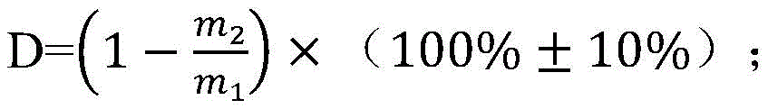
the corrosion degree D of the hollow graphite is as follows:
in the formula, m1G, the mass of the graphite material before the corrosion reaction; m is2G is the mass of the graphite material remaining after the corrosion reaction;
(2) and (2) placing the hollow graphite prepared in the step (1) in a silicon-based gaseous precursor for chemical vapor deposition to obtain the graphite-silicon-based lithium ion battery cathode material.
According to the preparation process disclosed by the invention, firstly, a graphite material is subjected to hollowing treatment by a gas etching method, so that not only is graphite on the surface corroded, but also a channel for silicon to enter the interior of the graphite is opened, and the graphite in the interior is corroded to obtain a uniform porous-macroporous structure; and through further chemical vapor deposition, the silicon particles are uniformly embedded in the inner layer gaps of the hollow graphite, the dispersibility of the silicon particles is good, the hollow graphite simultaneously serves as an excellent buffer body of the silicon particles, and the volume expansion and contraction of the silicon material during lithium intercalation and deintercalation are effectively inhibited.
In the invention, the distribution condition of silicon in graphite is the key of whether the graphite-silicon-based lithium ion battery cathode material can obtain high reversible capacity and cycle stability at the same time. Further tests show that the distribution condition of silicon in the graphite base material is directly related to the internal pore structure of the graphite base material, and high first reversible capacity and cycle stability can be ensured only when the corrosion degree D of the hollow graphite is controlled within 20-40%. When the degree of corrosion D is too small or too large, a significant decrease in capacity retention rate results.
Further preferably, the corrosion degree D of the hollow graphite is controlled to be 30-40%, tests show that the corrosion degree D is controlled to be in a further preferable range, and the prepared negative electrode material is higher in first reversible capacity and cycling stability.
In fact, in the preparation method of the invention, the corrosion degree D of the hollow graphite is controllable. Specifically, parameters such as the temperature of the heat treatment, the flow rate of the corrosive gas, the reaction duration and the like can be optimized.
In the step (1):
when the corrosive gas is selected from carbon dioxide, tests show that the heat treatment temperature is too low, such as 800 ℃, the reaction speed is very slow, and the pore diameter of the product is not obviously changed; the heat treatment temperature is too high, such as 1400 ℃, the corrosion of the product is serious, the surface damage is obvious, the structure collapses, and the hollow graphite with a complete structure is difficult to obtain. Preferably, the temperature of the heat treatment is 1000-1200 ℃.
Preferably, the time of the heat treatment is 0.5-15 h. The reaction time is too short, and the change of the internal pore diameter is not obvious enough; the time is too long, the quality loss of the graphite is too large, and the yield is too low. Generally, as the heat treatment temperature increases, the heat treatment time is shortened accordingly.
Further tests show that the internal pore structure of the hollowed graphite is related to the intensity of heat treatment reaction, and an inner pore structure with more reasonable pore size and more uniform distribution can be obtained under a milder reaction condition.
Preferably, when carbon dioxide is used as corrosive gas, the temperature of the heat treatment is 1000-1100 ℃ and the time is 3-10 h.
When the corrosive gas is selected from air, the temperature of the heat treatment is not higher than 800 ℃. Likewise, the temperature of the heat treatment is selected in a manner similar to that described above; the heat treatment temperature is too low, and the product does not obtain a porous structure; the heat treatment temperature is too high, and the corrosion of products is serious; in both cases, porous graphite having a high specific surface area cannot be obtained.
Preferably, when air is used as corrosive gas, the temperature of the heat treatment is 600-700 ℃, and the time is 3-10 hours.
Preferably, the flow rate of the etching gas is 100-5000 sccm. Tests show that when the flow rate of the corrosive gas exceeds 5000sccm, the product is seriously corroded due to the excessively high corrosion rate, and the reaction controllability is poor. When the flow rate of the etching gas is less than 100sccm, the reaction time is long, the loss of equipment is large, and the cost control in large-scale production is not facilitated.
Preferably, the heat treatment process is carried out in a rotary tube furnace, and the rotating speed is controlled to be 1-10 rpm; at the optimized rotating speed, the hollow graphite with more uniform internal pore size distribution can be prepared.
Preferably, the temperature rise is carried out in a protective gas environment before the heat treatment process. The protective gas is selected from nitrogen, argon and the like. Further preferably, the temperature rise rate of the heat treatment is 2.0 to 10.0 ℃/min.
In the step (1), the graphite material is selected from natural graphite and/or artificial graphite. The preparation process of the invention is not only suitable for natural graphite, but also suitable for artificial graphite.
The natural graphite includes natural spherical graphite, natural flake graphite, and the like; the artificial graphite comprises flake artificial graphite and spheroidal artificial graphite.
Preferably, the graphite material is selected from natural graphite, not only because the natural graphite is low in price, but also because the preparation method has more remarkable improvement on the electrical property of the natural graphite.
Further preferably, the graphite material is selected from natural spherical graphite, and tests show that the final negative electrode material prepared by using the natural spherical graphite has better electrical property compared with other natural graphite.
In the step (2):
the gaseous precursor of the silicon base is selected from Silane (SiH)4) Mixed gas with inert gas; the inert gas is selected from argon, helium, and the like. Preferably, the gaseous precursor of silicon base is selected from a mixed gas of silane and argon.
Experiments show that the volume fraction of silane in the mixed gas can influence the uniformity and the reaction rate of vapor deposition reaction, and further influence the distribution condition of silicon particles on the graphite surface. When the silane content is too high, the reaction is violent, silicon particles deposited on the surface of graphite agglomerate, and the cycle retention rate of the finally prepared cathode material is obviously reduced. Preferably, the volume fraction of silane in the mixed gas is 1-10%.
Preferably, the flow rate of the silicon-based gaseous precursor is 50-1000 sccm.
In the invention, the temperature of chemical vapor deposition influences the decomposition rate of silane, so that the proportion of free silicon and attached silicon in a reaction product is influenced, the deposition rate of silicon on the graphite surface and the particle size of the reaction product are also influenced, and in order to ensure higher output benefit, the temperature of chemical vapor deposition is preferably 450-650 ℃, and the time is preferably 0.5-10 h.
Further preferably:
in the mixed gas, the volume fraction of silane is 3-5%;
the flow rate of the silicon-based gaseous precursor is 100-1000 sccm;
the temperature of the chemical vapor deposition is 500-550 ℃, and the time is 3-6 h.
Experiments show that in the cathode material prepared by adopting the preferable process parameters in the chemical vapor deposition in the step (2), the deposition rate and deposition uniformity of silicon on the graphite surface and the size of deposited silicon particles are moderate, and the mass fraction of silicon in the cathode material is controlled to be 15-20 wt%. The prepared cathode material can reach 800mAh g-1The capacity retention rate after 100 cycles is more than 88% in the above first reversible specific capacity.
Still more preferably, in step (1):
the corrosion degree D of the hollow graphite is controlled to be 30-40%;
the graphite material is selected from natural spherical graphite;
experiments show that the prepared negative electrode material has higher first reversible capacity and cycle stability.
Preferably, the chemical vapor deposition process is carried out in a rotary tube furnace, and the rotating speed is controlled to be 1-10 rpm. Before chemical vapor deposition, the temperature needs to be raised in a protective gas environment, and preferably, the temperature raising speed of the heat treatment is 2.0-10.0 ℃/min.
The invention also discloses the graphite-silicon-based lithium ion battery cathode material prepared by the method, which has an embedded composite core-shell structure, the silicon nanoparticles are embedded in the inner layer gaps of the hollow graphite to form a core, and the shell is uniformly distributed silicon nanoparticles.
The silicon nanoparticles have a particle size of 50-300 nm and are distributed on the outer surface of the hollowed graphite in a small-size and uniformly dispersed state.
The specific capacity of the graphite-silicon-based lithium ion battery negative electrode material depends on the mass fraction of silicon, the larger the proportion of silicon, the higher the specific capacity of the material, however, the too high content of silicon is difficult to avoid severe volume expansion caused by the massive aggregation of silicon particles, and preferably, the silicon content in the graphite-silicon-based lithium ion battery negative electrode material is 1-30 wt%; further preferably 15 to 20 wt%.
Compared with the prior art, the invention has the following advantages:
the invention discloses a preparation method of a graphite-silicon-based lithium ion battery cathode material, which is characterized in that one-step pretreatment is added before gas phase coating of silicon, the internal pore structure of graphite is adjusted by a gas phase corrosion method, no impurity is introduced, the product purity is high, and the modification effect is good; the deposition of silicon in subsequent reaction is more uniform by regulating and controlling the corrosion degree D, the silicon particles are uniformly embedded in the graphite inner layer, the volume expansion of silicon during lithium embedding is relieved by utilizing the pores between the graphite sheet layers, and meanwhile, the thickness of the silicon layer on the surface of the graphite particles is controlled, so that the conductivity of the electrode material is effectively increased, and the high-performance graphite-silicon-based composite anode material is favorably obtained. The capacity retention rate of the graphite-silicon-based negative electrode material prepared by the method after 100 cycles is still kept above 88%, and the best capacity can be above 92%, and the specific capacity can be stabilized at 850mA h g-1Therefore, the lithium ion battery is expected to be widely applied in the field of lithium ion batteries.
Drawings
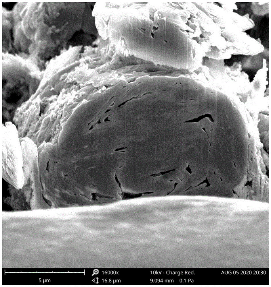
Fig. 1 is a cross-sectional Scanning Electron Microscope (SEM) picture of the graphite-silicon-based composite anode material prepared in example 1;
fig. 2 is a Scanning Electron Microscope (SEM) picture of the graphite-silicon-based composite anode material prepared in example 1;
fig. 3 is an XRD pattern of the graphite-silicon-based composite anode material prepared in example 1;
fig. 4 is a graph comparing impedances of half cells assembled with anode materials prepared in example 1 and comparative example 1, respectively;
FIG. 5 is a cross-sectional Scanning Electron Microscope (SEM) picture of the voided graphite prepared in comparative example 2;
FIG. 6 is a cross-sectional Scanning Electron Microscope (SEM) picture of the voided graphite prepared in comparative example 3;
FIG. 7 is a cross-sectional Scanning Electron Microscope (SEM) picture of the voided graphite prepared in comparative example 4;
fig. 8 is a Scanning Electron Microscope (SEM) picture of the graphite-silicon-based composite anode material prepared in example 4;
fig. 9 is a Scanning Electron Microscope (SEM) picture of the silicon-graphite anode material prepared in comparative example 5.
Detailed Description
The present invention is further illustrated by the following specific examples, but the scope of the present invention is not limited to the following examples.
Example 1
100g of natural spherical graphite is taken as a raw material and placed in a rotary tube furnace for heat treatment, the heating rate is 10 ℃/min under the protection of argon, the stable rotating speed is 3rpm, the reaction temperature is 1000 ℃, the flow of carbon dioxide is set to be 1000sccm after the temperature is stable, and the reaction time is 5 hours. The obtained graphite has 23% corrosion degree and average pore diameter of 734nm, and is in hollow structure.
Taking 50g of graphite subjected to hollowing treatment as a raw material, placing the graphite in a rotary tube furnace for vapor deposition, heating at a rate of 10 ℃/min under the protection of argon, stabilizing the rotating speed at 3rpm, reacting at a temperature of 500 ℃, introducing silane-argon mixed gas (wherein the volume fraction of silane is 5%) after the temperature is stabilized, setting the flow at 500sccm, and reacting for 6 hours to prepare the graphite-silicon-based composite negative electrode material.
Fig. 1 is a cross-sectional Scanning Electron Microscope (SEM) image of the graphite-silicon-based composite anode material prepared in this embodiment, and it can be observed from the image that silicon nanoparticles are embedded between graphite layers to form an embedded composite core, the silicon nanoparticles are uniformly distributed, and pores are reserved inside the graphite to reserve a space for the volume expansion of silicon during lithium intercalation, so as to alleviate a part of the volume expansion.
Fig. 2 is a Scanning Electron Microscope (SEM) image of the graphite-silicon-based composite negative electrode material prepared in this example, and it is observed that silicon nanoparticles deposited on the graphite surface are uniformly dispersed, and the particle size is about 100 nm.
Fig. 3 is an XRD pattern of the graphite-silicon-based composite anode material prepared in this example, from which strong diffraction peaks of graphite and silicon can be observed.
Comparative example 1
50g of natural spherical graphite is taken as a raw material and placed into a rotary tube furnace for vapor deposition, the heating rate is 10 ℃/min under the argon protection atmosphere, the stable rotating speed is 3rpm, the reaction temperature is 500 ℃, silane-argon mixed gas (the volume fraction of silane is 5%) is introduced after the temperature is stable, the flow is set to 1000sccm, and the reaction time is 5 hours. The obtained silicon-graphite composite negative electrode material.
Fig. 4 is an impedance comparison graph of half cells assembled with the negative electrode materials prepared in example 1 and comparative example 1, respectively, and it can be seen from observation that the graphite subjected to the hollowing treatment is beneficial to uniform distribution of silicon, so that the overall conductivity is significantly improved.
Example 2
200g of natural spherical graphite serving as a raw material is placed in a rotary tube furnace for heat treatment, the heating rate is 10 ℃/min under the protection of argon, the stable rotating speed is 5rpm, the reaction temperature is 700 ℃, the flow of introduced air is set to be 1000sccm after the temperature is stable, and the reaction time is 8 hours. The obtained graphite has a corrosion degree of 38%, an average pore diameter of 1049nm and a hollow structure.
Taking 50g of graphite subjected to hollowing treatment as a raw material, placing the graphite in a rotary tube furnace for vapor deposition, heating at a rate of 10 ℃/min under the protection of argon, stabilizing the rotating speed at 3rpm, reacting at a temperature of 500 ℃, introducing silane-argon mixed gas (wherein the volume fraction of silane is 3%), setting the flow at 1000sccm, and reacting for 4 hours to prepare the graphite-silicon-based composite anode material.
Comparative example 2
200g of natural spherical graphite serving as a raw material is placed into a rotary tube furnace for heat treatment, the heating rate is 10 ℃/min under the protection of argon, the stable rotating speed is 5rpm, the reaction temperature is 900 ℃, the flow of air introduced after the temperature is stable is set to be 5000sccm, and the reaction time is 1 h. The graphite obtained had a degree of corrosion of 38% and an average pore diameter of 1859 nm.
And (2) taking 50g of treated graphite as a raw material, placing the raw material into a rotary tube furnace for vapor deposition, heating at a rate of 10 ℃/min under the protection of argon, stabilizing the rotating speed at 3rpm, reacting at a temperature of 500 ℃, introducing silane-argon mixed gas (wherein the volume fraction of silane is 3%), setting the flow at 1000sccm, and reacting for 5 hours to prepare the graphite-silicon-based composite anode material.
FIG. 5 is a Scanning Electron Microscope (SEM) cross-sectional view of the voided graphite prepared in this comparative example; it can be seen from the figure that in the rough etching mode, the internal pore diameter of graphite is not uniformly distributed, and the large pore and small pore are greatly different, which is not beneficial to the uniform deposition of silicon.
Comparative example 3
The preparation process was the same as in example 2 except that the etching reaction time was shortened to 2 hours. The obtained graphite has a degree of corrosion of 15% and an average pore diameter of 368 nm.
Fig. 6 is a Scanning Electron Microscope (SEM) cross-sectional image of the voided graphite prepared in this comparative example, from which it can be seen that the inner pores are smaller and the pore structure inside is not effectively opened due to the lower degree of corrosion.
Comparative example 4
The preparation process was the same as in example 2, except that the etching reaction time was extended to 12 hours. The obtained graphite had a degree of corrosion of 53% and an average pore diameter of 2131 nm.
FIG. 7 is a Scanning Electron Microscope (SEM) cross-sectional view of the voided graphite prepared in this comparative example; it can be seen from the figure that the inner pores are larger due to the larger degree of corrosion, but the structural stability is reduced, and the structural stability is difficult to maintain during the subsequent lithium intercalation process of silicon deposition.
Example 3
50g of natural crystalline flake graphite is placed in a rotary tube furnace for heat treatment, the heating rate is 10 ℃/min under the protection of argon, the reaction temperature is 1100 ℃, the flow of carbon dioxide is set to be 200sccm after the temperature is stable, and the reaction time is 5 h. The obtained graphite has the corrosion degree of 38.9 percent and the average pore diameter of 1.21 mu m, and the spacing between graphite sheets is increased by observing scanning electron micrographs before and after reaction.
And (2) placing 30g of graphite subjected to hollowing treatment as a raw material into a rotary tube furnace for vapor deposition, heating at the rate of 10 ℃/min under the argon protection atmosphere, reacting at the temperature of 500 ℃, introducing a silane-argon mixed gas (wherein the volume fraction of silane is 10%), setting the flow rate to be 500sccm, and reacting for 6h to prepare the graphite-silicon-based composite negative electrode material.
Example 4
50g of flake artificial graphite is taken as a raw material and placed in a rotary tube furnace for heat treatment, the heating rate is 8 ℃/min under the nitrogen protection atmosphere, the stable rotating speed is 5rpm, the reaction temperature is 1050 ℃, the flow of carbon dioxide is set to be 1000sccm after the temperature is stable, and the reaction time is 3 hours. The obtained graphite has the corrosion degree of 28.17 percent and the average pore diameter of 1.89 mu m, and the spacing between graphite sheets is increased by observing scanning electron micrographs before and after reaction.
Taking 10g of graphite subjected to hollowing treatment as a raw material, placing the graphite in a rotary tube furnace for vapor deposition, heating at a rate of 8 ℃/min under the protection of nitrogen, stabilizing the rotating speed at 5rpm, reacting at 550 ℃, introducing silane-argon mixed gas (wherein the volume fraction of silane is 3%) after the temperature is stabilized, setting the flow rate at 100sccm, and reacting for 3 hours to prepare the graphite-silicon-based composite anode material.
Fig. 8 is a Scanning Electron Microscope (SEM) image of the silicon-graphite negative electrode material prepared in this example, and it can be observed that silicon is uniformly deposited on the graphite surface in the form of nanoparticles, and the silicon is tightly compounded and uniformly distributed.
Example 5
100g of spheroidal artificial graphite is taken as a raw material and placed in a rotary tube furnace for heat treatment, the heating rate is 8 ℃/min under the nitrogen protection atmosphere, the reaction temperature is 600 ℃, the flow of introduced air is set to be 1000sccm after the temperature is stable, and the reaction time is 5 h. The obtained graphite has 21.14% of corrosion degree and 517nm of average pore diameter, and meets the hollowing requirement.
Taking 50g of graphite subjected to hollowing treatment as a raw material, placing the graphite in a porcelain boat, placing the porcelain boat in a tubular furnace for vapor deposition, heating at the temperature rising rate of 8 ℃/min under the nitrogen protection atmosphere, reacting at the temperature of 550 ℃, introducing silane-argon mixed gas (wherein the volume fraction of silane is 5%), setting the flow rate to be 1000sccm, and reacting for 6 hours to prepare the graphite-silicon-based composite anode material.
Comparative example 5
The preparation process was the same as in example 5, except that a silane-argon mixture gas (in which the volume fraction of silane was 25%) was introduced while performing vapor deposition, the flow rate was set to 500sccm, and the reaction time was 6 hours.
Fig. 9 is a Scanning Electron Microscope (SEM) image of the graphite-silicon-based composite negative electrode material prepared in the present comparative example, and it can be observed that a large number of free silicon particles are attached to the graphite surface, and the silicon particles are spherical and have a particle size of about 0.5 to 1 μm.
A certain mass (5mg) of the graphite-silicon-based composite negative electrode material prepared in each example and each comparative example was weighed and dissolved in a sufficient amount of sodium hydroxide solution, and after dilution, ICP (inductively coupled plasma spectroscopy) was performed and the mass fraction of silicon was measured and calculated, and the test results are shown in table 1.
The mass fraction w of silicon is:
in the formula, ICP is the concentration of the diluted solution in ppm.
TABLE 1
| Numbering
|
ICP results (ppm)
|
Mass fraction of silicon (%)
|
| Example 1
|
7.735
|
15.47
|
| Example 2
|
9.29
|
18.58
|
| Example 3
|
7.66
|
15.32
|
| Example 4
|
9.735
|
19.47
|
| Example 5
|
7.665
|
15.33
|
| Comparative example 1
|
7.76
|
15.52
|
| Comparative example 2
|
9.22
|
18.44
|
| Comparative example 3
|
9.105
|
18.21
|
| Comparative example 4
|
9.235
|
18.47
|
| Comparative example 5
|
7.605
|
15.21 |
The composite negative electrode materials respectively prepared in each example and comparative example were assembled into a half cell to perform a cycle performance test, in which the cell coated with the graphite-silicon based composite negative electrode material was used as a positive electrode and a lithium sheet was used as a counter electrode. The proportion of each component in the pole piece is as follows: 88% of negative electrode material, 10% of binder CMC and 2% of conductive agent SP; the loading of the active material on the pole piece is 1.5mg/cm2. The following examples and comparative examples assemble a half cell in the same manner.
The current density used for the test was 0.2C and the electrochemical test results are shown in table 2 below.
TABLE 2