CN112360112A - Painting device for building - Google Patents
Painting device for building Download PDFInfo
- Publication number
- CN112360112A CN112360112A CN202011215317.9A CN202011215317A CN112360112A CN 112360112 A CN112360112 A CN 112360112A CN 202011215317 A CN202011215317 A CN 202011215317A CN 112360112 A CN112360112 A CN 112360112A
- Authority
- CN
- China
- Prior art keywords
- painting
- negative pressure
- rod
- rotating shaft
- fixedly arranged
- Prior art date
- Legal status (The legal status is an assumption and is not a legal conclusion. Google has not performed a legal analysis and makes no representation as to the accuracy of the status listed.)
- Withdrawn
Links
Images


Classifications
-
- E—FIXED CONSTRUCTIONS
- E04—BUILDING
- E04F—FINISHING WORK ON BUILDINGS, e.g. STAIRS, FLOORS
- E04F21/00—Implements for finishing work on buildings
- E04F21/02—Implements for finishing work on buildings for applying plasticised masses to surfaces, e.g. plastering walls
- E04F21/06—Implements for applying plaster, insulating material, or the like
- E04F21/08—Mechanical implements
-
- A—HUMAN NECESSITIES
- A47—FURNITURE; DOMESTIC ARTICLES OR APPLIANCES; COFFEE MILLS; SPICE MILLS; SUCTION CLEANERS IN GENERAL
- A47L—DOMESTIC WASHING OR CLEANING; SUCTION CLEANERS IN GENERAL
- A47L11/00—Machines for cleaning floors, carpets, furniture, walls, or wall coverings
- A47L11/38—Machines, specially adapted for cleaning walls, ceilings, roofs, or the like
-
- A—HUMAN NECESSITIES
- A47—FURNITURE; DOMESTIC ARTICLES OR APPLIANCES; COFFEE MILLS; SPICE MILLS; SUCTION CLEANERS IN GENERAL
- A47L—DOMESTIC WASHING OR CLEANING; SUCTION CLEANERS IN GENERAL
- A47L11/00—Machines for cleaning floors, carpets, furniture, walls, or wall coverings
- A47L11/40—Parts or details of machines not provided for in groups A47L11/02 - A47L11/38, or not restricted to one of these groups, e.g. handles, arrangements of switches, skirts, buffers, levers
- A47L11/4013—Contaminants collecting devices, i.e. hoppers, tanks or the like
-
- A—HUMAN NECESSITIES
- A47—FURNITURE; DOMESTIC ARTICLES OR APPLIANCES; COFFEE MILLS; SPICE MILLS; SUCTION CLEANERS IN GENERAL
- A47L—DOMESTIC WASHING OR CLEANING; SUCTION CLEANERS IN GENERAL
- A47L11/00—Machines for cleaning floors, carpets, furniture, walls, or wall coverings
- A47L11/40—Parts or details of machines not provided for in groups A47L11/02 - A47L11/38, or not restricted to one of these groups, e.g. handles, arrangements of switches, skirts, buffers, levers
- A47L11/4027—Filtering or separating contaminants or debris
-
- A—HUMAN NECESSITIES
- A47—FURNITURE; DOMESTIC ARTICLES OR APPLIANCES; COFFEE MILLS; SPICE MILLS; SUCTION CLEANERS IN GENERAL
- A47L—DOMESTIC WASHING OR CLEANING; SUCTION CLEANERS IN GENERAL
- A47L11/00—Machines for cleaning floors, carpets, furniture, walls, or wall coverings
- A47L11/40—Parts or details of machines not provided for in groups A47L11/02 - A47L11/38, or not restricted to one of these groups, e.g. handles, arrangements of switches, skirts, buffers, levers
- A47L11/4063—Driving means; Transmission means therefor
- A47L11/4069—Driving or transmission means for the cleaning tools
-
- B—PERFORMING OPERATIONS; TRANSPORTING
- B01—PHYSICAL OR CHEMICAL PROCESSES OR APPARATUS IN GENERAL
- B01F—MIXING, e.g. DISSOLVING, EMULSIFYING OR DISPERSING
- B01F31/00—Mixers with shaking, oscillating, or vibrating mechanisms
Abstract
The invention discloses a painting device for buildings, which comprises a movable base, an installation box and a lifting frame, and is characterized in that the installation box and the lifting frame are both fixedly arranged on the top surface of the movable base, a lifting mechanism is arranged in the lifting frame, a painting mechanism and a cleaning mechanism are arranged on the lifting mechanism, the cleaning mechanism is positioned above the painting mechanism, a storage box and a painting pump are arranged in the installation box, a stirring mechanism is arranged in the storage box, and the lifting mechanism and the painting mechanism are arranged so that the lifting mechanism can drive the painting mechanism to move up and down, thereby performing rolling painting on buildings at high positions and being convenient and fast to use; by arranging the cleaning mechanism and the rotating assembly, dust on the surface of the wall body can be cleaned, so that the painting quality is improved; through setting up rabbling mechanism, can stir storage incasement paint to avoided the phenomenon that storage incasement paint solidifies, further improved the efficiency of mopping.
Description
Technical Field
The invention relates to the technical field of buildings, in particular to a painting device for buildings.
Background
The building is a general name of buildings and structures, and is an artificial environment created by people in order to meet the needs of social life by utilizing the grasped material technical means and applying certain scientific laws, geomantic omen concepts and aesthetic rules. After the building is constructed, it is often necessary to paint the surface of the wall in order to make the wall look smoother and more pleasing.
The current painting device for building is when painting to the wall, because the surface of wall has a large amount of dusts, including if can wrap up the dusts to the direct mopping of wall to lead to the wall unsmooth, seriously influence the mopping effect.
Disclosure of Invention
The invention aims to provide a painting device for buildings, which solves the problems in the background technology.
In order to achieve the purpose, the invention provides the following technical scheme:
a painting device for buildings comprises a movable base, an installation box and a lifting frame, wherein the installation box and the lifting frame are fixedly arranged on the top surface of the movable base, a push-pull rod is fixedly arranged on the side surface of the installation box, universal wheels are fixedly arranged on the bottom surface of the movable base, a lifting mechanism is arranged in the lifting frame, a painting mechanism and a cleaning mechanism are arranged on the lifting mechanism, the cleaning mechanism is positioned above the painting mechanism, a storage box and a painting pump are arranged in the installation box, a feeding channel communicated with the storage box is arranged on the top of the installation box, a stirring mechanism is arranged in the storage box, the input end of the painting pump is communicated with the bottom of the side surface of the storage box through a hose, the output end of the painting pump is communicated with the painting mechanism through a hose, the lifting mechanism comprises a lead screw and a slide rod, the lead screw is rotatably arranged in the lifting frame, and the lead screw is driven by, the sliding rod is fixedly arranged in the lifting frame and positioned in front of the screw rod; the painting mechanism comprises a supporting plate, the supporting plate is movably mounted on a screw rod and a sliding rod, a supporting frame is fixedly arranged at the front end of the supporting plate, a roller is rotatably connected onto the supporting frame, the roller is of a hollow structure and is provided with a plurality of through holes, and a painting brush sleeve is sleeved outside the roller; the cleaning mechanism comprises a moving block, a sliding sleeve, a moving block, a hairbrush, an ash collecting groove and a negative pressure component which are in threaded fit with a lead screw, the sliding sleeve is arranged on the sliding rod in a sliding mode, the bottom surface of the sliding sleeve is fixedly connected with a supporting plate, the side face of the sliding sleeve is fixedly connected with the moving block through a connecting rod, a rotating component used for driving the hairbrush to rotate is arranged on the sliding sleeve, the ash collecting groove is fixedly arranged on the supporting plate between the hairbrush and a paint brushing hairsleeve, and the bottom of the ash collecting groove is connected with the negative pressure component through an.
As a further scheme of the invention: and a filter screen is arranged above the air suction pipe in the ash collection groove.
As a further scheme of the invention: rabbling mechanism includes first pivot, second pivot, turning block and puddler, first pivot is rotated with the install bin and is connected, and the third motor drive that the install bin top surface set up is passed through to first pivot, first pivot is located and is equipped with a plurality of puddlers on the body of rod of storage incasement, the vertical rotation of second pivot is located one side of keeping away from first pivot in the install bin, and the second pivot passes through the pulley subassembly and is connected with first pivot transmission, the turning block is fixed to be located in the second pivot, and the side of turning block and storage case contacts.
As a further scheme of the invention: the side of storage case is connected with the inside wall of install bin through the spring, and the fixed removal wheel that is equipped with in bottom of storage case, the guide slot that is used for removing the walking of wheel is seted up to the top surface of removing the base.
As a further scheme of the invention: the rotating assembly comprises a first gear, a second gear and a bogie installed on the sliding sleeve, the first gear is fixedly sleeved on the sliding sleeve, the bogie is rotatably connected with the sliding sleeve, a second motor is fixedly arranged at the bottom of the bogie, and a second gear meshed with the first gear is fixedly arranged on an output shaft of the second motor.
As a further scheme of the invention: the negative pressure component comprises a water tank, a pumping cylinder, a piston block and a piston rod, the water tank is fixedly arranged in the installation box, the pumping cylinder is fixedly arranged at the top of an inner cavity of the installation box through a connecting block, the piston block is arranged in the pumping cylinder in a sealing and sliding mode, a negative pressure bin is formed between the right side face of the piston block and the inner wall of the pumping cylinder, the top of the side face of the negative pressure bin is communicated with an air suction pipe, the bottom of the side face of the negative pressure bin is communicated with the water tank through an exhaust pipe, one end of the piston rod is fixedly connected with the piston block, the other end of the piston rod is connected with the side face of the pumping cylinder in a sliding mode, the piston rod penetrates through one end of the piston rod outside the pumping cylinder to rotate and is provided with a roller, the roller is contacted with the side face.
As a further scheme of the invention: the air suction pipe is connected with the negative pressure bin through a first check valve, the first check valve only allows air to flow into the negative pressure bin is arranged at the joint of the air suction pipe and the negative pressure bin, and the second check valve only allows air to flow into the water tank from the negative pressure bin is arranged at the joint of the air exhaust pipe and the negative pressure bin.
Compared with the prior art, the invention has the beneficial effects that:
1. the lifting mechanism and the painting mechanism are arranged, the first motor can drive the painting mechanism to move up and down through rotation, so that rolling painting is performed on a building at a high position, the use is convenient, the cleaning mechanism and the rotating assembly are arranged, the second motor rotates and is matched with the first gear and the second gear for meshing transmission, so that the bogie rotates, and dust on the surface of a wall can be cleaned through matching with a brush arranged at the front end of the bogie, so that the painting quality is improved.
2. According to the invention, the negative pressure component is arranged, the rotating block rotates, and the piston block reciprocates in the pumping cylinder through the matching of the roller, the piston rod and the piston block, so that negative pressure is generated in the negative pressure bin, and the large particle impurities after cleaning are collected in the dust collection groove under the action of the air suction pipe, the exhaust pipe, the first one-way valve and the second one-way valve, and small particle dust is sucked into the negative pressure bin through the air suction pipe and is discharged into the water tank through the exhaust pipe, so that the dust collection and dust removal effects are realized on the dust after cleaning, and the body injury of workers caused by the dust is avoided.
3. According to the paint brushing device, the stirring mechanism is arranged, and the third motor drives the first rotating shaft to rotate, so that the stirring rod is used for stirring the paint in the storage box, the phenomenon that the paint in the storage box is solidified is avoided, and the paint brushing efficiency is further improved; through setting up turning block, spring and gyro wheel, when first pivot was rotated, rotated through belt pulley subassembly band-pass second pivot to through the cooperation of turning block with the storage case, make storage case left and right sides reciprocating motion, thereby make the puddler carry out intensive mixing to storage incasement portion, further improved the stirring effect of puddler to the interior paint of storage incasement.
Drawings
Fig. 1 is a schematic view of the overall structure of a painting device for buildings.
Fig. 2 is an enlarged view of a in fig. 1.
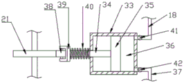
Fig. 3 is an enlarged view of the negative pressure assembly of fig. 1.
Fig. 4 is a front sectional view of the painting mechanism of fig. 1.
Fig. 5 is a three-dimensional view of a rotary block in a painting apparatus for construction.
In the figure: 1-a movable base, 2-an installation box, 3-a lifting frame, 4-a material storage box, 5-a paint pump, 6-a lead screw, 7-a slide rod, 8-a support plate, 9-a support frame, 10-a roller, 11-a through hole, 12-a paint brushing hair sleeve, 13-a first motor, 14-a sliding sleeve, 15-a moving block, 16-a brush, 17-an ash collecting groove, 18-an air suction pipe, 19-a first rotating shaft, 20-a second rotating shaft, 21-a rotating block, 22-a stirring rod, 23-a third motor, 24-a belt pulley component, 25-a spring, 26-a movable wheel, 27-a guide groove, 28-a first gear, 29-a second gear, 30-a steering frame, 31-a second motor, 32-a water tank, 33-a pumping cylinder, 34-a piston rod, 35-a piston block, 36-a negative pressure bin, 37-an exhaust pipe, 38-a roller, 39-a stop block, 40-a return spring, 41-a first one-way valve and 42-a second one-way valve.
Detailed Description
The technical solution of the present patent will be described in further detail with reference to the following embodiments.
Example 1
Referring to fig. 1-5, a painting device for buildings comprises a movable base 1, an installation box 2 and a lifting frame 3, wherein the installation box 2 and the lifting frame 3 are both fixedly arranged on the top surface of the movable base 1, a push-pull rod is fixedly arranged on the side surface of the installation box 2, universal wheels are fixedly arranged on the bottom surface of the movable base 1, a lifting mechanism is arranged in the lifting frame 3, a painting mechanism and a cleaning mechanism are arranged on the lifting mechanism, the cleaning mechanism is positioned above the painting mechanism, a storage box 4 and a painting pump 5 are arranged in the installation box 2, a feeding channel communicated with the storage box 4 is arranged on the top of the installation box 2, a stirring mechanism is arranged in the storage box 4, the input end of the painting pump 5 is communicated with the bottom of the side surface of the storage box 4 through a hose, the output end of the painting pump 5 is communicated with the painting mechanism through a hose, the lifting mechanism comprises a lead screw 6 and a slide, the lead screw 6 is rotatably arranged in the lifting frame 3, the lead screw 6 is driven by a first motor 13 arranged at the top of the lifting frame 3, and the slide rod 7 is fixedly arranged in the lifting frame 3 and positioned in front of the lead screw 6; the painting mechanism comprises a supporting plate 8, the supporting plate 8 is movably mounted on a screw rod 6 and a sliding rod 7, a supporting frame 9 is fixedly arranged at the front end of the supporting plate 8, a roller 10 is rotatably connected onto the supporting frame 9, the roller 10 is of a hollow structure, a plurality of through holes 11 are formed in the roller 10, and a painting brush sleeve 12 is sleeved outside the roller 10; the cleaning mechanism comprises a moving block 15 in threaded fit with the lead screw 6, a sliding sleeve 14, a moving block 15, a brush 16, an ash collecting groove 17 and a negative pressure component, the sliding sleeve 14 is slidably arranged on the sliding rod 7, the bottom surface of the sliding sleeve 14 is fixedly connected with the supporting plate 8, the side surface of the sliding sleeve 14 is fixedly connected with the moving block 15 through a connecting rod, the sliding sleeve 14 is provided with a rotating component for driving the brush 16 to rotate, the ash collecting groove 17 is fixedly arranged on the supporting plate 8 between the brush 16 and the paint brush sleeve 12, the bottom of the ash collecting groove 17 is connected with the negative pressure component through an air suction pipe 18, the rotating component comprises a first gear 28, a second gear 29 and a bogie 30 arranged on the sliding sleeve 14, the first gear 28 is fixedly sleeved on the sliding sleeve 14, the bogie 30 is rotatably connected with the sliding sleeve 14, the bottom of the bogie 30 is fixedly provided with a second motor 31, an output shaft of the second motor 31 is fixedly provided with a second gear 29 engaged with the first gear 28, through setting up elevating system and mopping mechanism, first motor 13 rotates and can drive and clean mechanism and mopping mechanism and reciprocate, thereby roll the mopping to the building of eminence, it is convenient to use, clean mechanism and rotating assembly through the setting, second motor 31 rotates, and cooperate first gear 28 and the meshing transmission of second gear 29, thereby make bogie 30 rotatory, the brush 16 of cooperation bogie 30 front end setting, can clean the processing to the dirt bits on wall surface, thereby the quality of mopping has been improved.
In addition, a filter screen is arranged above the air suction pipe 18 in the dust collection groove 17, and large-particle impurities are filtered by the filter screen, so that the air suction pipe 18 is blocked by large-particle impurities in spinning.
Wherein, the negative pressure component comprises a water tank 32, a pumping cylinder 33, a piston block 35 and a piston rod 34, the water tank 32 is fixedly arranged in the installation box 2, the pumping cylinder 33 is fixedly arranged at the top of the inner cavity of the installation box 2 through a connecting block, the piston block 35 is arranged in the pumping cylinder 33 in a sealing and sliding manner, a negative pressure bin 36 is formed between the right side surface of the piston block 35 and the inner wall of the pumping cylinder 33, the top of the side surface of the negative pressure bin 36 is communicated with an air suction pipe 18, the bottom of the side surface of the negative pressure bin 36 is communicated with the water tank 32 through an air exhaust pipe 37, a first one-way valve 41 which only allows air to flow into the negative pressure bin 36 is arranged at the joint of the air suction pipe 18 and the negative pressure bin 36, a second one-way valve 42 which only allows air to flow into the water tank 32 from the negative pressure bin 36 is arranged at the joint of the air suction pipe 37, and one end of the piston rod 34 penetrating the draw tube 33 is rotatably provided with a roller 38, the roller 38 is contacted with the side surface of the rotating block 21, a stop block 39 is fixedly arranged on the rod body at one side of the piston rod 34 far away from the roller 38, and the rod body of the piston rod 34 between the stop 39 and the draw tube 33 is sleeved with a return spring 40, by arranging the negative pressure component, the rotating block 21 rotates, the piston block 35 reciprocates in the pumping cylinder 33 through the matching of the roller 38, the piston rod 34 and the piston block 35, so as to generate negative pressure in the negative pressure bin 36, and with the cooperation of the suction pipe 18, the exhaust pipe 37, the first one-way valve 41 and the second one-way valve 42, the cleaned large-particle impurities are collected in the dust collecting groove 17, the small-particle dust is sucked into the negative pressure bin 36 through the suction pipe 18 and is discharged into the water tank 32 through the exhaust pipe 37, the dust collector has the functions of dust collection and dust fall on the cleaned dust, and the dust is prevented from causing physical injury to workers.
Example 2
The embodiment performs function expansion on the basis of embodiment 1, specifically:
the stirring mechanism comprises a first rotating shaft 19, a second rotating shaft 20, a rotating block 21 and stirring rods 22, the first rotating shaft 19 is rotatably connected with the installation box 2, the first rotating shaft 19 is driven by a third motor 23 arranged on the top surface of the installation box 2, a plurality of stirring rods 22 are arranged on a rod body of the first rotating shaft 19 in the storage box 4, the second rotating shaft 20 is vertically and rotatably arranged on one side, far away from the first rotating shaft 19, in the installation box 2, the second rotating shaft 20 is in transmission connection with the first rotating shaft 19 through a belt pulley component 24, the rotating block 21 is fixedly arranged on the second rotating shaft 20, the rotating block 21 is in contact with the side surface of the storage box 4, the side surface of the storage box 4 is connected with the inner side wall of the installation box 2 through a spring 25, a moving wheel 26 is fixedly arranged at the bottom of the storage box 4, a guide groove 27 for the moving wheel 26 to walk is formed in the top surface of the moving base 1, and, the third motor 23 drives the first rotating shaft 19 to rotate, so that the stirring rod 22 stirs the paint in the storage box 4, the phenomenon that the paint in the storage box 4 is solidified is avoided, and the painting efficiency is further improved; through setting up turning block 21, spring 25 and removal wheel 26, when first pivot 19 rotated, rotated through 24 band-pass second pivots 20 of pulley subassembly to through the cooperation of turning block 21 with storage case 4, make storage case 4 left and right sides reciprocating motion, thereby make puddler 22 carry out intensive mixing to storage case 4 inside, further improved the stirring effect of puddler 22 to the interior paint of storage case 4.
It will be evident to those skilled in the art that the invention is not limited to the details of the foregoing illustrative embodiments, and that the present invention may be embodied in other specific forms without departing from the spirit or essential attributes thereof. The present embodiments are therefore to be considered in all respects as illustrative and not restrictive, the scope of the invention being indicated by the appended claims rather than by the foregoing description, and all changes which come within the meaning and range of equivalency of the claims are therefore intended to be embraced therein.
Furthermore, it should be understood that although the present description refers to embodiments, not every embodiment may contain only a single embodiment, and such description is for clarity only, and those skilled in the art should integrate the description, and the embodiments may be combined as appropriate to form other embodiments understood by those skilled in the art.
Claims (7)
1. A painting device for buildings comprises a movable base (1), an installation box (2) and a lifting frame (3), and is characterized in that the installation box (2) and the lifting frame (3) are fixedly arranged on the top surface of the movable base (1), a push-pull rod is fixedly arranged on the side surface of the installation box (2), universal wheels are fixedly arranged on the bottom surface of the movable base (1), a lifting mechanism is arranged in the lifting frame (3), a painting mechanism and a cleaning mechanism are arranged on the lifting mechanism and positioned above the painting mechanism, a storage box (4) and a painting pump (5) are arranged in the installation box (2), a feeding channel communicated with the storage box (4) is arranged at the top of the installation box (2), a stirring mechanism is arranged in the storage box (4), and the input end of the painting pump (5) is communicated with the bottom of the storage box (4) through a hose, the output end of the paint pump (5) is communicated with the painting mechanism through a hose,
the lifting mechanism comprises a lead screw (6) and a slide rod (7), the lead screw (6) is rotatably arranged in the lifting frame (3), the lead screw (6) is driven by a first motor (13) arranged at the top of the lifting frame (3), and the slide rod (7) is fixedly arranged in the lifting frame (3) and positioned in front of the lead screw (6);
the painting mechanism comprises a supporting plate (8), the supporting plate (8) is movably mounted on a lead screw (6) and a sliding rod (7), a supporting frame (9) is fixedly arranged at the front end of the supporting plate (8), a roller (10) is rotatably connected onto the supporting frame (9), the roller (10) is of a hollow structure, a plurality of through holes (11) are formed in the roller (10), and a painting hairsleeve (12) is sleeved outside the roller (10);
the cleaning mechanism comprises a moving block (15) in threaded fit with a lead screw (6), a sliding sleeve (14), a brush (16), an ash collecting groove (17) and a negative pressure component, the sliding sleeve (14) is arranged on a sliding rod (7) in a sliding mode, the bottom surface of the sliding sleeve (14) is fixedly connected with a supporting plate (8), the side surface of the sliding sleeve (14) is fixedly connected with the moving block (15) through a connecting rod, a rotating component used for driving the brush (16) to rotate is arranged on the sliding sleeve (14), the ash collecting groove (17) is fixedly arranged on the supporting plate (8) between the brush (16) and a paint brushing hairsleeve (12), and the bottom of the ash collecting groove (17) is connected with the negative pressure component through an air suction pipe (18).
2. A painting apparatus for buildings according to claim 1, characterized in that a screen is provided in the dust collection tank (17) above the suction pipe (18).
3. A painting device for buildings according to claim 1, characterized in that said stirring means comprise a first rotating shaft (19), a second rotating shaft (20), a rotating block (21) and a stirring rod (22), said first rotating shaft (19) being rotatably connected with the mounting box (2), and the first rotating shaft (19) is driven by a third motor (23) arranged on the top surface of the mounting box (2), a plurality of stirring rods (22) are arranged on the rod body of the first rotating shaft (19) positioned in the material storage box (4), the second rotating shaft (20) is vertically and rotatably arranged on one side, far away from the first rotating shaft (19), in the installation box (2), and the second rotating shaft (20) is in transmission connection with the first rotating shaft (19) through a belt pulley component (24), the rotating block (21) is fixedly arranged on the second rotating shaft (20), and the rotating block (21) is in contact with the side surface of the material storage box (4).
4. The painting device for buildings according to claim 3, wherein the side surface of the storage box (4) is connected with the inner side wall of the installation box (2) through a spring (25), the bottom of the storage box (4) is fixedly provided with rollers (38) (26), and the top surface of the movable base (1) is provided with a guide groove (27) for the movable roller (26) to travel.
5. The architectural painting device according to claim 1, wherein the rotating assembly comprises a first gear (28), a second gear (29) and a bogie (30) mounted on the sliding sleeve (14), the first gear (28) is fixedly sleeved on the sliding sleeve (14), the bogie (30) is rotatably connected with the sliding sleeve (14), a second motor (31) is fixedly arranged at the bottom of the bogie (30), and a second gear (29) meshed with the first gear (28) is fixedly arranged on an output shaft of the second motor (31).
6. The architectural painting device according to claim 1, wherein the negative pressure assembly comprises a water tank (32), a pumping cylinder (33), a piston block (35) and a piston rod (34), the water tank (32) is fixedly arranged in the installation box (2), the pumping cylinder (33) is fixedly arranged at the top of the inner cavity of the installation box (2) through a connecting block, the piston block (35) is hermetically and slidably arranged in the pumping cylinder (33), a negative pressure bin (36) is formed between the right side surface of the piston block (35) and the inner wall of the pumping cylinder (33), the top of the side surface of the negative pressure bin (36) is communicated with the air suction pipe (18), the bottom of the side surface of the negative pressure bin (36) is communicated with the water tank (32) through an exhaust pipe (37), one end of the piston rod (34) is fixedly connected with the piston block (35), and the other end of the piston rod (34) is slidably connected with the side surface of the pumping cylinder (33), and piston rod (34) wear to establish and rotate to the outer one end of taking out a section of thick bamboo (33) and be equipped with gyro wheel (38), gyro wheel (38) contact with turning block (21) side, fixed being equipped with dog (39) on the body of rod of piston rod (34) keep away from gyro wheel (38) one side, and piston rod (34) are located dog (39) and take out the body of rod between a section of thick bamboo (33) and overlap and be equipped with reset spring (40).
7. A painting device for buildings according to claim 6, characterized in that the connection between the suction pipe (18) and the negative pressure chamber (36) is provided with a first one-way valve (41) which only allows air to flow into the negative pressure chamber (36), and the connection between the exhaust pipe (37) and the negative pressure chamber (36) is provided with a second one-way valve (42) which only allows air to flow from the negative pressure chamber (36) to the water tank (32).
Priority Applications (1)
| Application Number | Priority Date | Filing Date | Title |
|---|---|---|---|
| CN202011215317.9A CN112360112A (en) | 2020-11-04 | 2020-11-04 | Painting device for building |
Applications Claiming Priority (1)
| Application Number | Priority Date | Filing Date | Title |
|---|---|---|---|
| CN202011215317.9A CN112360112A (en) | 2020-11-04 | 2020-11-04 | Painting device for building |
Publications (1)
| Publication Number | Publication Date |
|---|---|
| CN112360112A true CN112360112A (en) | 2021-02-12 |
Family
ID=74513570
Family Applications (1)
| Application Number | Title | Priority Date | Filing Date |
|---|---|---|---|
| CN202011215317.9A Withdrawn CN112360112A (en) | 2020-11-04 | 2020-11-04 | Painting device for building |
Country Status (1)
| Country | Link |
|---|---|
| CN (1) | CN112360112A (en) |
Cited By (6)
| Publication number | Priority date | Publication date | Assignee | Title |
|---|---|---|---|---|
| CN113202269A (en) * | 2021-05-06 | 2021-08-03 | 湖北嘉筑建设工程有限公司 | Green coating construction device for building wall surface and construction process thereof |
| CN113208491A (en) * | 2021-07-07 | 2021-08-06 | 南通弈驰新型建材科技有限公司 | Intelligence sliding door for house |
| CN113441328A (en) * | 2021-07-08 | 2021-09-28 | 黄亭亭 | Product spraying equipment for intelligent manufacturing production |
| CN114086743A (en) * | 2021-12-07 | 2022-02-25 | 宿松恒骏装饰新材料科技有限公司 | Novel material spraying equipment is decorated to building side fascia |
| CN114232952A (en) * | 2022-01-04 | 2022-03-25 | 叶成 | A cementation of fissures filling device for vertical veneer face |
| CN114396152A (en) * | 2022-01-19 | 2022-04-26 | 安徽檀松建筑工程有限公司 | Building external wall panel waterproof coating spraying equipment |
-
2020
- 2020-11-04 CN CN202011215317.9A patent/CN112360112A/en not_active Withdrawn
Cited By (8)
| Publication number | Priority date | Publication date | Assignee | Title |
|---|---|---|---|---|
| CN113202269A (en) * | 2021-05-06 | 2021-08-03 | 湖北嘉筑建设工程有限公司 | Green coating construction device for building wall surface and construction process thereof |
| CN113202269B (en) * | 2021-05-06 | 2023-01-20 | 湖北嘉筑建设工程有限公司 | Green coating construction device for building wall surface and construction process thereof |
| CN113208491A (en) * | 2021-07-07 | 2021-08-06 | 南通弈驰新型建材科技有限公司 | Intelligence sliding door for house |
| CN113441328A (en) * | 2021-07-08 | 2021-09-28 | 黄亭亭 | Product spraying equipment for intelligent manufacturing production |
| CN113441328B (en) * | 2021-07-08 | 2022-05-17 | 黄亭亭 | Product spraying equipment for intelligent manufacturing production |
| CN114086743A (en) * | 2021-12-07 | 2022-02-25 | 宿松恒骏装饰新材料科技有限公司 | Novel material spraying equipment is decorated to building side fascia |
| CN114232952A (en) * | 2022-01-04 | 2022-03-25 | 叶成 | A cementation of fissures filling device for vertical veneer face |
| CN114396152A (en) * | 2022-01-19 | 2022-04-26 | 安徽檀松建筑工程有限公司 | Building external wall panel waterproof coating spraying equipment |
Similar Documents
| Publication | Publication Date | Title |
|---|---|---|
| CN112360112A (en) | Painting device for building | |
| CN112030432A (en) | Textile material washing equipment with high washing efficiency | |
| CN208193954U (en) | A kind of multielement synchronous slow fertilizer specially for wheat process units | |
| CN114210147A (en) | High-efficient dust fall equipment of building site | |
| CN213409384U (en) | Rice sieving mechanism with dust removal function | |
| CN216830016U (en) | Grinding device is used in architectural decoration construction | |
| CN217367595U (en) | Toilet uses fan filter equipment | |
| CN214914617U (en) | Civil engineering construction dust collection device | |
| CN214635067U (en) | Building engineering construction dust collector | |
| CN214130466U (en) | Building drainage filter equipment that can handle impurity | |
| CN113798270A (en) | Environment-friendly transmission shaft processing dust collector | |
| CN108654237A (en) | A kind of quick dust-collecting type environmental protection air filter | |
| CN213896941U (en) | Green dust collector for building engineering | |
| CN208583098U (en) | A kind of quick dust-collecting type environmental protection air filter | |
| CN215352740U (en) | Energy-saving dust collecting equipment for construction | |
| CN113996521A (en) | Cleaning device for axial coal accumulated on roller screen | |
| CN111395234A (en) | Road auxiliary cleaning device | |
| CN214883318U (en) | Building site environment improvement device for engineering management | |
| CN211070988U (en) | Modified asphalt waterproof coating basic unit processing apparatus | |
| CN214484421U (en) | Ground cleaning equipment with adjusting function for panel processing | |
| CN216578503U (en) | A dust keeper for concrete mixer | |
| CN218980878U (en) | Dust collecting device of industrial dust remover | |
| CN220521189U (en) | Municipal road cleaning device | |
| CN220813626U (en) | Multifunctional road sweeper | |
| CN220842456U (en) | Robot inspection equipment |
Legal Events
| Date | Code | Title | Description |
|---|---|---|---|
| PB01 | Publication | ||
| PB01 | Publication | ||
| SE01 | Entry into force of request for substantive examination | ||
| SE01 | Entry into force of request for substantive examination | ||
| WW01 | Invention patent application withdrawn after publication |
Application publication date: 20210212 |
|
| WW01 | Invention patent application withdrawn after publication |