CN112356380A - Automatic injection molding machine is used in auto plastic accessory processing - Google Patents
Automatic injection molding machine is used in auto plastic accessory processing Download PDFInfo
- Publication number
- CN112356380A CN112356380A CN202011012065.XA CN202011012065A CN112356380A CN 112356380 A CN112356380 A CN 112356380A CN 202011012065 A CN202011012065 A CN 202011012065A CN 112356380 A CN112356380 A CN 112356380A
- Authority
- CN
- China
- Prior art keywords
- injection molding
- molding machine
- fixedly arranged
- motor
- machine body
- Prior art date
- Legal status (The legal status is an assumption and is not a legal conclusion. Google has not performed a legal analysis and makes no representation as to the accuracy of the status listed.)
- Pending
Links
Images


Classifications
-
- B—PERFORMING OPERATIONS; TRANSPORTING
- B29—WORKING OF PLASTICS; WORKING OF SUBSTANCES IN A PLASTIC STATE IN GENERAL
- B29C—SHAPING OR JOINING OF PLASTICS; SHAPING OF MATERIAL IN A PLASTIC STATE, NOT OTHERWISE PROVIDED FOR; AFTER-TREATMENT OF THE SHAPED PRODUCTS, e.g. REPAIRING
- B29C45/00—Injection moulding, i.e. forcing the required volume of moulding material through a nozzle into a closed mould; Apparatus therefor
- B29C45/03—Injection moulding apparatus
-
- B—PERFORMING OPERATIONS; TRANSPORTING
- B03—SEPARATION OF SOLID MATERIALS USING LIQUIDS OR USING PNEUMATIC TABLES OR JIGS; MAGNETIC OR ELECTROSTATIC SEPARATION OF SOLID MATERIALS FROM SOLID MATERIALS OR FLUIDS; SEPARATION BY HIGH-VOLTAGE ELECTRIC FIELDS
- B03C—MAGNETIC OR ELECTROSTATIC SEPARATION OF SOLID MATERIALS FROM SOLID MATERIALS OR FLUIDS; SEPARATION BY HIGH-VOLTAGE ELECTRIC FIELDS
- B03C1/00—Magnetic separation
- B03C1/02—Magnetic separation acting directly on the substance being separated
- B03C1/16—Magnetic separation acting directly on the substance being separated with material carriers in the form of belts
- B03C1/18—Magnetic separation acting directly on the substance being separated with material carriers in the form of belts with magnets moving during operation
-
- B—PERFORMING OPERATIONS; TRANSPORTING
- B29—WORKING OF PLASTICS; WORKING OF SUBSTANCES IN A PLASTIC STATE IN GENERAL
- B29B—PREPARATION OR PRETREATMENT OF THE MATERIAL TO BE SHAPED; MAKING GRANULES OR PREFORMS; RECOVERY OF PLASTICS OR OTHER CONSTITUENTS OF WASTE MATERIAL CONTAINING PLASTICS
- B29B13/00—Conditioning or physical treatment of the material to be shaped
- B29B13/10—Conditioning or physical treatment of the material to be shaped by grinding, e.g. by triturating; by sieving; by filtering
-
- B—PERFORMING OPERATIONS; TRANSPORTING
- B29—WORKING OF PLASTICS; WORKING OF SUBSTANCES IN A PLASTIC STATE IN GENERAL
- B29C—SHAPING OR JOINING OF PLASTICS; SHAPING OF MATERIAL IN A PLASTIC STATE, NOT OTHERWISE PROVIDED FOR; AFTER-TREATMENT OF THE SHAPED PRODUCTS, e.g. REPAIRING
- B29C45/00—Injection moulding, i.e. forcing the required volume of moulding material through a nozzle into a closed mould; Apparatus therefor
- B29C45/17—Component parts, details or accessories; Auxiliary operations
- B29C45/1761—Means for guiding movable mould supports or injection units on the machine base or frame; Machine bases or frames
-
- B—PERFORMING OPERATIONS; TRANSPORTING
- B29—WORKING OF PLASTICS; WORKING OF SUBSTANCES IN A PLASTIC STATE IN GENERAL
- B29C—SHAPING OR JOINING OF PLASTICS; SHAPING OF MATERIAL IN A PLASTIC STATE, NOT OTHERWISE PROVIDED FOR; AFTER-TREATMENT OF THE SHAPED PRODUCTS, e.g. REPAIRING
- B29C45/00—Injection moulding, i.e. forcing the required volume of moulding material through a nozzle into a closed mould; Apparatus therefor
- B29C45/17—Component parts, details or accessories; Auxiliary operations
- B29C45/18—Feeding the material into the injection moulding apparatus, i.e. feeding the non-plastified material into the injection unit
-
- B—PERFORMING OPERATIONS; TRANSPORTING
- B29—WORKING OF PLASTICS; WORKING OF SUBSTANCES IN A PLASTIC STATE IN GENERAL
- B29C—SHAPING OR JOINING OF PLASTICS; SHAPING OF MATERIAL IN A PLASTIC STATE, NOT OTHERWISE PROVIDED FOR; AFTER-TREATMENT OF THE SHAPED PRODUCTS, e.g. REPAIRING
- B29C45/00—Injection moulding, i.e. forcing the required volume of moulding material through a nozzle into a closed mould; Apparatus therefor
- B29C45/17—Component parts, details or accessories; Auxiliary operations
- B29C45/1761—Means for guiding movable mould supports or injection units on the machine base or frame; Machine bases or frames
- B29C2045/1765—Machine bases
Landscapes
- Engineering & Computer Science (AREA)
- Mechanical Engineering (AREA)
- Manufacturing & Machinery (AREA)
- Injection Moulding Of Plastics Or The Like (AREA)
Abstract
The invention discloses an automatic injection molding machine for processing automobile plastic accessories, which comprises a base, wherein an injection molding machine body is fixedly arranged on one side of the upper end of the base, a function bin is fixedly arranged on one side of the upper end of the base, which is far away from the injection molding machine body, a transmission rod is movably arranged in the middle of the inner side of the injection molding machine body through a rotating shaft, a first motor is fixedly arranged on one side, which is close to the transmission rod, in the function bin through a mounting seat, the output shaft end of the first motor is in transmission connection with the transmission rod through a coupler, and a screening mechanism is arranged on the upper end of the function bin and comprises a first support, a first conveying belt, a second support, a fixing frame, a second conveying belt, a second motor. The invention has good use effect, and can effectively prevent small-particle iron blocks or iron balls which are not easy to melt from being mixed in plastic particles and entering the injection molding machine body through the screening mechanism, thereby effectively preventing the injection molding machine body from being blocked.
Description
Technical Field
The invention relates to the technical field of automatic injection molding machines, in particular to an automatic injection molding machine for processing automobile plastic accessories.
Background
An injection molding machine is also known as an injection molding machine or an injection machine. It is a main forming equipment for making various shaped plastic products from thermoplastic plastics or thermosetting plastics by using plastic forming mould. The device is divided into a vertical type, a horizontal type and a full-electric type. The injection molding machine can heat the plastic, apply high pressure to the molten plastic, and inject it to fill the mold cavity.
However, when plastic particles are injected into the injection molding machine used at present, a screening mechanism is lacked, so that small iron blocks or steel balls are easy to penetrate through the filter screen to reach the interior of the injection molding machine body, and therefore injection molding holes of the injection molding machine cannot be melted and blocked, and unnecessary economic loss is generated.
Disclosure of Invention
The invention aims to provide an automatic injection molding machine for processing automobile plastic parts, which aims to solve the problems in the background technology.
In order to achieve the purpose, the invention provides the following technical scheme: an automatic injection molding machine for processing automobile plastic parts comprises a base, wherein an injection molding machine body is fixedly arranged on one side of the upper end of the base, a function bin is fixedly arranged on one side, far away from the injection molding machine body, of the upper end of the base, a transmission rod is movably arranged in the middle of the inner side of the injection molding machine body through a rotating shaft, a first motor is fixedly arranged on one side, close to the transmission rod, in the function bin through a mounting seat, the output shaft end of the first motor is in transmission connection with the transmission rod through a coupler, a screening mechanism is arranged on the upper end of the function bin and comprises a first support, a first conveying belt, a second support, a fixing frame, a second conveying belt, a second motor, a third motor and a strong magnet, the first support is fixedly arranged on two sides of the upper end of the function bin, and the first, the fixed second support that is provided with in function storehouse upper end middle part, the fixed mount that is provided with in second support upper end, the mount lower extreme is provided with the second conveyer belt through the pivot activity, the inside one side of keeping away from first motor in function storehouse is provided with the second motor through the mount pad is fixed, the output axle head of second motor passes through the belt, the belt pulley is connected with the transmission between the first conveyer belt, the mount upper end is provided with the third motor through the mount pad is fixed, the output axle head of third motor passes through the belt, the belt pulley is connected with the transmission between the second conveyer belt, the second conveyer belt outside surface is even fixed and is provided with a plurality of strong magnets, the fixed feed mechanism that is provided with in injection molding machine body upper end.
Preferably, feed mechanism includes feed inlet, inlet pipe, fourth motor, puddler, the fixed feed inlet that is provided with in injection molding machine body upper end, the fixed inlet pipe that is provided with in one side on the feed inlet, feed inlet upper end middle part is provided with the fourth motor through the mount pad is fixed, the feed inlet inboard is provided with the puddler through the bearing activity, the output shaft end of fourth motor passes through the shaft coupling and is connected with the transmission between the puddler, can conveniently pour into plastic granules into to injection molding machine body inside through feed mechanism, can play simultaneously and prevent stifled effect.
Preferably, a funnel is fixedly arranged at one end of the feeding pipe close to the first conveyor belt, and plastic particles conveyed by the first conveyor belt can be conveniently collected through the funnel.
Preferably, a bottom plate is fixedly arranged at the lower end of the base, a moving mechanism is arranged in the bottom plate and comprises a telescopic rod, a moving plate, a first extrusion block, a mounting plate, an electric push rod, a second extrusion block and universal wheels, the telescopic rods are fixedly arranged at the four corners of the upper end of the inner side of the bottom plate, the moving plate is fixedly arranged at the lower end of the telescopic rod, the first extrusion block is fixedly arranged in the middle of the upper end of the moving plate, the mounting plate is fixedly arranged at the two sides of the upper end of the inner part of the bottom plate, the electric push rod is fixedly arranged at one side of the mounting plate close to the first extrusion block through a mounting seat, the second extrusion block is fixedly arranged at the shaft end of the telescopic rod of the electric push rod, the outer side surfaces of the first extrusion block and the second extrusion block are mutually attached, the universal wheels are, when not needed, the utility model is stored.
Preferably, the telescopic link is internally provided with a spring, and the stability of the telescopic link during contraction can be improved through the spring.
Preferably, the fixed extension rod that is provided with in mount one side, the fixed scraper blade that is provided with in extension rod surface middle part, the fixed receiver that is provided with of extension rod lower extreme can conveniently accomodate the iron plate that adsorbs on the strong magnet through scraper blade and receiver.
Preferably, the sliding groove is formed in the upper end of the inner portion of the bottom plate, the upper end of the second extrusion block is movably clamped inside the sliding groove, and stability of the second extrusion block in the process of moving left and right can be improved through the sliding groove.
Preferably, the upper end of the fixing frame is fixedly provided with a protective cover outside the third motor, and the protective cover can play a role in protecting the third motor.
Preferably, the heating pipe is fixedly arranged on the inner side wall of the injection molding machine body, and the temperature in the injection molding machine body can be maintained through the heating pipe.
Compared with the prior art, the invention has the beneficial effects that:
1. according to the invention, the second conveyor belt can be opened when the first conveyor belt works, then the second conveyor belt drives the strong magnet to rotate, the small granular iron blocks or iron balls which are not easy to melt in the plastic granules on the surface of the first conveyor belt are adsorbed by the strong magnet, so that the small granular iron blocks or iron balls which are not easy to melt can be effectively prevented from entering the injection molding machine body to cause blockage of the injection molding machine body, and then the small granular iron blocks adsorbed on the surface of the strong magnet can be contacted with the scraper along with the movement of the second conveyor belt, so that the iron blocks can be scraped off by the scraper and fall into the storage box for storage.
2. When plastic particles enter the feeding hole, the plastic particles in the feeding hole are possibly slightly melted and adhered together due to heat in the injection molding machine body, and at the moment, the stirring rod can be driven to rotate through the fourth motor, so that the adhered plastic particles can be scattered, and the feeding hole can be effectively prevented from being blocked.
3. When the device needs to be transported and displaced, the second extrusion block can be pushed to extrude the first extrusion block through electric pushing, so that the first extrusion block and the moving plate move downwards, the device can be supported through the universal wheels, and the displacement can be conveniently carried out.
Drawings
FIG. 1 is a schematic view of the overall structure of an automatic injection molding machine for processing automobile plastic parts according to the present invention;
FIG. 2 is a schematic diagram of the overall structure of a feeding mechanism of an automatic injection molding machine for processing automobile plastic parts according to the present invention;
FIG. 3 is an installation view of a heating pipe of an automatic injection molding machine for processing automobile plastic parts according to the present invention.
FIG. 4 is a schematic diagram of the overall structure of the moving mechanism of the automatic injection molding machine for processing automobile plastic parts according to the present invention.
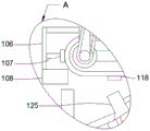
FIG. 5 is an enlarged view of the portion A of FIG. 1 of the automatic injection molding machine for processing automobile plastic parts according to the present invention.
In the figure: 100. a base; 101. an injection molding machine body; 102. a functional bin; 103. a transmission rod; 104. a first motor; 105. a base plate; 106. an extension rod; 107. a squeegee; 108. a storage box; 109. heating a tube; 110. a screening mechanism; 111. a first bracket; 112. a first conveyor belt; 113. a second bracket; 114. a fixed mount; 115. a second conveyor belt; 116. a second motor; 117. a third motor; 118. strong magnets; 119. a protective cover; 120. a feeding mechanism; 121. a feed inlet; 122. a feed pipe; 123. a fourth motor; 124. a stirring rod; 125. a funnel; 130. a moving mechanism; 131. a telescopic rod; 132. moving the plate; 133. a first extrusion block; 134. mounting a plate; 135. an electric push rod; 136. a second extrusion block; 137. a universal wheel; 138. a spring; 139. a chute.
Detailed Description
The technical solutions in the embodiments of the present invention will be clearly and completely described below with reference to the drawings in the embodiments of the present invention, and it is obvious that the described embodiments are only a part of the embodiments of the present invention, and not all of the embodiments. All other embodiments, which can be derived by a person skilled in the art from the embodiments given herein without making any creative effort, shall fall within the protection scope of the present invention.
Referring to fig. 1-5, the present invention provides a technical solution: an automatic injection molding machine for processing automobile plastic accessories comprises a base 100, an injection molding machine body 101 is fixedly arranged on one side of the upper end of the base 100, a function bin 102 is fixedly arranged on one side, far away from the injection molding machine body 101, of the upper end of the base 100, a transmission rod 103 is movably arranged in the middle of the inner side of the injection molding machine body 101 through a rotating shaft, a first motor 104 is fixedly arranged on one side, close to the transmission rod 103, of the inner portion of the function bin 102 through a mounting seat, the output shaft end of the first motor 104 is in transmission connection with the transmission rod 103 through a coupler, a screening mechanism 110 is arranged on the upper end of the function bin 102, the screening mechanism 110 comprises a first support 111, a first transmission belt 112, a second support 113, a fixed support 114, a second transmission belt 115, a second motor 116, a third motor 117 and a strong magnet 118, the first supports 111, a first conveyor belt 112 is movably arranged at the upper end of the first bracket 111 through a rotating shaft, a second bracket 113 is fixedly arranged at the middle part of the upper end of the functional cabin 102, the upper end of the second bracket 113 is fixedly provided with a fixed frame 114, the lower end of the fixed frame 114 is movably provided with a second conveyor belt 115 through a rotating shaft, a second motor 116 is fixedly arranged on one side of the interior of the functional cabin 102 far away from the first motor 104 through a mounting seat, the output shaft end of the second motor 116 is in transmission connection with the first conveyor belt 112 through a belt and a pulley, the upper end of the fixed frame 114 is fixedly provided with a third motor 117 through a mounting seat, the output shaft end of the third motor 117 is in transmission connection with a second conveyor belt 115 through a belt and a belt pulley, a plurality of strong magnets 118 are uniformly and fixedly arranged on the outer side surface of the second conveyor belt 115, and a feeding mechanism 120 is fixedly arranged at the upper end of the injection molding machine body 101.
The feeding mechanism 120 comprises a feeding port 121, a feeding pipe 122, a fourth motor 123 and a stirring rod 124, the feeding port 121 is fixedly arranged at the upper end of the injection molding machine body 101, the feeding pipe 122 is fixedly arranged at one side of the feeding port 121, the fourth motor 123 is fixedly arranged at the middle part of the upper end of the feeding port 121 through a mounting seat, the stirring rod 124 is movably arranged at the inner side of the feeding port 121 through a bearing, an output shaft end of the fourth motor 123 is in transmission connection with the stirring rod 124 through a coupler, plastic particles can be conveniently injected into the injection molding machine body 101 through the feeding mechanism 120, meanwhile, an anti-blocking effect can be achieved, a funnel 125 is fixedly arranged at one end of the feeding pipe 122 close to the first conveying belt 112, the plastic particles conveyed down by the first conveying belt 112 can be conveniently collected through the funnel, the inner part of the bottom plate 105 is provided with a moving mechanism 130, the moving mechanism 130 comprises a telescopic rod 131, a moving plate 132, a first extrusion block 133, an installation plate 134, an electric push rod 135, a second extrusion block 136 and universal wheels 137, the four corners of the inner upper end of the bottom plate 105 are all fixedly provided with the telescopic rod 131, the lower end of the telescopic rod 131 is fixedly provided with the moving plate 132, the middle part of the upper end of the moving plate 132 is fixedly provided with the first extrusion block 133, the two sides of the inner upper end of the bottom plate 105 are both fixedly provided with the installation plate 134, one side of the installation plate 134 close to the first extrusion block 133 is fixedly provided with the electric push rod 135 through an installation seat, the shaft end of the telescopic rod 131 of the electric push rod 135 is fixedly provided with the second extrusion block 136, the outer side surfaces of the first extrusion block 133 and the second extrusion block 136 are mutually, the device can be conveniently moved when needed through the moving mechanism 130 and can be stored when not needed, the spring 138 is arranged in the telescopic rod 131, the stability of the telescopic rod 131 when the telescopic rod 131 is contracted can be improved through the spring 138, the extension rod 106 is fixedly arranged on one side of the fixing frame 114, the scraper 107 is fixedly arranged in the middle of the surface of the extension rod 106, the storage box 108 is fixedly arranged at the lower end of the extension rod 106, an iron block adsorbed on the strong magnet 118 can be conveniently stored through the scraper 107 and the storage box 108, the sliding groove 139 is formed in the upper end of the inner part of the bottom plate 105, the upper end of the second extrusion block 136 is movably clamped and arranged in the sliding groove 139, the stability of the second extrusion block 136 when moving left and right can be improved through the sliding groove 139, the protective cover 119 is fixedly arranged at the outer side of the third motor 117 at the upper, the heating pipe 109 is fixedly arranged on the inner side wall of the injection molding machine body 101, and the temperature inside the injection molding machine body 101 can be maintained through the heating pipe 109.
The working principle is as follows: when the device is used, plastic particles can be conveyed to the interior of the hopper 125 through the first conveyor belt 112, the second conveyor belt 115 can be opened when the first conveyor belt 112 works, then the second conveyor belt 115 drives the strong magnet 118 to rotate, small iron particles or iron balls which are not easy to melt in the plastic particles on the surface of the first conveyor belt 112 are adsorbed by the strong magnet 118, so that the small iron particles or the iron balls which are not easy to melt can be effectively prevented from entering the interior of the injection molding machine body 101, the injection molding machine body 101 is blocked, and then the small iron particles adsorbed on the surface of the strong magnet 118 can be contacted with the scraper 107 along with the movement of the second conveyor belt 115, so that the iron particles can be scraped off by the scraper 107 and fall in the storage box 108 for storage, then screened plastic particles can enter the feed pipe 122 through the hopper 125 and then enter the feed port 121 through the feed pipe 122, when plastic particles enter the feeding hole 121, the plastic particles inside the feeding hole 121 may be slightly melted and adhered together due to the heat inside the injection molding machine body 101, at this time, the stirring rod 124 may be driven to rotate by the fourth motor 123, so that the adhered plastic particles may be scattered, thereby effectively preventing the feeding hole 121 from being blocked, finally, the plastic particles may enter the injection molding machine body 101 to be melted and injected, when the device needs to be carried and displaced, the second extrusion block 136 may be pushed by electric push to extrude the first extrusion block 133, thereby the first extrusion block 133 and the moving plate 132 move downwards, so that the device may be supported by the universal wheel 137, thereby being convenient to be displaced, when the device needs to work, the electric push rod 135 is controlled to be contracted, so that the second extrusion block 136 does not extrude the first extrusion block 133 any more, therefore, the movable plate 132 can move upwards, so that the universal wheels 137 are contracted in the bottom plate 105, the bottom plate 105 is grounded, and the stability of the device in use can be improved, which is the working principle of the automatic injection molding machine for processing the automobile plastic parts.
It is noted that, herein, relational terms such as first and second, and the like may be used solely to distinguish one entity or action from another entity or action without necessarily requiring or implying any actual such relationship or order between such entities or actions. Also, the terms "comprises," "comprising," or any other variation thereof, are intended to cover a non-exclusive inclusion, such that a process, method, article, or apparatus that comprises a list of elements does not include only those elements but may include other elements not expressly listed or inherent to such process, method, article, or apparatus.
Although embodiments of the present invention have been shown and described, it will be appreciated by those skilled in the art that changes, modifications, substitutions and alterations can be made in these embodiments without departing from the principles and spirit of the invention, the scope of which is defined in the appended claims and their equivalents.
Claims (9)
1. The utility model provides an automatic injection molding machine is used in processing of auto plastic spare part, includes base (100), its characterized in that: an injection molding machine body (101) is fixedly arranged on one side of the upper end of the base (100), a function bin (102) is fixedly arranged on one side, far away from the injection molding machine body (101), of the upper end of the base (100), a transmission rod (103) is movably arranged in the middle of the inner side of the injection molding machine body (101) through a rotating shaft, a first motor (104) is fixedly arranged on one side, close to the transmission rod (103), of the inside of the function bin (102) through a mounting seat, the output shaft end of the first motor (104) is in transmission connection with the transmission rod (103) through a coupler, a screening mechanism (110) is arranged on the upper end of the function bin (102), and the screening mechanism (110) comprises a first support (111), a first conveying belt (112), a second support (113), a fixing support (114), a second conveying belt (115), a second motor (116), a third, function storehouse (102) upper end both sides all are fixed and are provided with first support (111), first support (111) upper end is provided with first conveyer belt (112) through the pivot activity, function storehouse (102) upper end middle part is fixed and is provided with second support (113), second support (113) upper end is fixed and is provided with mount (114), mount (114) lower extreme is provided with second conveyer belt (115) through the pivot activity, the inside one side of keeping away from first motor (104) of function storehouse (102) is provided with second motor (116) through the mount pad is fixed, the output axle head of second motor (116) is connected through the transmission between belt, belt pulley and first conveyer belt (112), mount (114) upper end is provided with third motor (117) through the mount pad is fixed, the output axle head of third motor (117) passes through belt, belt, The belt pulley is in transmission connection with a second conveying belt (115), a plurality of strong magnets (118) are uniformly and fixedly arranged on the outer side surface of the second conveying belt (115), and a feeding mechanism (120) is fixedly arranged at the upper end of the injection molding machine body (101).
2. The automatic injection molding machine for processing automobile plastic parts according to claim 1, wherein: feed mechanism (120) include feed inlet (121), inlet pipe (122), fourth motor (123), puddler (124), fixed feed inlet (121) that is provided with in injection molding machine body (101) upper end, the fixed inlet pipe (122) that is provided with in one side on feed inlet (121), feed inlet (121) upper end middle part is through the fixed fourth motor (123) that is provided with of mount pad, feed inlet (121) inboard is provided with puddler (124) through the bearing activity, the output shaft end of fourth motor (123) passes through the shaft coupling and is connected with the transmission between puddler (124).
3. The automatic injection molding machine for processing automobile plastic parts according to claim 2, wherein: and a funnel (125) is fixedly arranged at one end of the feeding pipe (122) close to the first conveyor belt (112).
4. The automatic injection molding machine for processing automobile plastic parts according to claim 1, wherein: the lower end of the base (100) is fixedly provided with a bottom plate (105), a moving mechanism (130) is arranged in the bottom plate (105), the moving mechanism (130) comprises a telescopic rod (131), a moving plate (132), a first extrusion block (133), a mounting plate (134), an electric push rod (135), a second extrusion block (136) and a universal wheel (137), the telescopic rods (131) are fixedly arranged at four corners of the inner upper end of the bottom plate (105), the moving plate (132) is fixedly arranged at the lower end of the telescopic rod (131), the first extrusion block (133) is fixedly arranged in the middle of the upper end of the moving plate (132), the mounting plate (134) is fixedly arranged at two sides of the inner upper end of the bottom plate (105), the electric push rod (135) is fixedly arranged at one side of the mounting plate (134) close to the first extrusion block (133) through a mounting seat, the shaft end (131) of the electric push rod (, the outer side surfaces of the first extrusion block (133) and the second extrusion block (136) are attached to each other, and universal wheels (137) are movably arranged at four corners of the outer side surface of the lower end of the moving plate (132).
5. The automatic injection molding machine for processing automobile plastic parts according to claim 4, wherein: a spring (138) is arranged inside the telescopic rod (131).
6. The automatic injection molding machine for processing automobile plastic parts according to claim 1, wherein: the fixed extension rod (106) that is provided with in mount (114) one side, extension rod (106) fixed scraper blade (107) that is provided with in the middle part of the surface, extension rod (106) lower extreme is fixed and is provided with receiver (108).
7. The automatic injection molding machine for processing automobile plastic parts according to claim 4, wherein: the upper end in the bottom plate (105) is provided with a sliding groove (139), and the upper end of the second extrusion block (136) is movably clamped in the sliding groove (139).
8. The automatic injection molding machine for processing automobile plastic parts according to claim 1, wherein: and a protective cover (119) is fixedly arranged at the upper end of the fixed frame (114) outside the third motor (117).
9. The automatic injection molding machine for processing automobile plastic parts according to claim 1, wherein: and a heating pipe (109) is fixedly arranged on the inner side wall of the injection molding machine body (101).
Priority Applications (1)
| Application Number | Priority Date | Filing Date | Title |
|---|---|---|---|
| CN202011012065.XA CN112356380A (en) | 2020-09-23 | 2020-09-23 | Automatic injection molding machine is used in auto plastic accessory processing |
Applications Claiming Priority (1)
| Application Number | Priority Date | Filing Date | Title |
|---|---|---|---|
| CN202011012065.XA CN112356380A (en) | 2020-09-23 | 2020-09-23 | Automatic injection molding machine is used in auto plastic accessory processing |
Publications (1)
| Publication Number | Publication Date |
|---|---|
| CN112356380A true CN112356380A (en) | 2021-02-12 |
Family
ID=74506950
Family Applications (1)
| Application Number | Title | Priority Date | Filing Date |
|---|---|---|---|
| CN202011012065.XA Pending CN112356380A (en) | 2020-09-23 | 2020-09-23 | Automatic injection molding machine is used in auto plastic accessory processing |
Country Status (1)
| Country | Link |
|---|---|
| CN (1) | CN112356380A (en) |
Cited By (1)
| Publication number | Priority date | Publication date | Assignee | Title |
|---|---|---|---|---|
| CN112706384A (en) * | 2021-03-13 | 2021-04-27 | 李付青 | Extruding machine with extrusion molding head controlled in real time and operation method thereof |
Citations (3)
| Publication number | Priority date | Publication date | Assignee | Title |
|---|---|---|---|---|
| CN203198149U (en) * | 2013-05-02 | 2013-09-18 | 海宁市怡球塑业有限公司 | Stirring device in feeding bin of injection molding machine |
| CN209832406U (en) * | 2019-03-04 | 2019-12-24 | 绵阳宜乐科技有限公司 | Injection molding machine convenient to remove |
| CN210729837U (en) * | 2019-07-29 | 2020-06-12 | 三门峡西北联鑫管业有限公司 | Iron removing device for plastic particle processing |
-
2020
- 2020-09-23 CN CN202011012065.XA patent/CN112356380A/en active Pending
Patent Citations (3)
| Publication number | Priority date | Publication date | Assignee | Title |
|---|---|---|---|---|
| CN203198149U (en) * | 2013-05-02 | 2013-09-18 | 海宁市怡球塑业有限公司 | Stirring device in feeding bin of injection molding machine |
| CN209832406U (en) * | 2019-03-04 | 2019-12-24 | 绵阳宜乐科技有限公司 | Injection molding machine convenient to remove |
| CN210729837U (en) * | 2019-07-29 | 2020-06-12 | 三门峡西北联鑫管业有限公司 | Iron removing device for plastic particle processing |
Cited By (1)
| Publication number | Priority date | Publication date | Assignee | Title |
|---|---|---|---|---|
| CN112706384A (en) * | 2021-03-13 | 2021-04-27 | 李付青 | Extruding machine with extrusion molding head controlled in real time and operation method thereof |
Similar Documents
| Publication | Publication Date | Title |
|---|---|---|
| CN113428575A (en) | Pipe chain conveyor with automatic cleaning powder function | |
| CN112356380A (en) | Automatic injection molding machine is used in auto plastic accessory processing | |
| CN212948666U (en) | Loading attachment is used in plastic granules processing | |
| CN113306003A (en) | Block forming machine | |
| CN219213905U (en) | Plastic injection molding machine | |
| CN113524560A (en) | Speed-controllable injection molding system and injection molding process for electronic component product | |
| CN114889051B (en) | Injection molding system and molding process of high-extrusion-load-resistance packaging barrel | |
| CN111716585A (en) | High-efficient type quick former for plastic masterbatch production | |
| CN115923024A (en) | Eyewash liquid production packing is with body injection moulding device | |
| CN213564214U (en) | Plate extruder arrangement structure | |
| CN214872226U (en) | Automatic injection molding equipment of product | |
| CN210453474U (en) | Material collecting device of plastic injection molding machine | |
| CN215242450U (en) | Filter equipment for injection molding machine hopper | |
| CN110757679A (en) | Modified plastics shale shaker for extruder | |
| CN212171086U (en) | Injection molding device for automobile injection molding part | |
| CN208881062U (en) | A kind of preparation of precise injection molding part removes powder bucket with mixing | |
| CN207724731U (en) | A kind of injection molding machine hopper filter device of Automobile Plastic Parts production and processing | |
| CN221022006U (en) | Rubber extrusion processing production line | |
| CN218394338U (en) | Plastic spraying production line for frame plate of ship equipment | |
| CN220810738U (en) | PE film raw material conveying device | |
| CN215849316U (en) | Injection molding all-in-one machine | |
| CN220741938U (en) | Double-pipe-opening feeding device for injection molding machine | |
| CN218950292U (en) | Discharging device for tire production | |
| CN212978892U (en) | Master batch screening recombination device for injection molding | |
| CN220499775U (en) | Injection molding machine with injection molding nozzle tailing clearance function |
Legal Events
| Date | Code | Title | Description |
|---|---|---|---|
| PB01 | Publication | ||
| PB01 | Publication | ||
| SE01 | Entry into force of request for substantive examination | ||
| SE01 | Entry into force of request for substantive examination | ||
| RJ01 | Rejection of invention patent application after publication |
Application publication date: 20210212 |
|
| RJ01 | Rejection of invention patent application after publication |