CN112355366A - Automatic forming machine for steel seal marks of brake drums - Google Patents
Automatic forming machine for steel seal marks of brake drums Download PDFInfo
- Publication number
- CN112355366A CN112355366A CN202011083572.2A CN202011083572A CN112355366A CN 112355366 A CN112355366 A CN 112355366A CN 202011083572 A CN202011083572 A CN 202011083572A CN 112355366 A CN112355366 A CN 112355366A
- Authority
- CN
- China
- Prior art keywords
- brake drum
- station
- clamping tool
- milling
- mounting
- Prior art date
- Legal status (The legal status is an assumption and is not a legal conclusion. Google has not performed a legal analysis and makes no representation as to the accuracy of the status listed.)
- Withdrawn
Links
Images


Classifications
-
- B—PERFORMING OPERATIONS; TRANSPORTING
- B23—MACHINE TOOLS; METAL-WORKING NOT OTHERWISE PROVIDED FOR
- B23C—MILLING
- B23C3/00—Milling particular work; Special milling operations; Machines therefor
-
- B—PERFORMING OPERATIONS; TRANSPORTING
- B05—SPRAYING OR ATOMISING IN GENERAL; APPLYING FLUENT MATERIALS TO SURFACES, IN GENERAL
- B05B—SPRAYING APPARATUS; ATOMISING APPARATUS; NOZZLES
- B05B13/00—Machines or plants for applying liquids or other fluent materials to surfaces of objects or other work by spraying, not covered by groups B05B1/00 - B05B11/00
- B05B13/02—Means for supporting work; Arrangement or mounting of spray heads; Adaptation or arrangement of means for feeding work
- B05B13/04—Means for supporting work; Arrangement or mounting of spray heads; Adaptation or arrangement of means for feeding work the spray heads being moved during spraying operation
-
- B—PERFORMING OPERATIONS; TRANSPORTING
- B05—SPRAYING OR ATOMISING IN GENERAL; APPLYING FLUENT MATERIALS TO SURFACES, IN GENERAL
- B05B—SPRAYING APPARATUS; ATOMISING APPARATUS; NOZZLES
- B05B15/00—Details of spraying plant or spraying apparatus not otherwise provided for; Accessories
- B05B15/60—Arrangements for mounting, supporting or holding spraying apparatus
- B05B15/68—Arrangements for adjusting the position of spray heads
-
- B—PERFORMING OPERATIONS; TRANSPORTING
- B41—PRINTING; LINING MACHINES; TYPEWRITERS; STAMPS
- B41J—TYPEWRITERS; SELECTIVE PRINTING MECHANISMS, i.e. MECHANISMS PRINTING OTHERWISE THAN FROM A FORME; CORRECTION OF TYPOGRAPHICAL ERRORS
- B41J3/00—Typewriters or selective printing or marking mechanisms characterised by the purpose for which they are constructed
- B41J3/407—Typewriters or selective printing or marking mechanisms characterised by the purpose for which they are constructed for marking on special material
- B41J3/4073—Printing on three-dimensional objects not being in sheet or web form, e.g. spherical or cubic objects
-
- B—PERFORMING OPERATIONS; TRANSPORTING
- B41—PRINTING; LINING MACHINES; TYPEWRITERS; STAMPS
- B41J—TYPEWRITERS; SELECTIVE PRINTING MECHANISMS, i.e. MECHANISMS PRINTING OTHERWISE THAN FROM A FORME; CORRECTION OF TYPOGRAPHICAL ERRORS
- B41J3/00—Typewriters or selective printing or marking mechanisms characterised by the purpose for which they are constructed
- B41J3/44—Typewriters or selective printing mechanisms having dual functions or combined with, or coupled to, apparatus performing other functions
- B41J3/445—Printers integrated in other types of apparatus, e.g. printers integrated in cameras
Abstract
The invention relates to the technical field of brake drum production, in particular to an automatic brake drum steel seal mark forming machine which comprises a brake drum feeding mechanism, an industrial robot, a milling mechanism, an operation platform, a first brake drum clamping tool, a processing and positioning mechanism, a paint spraying mechanism, a marking mechanism, a finished product discharging mechanism and an industrial computer, wherein the operation platform comprises a hollow rotary disc and a fixed disc, the hollow rotary disc is coaxially and rotatably arranged on the fixed disc, the first brake drum clamping tool is divided into four stations which are axially and rotatably and uniformly distributed on the hollow rotary disc, the mechanisms are sequentially arranged on one side of the four stations of the hollow rotary disc, the transmission direction of the brake drum feeding mechanism faces the milling mechanism, the industrial robot comprises a first clamping jaw robot and a second clamping jaw robot, the robots are respectively arranged between the brake drum feeding mechanism and the milling mechanism and the first station, and are electrically connected with the industrial computer, the device can mill the embossed seal and beat the mark in full-automatic, and work efficiency is high, has saved the cost of labor.
Description
Technical Field
The invention relates to the technical field of brake drum production, in particular to an automatic forming machine for a brake drum steel seal mark.
Background
The brake drum is a friction coupling of a drum brake, and should have a friction coefficient as high and stable as possible, and suitable wear resistance, heat radiation, heat capacity, and the like, in addition to strength and rigidity required as a member. A brake is a component in a braking system that generates a braking force that resists movement or a tendency of movement of a vehicle. Automobile brakes, except for various retarders, are almost all friction brakes that generate braking torque by friction between a fixed member and a working surface of a rotating member. At present, friction brakes widely used in various automobiles are classified into drum type and disc type according to the difference of rotating elements. The differences between them are: the rotating element in the drum brake friction pair is a brake drum, and the cylindrical inner surface of the brake drum is a working surface; the rotating element in the friction pair of the disc brake is a disc-shaped brake disc, and two end surfaces of the disc-shaped brake disc are working surfaces. The brake drum and the partition plate need to be welded through an electric welding machine.
The steel seal is a seal composed of an upper die and a lower die which are carved by a steel plate. Usually covered on special documents or photographs, without colour, with only raised letters, numbers and legends. The mark is used for marking finished plates or bars in steel enterprises. Typically 0-9, Arabic numerals. Most of the steel is made of special tool steel or hard alloy steel through a special heat treatment process.
Chinese patent CN201721915900.4 discloses a steel seal marking assembly line, which comprises a conveying device, a workpiece position adjusting device, a sensing device, a manual steel seal marking machine and a transmission device for driving the manual steel seal marking machine to act, wherein the manual steel seal marking machine is arranged at the rear conveying section of the conveying device; the action output end of the transmission device is opposite to or connected with a hand-clapping handle of the manual steel seal marking machine; the transmission device comprises an electric driving device for driving the transmission device to move; the induction device comprises a Krason oscillator, a full-bridge rectification filter circuit, a hysteresis comparator and an adjustable delay circuit; the output of the kra-splat oscillator is connected with the input of the full-bridge rectification filter circuit, the output of the full-bridge rectification filter circuit is connected with the input of the hysteresis comparator, the output of the hysteresis comparator is connected with the input of the adjustable delay circuit, and the output end of the adjustable delay circuit is electrically connected with the control end of the electric driving device.
The device is not suitable for steel seal marking of the brake drum.
Disclosure of Invention
The invention aims to solve the technical problem of providing an automatic molding machine for a brake drum steel seal mark, and the technical scheme solves the problem of complexity in brake drum steel seal mark.
In order to solve the technical problems, the invention provides the following technical scheme: the automatic feeding and milling device comprises a brake drum feeding mechanism, an industrial robot, a milling mechanism, an operation platform, a first brake drum clamping tool, a processing and positioning mechanism, a paint spraying mechanism, a marking mechanism, a finished product discharging mechanism and an industrial computer, wherein the operation platform comprises a hollow rotary disc and a fixed disc, the hollow rotary disc is coaxially and rotatably arranged on the fixed disc, the first brake drum clamping tool is divided into four stations and is uniformly distributed on the hollow rotary disc in an axial rotating manner, the processing and positioning mechanism is arranged on the fixed disc, the working end of the processing and positioning mechanism faces a first station, the conveying direction of the brake drum feeding mechanism faces the milling mechanism, the industrial robot comprises a first clamping jaw robot and a second clamping jaw robot, the first clamping jaw robot and the second clamping jaw robot are respectively arranged between the brake drum feeding mechanism and the milling mechanism and between the milling mechanism and the first station, the second clamping jaw robot, the paint spraying mechanism, the marking mechanism and the finished product discharging mechanism are sequentially arranged on one side, the brake drum feeding mechanism, the milling mechanism, the processing and positioning mechanism, the paint spraying mechanism, the marking mechanism and the finished product discharging mechanism are all electrically connected with an industrial computer.
Preferably, four mounting grooves are uniformly distributed on the hollow rotary table along the axial direction; first brake drum clamping tool is including swivel seat, pneumatic three-jaw chuck, fixture block, synchronous belt drive mechanism and servo motor, and the swivel seat rotates and sets up in the mounting groove, and the swivel seat bottom is passed through synchronous belt drive mechanism and is connected with servo motor transmission, and the coaxial setting of pneumatic three-jaw chuck is on the swivel seat top, and pneumatic three-jaw chuck work end is vertical up, and the fixture block is fixed to be set up on pneumatic three-jaw chuck work clamping jaw.
Preferably, the brake drum feeding mechanism comprises a first belt conveyor and a photoelectric sensor, the first belt conveyor is arranged on one side of the milling mechanism, a feeding end of the first belt conveyor faces a feeding end of the milling mechanism, and a working end of the photoelectric sensor is radially arranged at the feeding end of the first belt conveyor.
Preferably, the milling mechanism comprises a milling machine, a second brake drum clamping tool, a positioning device and a clamping tool fixing device, the milling machine is arranged on one side of a first station of an operation table, the second brake drum clamping tool is arranged on the workbench of the milling machine, the second brake drum clamping tool is identical to the first brake drum clamping tool in structure, the positioning device is arranged at the working end of the second brake drum clamping tool, the positioning device does not rotate along with the second brake drum clamping tool in a working state, the clamping tool fixing device is arranged at one end of the workbench, and the working end of the clamping tool fixing device surrounds the bottom end of the second brake drum clamping tool.
Preferably, positioner is including installation base, projecting shaft, erection column and infrared sensor, and the installation base setting is inside the milling machine bottom, and the projecting shaft is coaxial to be run through second brake drum clamping tool, and the coaxial setting of erection column is on the projecting shaft top, and infrared sensor sets up inside the erection column along the axial, and the vertical setting of infrared sensor work end is up, and infrared sensor work end equals the distance of brake drum oil notch to the axis to the distance of axis.
Preferably, the fixed disk top is coaxial to be provided with the fixed column, and processing positioning mechanism is including mounting panel, cylinder and point touch sensor, and the mounting panel radially sets up on the fixed column, and the cylinder setting is in mounting panel one side bottom, and point touch sensor passes through shaft coupling and cylinder bottom fixed connection, and point touch sensor work end is towards the first station of operation panel.
Preferably, the mechanism of spraying paint is including first portal frame, first ball screw slip table, first mounting bracket, the paint spraying box, spray gun and apron, first portal frame sets up in operation panel second station one side, the vertical setting of first ball screw slip table is on first portal frame top, first mounting bracket sets up at first ball screw slip table work end, the box that sprays paint sets up in first mounting bracket bottom, the box inside of spraying paint is provided with the bar mouth that closes with brake drum embossed seal groove shape, the spray gun sets up inside the paint spraying box, spray gun work end is towards the bar mouth, the coaxial setting of apron is in apron bottom.
Preferably, the marking mechanism is including the second portal frame, second ball screw slip table, third ball screw slip table, the second mounting bracket and mark head of marking, the second portal frame sets up in operation panel third station one side, second ball screw slip table level sets up on the second portal frame top, the vertical work end that sets up at the second ball screw slip table of third ball screw slip table, the second mounting bracket sets up at third ball screw slip table work end, mark head sets up the bottom at the second mounting bracket, mark the vertical third station towards the operation panel of head work end of marking.
Preferably, the finished product unloading mechanism comprises a third portal frame, a lifting swing mechanism, a first pneumatic clamping jaw, a second pneumatic clamping jaw and a second belt conveyor, the second belt conveyor is arranged on one side of the outer portion of the fourth station of the operating platform along the radial direction, the third portal frame is arranged between the fourth station of the operating platform and the second belt conveyor, the lifting swing mechanism is arranged at the top end of the third portal frame, the first pneumatic clamping jaw and the second pneumatic clamping jaw are respectively arranged on two sides of the bottom of the lifting swing mechanism, and the first pneumatic clamping jaw and the second pneumatic clamping jaw respectively face the fourth station of the operating platform and the feeding end of the second belt conveyor.
Preferably, the hollow rotary table further comprises a placing stabilizer, the placing stabilizer is coaxially arranged at the clamping end of the first brake drum clamping tool, and the bottom end of the placing stabilizer penetrates through the first brake drum clamping tool and is fixedly connected with the hollow rotary table.
Compared with the prior art, the invention has the beneficial effects that:
the industrial computer controls the brake drum feeding mechanism, the milling mechanism, the processing positioning mechanism, the paint spraying mechanism, the marking mechanism and the finished product discharging mechanism to work normally, after the work starts, the wide opening of the brake drum is downwards automatically fed by the brake drum feeding mechanism, so that the industrial robot can send the unprocessed brake drum to the milling mechanism, namely, the brake drum is clamped and sent to a workbench of the milling mechanism by a first clamping jaw robot at a feeding end of the brake drum feeding mechanism, the bottom end of the brake drum is positioned and a steel seal groove at the milling position is formed by a working end of the milling mechanism, after the milling is finished, the brake drum with the steel seal groove is clamped and sent to a first brake drum clamping tool positioned on a first station by a second clamping jaw robot, the brake drum is clamped by the first brake drum clamping tool, and the processing positioning mechanism positioned on the first station positions the steel seal of the brake drum, in the positioning process, the first brake drum clamping tool coaxially rotates, so that the steel seal groove is ensured to be outwards radially along the operating platform all the time in the subsequent processing state, the subsequent processing success is ensured, after the positioning is finished, the hollow rotary disc coaxially rotates relative to the fixed disc, so that the first brake drum clamping tool clamp on the first station clamps the brake drum to move to the second station, the steel seal groove of the brake drum is sprayed with paint through a paint spraying mechanism on the second station, after the paint spraying is finished, the working end of the paint spraying mechanism resets, the hollow rotary disc continuously coaxially rotates relative to the fixed disc, so that the painted brake drum moves to the third station, the marking mechanism on the steel seal groove of the brake drum is marked, after the marking is finished, the working end of the marking mechanism resets, the hollow rotary disc continuously coaxially rotates relative to the fixed disc, so that the marked finished product moves to the fourth station, and loosening the finished product at the working section of the first brake drum clamping tool at the fourth station, so that the finished product unloading mechanism can take the finished product down from the fourth station, thereby facilitating collection, and after unloading, moving the first brake drum clamping tool in an unloading state to the first station again, thereby realizing reciprocating mark production.
The device can mill the embossed seal and beat the mark in full-automatic, and work efficiency is high, has saved the cost of labor.
Drawings
FIG. 1 is a finished view of a brake drum;
FIG. 2 is a perspective view of the present invention;
FIG. 3 is a perspective view of the milling mechanism of the present invention;
FIG. 4 is an enlarged view of a portion of FIG. 3;
FIG. 5 is a top view of the milling mechanism table of the present invention;
FIG. 6 is a first perspective view of the console of the present invention;
FIG. 7 is an enlarged view of part B of FIG. 6;
FIG. 8 is a second perspective view of the console of the present invention;
FIG. 9 is a third perspective view of the console of the present invention;
FIG. 10 is a partial exploded perspective view of the console of the present invention;
FIG. 11 is a perspective view of the paint spray box of the present invention;
fig. 12 is a schematic view of the internal structure of the paint spray box of the present invention.
The reference numbers in the figures are:
1. a brake drum feeding mechanism; 1a, a first belt conveyor; 1b, a photoelectric sensor;
2. an industrial robot; 2a, a first gripper robot; 2b, a second gripper robot;
3. a milling mechanism; 3a, milling machine; 3b, a second brake drum clamping tool; 3c, a positioning device; 3c1, mounting base; 3c2, protruding shaft; 3c3, mounting posts; 3c4, infrared sensor; 3d, clamping the tool fixing device;
4. an operation table; 4a, a hollow turntable; 4a1, mounting groove; 4a2, placing a stabilizer; 4b, fixing the disc; 4b1, fixed column;
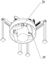
5. a first brake drum clamping means; 5a, a rotating seat; 5b, a pneumatic three-jaw chuck; 5c, a fixture block; 5d, a synchronous belt transmission mechanism; 5e, a servo motor;
6. processing a positioning mechanism; 6a, mounting plates; 6b, a cylinder; 6c, a point-contact sensor;
7. a paint spraying mechanism; 7a, a first portal frame; 7b, a first ball screw sliding table; 7c, a first mounting frame; 7d, a paint spraying box; 7d1, strip-shaped mouth; 7e, a spray gun; 7f, a cover ring;
8. a marking mechanism; 8a, a second portal frame; 8b, a second ball screw sliding table; 8c, a third ball screw sliding table; 8d, a second mounting frame; 8e, marking a head;
9. a finished product discharging mechanism; 9a, a third portal frame; 9b, a lifting slewing mechanism; 9c, a first pneumatic clamping jaw; 9d, a second pneumatic clamping jaw; 9e, a second belt conveyor;
10. and (5) finishing the brake drum.
Detailed Description
In order to make the objects, technical solutions and advantages of the present invention more apparent, the present invention is described in further detail below with reference to the accompanying drawings and embodiments. It should be understood that the specific embodiments described herein are merely illustrative of the invention and are not intended to limit the invention.
In the description of the present invention, it should be noted that the terms "center", "upper", "lower", "left", "right", "front", "rear", "vertical", "horizontal", "inner", "outer", and the like indicate orientations or positional relationships based on those shown in the drawings, and are only for convenience of description and simplicity of description, but do not indicate or imply that the referred device or element must have a specific orientation, be constructed in a specific orientation, and be operated, and thus, should not be construed as limiting the present invention. Furthermore, the terms "first," "second," and "third" are used for descriptive purposes only and are not to be construed as indicating or implying relative importance.
Referring to fig. 2 to 12, the automatic forming machine for the steel seal marks of the brake drum comprises a brake drum feeding mechanism 1, an industrial robot 2, a milling mechanism 3, an operation platform 4, a first brake drum clamping tool 5, a processing and positioning mechanism 6, a paint spraying mechanism 7, a marking mechanism 8, a finished product discharging mechanism 9 and an industrial computer, wherein the operation platform 4 comprises a hollow rotary disk 4a and a fixed disk 4b, the hollow rotary disk 4a is coaxially and rotatably arranged on the fixed disk 4b, the first brake drum clamping tool 5 is divided into four stations and axially and uniformly distributed on the hollow rotary disk 4a in a rotating manner, the processing and positioning mechanism 6 is arranged on the fixed disk 4b, the working end of the processing and positioning mechanism faces towards the first station, the transmission direction of the brake drum feeding mechanism 1 faces towards the milling mechanism 3, the industrial robot 2 comprises a first clamping jaw robot 2a and a second clamping jaw robot 2b, and the first clamping jaw robot 2a and the second clamping jaw robot 2b are respectively arranged on the brake drum feeding mechanism 1 and the milling mechanism 3, the milling mechanism Between the first station, second clamping jaw robot 2b, the mechanism 7 that sprays paint, marking mechanism 8 and finished product shedding mechanism 9 set gradually in hollow turntable 4 a's the outside one side of quadruplex position, brake drum feed mechanism 1, mill mechanism 3, processing positioning mechanism 6, the mechanism 7 that sprays paint, marking mechanism 8, finished product shedding mechanism 9 all are connected with the industrial computer electricity.
The industrial computer controls the brake drum feeding mechanism, the milling mechanism, the processing positioning mechanism, the paint spraying mechanism, the marking mechanism and the finished product discharging mechanism to work normally, after the work starts, the wide opening of the brake drum is downwards automatically fed by the brake drum feeding mechanism 1, so that the industrial robot 2 can send the unprocessed brake drum to the milling mechanism 3, namely the brake drum is clamped and sent to a workbench of the milling mechanism 3 at the feeding end of the brake drum feeding mechanism 1 through a first clamping jaw robot 2a, the bottom end of the brake drum is positioned and milled by the working end of the milling mechanism 3, after the milling is finished, the brake drum with the steel seal groove is clamped and sent to a first brake drum clamping tool 5 positioned on a first station through a second clamping jaw robot 2b, the brake drum is clamped and sent to the first brake drum clamping tool 5 positioned on the first station, the brake drum is clamped by the first brake drum clamping tool 5, so that the processing positioning mechanism 6 positioned on the first station positions the steel seal of the brake drum, in the positioning process, the first brake drum clamping tool 5 coaxially rotates, so that the steel seal groove is ensured to be outward along the radial direction of the operation table 4 all the time in the subsequent processing state, the subsequent processing success is ensured, after the positioning is finished, the hollow rotary disc 4a coaxially rotates relative to the fixed disc 4b, so that the first brake drum clamping tool 5 arranged on the first station clamps the brake drum to move to the second station, the steel seal groove of the brake drum is sprayed with paint through the paint spraying mechanism 7 arranged on the second station, after the paint spraying is finished, the working end of the paint spraying mechanism 7 resets, the hollow rotary disc 4a continuously coaxially rotates relative to the fixed disc 4b, so that the painted brake drum moves to the third station, the marking mechanism 8 arranged on the third station marks the steel seal groove of the brake drum, after the paint spraying is finished, the working end of the marking mechanism 8 resets, the hollow rotary disc 4a continuously coaxially rotates relative to the fixed disc 4b, thereby make the finished product of beating the mark completion remove to the fourth station, loosen the finished product at the first brake drum clamping tool 5 working segment of fourth station to make finished product discharge mechanism 9 can take off the finished product from the fourth station, thereby be convenient for collect, after the uninstallation, the first brake drum clamping tool 5 that is in the uninstallation state removes to first station again, thereby realizes reciprocal mark production.
The hollow rotary table 4a is uniformly provided with four mounting grooves 4a1 along the axial direction; first brake drum clamping tools 5 is including swivel mount 5a, pneumatic three-jaw chuck 5b, fixture block 5c, synchronous belt drive mechanism 5d and servo motor 5e, swivel mount 5a rotates and sets up in mounting groove 4a1, the transmission of synchronous belt drive mechanism 5d and servo motor 5e is passed through to swivel mount 5a bottom and is connected, the coaxial setting of pneumatic three-jaw chuck 5b is on swivel mount 5a top, pneumatic three-jaw chuck 5b work end is vertical up, fixture block 5c is fixed to be set up on pneumatic three-jaw chuck 5b work clamping jaw.
The hollow rotary disc 4a coaxially rotates relative to the fixed disc 4b, thereby realizing different labor division, opening and closing of the working end 5b before feeding, so that the distance from the fixture block 5c to the axis is larger than the radius of the brake drum, thereby facilitating the brake drum to fall onto the three-jaw chuck 5b, thereby facilitating the clamping block 5c to clamp the brake drum, the brake drum is loaded at the first station at one side of the hollow turntable 4a and is clamped by driving the pneumatic three-jaw chuck 5b, so that the clamping block 5c clamps the outer circumferential surface of the brake drum, thereby facilitating painting and marking, and the rotary seat 5a is rotatably provided on the mounting groove 4a1, and the bottom end of the rotating seat 5a is in transmission connection with a servo motor 5e through a synchronous belt transmission mechanism 5d, thereby make when fixing a position, the brake drum gesture can be adjusted to rotatory roating seat 5a for the brake drum steel bay is radial outside always, thereby is convenient for to steel bay department accurate spray paint and beat the mark.
The brake drum feeding mechanism 1 comprises a first belt conveyor 1a and a photoelectric sensor 1b, the first belt conveyor 1a is arranged on one side of the milling mechanism 3, a feeding end of the first belt conveyor 1a faces a feeding end of the milling mechanism 3, and a working end of the photoelectric sensor 1b is radially arranged at the feeding end of the first belt conveyor 1 a.
The brake drum is sent to the discharge gate from first belt conveyor 1a pan feeding mouth, when photoelectric sensor 1b detects when the brake drum, first belt conveyor 1a stop work to make it can mill mechanism 3 one side material loading, when the brake drum is got to press from both sides and is got milling mechanism 3, photoelectric sensor 1b does not detect that the pay-off end of first belt conveyor 1a has the brake drum, thereby makes first belt conveyor 1a continue to work, thereby ensures that the pay-off end of first belt conveyor 1a has the brake drum always.
The milling mechanism 3 comprises a milling machine 3a, a second brake drum clamping tool 3b, a positioning device 3c and a clamping tool fixing device 3d, the milling machine 3a is arranged on one side of a first station of an operation table 4, the second brake drum clamping tool 3b is arranged on a workbench of the milling machine 3a, the second brake drum clamping tool 3b and the first brake drum clamping tool 5 are identical in structure, the positioning device 3c is arranged at the working end of the second brake drum clamping tool 3b, in the working state, the positioning device 3c does not rotate along with the second brake drum clamping tool 3b, the clamping tool fixing device 3d is arranged at one end of the workbench, and the working end of the clamping tool fixing device 3d surrounds the bottom end of the second brake drum clamping tool 3 b.
The distance from the oil notch of the brake drum to the axis is equal to the distance from the working end of the positioning device 3c to the axis, the brake drum is sent to the milling machine 3a, firstly, the second brake drum clamping tool 3b clamps the brake drum, and the second brake drum clamping tool 3b and the first brake drum clamping tool 5 are completely the same in structure, so that the second brake drum clamping tool 3b clamps the brake drum to rotate on the workbench of the milling machine 3a, after the brake drum rotates for a certain angle, when the working end of the positioning device 3c detects an oil groove, the milling machine 3a stops rotating, so that the clamping tool fixing device 3d clamps the bottom end of the second brake drum clamping tool 3b, the displacement generated in the milling process is prevented, the milling is more accurate, the working end of the milling machine 3a descends, and the bottom end of the brake drum is milled to form an embossed groove.
The positioning device 3c comprises a mounting base 3c1, an extension shaft 3c2, a mounting column 3c3 and an infrared sensor 3c4, wherein the mounting base 3c1 is arranged inside the bottom end of the milling machine 3a, the extension shaft 3c2 coaxially penetrates through the second brake drum clamping tool 3b, the mounting column 3c3 is coaxially arranged at the top end of the extension shaft 3c2, the infrared sensor 3c4 is axially arranged inside the mounting column 3c3, the working end of the infrared sensor 3c4 is vertically arranged upwards, and the distance from the working end of the infrared sensor 3c4 to the axis is equal to the distance from the brake drum oil notch to the axis.
The distance from the working end of the infrared sensor 3c4 to the axis is equal to the distance from the brake drum oil notch to the axis, so that the brake drum rotates together with the second brake drum clamping tool 3b during rotation, the mounting base 3c1 is arranged inside the bottom end of the milling machine 3a, the extension shaft 3c2 coaxially penetrates through the second brake drum clamping tool 3b, the mounting column 3c3 is coaxially arranged at the top end of the extension shaft 3c2, so that the infrared sensor 3c4 is static relative to the brake drum, so that when the oil notch on the brake drum moves to the top end of the working end of the infrared sensor 3c4, the infrared sensor 3c4 does not detect an obstacle above, and the milling position is determined by sending a signal to an industrial computer and controlling the second brake drum clamping tool 3b to stop rotating.
The mounting plate 6a is radially arranged on the fixing column 4b1, the cylinder 6b is arranged at the bottom end of one side of the mounting plate 6a, so that the working end of the cylinder 6b can move to a first station relative to the mounting plate 6a, when the brake drum is placed at the first station, the steel seal position is random, the steel seal position needs to be determined, the subsequent processing is completed, the working end of the cylinder 6b descends, so that the working end of the point contact type sensor 6c is abutted against the top end of the brake drum, then the first brake drum clamping tool 5 on the first station drives the brake drum to rotate, in the rotating process, when the point contact type sensor 6c is in point contact with one side of the groove, the point contact type sensor continues to rotate, so that the other side of the groove is abutted against, so that the distance between the two sides of the groove is judged by an industrial computer, the distance between the oil groove and the two sides of the steel seal groove is shorter, so that whether the steel seal groove, so that the brake drum embossed groove is always radially outward.
First portal frame 7a sets up in 4 second station one sides of operation panel, the vertical setting of first ball screw slip table 7b is on first portal frame 7a top, thereby make when the brake drum that the location was accomplished removes to the second station, first ball screw slip table 7b working end drives first mounting bracket 7c and the box 7d that sprays paint descends, thereby make and install the apron 7f butt at the brake drum top in the box 7d bottom that sprays paint, thereby make the vertical plane of projection of bar mouth 7d1 and the coincidence of brake drum embossed seal groove, then spray gun 7e sprays paint to embossed seal groove department.
Second portal frame 8a sets up in 4 third stations one side of operation panel, second ball screw slip table 8b level sets up on second portal frame 8a top, the vertical setting of third ball screw slip table 8c is at the work end of second ball screw slip table 8b, thereby be convenient for beat the mark about from top to bottom, when the brake drum that the completion of spraying paint moves to the third station, third ball screw slip table 8c work end drives second mounting bracket 8d and beats mark head 8e downstream, thereby make and beat mark head 8e and can beat mark to brake drum embossed seal groove department.
The finished product unloading mechanism 9 comprises a third portal frame 9a, a lifting swing mechanism 9b, a first pneumatic clamping jaw 9c, a second pneumatic clamping jaw 9d and a second belt conveyor 9e, the second belt conveyor 9e is arranged on one side of the outer portion of the fourth station of the operation table 4 along the radial direction, the third portal frame 9a is arranged between the fourth station of the operation table 4 and the second belt conveyor 9e, the lifting swing mechanism 9b is arranged at the top end of the third portal frame 9a, the first pneumatic clamping jaw 9c and the second pneumatic clamping jaw 9d are respectively arranged on two sides of the bottom of the lifting swing mechanism 9b, and the first pneumatic clamping jaw 9c and the second pneumatic clamping jaw 9d respectively face the feeding end of the fourth station of the operation table 4 and the second belt conveyor 9 e.
The third portal frame 9a is arranged between the fourth station of the operation table 4 and the second belt conveyor 9e, the lifting and turning mechanism 9b is arranged at the top end of the third portal frame 9a, and after the finished product moves to the fourth station, the finished product is freely lifted and turned by the lifting and turning mechanism 9b, so that the finished product is clamped and sent from the fourth station to the second belt conveyor 9e by the first pneumatic clamping jaws 9c or the second pneumatic clamping jaws 9d, and the finished product is conveyed to a designated place by the second belt conveyor 9 e.
The hollow rotary disc 4a further comprises a placing stabilizer 4a2, the placing stabilizer 4a2 is coaxially arranged at the clamping end of the first brake drum clamping tool 5, and the bottom end of the placing stabilizer 4a2 penetrates through the first brake drum clamping tool 5 to be fixedly connected with the hollow rotary disc 4 a.
Place stabilizer 4a2 coaxial setting and press from both sides the end at first brake drum clamping tool 5, place stabilizer 4a2 bottom and run through first brake drum clamping tool 5 and hollow rotary disk 4a fixed connection to make when placing the brake drum, the brake drum can the back-off place stabilizer 4a2 on, thereby ensure the stability of follow-up course of working.
The working principle of the invention is as follows:
the industrial computer controls the brake drum feeding mechanism, the milling mechanism, the processing positioning mechanism, the paint spraying mechanism, the marking mechanism and the finished product discharging mechanism to work normally, after the work starts, the wide opening of the brake drum is downwards automatically fed by the brake drum feeding mechanism 1, so that the industrial robot 2 can send the unprocessed brake drum to the milling mechanism 3, namely the brake drum is clamped and sent to a workbench of the milling mechanism 3 at the feeding end of the brake drum feeding mechanism 1 through a first clamping jaw robot 2a, the bottom end of the brake drum is positioned and milled by the working end of the milling mechanism 3, after the milling is finished, the brake drum with the steel seal groove is clamped and sent to a first brake drum clamping tool 5 positioned on a first station through a second clamping jaw robot 2b, the brake drum is clamped and sent to the first brake drum clamping tool 5 positioned on the first station, the brake drum is clamped by the first brake drum clamping tool 5, so that the processing positioning mechanism 6 positioned on the first station positions the steel seal of the brake drum, in the positioning process, the first brake drum clamping tool 5 coaxially rotates, so that the steel seal groove is ensured to be outward along the radial direction of the operation table 4 all the time in the subsequent processing state, the subsequent processing success is ensured, after the positioning is finished, the hollow rotary disc 4a coaxially rotates relative to the fixed disc 4b, so that the first brake drum clamping tool 5 arranged on the first station clamps the brake drum to move to the second station, the steel seal groove of the brake drum is sprayed with paint through the paint spraying mechanism 7 arranged on the second station, after the paint spraying is finished, the working end of the paint spraying mechanism 7 resets, the hollow rotary disc 4a continuously coaxially rotates relative to the fixed disc 4b, so that the painted brake drum moves to the third station, the marking mechanism 8 arranged on the third station marks the steel seal groove of the brake drum, after the paint spraying is finished, the working end of the marking mechanism 8 resets, the hollow rotary disc 4a continuously coaxially rotates relative to the fixed disc 4b, thereby make the finished product of beating the mark completion remove to the fourth station, loosen the finished product at the first brake drum clamping tool 5 working segment of fourth station to make finished product discharge mechanism 9 can take off the finished product from the fourth station, thereby be convenient for collect, after the uninstallation, the first brake drum clamping tool 5 that is in the uninstallation state removes to first station again, thereby realizes reciprocal mark production.
Claims (7)
1. An automatic molding machine for brake drum steel seal marks is characterized by comprising a brake drum feeding mechanism (1), an industrial robot (2), a milling mechanism (3), an operating platform (4), a first brake drum clamping tool (5), a processing and positioning mechanism (6), a paint spraying mechanism (7), a marking mechanism (8), a finished product discharging mechanism (9) and an industrial computer, wherein the operating platform (4) comprises a hollow turntable (4 a) and a fixed disk (4 b), the hollow turntable (4 a) is coaxially and rotatably arranged on the fixed disk (4 b), the first brake drum clamping tool (5) is uniformly distributed on the hollow turntable (4 a) in a four-station axial rotating mode, the processing and positioning mechanism (6) is arranged on the fixed disk (4 b) and the working end of the processing and positioning mechanism faces towards the first station, the milling mechanism (3), the paint spraying mechanism (7), the marking mechanism (8) and the finished product discharging mechanism (9) are sequentially arranged on one side of the four stations of the hollow turntable (4 a), the conveying direction of the brake drum feeding mechanism (1) faces the milling mechanism (3), the industrial robot (2) comprises a first clamping jaw robot (2 a) and a second clamping jaw robot (2 b), the first clamping jaw robot (2 a) and the second clamping jaw robot (2 b) are respectively arranged between the brake drum feeding mechanism (1) and the milling mechanism (3) and between the milling mechanism (3) and a first station, and the mechanisms are electrically connected with an industrial computer;
four mounting grooves (4 a 1) are uniformly distributed on the hollow rotary disc (4 a) along the axial direction; the first brake drum clamping tool (5) comprises a rotary seat (5 a), a pneumatic three-jaw chuck (5 b), a clamping block (5 c), a synchronous belt transmission mechanism (5 d) and a servo motor (5 e), wherein the rotary seat (5 a) is rotatably arranged in a mounting groove (4 a 1), the bottom end of the rotary seat (5 a) is in transmission connection with the servo motor (5 e) through the synchronous belt transmission mechanism (5 d), the pneumatic three-jaw chuck (5 b) is coaxially arranged at the top end of the rotary seat (5 a), the working end of the pneumatic three-jaw chuck (5 b) is vertically upward, and the clamping block (5 c) is fixedly arranged on a working clamping jaw of the pneumatic three-jaw chuck (5 b);
the brake drum feeding mechanism (1) comprises a first belt conveyor (1 a) and a photoelectric sensor (1 b), the first belt conveyor (1 a) is arranged on one side of the milling mechanism (3), the feeding end of the first belt conveyor (1 a) faces the feeding end of the milling mechanism (3), and the working end of the photoelectric sensor (1 b) is arranged at the feeding end of the first belt conveyor (1 a) along the radial direction;
the milling mechanism (3) comprises a milling machine (3 a), a second brake drum clamping tool (3 b), a positioning device (3 c) and a clamping tool fixing device (3 d), the milling machine (3 a) is arranged on one side of a first station of an operation table (4), the second brake drum clamping tool (3 b) is arranged on a workbench of the milling machine (3 a), the second brake drum clamping tool (3 b) and the first brake drum clamping tool (5) are completely identical in structure, the positioning device (3 c) is arranged at a working end of the second brake drum clamping tool (3 b), the positioning device (3 c) does not rotate along with the second brake drum clamping tool (3 b) in a working state, the clamping tool fixing device (3 d) is arranged at one end of the workbench, and the working end of the clamping tool fixing device (3 d) surrounds the bottom end of the second brake drum clamping tool (3 b).
2. The automatic brake drum steel seal mark forming machine according to claim 1, wherein the positioning device (3 c) comprises a mounting base (3 c 1), an extension shaft (3 c 2), a mounting column (3 c 3) and an infrared sensor (3 c 4), the mounting base (3 c 1) is arranged inside the bottom end of the milling machine (3 a), the extension shaft (3 c 2) coaxially penetrates through the second brake drum clamp (3 b), the mounting column (3 c 3) is coaxially arranged at the top end of the extension shaft (3 c 2), the infrared sensor (3 c 4) is axially arranged inside the mounting column (3 c 3), the working end of the infrared sensor (3 c 4) is vertically arranged upwards, and the distance from the working end of the infrared sensor (3 c 4) to the axis is equal to the distance from the oil notch of the brake drum to the axis.
3. The automatic brake drum steel seal mark forming machine according to claim 1, wherein a fixed column (4 b 1) is coaxially arranged at the top end of the fixed disc (4 b), the processing and positioning mechanism (6) comprises a mounting plate (6 a), an air cylinder (6 b) and a point contact type sensor (6 c), the mounting plate (6 a) is radially arranged on the fixed column (4 b 1), the air cylinder (6 b) is arranged at the bottom end of one side of the mounting plate (6 a), the point contact type sensor (6 c) is fixedly connected with the bottom end of the air cylinder (6 b) through a coupler, and the working end of the point contact type sensor (6 c) faces to the first station of the operating platform (4).
4. The automatic brake drum embossed mark forming machine according to claim 1, wherein the paint spraying mechanism (7) comprises a first portal frame (7 a), a first ball screw sliding table (7 b), a first mounting frame (7 c), a paint spraying box (7 d), a spray gun (7 e) and a cover ring (7 f), the first portal frame (7 a) is arranged on one side of the second station of the operation table (4), the first ball screw sliding table (7 b) is vertically arranged at the top end of the first portal frame (7 a), the first mounting frame (7 c) is arranged at the working end of the first ball screw sliding table (7 b), the paint spraying box (7 d) is arranged at the bottom end of the first mounting frame (7 c), a strip-shaped opening (7 d 1) matched with the embossed mark groove of the brake drum is arranged inside the paint spraying box (7 d), the spray gun (7 e) is arranged inside the paint spraying box (7 d), and the working end of the spray gun (7 e) faces to the strip-shaped opening (7 d 1), the cover ring (7 f) is coaxially arranged at the bottom end of the cover ring (7 f).
5. The automatic molding machine for the brake drum steel seal marks according to claim 1, wherein the marking mechanism (8) comprises a second portal frame (8 a) and a second ball screw sliding table (8 b), third ball screw slip table (8 c), second mounting bracket (8 d) and mark (8 e) of marking, second portal frame (8 a) set up in operation panel (4) third station one side, second ball screw slip table (8 b) level sets up on second portal frame (8 a) top, the vertical work end that sets up at second ball screw slip table (8 b) of third ball screw slip table (8 c), second mounting bracket (8 d) set up at third ball screw slip table (8 c) work end, mark (8 e) set up the bottom in second mounting bracket (8 d), mark (8 e) work end is vertical towards operation panel (4) third station.
6. The automatic molding machine for steel seal marks of brake drums as defined in claim 1, wherein the finished product unloading mechanism (9) comprises a third portal frame (9 a), a lifting and turning mechanism (9 b), a first pneumatic clamping jaw (9 c), a second pneumatic clamping jaw (9 d) and a second belt conveyor (9 e), the second belt conveyor (9 e) is radially arranged at one side of the fourth station of the operation table (4), the third portal frame (9 a) is arranged between the fourth station of the operation table (4) and the second belt conveyor (9 e), the lifting and turning mechanism (9 b) is arranged at the top end of the third portal frame (9 a), the first pneumatic clamping jaw (9 c) and the second pneumatic clamping jaw (9 d) are respectively arranged at two sides of the bottom of the lifting and turning mechanism (9 b), the first pneumatic clamping jaw (9 c) and the second pneumatic clamping jaw (9 d) face to the fourth station of the operating platform (4) and the feeding end of the second belt conveyor (9 e) respectively.
7. The automatic molding machine for brake drum steel seal marks according to claim 1, wherein the hollow rotary disc (4 a) further comprises a placing stabilizer (4 a 2), the placing stabilizer (4 a 2) is coaxially arranged at the clamping end of the first brake drum clamp (5), and the bottom end of the placing stabilizer (4 a 2) penetrates through the first brake drum clamp (5) and is fixedly connected with the hollow rotary disc (4 a).
Priority Applications (1)
| Application Number | Priority Date | Filing Date | Title |
|---|---|---|---|
| CN202011083572.2A CN112355366A (en) | 2020-01-10 | 2020-01-10 | Automatic forming machine for steel seal marks of brake drums |
Applications Claiming Priority (2)
| Application Number | Priority Date | Filing Date | Title |
|---|---|---|---|
| CN202011083572.2A CN112355366A (en) | 2020-01-10 | 2020-01-10 | Automatic forming machine for steel seal marks of brake drums |
| CN202010025136.3A CN111112708B (en) | 2020-01-10 | 2020-01-10 | Automatic forming machine for steel seal marks of brake drums |
Related Parent Applications (1)
| Application Number | Title | Priority Date | Filing Date |
|---|---|---|---|
| CN202010025136.3A Division CN111112708B (en) | 2020-01-10 | 2020-01-10 | Automatic forming machine for steel seal marks of brake drums |
Publications (1)
| Publication Number | Publication Date |
|---|---|
| CN112355366A true CN112355366A (en) | 2021-02-12 |
Family
ID=70487722
Family Applications (2)
| Application Number | Title | Priority Date | Filing Date |
|---|---|---|---|
| CN202010025136.3A Active CN111112708B (en) | 2020-01-10 | 2020-01-10 | Automatic forming machine for steel seal marks of brake drums |
| CN202011083572.2A Withdrawn CN112355366A (en) | 2020-01-10 | 2020-01-10 | Automatic forming machine for steel seal marks of brake drums |
Family Applications Before (1)
| Application Number | Title | Priority Date | Filing Date |
|---|---|---|---|
| CN202010025136.3A Active CN111112708B (en) | 2020-01-10 | 2020-01-10 | Automatic forming machine for steel seal marks of brake drums |
Country Status (1)
| Country | Link |
|---|---|
| CN (2) | CN111112708B (en) |
Families Citing this family (1)
| Publication number | Priority date | Publication date | Assignee | Title |
|---|---|---|---|---|
| CN114083140B (en) * | 2022-01-14 | 2022-04-08 | 河钢工业技术服务有限公司 | Laser and spraying cooperative multi-mode marking method and device |
Citations (11)
| Publication number | Priority date | Publication date | Assignee | Title |
|---|---|---|---|---|
| JP2002126928A (en) * | 2000-10-26 | 2002-05-08 | Amada Co Ltd | Deburring method and deburring system |
| CN203765406U (en) * | 2014-04-18 | 2014-08-13 | 广东和氏自动化技术有限公司 | Integrated flange deburring and checking machine |
| CN204108362U (en) * | 2014-07-04 | 2015-01-21 | 枣庄海纳科技有限公司 | A kind of ring flange bores milling special purpose machine tool |
| CN205058862U (en) * | 2015-10-24 | 2016-03-02 | 厦门文天数码机械有限公司 | Clean marking machine of multistation LED lamp |
| CN207087314U (en) * | 2017-05-24 | 2018-03-13 | 浙江兴三星五金有限公司 | Porous part automatic multi-station tapping device with automatic deviation rectifying function |
| CN207138948U (en) * | 2017-09-21 | 2018-03-27 | 平湖市高鑫自动化设备科技有限公司 | A kind of milling attachment of case fan |
| CN207757220U (en) * | 2017-12-18 | 2018-08-24 | 长春英利汽车工业有限公司 | Tyre-well robot flame treatment japanning Pneumatic marking knows work station |
| CN207857926U (en) * | 2018-02-05 | 2018-09-14 | 昆明裕恒汽车配件制造有限公司 | A kind of continuous milling machine for automobile brake drum production |
| CN108927558A (en) * | 2018-08-23 | 2018-12-04 | 佘娟 | A kind of outer circle milling automatic device of crankshaft-link rod head |
| CN109986364A (en) * | 2019-04-03 | 2019-07-09 | 郧西精诚汽配有限公司 | A kind of differential casing automatic production line |
| CN110587289A (en) * | 2019-09-16 | 2019-12-20 | 浙江志达管业有限公司 | Pipe fitting processing equipment for blasting test |
Family Cites Families (4)
| Publication number | Priority date | Publication date | Assignee | Title |
|---|---|---|---|---|
| JP2004129501A (en) * | 2002-10-08 | 2004-04-30 | Minami Shokuhin:Kk | Apparatus for cutting fish body and method for cutting fish body |
| CN202097630U (en) * | 2011-05-18 | 2012-01-04 | 上海经一木汇自动化设备有限公司 | Deburring machine for synchronous gears |
| CN105965267B (en) * | 2016-05-25 | 2019-06-07 | 佛山市成达液压设备有限公司 | Metal pot forming equipment |
| CN209014370U (en) * | 2018-08-31 | 2019-06-21 | 天津市长龙宏业燃气设备有限公司 | Steel cylinder steel seal labelled notation device |
-
2020
- 2020-01-10 CN CN202010025136.3A patent/CN111112708B/en active Active
- 2020-01-10 CN CN202011083572.2A patent/CN112355366A/en not_active Withdrawn
Patent Citations (11)
| Publication number | Priority date | Publication date | Assignee | Title |
|---|---|---|---|---|
| JP2002126928A (en) * | 2000-10-26 | 2002-05-08 | Amada Co Ltd | Deburring method and deburring system |
| CN203765406U (en) * | 2014-04-18 | 2014-08-13 | 广东和氏自动化技术有限公司 | Integrated flange deburring and checking machine |
| CN204108362U (en) * | 2014-07-04 | 2015-01-21 | 枣庄海纳科技有限公司 | A kind of ring flange bores milling special purpose machine tool |
| CN205058862U (en) * | 2015-10-24 | 2016-03-02 | 厦门文天数码机械有限公司 | Clean marking machine of multistation LED lamp |
| CN207087314U (en) * | 2017-05-24 | 2018-03-13 | 浙江兴三星五金有限公司 | Porous part automatic multi-station tapping device with automatic deviation rectifying function |
| CN207138948U (en) * | 2017-09-21 | 2018-03-27 | 平湖市高鑫自动化设备科技有限公司 | A kind of milling attachment of case fan |
| CN207757220U (en) * | 2017-12-18 | 2018-08-24 | 长春英利汽车工业有限公司 | Tyre-well robot flame treatment japanning Pneumatic marking knows work station |
| CN207857926U (en) * | 2018-02-05 | 2018-09-14 | 昆明裕恒汽车配件制造有限公司 | A kind of continuous milling machine for automobile brake drum production |
| CN108927558A (en) * | 2018-08-23 | 2018-12-04 | 佘娟 | A kind of outer circle milling automatic device of crankshaft-link rod head |
| CN109986364A (en) * | 2019-04-03 | 2019-07-09 | 郧西精诚汽配有限公司 | A kind of differential casing automatic production line |
| CN110587289A (en) * | 2019-09-16 | 2019-12-20 | 浙江志达管业有限公司 | Pipe fitting processing equipment for blasting test |
Also Published As
| Publication number | Publication date |
|---|---|
| CN111112708A (en) | 2020-05-08 |
| CN111112708B (en) | 2020-12-08 |
Similar Documents
| Publication | Publication Date | Title |
|---|---|---|
| CN108890127B (en) | Welding equipment for automobile safety airbag generator | |
| CN201208678Y (en) | Automatic welding machine | |
| CN107511726B (en) | Automatic change equipment of grinding blank | |
| CN110125757B (en) | Deburring device for lower swing arm casting of automobile | |
| CN109551318A (en) | Hub for vehicle wheel polishing system | |
| CN210849361U (en) | Automatic loading and unloading device of machine tool | |
| CN111168216B (en) | Automatic mounting spot welding machine for brake drum partition plate | |
| CN111112708B (en) | Automatic forming machine for steel seal marks of brake drums | |
| CN111151906B (en) | Compressor assembly welding production line and control method | |
| CN210121572U (en) | Automatic outer diameter adjusting and detecting device for drum brake | |
| CN206445415U (en) | A kind of fixture welded for car floor | |
| US4667805A (en) | Robotic part presentation system | |
| JPH0825088A (en) | Positioner tuilting device for welding robot | |
| CN217619047U (en) | Automatic welding system of PD wheel | |
| CN115922067A (en) | Welding device and processing equipment | |
| CN107363341A (en) | A kind of slot rolling production line of hub nut socket end | |
| CN213764386U (en) | Full-automatic multi-angle arc welding device of robot | |
| CN112045475B (en) | Machining system and machining method for manufacturing automobile parts | |
| CN211807912U (en) | Single-workpiece feeding ultrasonic plastic welding machine | |
| CN210997738U (en) | Automatic loading and unloading device for machining flange hole of automobile bearing | |
| CN109773614B (en) | Chamfering machine and chamfering method | |
| CN216939069U (en) | Welding workstation | |
| CN214277941U (en) | Automatic detection marking device for end plate welding seam | |
| CN220881081U (en) | Multi-station welding mechanism of robot | |
| CN215546357U (en) | Welding jig that can overturn |
Legal Events
| Date | Code | Title | Description |
|---|---|---|---|
| PB01 | Publication | ||
| PB01 | Publication | ||
| SE01 | Entry into force of request for substantive examination | ||
| SE01 | Entry into force of request for substantive examination | ||
| WW01 | Invention patent application withdrawn after publication |
Application publication date: 20210212 |
|
| WW01 | Invention patent application withdrawn after publication |