CN112353061B - Non-shifting conveying device for shoe production - Google Patents
Non-shifting conveying device for shoe production Download PDFInfo
- Publication number
- CN112353061B CN112353061B CN202011258298.8A CN202011258298A CN112353061B CN 112353061 B CN112353061 B CN 112353061B CN 202011258298 A CN202011258298 A CN 202011258298A CN 112353061 B CN112353061 B CN 112353061B
- Authority
- CN
- China
- Prior art keywords
- conveying
- block
- plate
- inclined triangular
- triangular block
- Prior art date
- Legal status (The legal status is an assumption and is not a legal conclusion. Google has not performed a legal analysis and makes no representation as to the accuracy of the status listed.)
- Active
Links
Images


Classifications
-
- A—HUMAN NECESSITIES
- A43—FOOTWEAR
- A43D—MACHINES, TOOLS, EQUIPMENT OR METHODS FOR MANUFACTURING OR REPAIRING FOOTWEAR
- A43D111/00—Shoe machines with conveyors for jacked shoes or for shoes or shoe parts
- A43D111/003—Shoe machines with conveyors for jacked shoes or for shoes or shoe parts with clamping or gripping mechanism
-
- Y—GENERAL TAGGING OF NEW TECHNOLOGICAL DEVELOPMENTS; GENERAL TAGGING OF CROSS-SECTIONAL TECHNOLOGIES SPANNING OVER SEVERAL SECTIONS OF THE IPC; TECHNICAL SUBJECTS COVERED BY FORMER USPC CROSS-REFERENCE ART COLLECTIONS [XRACs] AND DIGESTS
- Y02—TECHNOLOGIES OR APPLICATIONS FOR MITIGATION OR ADAPTATION AGAINST CLIMATE CHANGE
- Y02P—CLIMATE CHANGE MITIGATION TECHNOLOGIES IN THE PRODUCTION OR PROCESSING OF GOODS
- Y02P70/00—Climate change mitigation technologies in the production process for final industrial or consumer products
- Y02P70/10—Greenhouse gas [GHG] capture, material saving, heat recovery or other energy efficient measures, e.g. motor control, characterised by manufacturing processes, e.g. for rolling metal or metal working
Landscapes
- Reciprocating Conveyors (AREA)
Abstract
The invention relates to the technical field of shoe flow production equipment, in particular to a non-shifting conveying device for shoe production, which comprises a conveying frame, wherein backing plates are symmetrically arranged on the front side and the rear side of an inner cavity of the conveying frame, a hydraulic cylinder is vertically arranged at the lower end of the middle position of the inner cavity of the conveying frame, a conveying belt is arranged at the upper end of the backing plate, conveying blocks which are linearly distributed are arranged on the conveying belt, chains are fixedly arranged on the outer walls of the front side and the rear side of the conveying belt, and the non-shifting conveying device has the advantages that: the invention realizes the extrusion fixation of the installation position of the sole plate by arranging the matching of the limiting top plate and the positioning column, thereby preventing the vibration offset generated in the conveying process, and simultaneously realizing the stable conveying by utilizing the clamping connection of the gear and the chain; through the buffer that sets up the triangle piece that has the slope, realize buffering the transmission impact force, utilize the joint of sawtooth to prevent to kick-back, through the cooperation of buffer beam and spring, realize carrying out further buffering to impact force and inertia to reach stable accurate location and stop.
Description
Technical Field
The invention relates to the technical field of shoe flow production equipment, in particular to a non-shifting conveying device for shoe production.
Background
Shoes are carrying out the in-process that sole and vamp bond, and in order to improve production efficiency, the mode that adopts flow production mostly assembles, in the production bonding process, realizes the fixed mounting of sole through location installation device, then utilizes the conveyer belt to transport location installation device to the bonding position.
In actual production process, because location installation device's transport is driven by the conveyer belt, because the vibration, the vibration skew appears in the shoe bottom plate that causes internally mounted very easily at the transmission in-process, and then causes bonding precision to reduce, simultaneously at the positioning process, because driven inertia effect, often causes positioner's stop position and the great deviation of bonding station appearance to need consume manpower resources and carry out iterative position control.
Therefore, the non-shifting conveying device for shoe production is provided, and the problems of vibration deviation and positioning stop in the conveying process of the shoe bottom plate are solved.
Disclosure of Invention
The present invention aims to provide a non-shifting transmission device for shoe production to solve the problems of the prior art.
In order to achieve the purpose, the invention provides the following technical scheme:
a non-displacement conveying device for shoe production comprises a conveying frame, wherein backing plates are symmetrically arranged on the front side and the rear side of an inner cavity of the conveying frame, a hydraulic cylinder is vertically arranged at the lower end of the middle position of the inner cavity of the conveying frame, a conveying belt is arranged at the upper end of the backing plates, conveying blocks which are linearly distributed are arranged on the conveying belt, chains are fixedly arranged on the outer walls of the front side and the rear side of the conveying belt, a downward-concave mounting groove is formed in the middle of the upper end face of each conveying block, a limiting side plate is vertically welded on the left side of the lower end of each conveying block, a sawtooth strip is arranged on the right side of the lower end face of each conveying block, a carrying plate is arranged at the lower end of the front end face of each conveying block, a sole plate is arranged in the inner cavity of the mounting groove, a limiting top plate is arranged in the inner cavity of the upper end of the mounting groove, a lifting block is arranged at the upper end of the hydraulic cylinder, a rotating support is vertically provided with a rotating inclined triangular block, a buffer rod is transversely arranged on the left side of the rotating support, a longitudinal spring is arranged at the lower end of the inclined triangular block, a transverse spring is arranged on the right side of the buffer rod, and a limiting block is sleeved on the left side of the buffer rod;
the chain is composed of a first chain plate and a second chain plate which are connected in a staggered mode, the first chain plate and the second chain plate are fixedly connected through a connecting bolt, rotating rollers distributed at intervals are rotatably installed in inner cavities of the first chain plate and the second chain plate, inserting key grooves penetrating up and down are formed in gaps between the rotating rollers distributed at intervals, teeth of spherical end portions distributed in a circumferential array mode are arranged on the driven gear, and the teeth are connected in the inner cavities of the inserting key grooves in an inserting mode.
Preferably, the backing plate is fixedly and vertically welded on the inner wall of the conveying frame, the lower end of the conveying belt is attached to the upper end face of the backing plate in a sliding mode, and the end portions of the left side and the right side of the conveying belt are rotatably provided with driving motors.
Preferably, the carrying plate extends to the outer side of the conveying block, the outer wall of the carrying plate extends to the front end part and the rear end part of the conveying belt, and the lower end of the carrying plate is attached to the upper end face of the conveying belt.
Preferably, four positioning columns distributed in a matrix mode are arranged at corners of the upper end face of the conveying block, the upper end of the limiting top plate is inserted into the outer walls of the positioning columns in a sliding mode, and the lower end of the limiting top plate abuts against the outer wall of the edge of the upper end of the sole plate.
Preferably, the inner wall of the lower end of the inner cavity of the mounting groove is provided with positioning inserting strips which are linearly distributed, the positioning inserting strips correspond to the anti-skid grooves in the lower end of the sole plate one to one, and the positioning inserting strips are inserted into the anti-skid grooves in the lower end of the sole plate.
Preferably, the longitudinal spring is vertically installed at the lower end of the right side of the inclined triangular block, the upper end of the longitudinal spring abuts against an inner cavity of the lower end of the inclined triangular block, and the lower end of the longitudinal spring abuts against the upper end face of the lifting block.
Preferably, the upper end of the right side of the inclined triangular block is positioned at the upper end of the lower end face of the conveying block, the lower end of the left side of the inclined triangular block is positioned between the right side of the limiting side plate and the lower end of the conveying block, and the inclined directions of the inclined triangular block and the inner sawteeth of the sawtooth strip are the same.
Preferably, the limiting side plate and the rotating support are arranged at equal height and transversely penetrate through a through hole, the buffer rod is inserted into the through hole in a sliding mode, the transverse spring is sleeved on the outer wall of the right side of the buffer rod, and two ends of the transverse spring respectively abut against the end screw cap of the buffer rod and the outer wall of the right side of the limiting side plate.
Compared with the prior art, the invention has the beneficial effects that:
1. the invention realizes the extrusion fixation of the installation position of the sole plate by arranging the matching of the limiting top plate and the positioning column, thereby preventing the vibration offset generated in the conveying process, and simultaneously realizing the stable conveying by utilizing the clamping connection of the gear and the chain;
2. the buffer device with the inclined triangular blocks is arranged to buffer the transmission impact force, the sawtooth is clamped to prevent springback, and the buffer rod is matched with the spring to further buffer the impact force and inertia, so that stable and accurate positioning and stopping are achieved.
Drawings
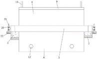
FIG. 1 is a schematic structural diagram of the present invention
FIG. 2 is a side view of a transfer block of the present invention;
FIG. 3 is a top view of the structure of a portion of the chain of the present invention;
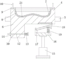
FIG. 4 is a front view of a buffer structure of a transport block according to the present invention;
fig. 5 is a diagram illustrating a buffer structure of a transport block according to the present invention.
In the figure: 1. a transfer frame; 2. a base plate; 3. a conveyor belt; 4. a transfer block; 5. building a support plate; 6. a limiting side plate; 7. mounting grooves; 8. a sole plate; 9. a limiting top plate; 10. a positioning column; 11. a sawtooth strip; 12. a buffer rod; 13. a lateral spring; 14. a limiting block; 15. a hydraulic cylinder; 16. a lifting block; 17. rotating the bracket; 18. inclining the triangular block; 19. a longitudinal spring; 20. a driven gear; 21. positioning the cutting; 22. a chain; 23. teeth; 24. a first link plate; 25. a second link plate; 26. a connecting bolt; 27. rotating the roller; 28. inserting a key slot; 29. a rotating shaft; 30. and a through hole.
Detailed Description
The technical solutions in the embodiments of the present invention will be clearly and completely described below with reference to the drawings in the embodiments of the present invention, and it is obvious that the described embodiments are only a part of the embodiments of the present invention, and not all of the embodiments. All other embodiments, which can be derived by a person skilled in the art from the embodiments given herein without making any creative effort, shall fall within the protection scope of the present invention.
Referring to fig. 1 to 5, the present invention provides a technical solution:
a non-displacement conveying device for shoe production comprises a conveying frame 1, wherein backing plates 2 are symmetrically arranged on the front side and the rear side of an inner cavity of the conveying frame 1, a conveying belt 3 is arranged at the upper end of each backing plate 2, conveying blocks 4 which are linearly distributed are arranged on the conveying belt 3, a carrying plate 5 is arranged at the lower end of the front end face of each conveying block 4, each backing plate 2 is fixedly and vertically welded on the inner wall of the conveying frame 1, the lower end of each conveying belt 3 is in sliding fit with the upper end face of each backing plate 2, driving motors are rotatably arranged at the end parts of the left side and the right side of each conveying belt 3, each carrying plate 5 extends to the outer side of each conveying block 4, and the outer wall of the carrying plate 5 extends to the front end part and the rear end part of the conveyor belt 3, the lower end of the carrying plate 5 is attached to the upper end surface of the conveyor belt 3, the purpose of position conveying is realized by the conveyor belt 3, and the position carrying of the conveying block 4 is realized by the matching of the carrying plate 5 and the base plate 2, so that the conveying block 4 is prevented from falling.
Be provided with undercut's mounting groove 7 in the middle of conveying block 4's the up end, the inner chamber of mounting groove 7 is provided with sole board 8, spacing roof 9 is installed to mounting groove 7's upper end inner chamber, conveying block 4's up end corner position is provided with four reference columns 10 of matrix distribution, the upper end of spacing roof 9 slides and pegs graft at reference column 10's outer wall, the lower extreme of spacing roof 9 supports the marginal outer wall of upper end at sole board 8, utilize spacing roof 9 and reference column 10's cooperation, the realization is to sole board 8's downward location extrusion, prevent to cause the offset owing to conveying vibration.
Be provided with linear distribution's location cutting 21 on the inner chamber lower extreme inner wall of mounting groove 7, location cutting 21 and the anti-skidding recess one-to-one of sole plate 8 lower extreme, and location cutting 21 pegs graft in the anti-skidding recess of sole plate 8 lower extreme, through the anti-skidding recess cooperation of location cutting 21 and sole plate 8 lower extreme, realize carrying out position fixing to sole plate 8, realize further position fixing.
The outer walls of the front side and the rear side of the conveyor belt 3 are fixedly provided with chains 22, the chains 22 are composed of first chain plates 24 and second chain plates 25 which are connected in a staggered manner, the first chain plates 24 are fixedly connected with the second chain plates 25 through connecting bolts 26, rotating rollers 27 which are distributed at intervals are rotatably arranged in inner cavities of the first chain plates 24 and the second chain plates 25, and the rotating rollers 27 which are distributed at intervals are used for realizing tangent connection of connecting surfaces, so that the teeth 23 can rotate smoothly.
The gap between the rotating rollers 27 distributed at intervals is provided with an inserting key groove 28 which penetrates through up and down, the outer walls of the front side and the rear side of the carrying plate 5 are rotatably inserted with a rotating shaft 29, the outer wall of the rotating shaft 29 is sleeved with a driven gear 20, the driven gear 20 is provided with teeth 23 with spherical end parts distributed in a circumferential array manner, the teeth 23 are inserted in the inner cavity of the inserting key groove 28, and the position of the conveying block 4 is limited by the matching of the teeth 23 and the inserting key groove 28.
The lower extreme of the inner chamber intermediate position of transfer frame 1 is vertical installs pneumatic cylinder 15, and the upper end of pneumatic cylinder 15 is provided with elevator 16, and the upper end left side of elevator 16 is vertical to be provided with rotates support 17, rotates to install the three hornblocks 18 that incline on the support 17, utilizes pneumatic cylinder 15 to realize rotating support 17, elevator 16 and the three hornblocks 18's of slope oscilaltion.
Vertical welding in lower extreme left side of transfer block 4 has spacing curb plate 6, the left side of rotating support 17 transversely is provided with buffer beam 12, the right side of buffer beam 12 is provided with horizontal spring 13, stopper 14 has been cup jointed in the left side of buffer beam 12, spacing curb plate 6 transversely runs through with the position such as rotating support 17 height and has seted up through-hole 30, buffer beam 12 slides and pegs graft in through-hole 30, horizontal spring 13 cup joints on the right side outer wall of buffer beam 12, the both ends of horizontal spring 13 support respectively on the tip nut of buffer beam 12 and on the right side outer wall of spacing curb plate 6, utilize through-hole 30 to realize the slip grafting of buffer beam 12, utilize stopper 14 to inject the position that buffer beam 12 moved right, utilize horizontal spring 13 to cushion the inertia of strikeing right, prevent to warp.
The right side of the lower end face of the conveying block 4 is provided with a sawtooth rack 11, the lower end of the inclined triangular block 18 is provided with a longitudinal spring 19, the longitudinal spring 19 is vertically installed at the lower end of the right side of the inclined triangular block 18, the upper end of the longitudinal spring 19 abuts against the inner cavity of the lower end of the inclined triangular block 18, the lower end of the longitudinal spring 19 abuts against the upper end face of the lifting block 16, the vertical spring 19 is used for buffering the downward extrusion force of the inclined triangular block 18, and therefore the inclined triangular block 18 always keeps upward extrusion force.
The right side upper end of slope triangle piece 18 is located conveying block 4 lower terminal surface upper end, and the left side lower extreme of slope triangle piece 18 is located between the right side of spacing curb plate 6 and the lower extreme of conveying block 4, and the slope direction of sawtooth is the same in slope triangle piece 18 and the sawtooth rack 11, through the slope grafting cooperation of slope triangle piece 18 with sawtooth rack 11, prevents because the rebound effect that the elasticity of transverse spring 13 caused to the position precision that stops has further been improved.
The working principle is as follows: at first utilize conveyer belt 3 to realize the purpose of position conveying, the cooperation that utilizes carrying board 5 and backing plate 2 realizes carrying on the position to conveying piece 4, prevent that conveying piece 4 from dropping, utilize the cooperation of spacing roof 9 and reference column 10, realize the extrusion of the downward location to sole board 8, prevent to cause the offset because of conveying vibration, through the cooperation of the anti-skidding recess of location cutting 21 with sole board 8 lower extreme, the realization carries out the rigidity to sole board 8, realize further rigidity.
In the transmission process, the tooth 23 is matched with the inserting key groove 28 to limit the position of the transmission block 4, when the transmission block 4 is in contact with the inclined triangular block 18, the transmission block 4 downwards extrudes the inclined triangular block 18 due to the trend of rightward movement, the longitudinal spring 19 is extruded at the moment, the downward extrusion force of the inclined triangular block 18 is buffered by the longitudinal spring 19, so that the inclined triangular block 18 always keeps upward extrusion force, the inclined triangular block 18 slides in the sawtooth rack 11 along with the deformation and the reduction of the longitudinal spring 19, the inclined triangular block 18 is in inserting fit with the inclination of the sawtooth rack 11, the rebound effect caused by the elastic force of the transverse spring 13 is prevented, and the stopping position precision is further improved.
Utilize through-hole 30 to realize the slip grafting of buffer lever 12, utilize stopper 14 to inject the position that buffer lever 12 moved right, utilize horizontal spring 13 to cushion the inertia of assaulting right, prevent to warp, buffer lever 12 supports on rotating bracket 17 this moment, along with right extrusion motion, horizontal spring 13 is compressed, make the pressfitting of slope triangle piece 18 at the tip of sawtooth rack 11, realize stably, accurate location stops, the stop back, the current motion of chain 22, make driven gear 20 realize the rotation under the transmission of sprocket.
After the processing is finished, the hydraulic cylinder 15 is utilized to realize the descending of the rotating bracket 17, the lifting block 16 and the inclined triangular block 18, so that the inclined triangular block 18 is separated from the sawtooth rack 11, and the purpose of flow line production is achieved.
The driving device and the mounting structure of the conveyor belt 3 are in the prior art and are not described in detail; the hydraulic cylinder 15 adopts the following models: SC series servo hydraulic cylinder.
Although embodiments of the present invention have been shown and described, it will be appreciated by those skilled in the art that changes, modifications, substitutions and alterations can be made in these embodiments without departing from the principles and spirit of the invention, the scope of which is defined in the appended claims and their equivalents.
Claims (1)
1. The utility model provides a not transfer device of shoes production usefulness, includes transfer frame (1), its characterized in that: backing plates (2) are symmetrically arranged on the front side and the rear side of an inner cavity of the conveying frame (1), a hydraulic cylinder (15) is vertically arranged at the lower end of the middle position of the inner cavity of the conveying frame (1), a conveying belt (3) is arranged at the upper end of the backing plate (2), conveying blocks (4) which are linearly distributed are arranged on the conveying belt (3), chains (22) are fixedly arranged on the outer walls of the front side and the rear side of the conveying belt (3), a mounting groove (7) which is downwards sunken is formed in the middle of the upper end face of each conveying block (4), a limiting side plate (6) is vertically welded on the left side of the lower end of each conveying block (4), a sawtooth strip (11) is arranged on the right side of the lower end face of each conveying block (4), a support plate (5) is arranged at the lower end face of the front side of each conveying block (4), a sole plate (8) is arranged in the inner cavity of each mounting groove (7), and a limiting top plate (9) is arranged in the inner cavity of each mounting groove (7), the hydraulic cylinder is characterized in that a lifting block (16) is arranged at the upper end of the hydraulic cylinder (15), a rotating support (17) is vertically arranged on the left side of the upper end of the lifting block (16), an inclined triangular block (18) is rotatably mounted on the rotating support (17), a buffer rod (12) is transversely arranged on the left side of the rotating support (17), a longitudinal spring (19) is arranged at the lower end of the inclined triangular block (18), a transverse spring (13) is arranged on the right side of the buffer rod (12), and a limiting block (14) is sleeved on the left side of the buffer rod (12);
the outer walls of the front side and the rear side of the carrying plate (5) are rotatably inserted with rotating shafts (29), the outer wall of each rotating shaft (29) is sleeved with a driven gear (20), each chain (22) is composed of a first chain plate (24) and a second chain plate (25) which are connected in a staggered mode, the first chain plates (24) and the second chain plates (25) are fixedly connected through connecting bolts (26), rotating rollers (27) which are distributed at intervals are rotatably installed in inner cavities of the first chain plates (24) and the second chain plates (25), inserting key grooves (28) which penetrate through up and down are arranged in gaps between the rotating rollers (27) which are distributed at intervals, teeth (23) of spherical end parts which are distributed in a circumferential array mode are arranged on the driven gear (20), and the teeth (23) are inserted in the inner cavities of the inserting key grooves (28);
the backing plate (2) is fixedly and vertically welded on the inner wall of the conveying frame (1), the lower end of the conveying belt (3) is attached to the upper end face of the backing plate (2) in a sliding mode, and the end portions of the left side and the right side of the conveying belt (3) are rotatably provided with driving motors; the carrying plate (5) extends to the outer side of the conveying block (4), the outer wall of the carrying plate (5) extends to the front end part and the rear end part of the conveying belt (3), and the lower end of the carrying plate (5) is attached to the upper end face of the conveying belt (3);
four positioning columns (10) distributed in a matrix manner are arranged at corners of the upper end face of the conveying block (4), the upper ends of the limiting top plates (9) are inserted into the outer walls of the positioning columns (10) in a sliding manner, and the lower ends of the limiting top plates (9) are abutted against the outer wall of the edge of the upper end of the sole plate (8); the inner wall of the lower end of the inner cavity of the mounting groove (7) is provided with positioning inserting strips (21) which are linearly distributed, the positioning inserting strips (21) correspond to the anti-skid grooves at the lower end of the sole plate (8) one by one, and the positioning inserting strips (21) are inserted into the anti-skid grooves at the lower end of the sole plate (8);
the longitudinal spring (19) is vertically arranged at the lower end of the right side of the inclined triangular block (18), the upper end of the longitudinal spring (19) abuts against an inner cavity of the lower end of the inclined triangular block (18), and the lower end of the longitudinal spring (19) abuts against the upper end face of the lifting block (16); the upper end of the right side of the inclined triangular block (18) is positioned at the upper end of the lower end face of the conveying block (4), the lower end of the left side of the inclined triangular block (18) is positioned between the right side of the limiting side plate (6) and the lower end of the conveying block (4), and the inclined directions of sawteeth in the inclined triangular block (18) and the sawtooth rack (11) are the same;
a through hole (30) is transversely formed in the position, with the same height, of the limiting side plate (6) and the rotating support (17), the buffer rod (12) is inserted into the through hole (30) in a sliding mode, the transverse spring (13) is sleeved on the outer wall of the right side of the buffer rod (12), and two ends of the transverse spring (13) respectively abut against a screw cap at the end of the buffer rod (12) and the outer wall of the right side of the limiting side plate (6);
when the shoe sole plate positioning device is used, firstly, the purpose of position conveying is achieved by the aid of the conveying belt 3, the conveying block 4 is carried in a position mode through cooperation of the carrying plate 5 and the base plate 2, the conveying block 4 is prevented from falling off, downward positioning extrusion of the shoe sole plate 8 is achieved through cooperation of the limiting top plate 9 and the positioning column 10, position deviation caused by conveying vibration is prevented, the shoe sole plate 8 is fixed in position through cooperation of the positioning insertion strips 21 and the anti-skidding grooves in the lower end of the shoe sole plate 8, and further position fixing is achieved;
in the conveying process, the position of the conveying block 4 is limited by the matching of the teeth 23 and the inserting key grooves 28, when the conveying block 4 is in contact with the inclined triangular block 18, the conveying block 4 downwards extrudes the inclined triangular block 18 due to the trend of rightward movement, the longitudinal spring 19 is extruded at the moment, the downward extrusion force of the inclined triangular block 18 is buffered by the longitudinal spring 19, so that the inclined triangular block 18 always keeps upward extrusion force, the inclined triangular block 18 slides in the sawtooth racks 11 along with the deformation and the reduction of the longitudinal spring 19, and the inclined triangular block 18 is in inserting matching with the sawtooth racks 11 in an inclined manner, so that the rebound effect caused by the elasticity of the transverse spring 13 is prevented, and the stopping position precision is further improved;
the buffer rod 12 is slidably inserted through the through hole 30, the position of the buffer rod 12 moving rightwards is limited by the limiting block 14, the inertia of right impact is buffered by the transverse spring 13 to prevent deformation, at the moment, the buffer rod 12 abuts against the rotating support 17, the transverse spring 13 is compressed along with the rightward extrusion movement, the inclined triangular block 18 is pressed at the end part of the sawtooth rack 11, stable and accurate positioning and stopping are realized, and after the stopping, the chain 22 moves currently, so that the driven gear 20 rotates under the transmission of a chain wheel; after the processing is finished, the hydraulic cylinder 15 is used for realizing the descending of the rotating bracket 17, the lifting block 16 and the inclined triangular block 18, so that the inclined triangular block 18 is separated from the sawtooth racks 11, and the purpose of flow line production is achieved.
Priority Applications (1)
| Application Number | Priority Date | Filing Date | Title |
|---|---|---|---|
| CN202011258298.8A CN112353061B (en) | 2020-11-11 | 2020-11-11 | Non-shifting conveying device for shoe production |
Applications Claiming Priority (1)
| Application Number | Priority Date | Filing Date | Title |
|---|---|---|---|
| CN202011258298.8A CN112353061B (en) | 2020-11-11 | 2020-11-11 | Non-shifting conveying device for shoe production |
Publications (2)
| Publication Number | Publication Date |
|---|---|
| CN112353061A CN112353061A (en) | 2021-02-12 |
| CN112353061B true CN112353061B (en) | 2022-05-31 |
Family
ID=74515349
Family Applications (1)
| Application Number | Title | Priority Date | Filing Date |
|---|---|---|---|
| CN202011258298.8A Active CN112353061B (en) | 2020-11-11 | 2020-11-11 | Non-shifting conveying device for shoe production |
Country Status (1)
| Country | Link |
|---|---|
| CN (1) | CN112353061B (en) |
Citations (5)
| Publication number | Priority date | Publication date | Assignee | Title |
|---|---|---|---|---|
| EP0128756A2 (en) * | 1983-06-10 | 1984-12-19 | British United Shoe Machinery Limited | Transfer apparatus |
| CN206010956U (en) * | 2016-08-04 | 2017-03-15 | 林俊广 | A kind of power equipment carrying cable fixing device of ease of Use |
| CN110419824A (en) * | 2019-06-21 | 2019-11-08 | 安徽一诺青春工业设计有限公司 | A kind of shoe-making assembly line with the working plate to work independently |
| CN209949595U (en) * | 2019-04-08 | 2020-01-14 | 四川锐宏电子科技有限公司 | PCB board thickness is even sinks copper frame |
| CN209939645U (en) * | 2019-01-31 | 2020-01-14 | 中山市雪乐电器有限公司 | Oven workshop transfer chain |
-
2020
- 2020-11-11 CN CN202011258298.8A patent/CN112353061B/en active Active
Patent Citations (5)
| Publication number | Priority date | Publication date | Assignee | Title |
|---|---|---|---|---|
| EP0128756A2 (en) * | 1983-06-10 | 1984-12-19 | British United Shoe Machinery Limited | Transfer apparatus |
| CN206010956U (en) * | 2016-08-04 | 2017-03-15 | 林俊广 | A kind of power equipment carrying cable fixing device of ease of Use |
| CN209939645U (en) * | 2019-01-31 | 2020-01-14 | 中山市雪乐电器有限公司 | Oven workshop transfer chain |
| CN209949595U (en) * | 2019-04-08 | 2020-01-14 | 四川锐宏电子科技有限公司 | PCB board thickness is even sinks copper frame |
| CN110419824A (en) * | 2019-06-21 | 2019-11-08 | 安徽一诺青春工业设计有限公司 | A kind of shoe-making assembly line with the working plate to work independently |
Also Published As
| Publication number | Publication date |
|---|---|
| CN112353061A (en) | 2021-02-12 |
Similar Documents
| Publication | Publication Date | Title |
|---|---|---|
| CN114603659B (en) | Unit board gluing device and method suitable for high-frequency hot pressing of solid wood jointed boards | |
| CN112353061B (en) | Non-shifting conveying device for shoe production | |
| CN215515493U (en) | Feeding equipment for building engineering | |
| CN117206568B (en) | Multi-degree-of-freedom automatic drilling crawling robot and crawling method | |
| CN219408100U (en) | Belt tensioning device of belt conveyor | |
| CN110670859B (en) | Frame type wall surface ceramic tile gap processor | |
| CN114776039A (en) | Construction auxiliary device of civil engineering energy-saving wall body | |
| CN216970870U (en) | Chain scraper conveyor with bendable conveying path | |
| CN212664820U (en) | Speed-multiplying chain assembly machine with plastic finger protector | |
| CN211766702U (en) | Automatic carton of pouring jacket holds in palm center positioning and clamping device | |
| CN208233523U (en) | The filling cup standing output mechanism of sealing machine | |
| CN111716285A (en) | Method for mounting adhesive tape on aluminum alloy door frame | |
| CN219885038U (en) | Modularized multi-section pitch conveyor | |
| CN111392423A (en) | Glass plate blanking conveying table | |
| CN218840703U (en) | Mechanical conveying belt | |
| CN2595486Y (en) | Hardware mold for longitudinal and transverse impact forming | |
| CN111017332A (en) | Paper support center positioning and clamping device for automatic carton sleeving and carton clamping and shaping method | |
| CN219278542U (en) | Baking tray boosting mechanism | |
| CN220181868U (en) | Tightness degree adjusting device of chain type flexible conveying belt | |
| CN209755865U (en) | Automatic material moving device in keyboard rubber product stamping process | |
| CN214494591U (en) | Material traction mechanism | |
| CN220543604U (en) | Irradiation box positioning mechanism | |
| CN111716284B (en) | Aluminum alloy door frame adhesive tape equipment | |
| CN213290651U (en) | Cement floor cloth pressing and plastering integrated production system | |
| CN217147716U (en) | Automatic feeding system device for frame body |
Legal Events
| Date | Code | Title | Description |
|---|---|---|---|
| PB01 | Publication | ||
| PB01 | Publication | ||
| SE01 | Entry into force of request for substantive examination | ||
| SE01 | Entry into force of request for substantive examination | ||
| TA01 | Transfer of patent application right |
Effective date of registration: 20220512 Address after: 413000 third floor, building 7, comprehensive industrial park, Nanxian Economic Development Zone, Yiyang City, Hunan Province Applicant after: Hunan Busheng sporting goods Co.,Ltd. Address before: 312500 Houxi Village, Qixing Street, Xinchang County, Shaoxing City, Zhejiang Province Applicant before: XINCHANG COUNTY CHENGGUAN TOWN XINSHENG BEARING FACTORY |
|
| TA01 | Transfer of patent application right | ||
| GR01 | Patent grant | ||
| GR01 | Patent grant |