CN112338009A - Automatic forming machine of circular iron sheet for building industry - Google Patents
Automatic forming machine of circular iron sheet for building industry Download PDFInfo
- Publication number
- CN112338009A CN112338009A CN202011124557.8A CN202011124557A CN112338009A CN 112338009 A CN112338009 A CN 112338009A CN 202011124557 A CN202011124557 A CN 202011124557A CN 112338009 A CN112338009 A CN 112338009A
- Authority
- CN
- China
- Prior art keywords
- rod
- mounting
- base
- special
- iron sheet
- Prior art date
- Legal status (The legal status is an assumption and is not a legal conclusion. Google has not performed a legal analysis and makes no representation as to the accuracy of the status listed.)
- Pending
Links
- XEEYBQQBJWHFJM-UHFFFAOYSA-N Iron Chemical compound [Fe] XEEYBQQBJWHFJM-UHFFFAOYSA-N 0.000 title claims abstract description 140
- 229910052742 iron Inorganic materials 0.000 title claims abstract description 70
- 238000009434 installation Methods 0.000 claims description 22
- 238000007599 discharging Methods 0.000 claims description 12
- 239000000463 material Substances 0.000 claims description 9
- 229910045601 alloy Inorganic materials 0.000 claims description 2
- 239000000956 alloy Substances 0.000 claims description 2
- 238000001125 extrusion Methods 0.000 abstract description 3
- 238000000465 moulding Methods 0.000 abstract 1
- 238000004080 punching Methods 0.000 description 7
- 238000000034 method Methods 0.000 description 5
- 206010066054 Dysmorphism Diseases 0.000 description 1
- CWYNVVGOOAEACU-UHFFFAOYSA-N Fe2+ Chemical compound [Fe+2] CWYNVVGOOAEACU-UHFFFAOYSA-N 0.000 description 1
- 229910000754 Wrought iron Inorganic materials 0.000 description 1
- 238000010276 construction Methods 0.000 description 1
- 230000007547 defect Effects 0.000 description 1
- 229910003460 diamond Inorganic materials 0.000 description 1
- 239000010432 diamond Substances 0.000 description 1
- 230000000694 effects Effects 0.000 description 1
- 239000000126 substance Substances 0.000 description 1
Images


Classifications
-
- B—PERFORMING OPERATIONS; TRANSPORTING
- B21—MECHANICAL METAL-WORKING WITHOUT ESSENTIALLY REMOVING MATERIAL; PUNCHING METAL
- B21D—WORKING OR PROCESSING OF SHEET METAL OR METAL TUBES, RODS OR PROFILES WITHOUT ESSENTIALLY REMOVING MATERIAL; PUNCHING METAL
- B21D5/00—Bending sheet metal along straight lines, e.g. to form simple curves
- B21D5/02—Bending sheet metal along straight lines, e.g. to form simple curves on press brakes without making use of clamping means
-
- B—PERFORMING OPERATIONS; TRANSPORTING
- B21—MECHANICAL METAL-WORKING WITHOUT ESSENTIALLY REMOVING MATERIAL; PUNCHING METAL
- B21D—WORKING OR PROCESSING OF SHEET METAL OR METAL TUBES, RODS OR PROFILES WITHOUT ESSENTIALLY REMOVING MATERIAL; PUNCHING METAL
- B21D43/00—Feeding, positioning or storing devices combined with, or arranged in, or specially adapted for use in connection with, apparatus for working or processing sheet metal, metal tubes or metal profiles; Associations therewith of cutting devices
- B21D43/02—Advancing work in relation to the stroke of the die or tool
-
- B—PERFORMING OPERATIONS; TRANSPORTING
- B21—MECHANICAL METAL-WORKING WITHOUT ESSENTIALLY REMOVING MATERIAL; PUNCHING METAL
- B21D—WORKING OR PROCESSING OF SHEET METAL OR METAL TUBES, RODS OR PROFILES WITHOUT ESSENTIALLY REMOVING MATERIAL; PUNCHING METAL
- B21D43/00—Feeding, positioning or storing devices combined with, or arranged in, or specially adapted for use in connection with, apparatus for working or processing sheet metal, metal tubes or metal profiles; Associations therewith of cutting devices
- B21D43/20—Storage arrangements; Piling or unpiling
- B21D43/24—Devices for removing sheets from a stack
Abstract
The invention relates to a round iron sheet forming machine, in particular to an automatic forming machine for round iron sheets for building industry. The technical problem to be solved is as follows: the automatic forming machine for the round iron sheets for the building industry is not required to manually take out and place the iron sheets at intervals of stamping. The technical scheme is that, a circular iron sheet automatic molding machine for building industry, including: the device comprises a base, wherein a bracket is arranged on one side of the top of the base, and a groove is formed in one side of the top of the base, which is close to the bracket; the top of the bracket is provided with a cylinder, and a telescopic rod of the cylinder is connected with a U-shaped mechanism; and one side of the round forming mechanism, which is close to the top of the base of the bracket, is provided with the round forming mechanism. Through the cooperation between cylinder, U forming mechanism and the circle forming mechanism, need not the manual work and extrude the iron sheet, can make it become circular, and the shape after the extrusion is unanimous.
Description
Technical Field
The invention relates to a round iron sheet forming machine, in particular to an automatic forming machine for round iron sheets for building industry.
Background
Iron pieces, which refer to wrought iron formed into plate shapes, are commonly used in various large construction sites, and iron is still the foundation of modern chemical industry until now.
In the actual application of iron sheet, besides conventional iron sheet, diamond and circular iron sheet are needed, when circular iron sheet is manufactured, generally, the worker puts the iron sheet on a punching machine, then the punching machine works to extrude the iron sheet to make the iron sheet circular, the method needs the worker to take the circular iron sheet off at each punching interval and put the iron sheet to be punched simultaneously, but the moving speed of the punching rod is too fast, the worker is easy to have accidents carelessly, and therefore the automatic forming machine for building circular iron sheet is needed to be designed, which does not need to manually take out and place the iron sheet at each punching interval.
Disclosure of Invention
In order to overcome the defects that workers need to take down circular iron sheets at each stamping interval and put in the iron sheets to be stamped, the technical problem to be solved is as follows: the automatic forming machine for the round iron sheets for the building industry is not required to manually take out and place the iron sheets at intervals of stamping.
The technical scheme of the invention is that the automatic forming machine of the round iron sheet for the building industry comprises:
the device comprises a base, wherein a bracket is arranged on one side of the top of the base, and a groove is formed in one side of the top of the base, which is close to the bracket;
the top of the bracket is provided with a cylinder, and a telescopic rod of the cylinder is connected with a U-shaped mechanism;
and one side of the round forming mechanism, which is close to the top of the base of the bracket, is provided with the round forming mechanism.
Further, the U-shaped mechanism includes:
the cylinder telescopic rod is connected with the installation box;
the first mounting block is arranged in the mounting box in a sliding mode, sliding rods are arranged on two sides of the first mounting block and are matched with the mounting box in a sliding mode;
the first spring is connected between the top of the first mounting block and the inner wall of the mounting box;
the U-shaped lower pressing device is arranged on one part of the first mounting block.
Further, the circle forming mechanism includes:
two sides of one side of the base are both provided with two reset rods in a sliding manner;
the inner sides of the two sides of the reset rods are connected with the second mounting blocks, and the outer ends of the reset rods are provided with fixing blocks;
and the second springs are connected between the inner sides of the fixed blocks and the base.
Further, the method also comprises the following steps:
the installation box comprises a first special-shaped rod, a second special-shaped rod and a fixing box, wherein the first special-shaped rod is arranged on one side of the installation box;
the other side of the top of the base is provided with a first sliding rail;
the bearing seat is arranged on one side of one side surface of the base, and a rotating shaft is rotatably arranged on the bearing seat;
the ratchet wheel is arranged on one side of the rotating shaft and matched with the ratchet strip;
the other side of the rotating shaft is provided with a gear;
a second special-shaped rod is arranged on one side of the first slide rail in a sliding manner;
a third spring is connected between one side of the second special-shaped rod and the inner wall of the first slide rail, and the gear is matched with the second special-shaped rod;
the workbin is arranged in the middle of the top of the base, and the second special-shaped rod is in sliding fit with the workbin.
Further, the method also comprises the following steps:
the L-shaped rod is arranged on one side of the bottom of the second special-shaped rod;
the discharging push rod is arranged on the base in a sliding mode, and one side of the discharging push rod is connected with the L-shaped rod;
a discharge barrel is arranged on one side of the bracket.
Further, the method also comprises the following steps:
the mounting plate is arranged on one side of the top of the material box;
the bottom of the mounting plate is provided with a fixed cylinder;
and a fourth spring is arranged at the bottom of the mounting plate, and the upper part of the fourth spring is positioned in the fixed cylinder.
Further, the method also comprises the following steps:
the second slide rail is symmetrically arranged on one side of the top of the base, and mounting rods are arranged on the second slide rails in a sliding manner;
the wedge blocks are arranged on one sides of the mounting rods;
the other side of the mounting rod is provided with a baffle which is in sliding fit with the second slide rail, and fifth springs are connected between the baffle and the inner wall of the second slide rail;
the lower pressing rod is arranged on the other side of the installation box and one side of the first special-shaped rod and matched with the wedge-shaped block.
Further, the U-shaped pressing device is made of alloy.
The invention achieves the following effects: through the matching among the air cylinder, the U-shaped forming mechanism and the round forming mechanism, the iron sheet can be round without manually extruding the iron sheet, and the extruded shapes are consistent; by enabling the second special-shaped rod to move left and right, workers can intermittently transport the iron sheets to the position between the second installation blocks only by placing the iron sheets in the material box, so that new iron sheets do not need to be manually placed at each extrusion interval; the round iron sheet can be taken out manually at each stamping interval without the need of manual work through the arranged discharging push rod, so that the punching machine is safer.
Drawings
Fig. 1 is a schematic perspective view of the present invention.
FIG. 2 is a schematic view of a first partial body structure according to the present invention.
FIG. 3 is a schematic view of a second partial body structure according to the present invention.
Fig. 4 is a perspective view of a third embodiment of the present invention.
Fig. 5 is a perspective view of a fourth embodiment of the present invention.
FIG. 6 is a schematic view of a fifth partial body structure according to the present invention.
FIG. 7 is a schematic view of a sixth partial body structure according to the present invention.
Labeled as: 1-base, 2-support, 3-cylinder, 4-U forming mechanism, 40-mounting box, 41-first mounting block, 42-U forming hold-down device, 43-first spring, 44-sliding rod, 5-round forming mechanism, 50-second mounting block, 51-reset rod, 52-second spring, 53-fixing block, 6-first profiled rod, 7-first sliding rail, 8-bearing seat, 9-rotating shaft, 10-ratchet, 11-gear, 12-second profiled rod, 13-bin, 14-third spring, 15-L-shaped rod, 16-discharging push rod, 17-discharging barrel, 18-mounting plate, 19-fixing barrel, 20-fourth spring, 21-lower pressing rod, 22-second sliding rail, 23-mounting rod, 24-wedge block, 25-fifth spring and 26-baffle.
Detailed Description
Embodiments of the present invention will be described in detail below with reference to the accompanying drawings.
Example 1
The utility model provides an automatic forming machine of circular iron sheet for building industry, as shown in figure 1, including base 1, support 2, cylinder 3, U forming mechanism 4 and circle forming mechanism 5, 1 top left side of base is equipped with support 2, and 1 top left side of base is opened flutedly, and 2 tops of support are equipped with cylinder 3, and 3 telescopic links of cylinder are connected with U forming mechanism 4, and 1 top left side of base is equipped with circle forming mechanism 5.
As shown in fig. 2, the U-shaped mechanism 4 includes an installation box 40, a first installation block 41, a U-shaped pressing device 42, a first spring 43 and a sliding rod 44, the installation box 40 is connected to the telescopic rod of the cylinder 3, the first installation block 41 is slidably arranged in the installation box 40, the sliding rods 44 are arranged on both left and right sides of the first installation block 41, the sliding rods 44 are slidably engaged with the installation box 40, the first spring 43 is connected between the top of the first installation block 41 and the inner wall of the installation box 40, and the U-shaped pressing device 42 is arranged on the lower portion of the first installation block 41.
As shown in fig. 3, the round forming mechanism 5 includes a second mounting block 50, two restoring rods 51, a second spring 52 and a fixing block 53, two restoring rods 51 are slidably disposed on the left front and rear sides of the base 1, the second mounting block 50 is connected between the inner sides of the restoring rods 51 on the front and rear sides, the fixing block 53 is disposed on the outer end of each restoring rod 51, and the second spring 52 is connected between the inner side of each fixing block 53 and the base 1.
When the square iron sheet is required to be made into a round shape, a worker can firstly place the square iron sheet between the second mounting blocks 50, then the cylinder 3 is started to work, the telescopic rod of the cylinder 3 extends to drive the mounting box 40 to move downwards so as to drive the upper part of the mounting box to move downwards, when the U-shaped lower press 42 moves downwards to be in contact with the square iron sheet, the U-shaped iron sheet is stamped so as to be in a U shape, then the U-shaped iron sheet falls into the groove of the base 1, at the moment, the mounting box 40 moves to be in contact with the second mounting blocks 50 so as to drive the second mounting blocks 50 to move to be close to each other, the second mounting blocks 50 move to be close to each other so as to drive the reset rods 51 and the fixing blocks 53 at two sides to be close to each other, the second springs 52 are compressed, the second mounting blocks 50 are close to each other so as to press the U-shaped iron sheet again, and simultaneously under the matching of the, finally, the iron sheet is made to be circular, then the telescopic rod of the cylinder 3 is shortened to reset to drive the mounting box 40 to move upwards, so that the second mounting blocks 50 on the two sides are away from each other to reset under the action of the second spring 52, at the moment, the circular iron sheet can be taken out, a new iron sheet to be extruded can be placed between the second mounting blocks 50, when the thickness of the iron sheet is too thick, the first mounting block 41 moves downwards to be contacted with the top of the base 1, when the mounting box 40 needs to move downwards, the first mounting block 41 stops moving, the mounting box 40 continues to move downwards, the first spring 43 is compressed, at the moment, the U-shaped lower press 42 is tightly attached to the U-shaped iron sheet, so that the iron sheet can be extruded by matching with the second mounting blocks 50, the applicability of the device is wider, when the mounting box 40 moves upwards, the first mounting block 41 moves to reset under the action of the first spring 43, when the iron sheet does not need to be extruded to make the iron sheet circular, the operation of the cylinder 3 is stopped.
Example 2
On the basis of embodiment 1, as shown in fig. 4, the device further comprises a first special-shaped rod 6, a first slide rail 7, a bearing seat 8, a rotating shaft 9, a ratchet 10, a gear 11, a second special-shaped rod 12, a bin 13 and a third spring 14, the first special-shaped rod 6 is arranged on the front side of the mounting box 40, a ratchet bar is slidably arranged on the right side of the bottom of the first special-shaped rod 6, an elastic member is connected between the left side of the ratchet bar and the first special-shaped rod 6, the first slide rail 7 is arranged on the right side of the top of the base 1, the bearing seat 8 is arranged on the right side of the front side of the base 1, the rotating shaft 9 is rotatably arranged on the bearing seat 8, the ratchet 10 is arranged on the front side of the rotating shaft 9, the ratchet 10 is matched with the ratchet bar, the gear 11 is arranged on the rear side of the rotating shaft 9, the second special-shaped rod 12 is slidably arranged on the right side of the first slide rail 7, the second profiled bar 12 is slidably engaged with the magazine 13.
The worker can put a certain amount of square iron sheets in the bin 13, the mounting box 40 moves downwards to drive the first special-shaped rod 6 to move downwards, the first special-shaped rod 6 moves downwards to drive the ratchet bar to move downwards, the ratchet bar continues to move after moving downwards to be contacted with the ratchet 10, the ratchet bar is not driven to rotate at the moment, the ratchet bar moves leftwards, the elastic piece is compressed, after the ratchet bar moves downwards to be not contacted with the ratchet 10, the ratchet bar moves rightwards to reset under the action of the elastic piece, then the mounting box 40 moves upwards, so that the ratchet bar moves upwards, the ratchet bar moves upwards to drive the ratchet 10 to rotate, the ratchet 10 rotates to drive the gear 11 to rotate through the rotating shaft 9, the gear 11 rotates to drive the second special-shaped rod 12 to move leftwards, the third spring 14 is compressed, the second special-shaped rod 12 moves leftwards to push the square iron sheet at the lowest side in the bin 13 to move leftwards so as to move to the second mounting, the ratchet bar is then moved out of contact with the ratchet 10 so that the second profiled bar 12 is moved to the right under the action of the third spring 14 to reset, and at this time a further square iron sheet drops to the bottom of the magazine 13, whereby automatic feeding of the square iron sheet can be achieved without the need for manually placing a new square iron sheet at each extrusion interval.
As shown in fig. 1, the device further comprises an L-shaped rod 15, a discharging push rod 16 and a discharging barrel 17, the L-shaped rod 15 is arranged on the right side of the bottom of the second special-shaped rod 12, the discharging push rod 16 is arranged on the base 1 in a sliding manner, the right side of the discharging push rod 16 is connected with the L-shaped rod 15, and the discharging barrel 17 is arranged on the lower side of the support 2.
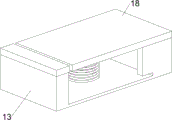
As shown in fig. 5 and 6, the device further comprises a mounting plate 18, a fixed cylinder 19 and a fourth spring 20, the mounting plate 18 is arranged on the rear side of the top of the material box 13, the fixed cylinder 19 is arranged at the bottom of the mounting plate 18, the fourth spring 20 is arranged at the bottom of the mounting plate 18, and the upper portion of the fourth spring 20 is located in the fixed cylinder 19.
When a certain amount of square iron sheets are placed in the material box 13, the square iron sheets extrude the fourth spring 20, so that the fourth spring 20 is compressed, and when the square iron sheets on the lowest side are separated from the material box 13, the square iron sheets can move downwards under the action of the fourth spring 20, thereby avoiding the situation that the square iron sheets cannot fall down due to the rough edge of the square iron sheets clamped in the material box 13.
As shown in fig. 7, the device further comprises a lower pressing rod 21, a second slide rail 22, an installation rod 23, a wedge block 24, a fifth spring 25 and a baffle 26, the second slide rail 22 is symmetrically arranged on the left side of the top of the base 1 in a front-back manner, the installation rod 23 is arranged on the second slide rail 22 in a sliding manner, the wedge block 24 is arranged on the outer side of the installation rod 23, the baffle 26 is arranged on the inner side of the installation rod 23, the baffle 26 is in sliding fit with the second slide rail 22, the fifth spring 25 is connected between the baffle 26 and the inner wall of the second slide rail 22, the lower pressing rod 21 is arranged on the rear side of the installation box 40 and on the left side of the bottom of the first special-shaped.
The mounting box 40 and the first special-shaped rod 6 move downwards to drive the lower pressing rod 21 to move downwards, the lower pressing rod 21 moves downwards to be in contact with the wedge-shaped block 24 and then continues to move, the wedge-shaped blocks 24 on the front side and the rear side are separated from each other, the mounting rods 23 and the baffle plates 26 on the front side and the rear side are driven to be separated from each other, the fifth springs 25 are compressed, then the lower pressing rod 21 moves upwards when the mounting box 40 and the first special-shaped rod 6 move upwards, the lower pressing rod 21 moves upwards gradually without being in contact with the wedge-shaped block 24, the mounting rods 23 and the baffle plates 26 on the front side and the rear side are close to each other and reset under the action of the fifth springs 25, the wedge-shaped blocks 24 on the front side and the rear side are close to and reset, at the moment, the second special-shaped rod 12 pushes the square iron sheet to be between the second mounting blocks 50.
The above description is only an example of the present invention and is not intended to limit the present invention. All equivalents which come within the spirit of the invention are therefore intended to be embraced therein. Details not described herein are well within the skill of those in the art.
Claims (8)
1. The utility model provides an automatic forming machine of circular iron sheet for building industry which characterized in that, including:
the device comprises a base (1), wherein a support (2) is arranged on one side of the top of the base (1), and a groove is formed in one side, close to the support (2), of the top of the base (1);
the cylinder (3) is arranged at the top of the bracket (2), and a U-shaped forming mechanism (4) is connected with a telescopic rod of the cylinder (3);
the round forming mechanism (5) is arranged on one side of the top of the base (1) close to the bracket (2).
2. The building industry circular iron sheet automatic forming machine as claimed in claim 1, wherein the U forming mechanism (4) comprises:
the mounting box (40) is connected with the telescopic rod of the cylinder (3);
the mounting box comprises a first mounting block (41), wherein the first mounting block (41) is arranged in the mounting box (40) in a sliding manner, sliding rods (44) are arranged on two sides of the first mounting block (41), and the sliding rods (44) are in sliding fit with the mounting box (40);
the first spring (43) is connected between the top of the first mounting block (41) and the inner wall of the mounting box (40);
a U-shaped lower pressing device (42), and one part of the first mounting block (41) is provided with the U-shaped lower pressing device (42).
3. The building industry circular iron sheet automatic forming machine as claimed in claim 2, wherein the circular forming mechanism (5) comprises:
two reset rods (51) are arranged on two sides of one side of the base (1) in a sliding manner;
the second mounting blocks (50) are connected between the inner sides of the reset rods (51) on the two sides of the second mounting blocks (50), and the outer ends of the reset rods (51) are provided with fixing blocks (53);
and the second springs (52) are connected between the inner sides of the fixed blocks (53) and the base (1).
4. The building industry circular iron sheet automatic forming machine of claim 3, further comprising:
the special-shaped rack is characterized by comprising a first special-shaped rod (6), wherein the first special-shaped rod (6) is arranged on one side of an installation box (40), a ratchet strip is arranged on one side of the bottom of the first special-shaped rod (6) in a sliding mode, and an elastic piece is connected between one side of the ratchet strip and the first special-shaped rod (6);
the other side of the top of the base (1) is provided with a first sliding rail (7);
the bearing seat (8) is arranged on one side of one side face of the base (1), and a rotating shaft (9) is rotatably arranged on the bearing seat (8);
the ratchet (10) is arranged on one side of the rotating shaft (9), and the ratchet (10) is matched with the ratchet strip;
the other side of the rotating shaft (9) is provided with a gear (11);
a second special-shaped rod (12), wherein one side of the first slide rail (7) is provided with the second special-shaped rod (12) in a sliding way;
a third spring (14) is connected between one side of the second special-shaped rod (12) and the inner wall of the first slide rail (7), and the gear (11) is matched with the second special-shaped rod (12);
a material box (13), the middle of the top of the base (1) is provided with the material box (13), and the second special-shaped rod (12) is matched with the material box (13) in a sliding way.
5. The building industry circular iron sheet automatic forming machine of claim 4, further comprising:
an L-shaped rod (15) is arranged on one side of the bottom of the second special-shaped rod (12);
the discharging push rod (16) is arranged on the base (1) in a sliding mode, and one side of the discharging push rod (16) is connected with the L-shaped rod (15);
a discharge barrel (17), and one side of the bracket (2) is provided with the discharge barrel (17).
6. The automatic building round iron sheet forming machine of claim 5, further comprising:
the mounting plate (18) is arranged on one side of the top of the feed box (13);
the bottom of the mounting plate (18) is provided with a fixed cylinder (19);
the bottom of the mounting plate (18) is provided with a fourth spring (20), and the upper part of the fourth spring (20) is positioned in the fixed cylinder (19).
7. The building industry circular iron sheet automatic forming machine of claim 6, further comprising:
the second sliding rails (22) are symmetrically arranged on one side of the top of the base (1), and mounting rods (23) are arranged on the second sliding rails (22) in a sliding mode;
the wedge block (24) is arranged on one side of the mounting rod (23);
the other side of the mounting rod (23) is provided with a baffle (26), the baffle (26) is in sliding fit with the second slide rail (22), and a fifth spring (25) is connected between the baffle (26) and the inner wall of the second slide rail (22);
the lower pressing rod (21), the other side of the installation box (40) and one side of the first special-shaped rod (6) are respectively provided with the lower pressing rod (21), and the lower pressing rod (21) is matched with the wedge-shaped block (24).
8. The building industry circular iron sheet automatic forming machine of claim 2, characterized in that: the U-shaped presser foot (42) is made of alloy.
Priority Applications (1)
| Application Number | Priority Date | Filing Date | Title |
|---|---|---|---|
| CN202011124557.8A CN112338009A (en) | 2020-10-20 | 2020-10-20 | Automatic forming machine of circular iron sheet for building industry |
Applications Claiming Priority (1)
| Application Number | Priority Date | Filing Date | Title |
|---|---|---|---|
| CN202011124557.8A CN112338009A (en) | 2020-10-20 | 2020-10-20 | Automatic forming machine of circular iron sheet for building industry |
Publications (1)
| Publication Number | Publication Date |
|---|---|
| CN112338009A true CN112338009A (en) | 2021-02-09 |
Family
ID=74358364
Family Applications (1)
| Application Number | Title | Priority Date | Filing Date |
|---|---|---|---|
| CN202011124557.8A Pending CN112338009A (en) | 2020-10-20 | 2020-10-20 | Automatic forming machine of circular iron sheet for building industry |
Country Status (1)
| Country | Link |
|---|---|
| CN (1) | CN112338009A (en) |
Cited By (5)
| Publication number | Priority date | Publication date | Assignee | Title |
|---|---|---|---|---|
| CN113059383A (en) * | 2021-03-16 | 2021-07-02 | 赣州凸凸文化传媒有限公司 | High-end equipment is made with building site equipment steel pipe screw hole slotting device |
| CN113172184A (en) * | 2021-04-07 | 2021-07-27 | 熊美 | Iron ring bending equipment for well lid manufacturing |
| CN113333546A (en) * | 2021-06-02 | 2021-09-03 | 杨爱梅 | Equipment for forming metal ring into fastener |
| CN113352527A (en) * | 2021-05-21 | 2021-09-07 | 陆凤肖 | Be used for socket box compression moulding equipment |
| CN116713401A (en) * | 2023-08-11 | 2023-09-08 | 江苏沙龙机电科技有限公司 | Mechanical timer transmission gear stamping forming device |
Citations (5)
| Publication number | Priority date | Publication date | Assignee | Title |
|---|---|---|---|---|
| CN201720322U (en) * | 2010-04-14 | 2011-01-26 | 无锡市中捷减震器有限公司 | One-step molding mold for round parts |
| US20110048088A1 (en) * | 2006-07-25 | 2011-03-03 | Alois Austaller | Stop mechanism for a bending press |
| CN207288478U (en) * | 2017-09-26 | 2018-05-01 | 芳源企业(上海)有限公司 | A kind of new through hole cylinder pipe crimping pattern tool |
| CN209407131U (en) * | 2019-01-04 | 2019-09-20 | 浙江吉盛机械有限公司 | A kind of sheet metal bending automatic feeding |
| CN210115346U (en) * | 2019-04-11 | 2020-02-28 | 唐山吉辉机械设备有限公司 | Rounding device for panel processing |
-
2020
- 2020-10-20 CN CN202011124557.8A patent/CN112338009A/en active Pending
Patent Citations (5)
| Publication number | Priority date | Publication date | Assignee | Title |
|---|---|---|---|---|
| US20110048088A1 (en) * | 2006-07-25 | 2011-03-03 | Alois Austaller | Stop mechanism for a bending press |
| CN201720322U (en) * | 2010-04-14 | 2011-01-26 | 无锡市中捷减震器有限公司 | One-step molding mold for round parts |
| CN207288478U (en) * | 2017-09-26 | 2018-05-01 | 芳源企业(上海)有限公司 | A kind of new through hole cylinder pipe crimping pattern tool |
| CN209407131U (en) * | 2019-01-04 | 2019-09-20 | 浙江吉盛机械有限公司 | A kind of sheet metal bending automatic feeding |
| CN210115346U (en) * | 2019-04-11 | 2020-02-28 | 唐山吉辉机械设备有限公司 | Rounding device for panel processing |
Cited By (7)
| Publication number | Priority date | Publication date | Assignee | Title |
|---|---|---|---|---|
| CN113059383A (en) * | 2021-03-16 | 2021-07-02 | 赣州凸凸文化传媒有限公司 | High-end equipment is made with building site equipment steel pipe screw hole slotting device |
| CN113172184A (en) * | 2021-04-07 | 2021-07-27 | 熊美 | Iron ring bending equipment for well lid manufacturing |
| CN113352527A (en) * | 2021-05-21 | 2021-09-07 | 陆凤肖 | Be used for socket box compression moulding equipment |
| CN113333546A (en) * | 2021-06-02 | 2021-09-03 | 杨爱梅 | Equipment for forming metal ring into fastener |
| CN113333546B (en) * | 2021-06-02 | 2023-10-10 | 中山市业兴达机械有限公司 | Metal ring shaping and buckling equipment |
| CN116713401A (en) * | 2023-08-11 | 2023-09-08 | 江苏沙龙机电科技有限公司 | Mechanical timer transmission gear stamping forming device |
| CN116713401B (en) * | 2023-08-11 | 2023-10-27 | 江苏沙龙机电科技有限公司 | Mechanical timer transmission gear stamping forming device |
Similar Documents
| Publication | Publication Date | Title |
|---|---|---|
| CN112338009A (en) | Automatic forming machine of circular iron sheet for building industry | |
| CN112246939A (en) | Notch-shaped steel plate stamping equipment for building | |
| CN110586753B (en) | Stamping equipment who possesses garbage collection function | |
| CN113351758B (en) | Automobile part stamping die workpiece | |
| CN112238178A (en) | Forming processing technology for lithium battery connection pole piece | |
| CN218134522U (en) | Automobile oil tank stamping device with material bits clearance is arranged material function | |
| CN216804986U (en) | Device for printing steel seal marks on metal sheets | |
| CN214053273U (en) | Iron sheet stamping equipment for industrial production | |
| CN215697466U (en) | Automatic punch forming device for metal product production | |
| CN115634985A (en) | Intelligent manufacturing process of metal stamping part | |
| CN211101063U (en) | Waste collecting device for punching machine | |
| CN114632881A (en) | Feeding turnover mechanism for stamping die | |
| CN109894221B (en) | Waste license plate shearing mechanism | |
| CN209886461U (en) | Antidetonation connecting piece fixing base forming device | |
| CN112404182A (en) | Stamping device for machining | |
| CN112620445A (en) | Automatic stamping, bending and stacking device | |
| CN112474962A (en) | U type aluminium square tube processingequipment | |
| CN112719028B (en) | Punching device capable of automatically feeding | |
| CN215199391U (en) | Press-forming molding equipment for vehicle part production | |
| CN116727543B (en) | Stamping forming die for sheet metal plate furniture | |
| CN219233664U (en) | Pressing device for preparing automobile tool box | |
| CN113500372B (en) | Semi-automatic special assembly machine for welded pipe | |
| CN219233788U (en) | Blanking device for punching machine table | |
| CN217166187U (en) | Metal mechanical stamping equipment capable of automatically feeding and discharging | |
| CN210475357U (en) | Novel split heads production facility |
Legal Events
| Date | Code | Title | Description |
|---|---|---|---|
| PB01 | Publication | ||
| PB01 | Publication | ||
| SE01 | Entry into force of request for substantive examination | ||
| SE01 | Entry into force of request for substantive examination | ||
| WD01 | Invention patent application deemed withdrawn after publication | ||
| WD01 | Invention patent application deemed withdrawn after publication |
Application publication date: 20210209 |