CN209886461U - Antidetonation connecting piece fixing base forming device - Google Patents
Antidetonation connecting piece fixing base forming device Download PDFInfo
- Publication number
- CN209886461U CN209886461U CN201920550317.0U CN201920550317U CN209886461U CN 209886461 U CN209886461 U CN 209886461U CN 201920550317 U CN201920550317 U CN 201920550317U CN 209886461 U CN209886461 U CN 209886461U
- Authority
- CN
- China
- Prior art keywords
- forming
- push plate
- fixing base
- upper die
- groove
- Prior art date
- Legal status (The legal status is an assumption and is not a legal conclusion. Google has not performed a legal analysis and makes no representation as to the accuracy of the status listed.)
- Active
Links
Images


Landscapes
- Shaping Metal By Deep-Drawing, Or The Like (AREA)
Abstract
The utility model discloses an antidetonation connecting piece fixing base forming device, its characterized in that: including upper die base, setting on the upper die base and can be on the upper die base the last mould that moves, with last mould continuous drive arrangement A, die holder, with the die holder both sides respectively through pivot articulated shaping push pedal, even drive arrangement B is connected to the shaping push pedal, under drive arrangement B's drive, the shaping push pedal can round the pivot is rotated, and die holder and shaping push pedal form the lower mould, shaping push pedal tip is equipped with the arc wall, the utility model discloses still be provided with parts such as guide roll, commentaries on classics roller, compression roller, this forming device mainly used fixing base sheet material's bending shaping can guarantee that the shaping is smooth, and the surface of fixing base can not produce the mar, can play effectual protection to the fixing base, reduces the appearance of substandard product, improves the qualification rate of product.
Description
Technical Field
The utility model relates to a forming device, concretely relates to antidetonation connecting piece fixing base forming device.
Background
The anti-seismic support consists of a reinforced suspender, an anti-seismic connecting piece and an anti-seismic diagonal bracing component; the earthquake-resistant support can greatly reduce the damage of the electromechanical pipelines and equipment in the building to resist the earthquake, prevent secondary disasters, avoid casualties and reduce economic loss.
The fixing base is the part that shock-resistant connecting piece can not be acquireed, wherein shock-resistant connecting piece overall structure is as shown in fig. 1, and the fixing base mainly used is installed on the steel structure, fixing base overall structure is as shown in fig. 2 to make the pivot in the shock-resistant connecting piece install on the fixing base, in traditional manufacturing process, the mounting generally adopts stamping forming, at first carry out the unloading, then punch a hole, carry out the punching press shaping of bending at last, but when the punching press was bent, often can the crackle in the department of bending, the surface quality of fixing base is not good simultaneously, can appear more mar on the surface, even can also appear unqualified product.
SUMMERY OF THE UTILITY MODEL
The utility model aims to overcome among the prior art when bending the fixing base and handling, the mar appears easily in the surface of fixing base, leads to the not good shortcoming of fixing base surface quality, provides an antidetonation connecting piece fixing base forming device, and the shaping of bending of this forming device mainly used fixing base sheet material can guarantee that the shaping is smooth, and the surface of fixing base can not produce the mar, can play effectual protection to the fixing base, reduces the appearance of substandard product, improves the qualification rate of product.
In order to solve the technical problem, the utility model discloses the technical scheme who adopts is:
the utility model provides an antidetonation connecting piece fixing base forming device which characterized in that: the forming device comprises an upper die base, an upper die, a driving device A, a lower die base and a forming push plate, wherein the upper die is arranged on the upper die base and can move on the upper die base, the driving device A is connected with the upper die, the forming push plate is hinged to two sides of the lower die base through a rotating shaft respectively, the forming push plate is connected with a driving device B, the forming push plate can rotate around the rotating shaft under the driving of the driving device B, the lower die base and the forming push plate form a lower die, an arc-shaped groove is formed in the end portion of the forming push plate, a guide roller is arranged on the forming push plate and can rotate on the forming push plate, a rotatable rotating roller is arranged in the arc-shaped groove, a circular groove is formed in the side edge of the upper die, a rotatable compression roller; the lower die base is provided with a groove, a fixed block is arranged in the groove, a cushion block capable of moving in the groove is matched in the groove, support legs are arranged on the cushion block and penetrate through the lower die base, a spring is sleeved on each support leg, one end of the spring is connected with the cushion block, the other end of the spring is connected with the bottom of the groove, and when the spring is in a stretching state, the top surface of the cushion block is higher than the end part of the forming push plate; and a positioning stop block is arranged on the cushion block.
And the end part of one of the forming push plates is connected with a positioning baffle which is L-shaped.
The driving device B is a hydraulic driving device which comprises a hydraulic cylinder, and the movable end of the hydraulic cylinder is hinged with the hinged fixed end of the forming push plate and the lower die base.
Drive arrangement B is for connecting the coupling assembling on shaping push pedal and last mould, coupling assembling includes supporting seat, connecting rod, left sleeve, right sleeve and dowel steel, the extension of die holder is served at the supporting seat installation, the connecting rod is installed on the supporting seat and can be rotated, left and right sleeve suit respectively is at the both ends of connecting rod, and left and right sleeve homoenergetic enough removes on the connecting rod, and left sleeve tip is equipped with the gyro wheel, the support arch is established at the shaping push pedal back, forms the gyro wheel groove between the adjacent support arch, is equipped with the spout on the support arch, the gyro wheel can slide in the gyro wheel groove, be equipped with on the gyro wheel can the guide bar that removes in the spout, dowel steel one end is connected with last mould, and one end is articulated with right sleeve.
The dowel bar is L-shaped.
Compared with the prior art, the utility model discloses following beneficial effect has:
1. the utility model is used for fixing base panel takes shape, when the fixing base panel shaping after to the unloading, can guarantee under the cooperation jointly of the guide roll, commentaries on classics roller, compression roller and backing roll that set up that the fixing base surface does not receive the damage, can effectually guarantee the surface quality of fixing base, reduces the substandard product quantity of fixing base.
2. The utility model discloses change quick punching press into slow punching press, at the in-process that carries out slow punching press, can avoid fixing base panel atress suddenly, this power can not conduct rapidly and open and lead to the punching press position to produce tiny crackle, the utility model discloses can further guarantee the quality of fixing base.
3. The utility model discloses when carrying out the shaping, can carry out accurate location to the fixing base, can guarantee the quality of fixing base.
4. The utility model discloses a coupling assembling that sets up passes power, and when going up the mould and pushing down, the shaping push pedal of setting on the die holder carries out the shaping in step to fixing base panel, and the height that descends in the upper die holder unit interval is proportional to the volume with shaping push pedal unit interval pivoted, can the fashioned quality of effectual assurance fixing base.
Drawings
Fig. 1 is a schematic view of the overall structure of the seismic connector.
Fig. 2 is a schematic view of the overall structure of the molded fixing base.
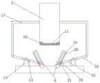
Fig. 3 is a schematic structural diagram of embodiment 1 of the present invention.
Fig. 4 is a schematic view of a connection relationship between the connection assemblies in embodiment 2 of the present invention.
Fig. 5 is a schematic view of a connection relationship of the first connection assembly in embodiment 3 of the present invention.
Reference numerals: the automatic forming device comprises a fixed seat 1, an upper die holder 2, an upper die 3, a driving device A4, a lower die holder 5, a forming push plate 6, a driving device B7, a rotating roller 8, a guide roller 9, a compression roller 10, a supporting roller 11, a positioning baffle 12, a supporting seat 13, a connecting rod 14, a left sleeve 15, a right sleeve 16, a dowel bar 17, a roller 18, a supporting bulge 19, a sliding groove 20, a guide bar 21, a supporting seat A22, a connecting rod A23, a supporting rod A24, a stress rod A25, a groove 26, a fixed block 27, a cushion block 28, a supporting leg 29, a spring 30 and a positioning stop block 31.
Detailed Description
The present invention will be further described with reference to the following examples, which are only some, but not all, of the examples of the present invention. Based on the embodiments in the present invention, other embodiments used by those skilled in the art without creative work belong to the protection scope of the present invention.
Example 1
The embodiment comprises an upper die holder 2, an upper die 3 which is arranged on the upper die holder 2 and can move on the upper die holder 2, a driving device A4 which is connected with the upper die 3, a lower die holder 5, and a forming push plate 6 which is respectively hinged with two sides of the lower die holder 5 through rotating shafts, wherein the forming push plate 6 is connected with a driving device B7, under the drive of a driving device B7, the molding push plate 6 can rotate around the rotating shaft, the lower die base 5 and the molding push plate 6 form a lower die, the end part of the molding push plate 6 is provided with an arc-shaped groove, a rotary roller 8 which can rotate is arranged in the arc-shaped groove, a guide roller 9 is arranged on the forming push plate 6, the guide roller 9 can rotate on the forming push plate 6, the side edge of the upper die 3 is provided with a circular groove, be equipped with in the circular slot and can rotate compression roller 10, the lower mould bottom is located and is equipped with a plurality of backing rolls 11 between compression roller 10, backing roll 11 can rotate.
Note that the surfaces of the rotating roller 8 and the guide roller 9 are on the same plane, and the surfaces of the press roller 10 and the support roller 11 are also on the same plane.
Thus, when the fixed seat 1 is bent and formed, the blanked fixed seat 1 plate is only required to be placed on a lower die formed by the lower die base 5 and the forming push plate 6, that is, the fixed seat 1 is placed on the rotating roller 8, the driving device a4 drives the upper die 3 to descend, so that the upper surface and the lower surface of the fixed seat 1 are respectively contacted with the pressing roller 10 and the rotating roller 8, the upper die 3 continues to press down to bend the fixed seat 1, at the moment, the forming push plate 6 can rotate around the rotating shaft to extrude the side surface of the fixed seat 1 under the driving of the driving device B7, at the moment, the fixed seat 1 can be slowly formed under the action of the upper die 3 and the forming push plate 6, during the forming process, as the upper die 3 presses down the fixed seat 1, the forming push plate 6 supports and simultaneously extrudes the fixed seat 1, the guide roller 9 can be rotated by the friction force on the surface of, meanwhile, the compression roller 10 will also rotate, and the rotary roller 8 will also rotate in the process of continuous descending of the lower die, so that the surface of the fixed seat 1 is prevented from being scratched, and the fixed seat 1 is supported; the supporting roller 11 mainly plays a supporting role, so that the bottom surface of the fixing seat 1 is prevented from deforming, and meanwhile, the forming of the side edge of the fixing seat 1 is ensured; in the shaping of reality, change the rapid prototyping in the tradition into low-speed shaping, through the lower mould, shaping push pedal 6, guide roll 9, the cooperation jointly of compression roller 10 etc, become rolling friction with sliding friction when the shaping, can effectually avoid the upper and lower surface of fixing base 1, the lower surface is impaired, can effectual improvement fixing base 1's whole quality, and simultaneously, at the fashioned in-process, fixing base 1 will slowly take place deformation, last shaping, can make fixing base 1 slowly atress like this, it conducts the dispersion to have longer time with the atress, and then guarantee the quality of fixing base 1 when the shaping, avoid fixing base 1 department of bending to produce tiny crackle, and further guarantee the quality of fixing base 1, improve fixing base 1's qualification rate.
Further preferably, a positioning baffle plate 12 is connected to the end of one of the forming push plates 6, and the positioning baffle plate 12 is L-shaped.
Like this, can carry out accurate location with fixing base 1 panel after the unloading, the shaping of fixing base 1 of being convenient for to improve fixing base 1's quality.
It should be noted that there may be two positioning baffles 12, and each positioning baffle is disposed at an end of the forming push plate 6.
The driving device B7 is a hydraulic driving device which comprises a hydraulic cylinder, and the movable end of the hydraulic cylinder is hinged with the hinged fixed end of the molding push plate 6 and the lower die holder 5.
Wherein the driving device a4 is a hydraulic driving device.
Like this, drive through hydraulic means and go up mould 3 and shaping push pedal 6 for go up mould 3 and shaping push pedal 6 more steady in the removal, reach fixing base 1 fashioned purpose at a slow speed simultaneously, guarantee fixing base 1's quality.
Example 2
The embodiment is substantially the same as embodiment 1, and the difference is that the driving device B7 is a connecting assembly connected to the forming push plate 6 and the upper die 3, the connecting assembly includes a supporting seat 13, a connecting rod 14, a left sleeve 15, a right sleeve 16 and a transmission rod 17, the supporting seat 13 is installed at the extended end of the lower die base 5, the connecting rod 14 is installed on the supporting seat 13 and can rotate, the left and right sleeves are respectively sleeved at two ends of the connecting rod 14, the left and right sleeves can move on the connecting rod 14, the end of the left sleeve 15 is provided with a roller 18, the back of the forming push plate 6 is provided with a supporting protrusion 19, a roller groove is formed between adjacent supporting protrusions 19, the supporting protrusion 19 is provided with a sliding groove 20, the roller 18 can slide in the roller groove, the roller 18 is provided with a guide rod 21 capable of moving in the sliding groove 20, one end of the transmission rod 17 is connected to, one end is hinged to the right sleeve 16.
The guide bar 21 is a rotating shaft for fixing the roller 18 to the left sleeve 15.
Thus, when the fixed seat 1 is formed, the forming push plate 6 can move synchronously when the upper die descends, the descending height of the upper die in unit time is in proportion to the rotating amount of the forming push plate 6 in unit time, thus ensuring that the fixed seat 1 can form in place when the upper die 3 descends in place, in practice, as the left sleeve 15 and the right sleeve 16 are sleeved on the connecting rod 14 and can move on the connecting rod 14, and the connecting rod 14 is installed on the supporting seat 13 and can rotate, thus forming a lever system, when the upper die 3 descends, under the action of the force transmission rod 17, the right sleeve 16 can move on the connecting rod 14, and the right end of the connecting rod 14 descends, and the left end upwarps, so that the roller 18 on the left sleeve 15 moves in the roller and the groove, so that the guide rod 21 arranged on the roller 18 can move in the sliding groove 20, and the forming push plate 6 rotates, and (4) performing auxiliary forming on the fixed seat 1.
Wherein, dowel bar 17 is L-shaped.
It should be noted that, in order to better drive the movement of the forming push plate 6, the connecting assembly should be provided in plurality.
Example 3
The embodiment is substantially the same as embodiment 1, except that the driving device B7 is a first connecting assembly connected to the forming push plate 6 and the lower die, the first connecting assembly includes a supporting seat a22, a connecting rod a23, a supporting rod a24 and a stressed rod a25, the connecting rod a23 is mounted on the supporting seat a22 through a rotating shaft, the connecting rod a23 can rotate around the rotating shaft, one end of the supporting rod a24 is hinged to the connecting rod a23, the other end is hinged to the forming push plate 6, the stressed rod a25 is L-shaped, one end of the stressed rod a25 is fixedly connected to the upper die 3, and the other end of the stressed rod a23 is hinged to the connecting rod a.
Set up like this, can so that when going up mould 3 and removing, can drive shaping push pedal 6 through comparatively simple structure and rotate, the structure is simpler, avoids bringing more assembly error because of the part is too much, simultaneously, realizes that shaping push pedal 6 assists the shaping purpose to fixing base 1.
Example 4
This embodiment is further optimized on the basis of embodiment 1, and in this embodiment, is equipped with recess 26 on the lower die holder 5, install fixed block 27 in the recess 26, recess 26 fit in has can be in recess 26 removal cushion 28, be equipped with stabilizer blade 29 on the cushion 28, stabilizer blade 29 passes lower die holder 5, the cover is equipped with spring 30 on the stabilizer blade 29, this spring 30 one end is connected with cushion 28, the other end with recess 26 bottom is connected, when spring 30 was in the state of stretching out, the top surface was higher than the tip of shaping push pedal 6 on the cushion 28.
Thus, when the upper die 3 is pressed downwards, the purpose of buffering the fixing seat 1 can be achieved until the cushion block 28 is pressed on the fixing block 27, so that the lower dies are formed on the surfaces of the forming push plate 6 and the cushion block 28, the forming push plate 6 can be attached to the side wall of the cushion block 28 after rotating, smooth forming of the fixing seat 1 is guaranteed, after the forming of the fixing seat 1 is finished, the cushion block 28 ejects the fixing seat 1 under the action of the spring 30, the fixing seat 1 is higher than the forming push plate 6, and workers can take out workpieces more conveniently; meanwhile, after the forming push plate 6 is attached to the cushion block 28, the transition arc of the fixed seat 1 at the bending position is smaller, and the fixed part 1 is better in shape and quality; more importantly, under the effect of spring 30, the last top surface of cushion 28 will be higher than the tip of shaping push pedal 6, places fixing base 1 panel like this on cushion 28, and cushion 28 can play the effect of supporting, and under the effect of locating baffle 12, realizes the location to fixing base 1.
Preferably, a positioning stop 31 is arranged on the cushion block 28.
Like this, can realize the accurate positioning to fixing base 1 through location dog 31 and the positioning baffle 12 that set up, when the location for fixing base 1's terminal surface contacts with location dog 31, and fixing base 1's side contacts with positioning baffle 12, thereby realizes the accurate location to fixing base 1, guarantees the quality of shaping back fixing base 1.
Claims (5)
1. The utility model provides an antidetonation connecting piece fixing base forming device which characterized in that: the forming device comprises an upper die base, an upper die, a driving device A, a lower die base and a forming push plate, wherein the upper die is arranged on the upper die base and can move on the upper die base, the driving device A is connected with the upper die, the forming push plate is hinged to two sides of the lower die base through a rotating shaft respectively, the forming push plate is connected with a driving device B, the forming push plate can rotate around the rotating shaft under the driving of the driving device B, the lower die base and the forming push plate form a lower die, an arc-shaped groove is formed in the end portion of the forming push plate, a rotatable rotating roller is arranged in the arc-shaped groove, a guide roller is arranged on the forming push plate and can rotate on the forming push plate, a circular groove is formed in the side edge of the upper die, a rotatable compression roller; the improved die holder is characterized in that a groove is formed in the lower die holder, a fixing block is installed in the groove, a cushion block capable of moving in the groove is matched in the groove, supporting legs are arranged on the cushion block and penetrate through the lower die holder, a spring is sleeved on the supporting legs, one end of the spring is connected with the cushion block, the other end of the spring is connected with the bottom of the groove, the top surface of the spring is higher than the end portion of the forming push plate when the spring is in an unfolding state, and a positioning stop block is arranged on the cushion block.
2. The device for forming the fixed seat of the anti-seismic connecting piece as claimed in claim 1, wherein: and the end part of one of the forming push plates is connected with a positioning baffle which is L-shaped.
3. The device for forming the fixed seat of the anti-seismic connecting piece as claimed in claim 1, wherein: the driving device B is a hydraulic driving device which comprises a hydraulic cylinder, the movable end of the hydraulic cylinder is hinged with the forming push plate, and the fixed end of the hydraulic cylinder is hinged with the lower die holder.
4. The device for forming the fixed seat of the anti-seismic connecting piece as claimed in claim 1, wherein: drive arrangement B is for connecting the coupling assembling on shaping push pedal and last mould, coupling assembling includes supporting seat, connecting rod, left sleeve, right sleeve and dowel steel, the extension of die holder is served at the supporting seat installation, the connecting rod is installed on the supporting seat and can be rotated, left and right sleeve suit respectively is at the both ends of connecting rod, and left and right sleeve homoenergetic enough removes on the connecting rod, and left sleeve tip is equipped with the gyro wheel, the support arch is established at the shaping push pedal back, forms the gyro wheel groove between the adjacent support arch, is equipped with the spout on the support arch, the gyro wheel can slide in the gyro wheel groove, be equipped with on the gyro wheel can the guide bar that removes in the spout, dowel steel one end is connected with last mould, and one end is articulated with right sleeve.
5. The device of claim 4, wherein the device comprises: the dowel bar is L-shaped.
Priority Applications (1)
| Application Number | Priority Date | Filing Date | Title |
|---|---|---|---|
| CN201920550317.0U CN209886461U (en) | 2019-04-22 | 2019-04-22 | Antidetonation connecting piece fixing base forming device |
Applications Claiming Priority (1)
| Application Number | Priority Date | Filing Date | Title |
|---|---|---|---|
| CN201920550317.0U CN209886461U (en) | 2019-04-22 | 2019-04-22 | Antidetonation connecting piece fixing base forming device |
Publications (1)
| Publication Number | Publication Date |
|---|---|
| CN209886461U true CN209886461U (en) | 2020-01-03 |
Family
ID=68999589
Family Applications (1)
| Application Number | Title | Priority Date | Filing Date |
|---|---|---|---|
| CN201920550317.0U Active CN209886461U (en) | 2019-04-22 | 2019-04-22 | Antidetonation connecting piece fixing base forming device |
Country Status (1)
| Country | Link |
|---|---|
| CN (1) | CN209886461U (en) |
Cited By (3)
| Publication number | Priority date | Publication date | Assignee | Title |
|---|---|---|---|---|
| CN116944317A (en) * | 2023-09-18 | 2023-10-27 | 兴化市富邦机械有限公司 | Hardware stamping device |
| CN118403947A (en) * | 2024-07-02 | 2024-07-30 | 杭州萧山恒发线路设备有限公司 | Compression molding device and molding method for totally-enclosed corrosion-resistant anti-interference cable bridge |
| CN118417379A (en) * | 2024-07-02 | 2024-08-02 | 安徽常力达电气有限公司 | Bending equipment for processing box-type substation shell |
-
2019
- 2019-04-22 CN CN201920550317.0U patent/CN209886461U/en active Active
Cited By (6)
| Publication number | Priority date | Publication date | Assignee | Title |
|---|---|---|---|---|
| CN116944317A (en) * | 2023-09-18 | 2023-10-27 | 兴化市富邦机械有限公司 | Hardware stamping device |
| CN116944317B (en) * | 2023-09-18 | 2023-12-26 | 兴化市富邦机械有限公司 | Hardware stamping device |
| CN118403947A (en) * | 2024-07-02 | 2024-07-30 | 杭州萧山恒发线路设备有限公司 | Compression molding device and molding method for totally-enclosed corrosion-resistant anti-interference cable bridge |
| CN118417379A (en) * | 2024-07-02 | 2024-08-02 | 安徽常力达电气有限公司 | Bending equipment for processing box-type substation shell |
| CN118417379B (en) * | 2024-07-02 | 2024-09-06 | 安徽常力达电气有限公司 | Bending equipment for processing box-type substation shell |
| CN118403947B (en) * | 2024-07-02 | 2024-09-13 | 杭州萧山恒发线路设备有限公司 | Compression molding device and molding method for totally-enclosed corrosion-resistant anti-interference cable bridge |
Similar Documents
| Publication | Publication Date | Title |
|---|---|---|
| CN209886461U (en) | Antidetonation connecting piece fixing base forming device | |
| CN202447512U (en) | Bending die with stable dimensions | |
| CN113857296A (en) | Sheet metal flattening straightener | |
| CN204108121U (en) | A kind of panel beating can't harm apparatus for bending | |
| CN114211624A (en) | Adjusting device for punching of constructional engineering plates | |
| CN218168299U (en) | Angle-adjustable bending machine for sheet metal machining | |
| CN209886496U (en) | Antidetonation connecting piece fixing base forming die | |
| CN217665572U (en) | Rotary protection bending die structure | |
| CN114632881A (en) | Feeding turnover mechanism for stamping die | |
| CN210788874U (en) | Left rear crossbeam forming die | |
| CN115224567A (en) | Electric elements terminal stamping device | |
| CN214133434U (en) | Stationery is sheet metal component bending device for manufacturing | |
| CN214022849U (en) | Steel plate stamping and welding equipment | |
| CN210412355U (en) | Workbench positioning device of press machine | |
| CN213317350U (en) | Cable buckle stamping forming device | |
| CN205519195U (en) | Set up elevator link plate stamping die of synchronous ware | |
| CN218224144U (en) | Sheet metal shaping device that bends | |
| CN214133494U (en) | Stamping structure capable of quickly adjusting plate position | |
| CN219324641U (en) | Stamping die that no trace was bent | |
| CN215902514U (en) | Bar traceless forming stamping die | |
| CN218925782U (en) | Sheet metal stamping device | |
| CN111215527A (en) | U-shaped bolt forming die | |
| CN215785735U (en) | Stretcher for silver pot production process | |
| CN219664914U (en) | Solar frame riveting point die | |
| CN214290153U (en) | Rolling type bending structure |
Legal Events
| Date | Code | Title | Description |
|---|---|---|---|
| GR01 | Patent grant | ||
| GR01 | Patent grant |