CN112334645B - Internal combustion engine - Google Patents
Internal combustion engine Download PDFInfo
- Publication number
- CN112334645B CN112334645B CN201880095166.2A CN201880095166A CN112334645B CN 112334645 B CN112334645 B CN 112334645B CN 201880095166 A CN201880095166 A CN 201880095166A CN 112334645 B CN112334645 B CN 112334645B
- Authority
- CN
- China
- Prior art keywords
- exhaust
- egr
- intake
- pressure
- internal combustion
- Prior art date
- Legal status (The legal status is an assumption and is not a legal conclusion. Google has not performed a legal analysis and makes no representation as to the accuracy of the status listed.)
- Active
Links
Images


Classifications
-
- F—MECHANICAL ENGINEERING; LIGHTING; HEATING; WEAPONS; BLASTING
- F02—COMBUSTION ENGINES; HOT-GAS OR COMBUSTION-PRODUCT ENGINE PLANTS
- F02D—CONTROLLING COMBUSTION ENGINES
- F02D41/00—Electrical control of supply of combustible mixture or its constituents
- F02D41/0002—Controlling intake air
- F02D41/0007—Controlling intake air for control of turbo-charged or super-charged engines
-
- F—MECHANICAL ENGINEERING; LIGHTING; HEATING; WEAPONS; BLASTING
- F02—COMBUSTION ENGINES; HOT-GAS OR COMBUSTION-PRODUCT ENGINE PLANTS
- F02B—INTERNAL-COMBUSTION PISTON ENGINES; COMBUSTION ENGINES IN GENERAL
- F02B37/00—Engines characterised by provision of pumps driven at least for part of the time by exhaust
- F02B37/12—Control of the pumps
- F02B37/20—Control of the pumps by increasing exhaust energy, e.g. using combustion chamber by after-burning
-
- F—MECHANICAL ENGINEERING; LIGHTING; HEATING; WEAPONS; BLASTING
- F02—COMBUSTION ENGINES; HOT-GAS OR COMBUSTION-PRODUCT ENGINE PLANTS
- F02B—INTERNAL-COMBUSTION PISTON ENGINES; COMBUSTION ENGINES IN GENERAL
- F02B37/00—Engines characterised by provision of pumps driven at least for part of the time by exhaust
- F02B37/12—Control of the pumps
- F02B37/24—Control of the pumps by using pumps or turbines with adjustable guide vanes
-
- F—MECHANICAL ENGINEERING; LIGHTING; HEATING; WEAPONS; BLASTING
- F02—COMBUSTION ENGINES; HOT-GAS OR COMBUSTION-PRODUCT ENGINE PLANTS
- F02B—INTERNAL-COMBUSTION PISTON ENGINES; COMBUSTION ENGINES IN GENERAL
- F02B39/00—Component parts, details, or accessories relating to, driven charging or scavenging pumps, not provided for in groups F02B33/00 - F02B37/00
- F02B39/02—Drives of pumps; Varying pump drive gear ratio
- F02B39/04—Mechanical drives; Variable-gear-ratio drives
-
- F—MECHANICAL ENGINEERING; LIGHTING; HEATING; WEAPONS; BLASTING
- F02—COMBUSTION ENGINES; HOT-GAS OR COMBUSTION-PRODUCT ENGINE PLANTS
- F02B—INTERNAL-COMBUSTION PISTON ENGINES; COMBUSTION ENGINES IN GENERAL
- F02B39/00—Component parts, details, or accessories relating to, driven charging or scavenging pumps, not provided for in groups F02B33/00 - F02B37/00
- F02B39/02—Drives of pumps; Varying pump drive gear ratio
- F02B39/08—Non-mechanical drives, e.g. fluid drives having variable gear ratio
- F02B39/10—Non-mechanical drives, e.g. fluid drives having variable gear ratio electric
-
- F—MECHANICAL ENGINEERING; LIGHTING; HEATING; WEAPONS; BLASTING
- F02—COMBUSTION ENGINES; HOT-GAS OR COMBUSTION-PRODUCT ENGINE PLANTS
- F02B—INTERNAL-COMBUSTION PISTON ENGINES; COMBUSTION ENGINES IN GENERAL
- F02B67/00—Engines characterised by the arrangement of auxiliary apparatus not being otherwise provided for, e.g. the apparatus having different functions; Driving auxiliary apparatus from engines, not otherwise provided for
- F02B67/04—Engines characterised by the arrangement of auxiliary apparatus not being otherwise provided for, e.g. the apparatus having different functions; Driving auxiliary apparatus from engines, not otherwise provided for of mechanically-driven auxiliary apparatus
- F02B67/06—Engines characterised by the arrangement of auxiliary apparatus not being otherwise provided for, e.g. the apparatus having different functions; Driving auxiliary apparatus from engines, not otherwise provided for of mechanically-driven auxiliary apparatus driven by means of chains, belts, or like endless members
-
- F—MECHANICAL ENGINEERING; LIGHTING; HEATING; WEAPONS; BLASTING
- F02—COMBUSTION ENGINES; HOT-GAS OR COMBUSTION-PRODUCT ENGINE PLANTS
- F02D—CONTROLLING COMBUSTION ENGINES
- F02D13/00—Controlling the engine output power by varying inlet or exhaust valve operating characteristics, e.g. timing
- F02D13/02—Controlling the engine output power by varying inlet or exhaust valve operating characteristics, e.g. timing during engine operation
- F02D13/0223—Variable control of the intake valves only
- F02D13/0234—Variable control of the intake valves only changing the valve timing only
-
- F—MECHANICAL ENGINEERING; LIGHTING; HEATING; WEAPONS; BLASTING
- F02—COMBUSTION ENGINES; HOT-GAS OR COMBUSTION-PRODUCT ENGINE PLANTS
- F02D—CONTROLLING COMBUSTION ENGINES
- F02D13/00—Controlling the engine output power by varying inlet or exhaust valve operating characteristics, e.g. timing
- F02D13/02—Controlling the engine output power by varying inlet or exhaust valve operating characteristics, e.g. timing during engine operation
- F02D13/0269—Controlling the valves to perform a Miller-Atkinson cycle
-
- F—MECHANICAL ENGINEERING; LIGHTING; HEATING; WEAPONS; BLASTING
- F02—COMBUSTION ENGINES; HOT-GAS OR COMBUSTION-PRODUCT ENGINE PLANTS
- F02D—CONTROLLING COMBUSTION ENGINES
- F02D41/00—Electrical control of supply of combustible mixture or its constituents
- F02D41/0025—Controlling engines characterised by use of non-liquid fuels, pluralities of fuels, or non-fuel substances added to the combustible mixtures
- F02D41/0047—Controlling exhaust gas recirculation [EGR]
- F02D41/0077—Control of the EGR valve or actuator, e.g. duty cycle, closed loop control of position
-
- F—MECHANICAL ENGINEERING; LIGHTING; HEATING; WEAPONS; BLASTING
- F02—COMBUSTION ENGINES; HOT-GAS OR COMBUSTION-PRODUCT ENGINE PLANTS
- F02D—CONTROLLING COMBUSTION ENGINES
- F02D41/00—Electrical control of supply of combustible mixture or its constituents
- F02D41/02—Circuit arrangements for generating control signals
- F02D41/14—Introducing closed-loop corrections
- F02D41/1438—Introducing closed-loop corrections using means for determining characteristics of the combustion gases; Sensors therefor
- F02D41/1444—Introducing closed-loop corrections using means for determining characteristics of the combustion gases; Sensors therefor characterised by the characteristics of the combustion gases
- F02D41/1448—Introducing closed-loop corrections using means for determining characteristics of the combustion gases; Sensors therefor characterised by the characteristics of the combustion gases the characteristics being an exhaust gas pressure
-
- F—MECHANICAL ENGINEERING; LIGHTING; HEATING; WEAPONS; BLASTING
- F02—COMBUSTION ENGINES; HOT-GAS OR COMBUSTION-PRODUCT ENGINE PLANTS
- F02D—CONTROLLING COMBUSTION ENGINES
- F02D41/00—Electrical control of supply of combustible mixture or its constituents
- F02D41/24—Electrical control of supply of combustible mixture or its constituents characterised by the use of digital means
- F02D41/26—Electrical control of supply of combustible mixture or its constituents characterised by the use of digital means using computer, e.g. microprocessor
-
- F—MECHANICAL ENGINEERING; LIGHTING; HEATING; WEAPONS; BLASTING
- F02—COMBUSTION ENGINES; HOT-GAS OR COMBUSTION-PRODUCT ENGINE PLANTS
- F02M—SUPPLYING COMBUSTION ENGINES IN GENERAL WITH COMBUSTIBLE MIXTURES OR CONSTITUENTS THEREOF
- F02M26/00—Engine-pertinent apparatus for adding exhaust gases to combustion-air, main fuel or fuel-air mixture, e.g. by exhaust gas recirculation [EGR] systems
- F02M26/02—EGR systems specially adapted for supercharged engines
- F02M26/04—EGR systems specially adapted for supercharged engines with a single turbocharger
- F02M26/05—High pressure loops, i.e. wherein recirculated exhaust gas is taken out from the exhaust system upstream of the turbine and reintroduced into the intake system downstream of the compressor
-
- F—MECHANICAL ENGINEERING; LIGHTING; HEATING; WEAPONS; BLASTING
- F02—COMBUSTION ENGINES; HOT-GAS OR COMBUSTION-PRODUCT ENGINE PLANTS
- F02M—SUPPLYING COMBUSTION ENGINES IN GENERAL WITH COMBUSTIBLE MIXTURES OR CONSTITUENTS THEREOF
- F02M26/00—Engine-pertinent apparatus for adding exhaust gases to combustion-air, main fuel or fuel-air mixture, e.g. by exhaust gas recirculation [EGR] systems
- F02M26/13—Arrangement or layout of EGR passages, e.g. in relation to specific engine parts or for incorporation of accessories
- F02M26/14—Arrangement or layout of EGR passages, e.g. in relation to specific engine parts or for incorporation of accessories in relation to the exhaust system
- F02M26/16—Arrangement or layout of EGR passages, e.g. in relation to specific engine parts or for incorporation of accessories in relation to the exhaust system with EGR valves located at or near the connection to the exhaust system
-
- F—MECHANICAL ENGINEERING; LIGHTING; HEATING; WEAPONS; BLASTING
- F02—COMBUSTION ENGINES; HOT-GAS OR COMBUSTION-PRODUCT ENGINE PLANTS
- F02M—SUPPLYING COMBUSTION ENGINES IN GENERAL WITH COMBUSTIBLE MIXTURES OR CONSTITUENTS THEREOF
- F02M26/00—Engine-pertinent apparatus for adding exhaust gases to combustion-air, main fuel or fuel-air mixture, e.g. by exhaust gas recirculation [EGR] systems
- F02M26/13—Arrangement or layout of EGR passages, e.g. in relation to specific engine parts or for incorporation of accessories
- F02M26/22—Arrangement or layout of EGR passages, e.g. in relation to specific engine parts or for incorporation of accessories with coolers in the recirculation passage
-
- F—MECHANICAL ENGINEERING; LIGHTING; HEATING; WEAPONS; BLASTING
- F02—COMBUSTION ENGINES; HOT-GAS OR COMBUSTION-PRODUCT ENGINE PLANTS
- F02M—SUPPLYING COMBUSTION ENGINES IN GENERAL WITH COMBUSTIBLE MIXTURES OR CONSTITUENTS THEREOF
- F02M26/00—Engine-pertinent apparatus for adding exhaust gases to combustion-air, main fuel or fuel-air mixture, e.g. by exhaust gas recirculation [EGR] systems
- F02M26/13—Arrangement or layout of EGR passages, e.g. in relation to specific engine parts or for incorporation of accessories
- F02M26/34—Arrangement or layout of EGR passages, e.g. in relation to specific engine parts or for incorporation of accessories with compressors, turbines or the like in the recirculation passage
-
- F—MECHANICAL ENGINEERING; LIGHTING; HEATING; WEAPONS; BLASTING
- F02—COMBUSTION ENGINES; HOT-GAS OR COMBUSTION-PRODUCT ENGINE PLANTS
- F02M—SUPPLYING COMBUSTION ENGINES IN GENERAL WITH COMBUSTIBLE MIXTURES OR CONSTITUENTS THEREOF
- F02M35/00—Combustion-air cleaners, air intakes, intake silencers, or induction systems specially adapted for, or arranged on, internal-combustion engines
- F02M35/10—Air intakes; Induction systems
- F02M35/10209—Fluid connections to the air intake system; their arrangement of pipes, valves or the like
- F02M35/10222—Exhaust gas recirculation [EGR]; Positive crankcase ventilation [PCV]; Additional air admission, lubricant or fuel vapour admission
-
- F—MECHANICAL ENGINEERING; LIGHTING; HEATING; WEAPONS; BLASTING
- F02—COMBUSTION ENGINES; HOT-GAS OR COMBUSTION-PRODUCT ENGINE PLANTS
- F02B—INTERNAL-COMBUSTION PISTON ENGINES; COMBUSTION ENGINES IN GENERAL
- F02B2275/00—Other engines, components or details, not provided for in other groups of this subclass
- F02B2275/32—Miller cycle
-
- F—MECHANICAL ENGINEERING; LIGHTING; HEATING; WEAPONS; BLASTING
- F02—COMBUSTION ENGINES; HOT-GAS OR COMBUSTION-PRODUCT ENGINE PLANTS
- F02D—CONTROLLING COMBUSTION ENGINES
- F02D2200/00—Input parameters for engine control
- F02D2200/02—Input parameters for engine control the parameters being related to the engine
- F02D2200/04—Engine intake system parameters
- F02D2200/0406—Intake manifold pressure
-
- F—MECHANICAL ENGINEERING; LIGHTING; HEATING; WEAPONS; BLASTING
- F02—COMBUSTION ENGINES; HOT-GAS OR COMBUSTION-PRODUCT ENGINE PLANTS
- F02G—HOT GAS OR COMBUSTION-PRODUCT POSITIVE-DISPLACEMENT ENGINE PLANTS; USE OF WASTE HEAT OF COMBUSTION ENGINES; NOT OTHERWISE PROVIDED FOR
- F02G5/00—Profiting from waste heat of combustion engines, not otherwise provided for
- F02G5/02—Profiting from waste heat of exhaust gases
-
- Y—GENERAL TAGGING OF NEW TECHNOLOGICAL DEVELOPMENTS; GENERAL TAGGING OF CROSS-SECTIONAL TECHNOLOGIES SPANNING OVER SEVERAL SECTIONS OF THE IPC; TECHNICAL SUBJECTS COVERED BY FORMER USPC CROSS-REFERENCE ART COLLECTIONS [XRACs] AND DIGESTS
- Y02—TECHNOLOGIES OR APPLICATIONS FOR MITIGATION OR ADAPTATION AGAINST CLIMATE CHANGE
- Y02T—CLIMATE CHANGE MITIGATION TECHNOLOGIES RELATED TO TRANSPORTATION
- Y02T10/00—Road transport of goods or passengers
- Y02T10/10—Internal combustion engine [ICE] based vehicles
- Y02T10/12—Improving ICE efficiencies
Abstract
The invention relates to an internal combustion engine comprising: a crankshaft; one or more cylinders including a cylinder head, a piston, a combustion chamber; one or more intake valves; one or more exhaust valves; an intake system configured to deliver intake air to the engine; an exhaust system configured to carry exhaust gases away from the engine; a boost system connected to the intake system; and an Exhaust Gas Recirculation (EGR) system arranged to deliver exhaust gas branched from the exhaust system to the intake system via an EGR conduit, wherein the internal combustion engine comprises valve actuation means configured to allow delayed or advanced closing of the intake valve in accordance with delayed or advanced miller-type valve timing, and wherein the EGR system comprises gas delivery means configured to deliver exhaust gas through the EGR conduit in an operating mode in which pressure in the intake system exceeds pressure in the exhaust system. In addition, a method of increasing the efficiency of an internal combustion engine is described.
Description
Technical Field
The present invention relates to an internal combustion engine and a method of increasing the efficiency of an internal combustion engine.
The present invention can be applied to various combustion engines. However, the invention is particularly advantageous when applied to engines configured for heavy-duty applications (such as trucks, buses, construction equipment), marine applications, and stationary applications.
Although the invention will be described below in relation to an application in a truck, the invention is not in any way limited to this particular application.
Background
Heavy duty internal combustion engines are well known in the art.
To minimize fuel consumption, recent internal combustion engines may be equipped with advanced turbine systems configured to recover energy in the exhaust stream. Advanced turbine systems may include a turbocharger in the first stage, which is disposed in the exhaust stream downstream of the engine. The turbocharger is configured to convert energy from the exhaust gas into a pressure increase of the intake air. In a second paragraph, the advanced turbine system may include a turbo complex unit downstream of the turbocharger, the turbo complex unit being configured to convert at least a portion of the remaining energy in the exhaust gas into rotational motion of the shaft. The rotational motion of the shaft is transferred as a torque contribution to the crankshaft of the engine.
As an example, other known turbine systems include two turbochargers arranged in series such that the intake air is compressed in two stages, including an initial compression by one of the turbochargers and a final compression by the second turbocharger.
The use of advanced turbine systems has proven to be a significant advantage; particularly in terms of fuel efficiency.
Exhaust gas recirculation systems (EGR) have been widely used for many years, in order to reduce in particular the emissions of nitrogen oxides (NOx), the formation of which is highly dependent on the temperature in the combustion chamber. NOx is produced in a relatively narrow range of high cylinder temperatures and pressures. The recirculation of exhaust gases actually dilutes the oxygen level in the intake air by supplying inert gases to the combustion; thereby acting as an absorber of combustion heat to reduce the cylinder temperature.
In a high-pressure external EGR system (sometimes referred to as a short-range EGR system), exhaust gas is branched from the exhaust gas flow upstream of any turbine disposed in the exhaust system, while in a low-pressure external EGR system (sometimes referred to as a long-range EGR system), exhaust gas is branched from the exhaust gas flow downstream of any turbine disposed in the exhaust system; sometimes also downstream of any catalytic converter and/or any exhaust gas particulate filter. Internal EGR systems have also been proposed in which a portion of the exhaust gas remains in the cylinder.
In particular, but not exclusively, during the transition portion of an engine operating cycle, the flow rate of exhaust gas recirculation may not be sufficient to provide the above-described effect because, on engines provided with advanced turbine systems and incorporating EGR systems, the pressure differential between the exhaust system and the charge air intake system may not be sufficient to promote the EGR flow rate required to control engine emissions (NOx).
One approach to dealing with EGR for engines with intake side pressures higher than exhaust side pressures is to utilize a technique known as VGT (variable geometry turbine), in which the flow area of the turbine is reduced until the back pressure in the exhaust manifold is sufficient to establish EGR drive. This reduces turbine efficiency, but the technique is functional because it can be adjusted to different engine operating modes. Another way is to increase the back pressure by arranging another exhaust turbine downstream of the turbo charger turbine, allowing some energy to be recovered via this other turbine. This is commonly referred to as turbo compounding. It has further been proposed to arrange a pump/compressor in an EGR system to deliver gas from the exhaust side to the intake side. However, this design is rare on commercial engines, which may be due to durability issues. Low pressure EGR systems have also been proposed for engines having higher pressures on the intake side than on the exhaust side. A general disadvantage of low pressure EGR is that it adds more weight and cost and requires more space than high pressure EGR. In general, a major concern with this type of engine is the development of various VGT and turbo compound designs.
Another method of improving engine efficiency is to use early or late closing of the intake valve so that the intake valve closes during the intake stroke before the piston reaches its Bottom Dead Center (BDC) in some cases, to allow a smaller amount of air into the cylinder than when normally closing at BDC, or so that the intake valve closes at the beginning of the compression stroke after the piston has left BDC in some cases so that some air is expelled back into the intake system at the beginning of the compression stroke. This is commonly referred to as Miller-type timing (advance and retard) of the intake valves. An advantage of an engine operating with miller-type intake valve timing is that the expansion ratio of the engine is actually greater than the compression ratio. Engines operating according to this principle are commonly referred to as "over-expansion engines". However, miller engines provided with efficient supercharging systems suffer from the problem that EGR flow cannot be provided, or is very limited. This has the effect that two routes in engine development can be determined: one route is for the engine to be based on miller-type valve timing, but to use an alternative to EGR to reduce NOx; the other route is where the engine is based on conventional valve timing and uses EGR.
As exemplified above, there are many ways to improve the efficiency of internal combustion engine systems, and there is a general desire to improve internal combustion engine technology, even further reducing fuel consumption and reducing emissions; in particular NOx emissions-while maintaining satisfactory engine power levels and service life.
Disclosure of Invention
It is an object of the present invention to provide a fuel cell configured to provide low fuel consumption and/or low emissions, in particular low NO x An efficient internal combustion engine with high emission.
The present invention enables EGR flow during all operating cycles in an internal combustion engine that is not capable of establishing a sufficient pressure difference between the exhaust system and the supercharged intake system, even when the engine is operated according to the Miller-type valve timing principle. In this way, an internal combustion engine is provided that provides reduced fuel consumption in terms of emissions with respect to speed and load, lower emissions and a more flexible engine operating cycle, while maintaining an even longer service life.
According to a first aspect of the invention, this object is achieved by an internal combustion engine according to the following.
The object is achieved by an internal combustion engine comprising: a crankshaft; one or more cylinders comprising a cylinder head, a piston, a combustion chamber; one or more intake valves; one or more exhaust valves; an air intake system configured to deliver intake air to the engine; an exhaust system configured to carry exhaust gases away from the engine; a boost system connected to the intake system; and an Exhaust Gas Recirculation (EGR) system arranged to deliver exhaust gas branched from the exhaust system to the intake system via an EGR conduit, wherein:
-the internal combustion engine comprises a valve actuation arrangement configured to allow for a retarded or advanced closing of the intake valve in accordance with a retarded or advanced Miller-type valve timing, and wherein,
- □ the EGR system includes a gas delivery device configured to deliver exhaust gas through the EGR conduit in an operating mode in which pressure in the intake system exceeds pressure in the exhaust system.
i) The combination of a gas delivery device arranged to deliver pressurized exhaust gas through an EGR conduit into an intake system (the pressure of which is higher than the pressure of the exhaust system) and ii) a common combination of retarding or advancing the closing of the intake valve in a supercharged engine according to the miller-type valve timing principle together allow the engine to be optimized in all operating, transition and design modes, and with reduced fuel consumption while maintaining a low NO x The advantage of discharging.
The gas delivery device in the EGR system may be driven in various modes, as one example, which has the advantage that the EGR system may be driven independently or in response to the available pressure differential between the exhaust system and the intake system, while also allowing operation according to different operating conditions, as will be explained in detail below.
As explained above, late or early closing of the intake valve increases the effective expansion ratio of the engine compared to closing of the intake valve in a conventional four-stroke engine cycle, such as an otto engine. This in turn leads to an increase in engine efficiency, because the advanced closing or retarded closing of the intake valve leads to a decrease in the effective scavenging volume during intake (advancing the miller-type valve timing) or compression (retarding the miller-type valve timing). The reduced scavenging volume may be compensated for by increasing the pressure in the intake system, for example, by a supercharging system.
To allow exhaust gas from the EGR system to enter the intake system, the pressure in the EGR system must be matched or pressurized to exceed the pressure in the intake system to ensure that a sufficient amount of exhaust gas enters the intake system. The gas delivery device will provide this pressure increase of the exhaust gas; thereby providing the above-mentioned advantages according to an aspect of the present invention.
Miller-type valve timing may be provided, for example, by a fixed valve actuation system, such as a fixed or rotationally displaceable camshaft. Another example is a variable valve actuation system configured to vary cam profile and timing. Another type of variable valve actuation system is a fully variable valve actuation system that can individually operate individual valves via a control system. For example, the fully variable valve actuation system may be operated by an electromagnetic or electro-hydraulic actuator, an electro-hydraulic pneumatic actuator, an electro-pneumatic actuator, a pneumatic or hydraulic actuator.
According to one embodiment, the engine may further comprise an EGR bypass conduit arranged to bypass the gas delivery device. In this way, the EGR flow may be provided via natural flow or no auxiliary flow. In situations where the pressure in the exhaust system is sufficient for the EGR system to deliver a sufficient volume of exhaust gas to the intake system, it may be desirable to bypass the gas delivery device because the energy efficiency of the engine is further improved when no pumping work is applied to the EGR flow. One or more bypass valves may optionally be provided in the bypass conduit or elsewhere in the EGR system to control bypass flow.
According to further embodiments, the EGR system may include an EGR valve configured to control gas flow in the EGR system. In some embodiments, a gas delivery device may be used as a substitute for an EGR valve. Further, the gas delivery device may be used to measure and/or verify EGR flow. Therefore, the exact amount of exhaust gas can be controlled as required.
According to a further embodiment, the EGR system may comprise an exhaust gas cooler or an EGR cooler which is arranged upstream and/or downstream of the gas conveying device. In this way, cooler, and therefore denser, exhaust gas may be provided to the intake system while reducing combustion temperatures.
According to further embodiments, the gas delivery device may be configured to pressurize the EGR system according to the following equation:
- [ Delta ] P gas delivery device = (P intake system-P exhaust system) + [ Delta ] P EGR system
In this manner, an EGR system configured to facilitate EGR in all operating modes is provided. Furthermore, it is ensured that a necessary amount of exhaust gas can be returned to the intake system. The total pressure differential between the P intake system of the intake system and the P exhaust system of the exhaust system, and possibly the pressure loss Δ P in the EGR system, can be overcome to provide the desired effect.
Advantageously, the gas delivery means may be adapted to generate a pressure corresponding at least to the pressure in the intake system, which pressure will correspond to the pressure delivered by the pressurization system.
In various embodiments, the EGR system may constitute a high-pressure or low-pressure external EGR system, see the introductory part of the description. High pressure EGR systems will generally be the preferred solution due to their efficiency and simplicity.
According to further embodiments, the gas delivery device may be a displacement pump such as a roots blower. In this way, an efficient and flow-controlled pump is provided which also allows for reverse pump operation. In an alternative embodiment, the gas conveying means may constitute a screw compressor or equivalent.
A displacement type gas delivery device will have no internal compression; such a gas delivery device will therefore only produce compression work when the outlet pressure is higher than the inlet pressure of the gas delivery device. Since the discharge pressure is pulsed, the work required by the gas delivery device is minimized. For pumps with internal compression (screw, centrifugal pump, piston, radial compressor, etc.), there are discharge losses whenever the pressure is lower than the pressure built up in the pump. Thus, the characteristics of displacement pumps are considered more suitable for delivering or pumping exhaust gas.
One particularly suitable pump is the so-called roots blower, which is a positive displacement pump that pumps fluid by rotation of a pair of engaging lobes; this is in contrast to a set of tension gears. The fluid is trapped in pockets around the lobes and carried from the intake side of the pump (i.e., the exhaust system in applications consistent with the present invention) to the exhaust side of the pump (i.e., the intake system in applications consistent with the present invention).
Additionally, displacement pumps are not as sensitive to changes in intake or outlet conditions as, for example, centrifugal compressors. Furthermore, the operation of the centrifugal compressor is severely affected by inlet pressure fluctuations.
The characteristics of displacement type gas delivery devices may allow for the omission of EGR flow measurement and control devices, such as valves, because pump speed data relating to pump characteristics and the temperature of the pumped medium is indicative of the flow through the EGR system. If the pump speed is zero, no exhaust gas will flow through the gas delivery device.
According to a further embodiment, the gas delivery device may be connected to and driven by an EGR driving unit.
According to further embodiments, the EGR drive unit may be configured to be driven by the gas delivery device to produce a power output. In this way, power output in the compound mode can be achieved. Thus, in the compound mode, energy may be recovered from the gas delivery device when passing through the exhaust gas flow gas delivery device; such as in a situation where the pressure in the exhaust system is higher than the pressure in the intake system.
According to a further exemplary embodiment, the engine may comprise an EGR driving unit configured to drive the gas delivery device and an energy receiving unit configured to be driven by the gas delivery device. The energy receiving unit may be configured for converting energy from the gas delivery device into electrical power, mechanical power (including hydraulic and/or pneumatic power), and the like. Further, the embodiment may include a gear or coupling device configured to facilitate switching between the plurality of operating modes.
According to further embodiments, the EGR drive unit may constitute an electric motor or a mechanical drive, such as a belt drive or a chain drive or a gear drive or a hydraulic or pneumatic drive, which are configured to transfer energy to an engine or an accumulator (battery or capacitor).
According to a further embodiment, the power output from the EGR driving unit may be used to operate the engine in a compound mode.
According to a further embodiment, the engine, the gas delivery device and the EGR driving unit are configured to operate in a first mode and a second mode, wherein in the first mode the gas delivery device and the EGR driving unit are configured to deliver exhaust gas into the intake system by pressurizing the exhaust gas, and in the second mode the pressure is supplied to the charging system. In this way, the boost system may be pressurized by the EGR system. This may be beneficial, for example, in situations where the turbine in the boost system is operating at a speed below a desired speed, i.e., to assist the turbocharger in spinning up and thereby reducing turbo lag.
According to a further embodiment, the gas delivery unit and the EGR driving unit may be configured to supply pressure to the charging system by operating in at least partially reversed operating mode. In this way, the gas delivery unit delivers exhaust gas to the supercharging system instead of to the intake system.
According to a further embodiment, the engine may further comprise a gas redirection system configured for conveying gas pressurized by the gas delivery device to the pressurization system.
According to further embodiments, the engine may include one or more flow control valves that are operated to control the flow of gas in the gas redirection system.
According to further embodiments, the valve actuation device configured for operating the intake valve may be a variable valve actuation device, such as a variable camshaft or an electronic control system configured for single valve actuation. In this way, it is possible to provide the miller-type valve timing of the intake valves in a dynamic manner.
According to a further embodiment, the valve actuation means may be configured or controlled to keep the inlet valve open until the crankshaft reaches the range 580CAD to 680CAD, preferably 600CAD to 650 CAD. These are typical values for miller-type valve timing. The exact values to be used, however, depend on the particular engine, valve seat, etc.
According to a further embodiment, the valve actuation means may be configured or controlled to keep the intake valve open until the crankshaft reaches the range of 500CAD to 560CAD, preferably the range of 520CAD to 550 CAD. These are typical values for advancing miller-type valve timing. The exact values to be used, however, depend on the particular engine, valve seat, etc.
In some embodiments, in retarding and advancing Miller-type valve timing engines, the selection of the desired timing may be made dynamically and according to operating conditions-where the ranges above have shown desirable results.
In some embodiments, the valve actuation device may be configured or operable to dynamically control the intake valve within the ranges listed below for retarding the miller-type valve timing and advancing the miller-type valve timing.
According to one example embodiment, the valve actuation device may be a camshaft, such as a camshaft used for intake valves in a DOHC engine. In such an embodiment, the intake valve is arranged to be lifted by operation of the camshaft (possibly via an intermediate mechanism). Advancing the miller-type valve timing and retarding the miller-type valve timing may be accomplished by fixing the camshaft because the timing of the intake valve opening may be controlled by controlling the timing of the camshaft with respect to the crankshaft.
Variable Valve Actuation (VVA) devices may constitute variable camshaft or VVA systems with individual valve actuation. The VVA system is preferred because of its versatility with respect to different operating parameters. Fully variable VVA systems, in which the valve timing (i.e. opening and closing of the intake valves) can be controlled individually for each valve, are therefore considered preferable for each cylinder. For example, VVA systems may be operated by electromagnetic or electro-hydraulic forces to open a valve. In further examples, electro-hydraulic-pneumatic actuators, electro-pneumatic actuators, pneumatic or hydraulic actuators are conceivable.
VVA devices will provide greater flexibility in the system and by integrating a complete VVA system, advancing and retarding miller-type valve timing can be achieved by the same system.
The variable opening and closing of the inlet valves has the advantage of allowing to retard and/or advance the miller-type valve timing depending on specific operating parameters, e.g. to control the engine to operate for different operating cycles at different theoretical stroke amounts.
According to further embodiments, the supercharging system may be configured to establish an intake pressure in the intake system that is higher than a pressure in the exhaust system. In this way, engine efficiency is improved.
According to a further embodiment, the supercharging system may comprise a turbocharger in the form of a single turbocharger, a twin turbocharger system, a variable-geometry turbine or a turbo complex, as well as, for example, a turbocharger and a turbo complex unit arranged downstream of the turbocharger. According to another example embodiment, the pressurization system may include one or more electrically or mechanically driven blowers or compressors. The mentioned supercharging systems may all provide a positive pressure difference over the engine, i.e. an operating state in which the pressure in the intake system is higher than the pressure in the exhaust system. However, single turbochargers, twin turbochargers, variable geometry turbines, turbo complexes, or turbocharger and turbo complex units will most often be the preferred solutions because these solutions will contribute to overall fuel economy by at least utilizing exhaust energy to drive the intake side pressure generation. In the case of using a supercharging system including an exhaust-side turbine, the pressure in the intake system is preferably higher than the pre-turbine pressure, i.e., the pressure before the turbine.
Conventional turbochargers have efficiencies of about 50% to 55%. Turbochargers with efficiencies higher than 55% are considered to be efficient turbochargers, while turbochargers with efficiencies higher than 60% are considered to be efficient turbochargers.
Turbocharger efficiency is measured as the ratio of the air pressure after the compressor to the air pressure before the compressor.
The engine described herein may be operated with a conventional turbocharger, but it should be noted that higher turbine efficiency results in higher engine efficiency.
According to a preferred example embodiment, the boosting system may include a high efficiency turbocharger having a compressor and an exhaust side turbine configured to boost pressure above a pre-turbine pressure in the exhaust system. A high efficiency turbocharger releases the full potential of this concept. It may be a high efficiency single stage turbocharger, a two stage turbocharger (DST), or even a high efficiency Variable Geometry Turbocharger (VGT).
The combination of a displacement type gas delivery device, a high efficiency turbine system, and a fully Variable Valve Actuation (VVA) system results in an engine that operates at high efficiency and low NOx levels under all operating conditions.
According to a second aspect of the invention, the object is achieved by a method according to the following.
The method includes a first mode of operation and a second mode of operation.
The object is achieved by a method of increasing the efficiency of an internal combustion engine, wherein the engine comprises: a crankshaft; one or more cylinders comprising a cylinder head, a piston, a combustion chamber; one or more intake valves operating according to retarding and/or advancing Miller-type valve timing; one or more exhaust valves; an air intake system configured to deliver intake air to the engine; an exhaust system configured to carry exhaust gases away from the engine; an Exhaust Gas Recirculation (EGR) system including a gas delivery device connected to an EGR drive unit and configured to deliver exhaust gas branched from the exhaust system through an EGR conduit and deliver the branched exhaust gas into the intake system, and a supercharging system connected to the intake system. The method comprises the following steps:
-operating the internal combustion engine under conditions in which the pressure in the intake system exceeds or is substantially similar to the pressure in the exhaust system, and
-operating the gas delivery device to pressurize the branched exhaust gas and thereby supply the branched exhaust gas into the intake system,
or
-operating the internal combustion engine under conditions where the pressure in the exhaust system is higher than the pressure in the intake system,
-configuring the EGR system and/or the EGR driving unit to be driven by the gas delivery device for generating a power output, and
-operating the internal combustion engine to drive the gas delivery device by exhaust gas flowing from the exhaust system to the intake system, thereby operating the gas delivery device in an energy recovery mode in which the EGR drive unit generates a power output.
In this way, and as described above in accordance with the first aspect, it is achieved that low NOx emission levels are maintained while fuel consumption is reduced at all operating conditions.
In some embodiments, the method and control unit according to the second aspect of the invention may be configured to switch between a first mode of operation and a second mode of operation.
The second mode of operation has been found to be particularly beneficial in heavy duty applications such as excavators and the like.
According to a further embodiment, a method of operating an internal combustion engine under conditions where the pressure in the exhaust system is higher than the pressure in the intake system comprises the steps of:
delivering the power output to an accumulator (such as a battery or capacitor), or delivering the power output to the engine.
According to a further embodiment, the method comprises the steps of:
-operating the EGR system in a reverse mode or in an at least partly reverse mode under operating conditions in which the pressure in the exhaust system is lower than the pressure in the intake system or in operating conditions in which the turbine of the charging system is operating at a speed lower than required, such that the gas delivery means supplies pressure to the charging system.
In this way, low end performance of the engine may be improved.
According to a further embodiment, the method comprises the steps of:
-operating a redirection system configured to redirect exhaust gas from the gas delivery device to the turbine by operating a valve in the redirection system to close the EGR delivery flow and open any valves to the boost system.
According to a further embodiment of the method of increasing the efficiency of an internal combustion engine, the engine is an internal combustion engine as described herein.
According to a third aspect, the present invention relates to an internal combustion engine configured to operate according to a method of increasing the efficiency of the internal combustion engine.
According to a fourth aspect, the invention relates to a computer program comprising program code means for performing the steps according to the invention when executed on a computer or an ECU.
According to a fifth aspect, the invention relates to a computer readable medium carrying a computer program comprising program code means for performing the steps of the method according to the method for improving the efficiency of an internal combustion engine when said program product is run on a computer.
According to a sixth aspect, the invention relates to a control unit configured to perform the steps according to the method of improving the efficiency of an internal combustion engine when said program product is run on a computer. The control unit is connected to various devices in the engine to control these devices depending on operating conditions, emission requirements, and user inputs, among others. Examples here are control of the opening and closing of the inlet valves via the valve actuating member, the gas delivery device and the turbocharger, depending on the operating conditions and the driving mode (e.g. delivery mode, compound mode and reverse mode or at least partly reverse mode). With reference to aspects and features described herein, the control unit may be connected to: a boost system, a valve in the exhaust valve system, an EGR valve, an EGR drive unit, a valve actuation device, a bypass valve, a redirection valve, an EGR cooler or an EGR cooler and an accumulator; any suitable combination depending on the driving mode and embodiment.
According to an example embodiment of the sixth aspect, the control unit may be connected to sensors and actuators comprised in the engine according to the first aspect of the invention. The sensor provides a control signal to the control unit for use by the control unit to control the device according to the invention. The sensors may be pressure and/or temperature sensors and/or flow sensors, position dependent sensors and/or any other suitable sensors that allow control and operation of the engine.
According to a seventh aspect, the invention relates to a vehicle comprising an internal combustion engine according to the present disclosure.
Additional aspects of the invention will achieve the same benefits as described above.
Other advantages and advantageous features of the invention are disclosed in the following description.
Drawings
With reference to the accompanying drawings, the following is a more detailed description of embodiments of the invention cited as examples.
In the drawings:
fig. 1 is a schematic view showing a truck having an internal combustion engine according to a first aspect of the invention;
FIG. 2 is a schematic diagram illustrating a portion of an internal combustion engine in cross-section;
FIG. 3A is a schematic diagram illustrating components of an internal combustion engine according to an example embodiment of the invention;
FIG. 3B is a schematic diagram illustrating elements of the internal combustion engine according to FIG. 3A, but including additional features;
FIG. 3C schematically illustrates a further example embodiment of the internal combustion engine according to FIG. 3B, but in at least a partial reverse drive mode;
FIG. 3D schematically illustrates a further exemplary embodiment of an internal combustion engine having a low pressure EGR system;
FIG. 4 is a schematic diagram showing intake valve opening and closing with respect to CAD (crankshaft angle) for late and early Miller cycle operation;
FIG. 5 is a graphical representation of pressure conditions in the exhaust system, intake system, and gas delivery device;
FIG. 6A is a flow chart illustrating a method of increasing the efficiency of an internal combustion engine according to an example embodiment of the invention;
6B-6F are flow charts illustrating methods of increasing the efficiency of an internal combustion engine according to further example embodiments of the invention;
FIG. 7A is a flow chart illustrating a first mode of operation of a method of increasing the efficiency of an internal combustion engine according to a second aspect of the present invention, an
Fig. 7B is a flowchart illustrating a second mode of operation of the method of increasing the efficiency of an internal combustion engine according to the second aspect of the invention.
Detailed Description
It is to be understood that the invention is not limited to the embodiments described above and shown in the drawings; on the contrary, those skilled in the art will recognize that many variations and modifications are possible within the scope of the appended claims.
Fig. 1 is a schematic diagram illustrating a truck 200 having an internal combustion engine 100 according to a first aspect of the present invention.
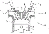
Fig. 2 is a schematic diagram showing a portion of an internal combustion engine in a cross-sectional view. In particular, the figures show the necessary parts of a cylinder 101 of an embodiment of an internal combustion engine 100.
The internal combustion engine 100 may include one or more cylinders 101, and the cylinders 101 may be arranged in any configuration, such as an in-line configuration, a V-configuration, a flat/horizontally opposed (mixer) configuration, and so forth.
As shown in fig. 2, each cylinder 1 includes a cylinder head 2, a piston 3, and a combustion chamber 1a, wherein the piston 3 is configured to reciprocate toward and away from the cylinder head 2, and the combustion chamber 1a is located between the piston 3 and the cylinder head 2. Furthermore, each cylinder 1 comprises one or more inlet valves 4 arranged in association with the combustion chamber 1a and one or more outlet valves 5 arranged in association with the combustion chamber 1 a.
An intake system 6 for delivering intake air to the engine 100 is provided in conjunction with the intake valve 4, and an exhaust system 7 for carrying exhaust gas away from the engine 100 is provided in conjunction with the exhaust valve 5.
The intake valve 4 controls inflow of intake air from the intake system 6 to the cylinder 1, and the exhaust valve 5 controls discharge of exhaust gas from the cylinder 1 to the exhaust system 7.
As shown in fig. 2, the engine 100 may include a valve actuating device 8 configured to open and close the intake valve 4. The valve actuation device 8 may be configured or controlled to allow for delayed or advanced closing of the intake valve 4 according to the miller-type valve timing principle. Similarly, the engine 100 may comprise a valve actuation device 9, the valve actuation device 9 being configured or controlled for opening and closing the exhaust valve 5, or even for delaying or advancing the opening and closing of the exhaust valve 5.
One or more of the valve actuation devices 8, 9 may be controlled to open or close the intake and exhaust valves 4, 5 according to a predetermined and/or dynamic timing schedule; including advancing the miller-type valve timing and retarding the miller-type valve timing. This will be explained further below.
In one embodiment, one valve actuation device 8, 9 operates one intake valve 4/exhaust valve 5.
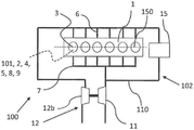
FIG. 3A schematically illustrates an internal combustion engine 100, according to an example embodiment of the invention. The engine 100 is an in-line six cylinder engine, and the engine 100 includes the components shown in fig. 2.
Fig. 3A further shows that the intake system 6 is arranged in conjunction with the intake valve 4 and the exhaust system 7 is arranged in conjunction with the exhaust valve 5.
An EGR system 102 is provided between the exhaust system 7 and the intake system 6. The EGR system comprises a gas delivery device 15 or EGR pump 15 and an EGR conduit 110 allowing fluid communication between the exhaust system 7 and the intake system 6. The gas delivery device 15 is operative to deliver and/or control the flow of exhaust gas from the exhaust system 7 to the intake system 6 via the EGR conduit 110.
The gas delivery device 15 may be driven by an EGR drive unit 22, as discussed below with reference to fig. 3B.
The engine 100 further comprises a supercharging system 12 connected to the intake system 6 to compress the intake air to a pressure higher than the pressure in the exhaust system 7 under certain operating conditions of the engine 100. In fig. 3A, the supercharging system 12 is a turbocharger including a turbine 11 and a compressor 12b. The turbine 11 is operated to drive the compressor 12b via a shaft.
The EGR system 102 is a high-pressure EGR system in which exhaust gas is branched off from the exhaust gas flow upstream of the turbine 11.
The compressor 12b is arranged to pressurise air in the intake system 6 depending on the operating conditions of the engine 100 and to provide a positive or differential pressure between the intake system 6 and the exhaust system 7 when required, while operating with retarded or advanced miller-type valve timing so that the pressure in the intake system 6 exceeds the pressure in the exhaust system 7.
As discussed below with reference to fig. 3B, a so-called waste valve may be provided to divert exhaust gas from the turbine 11 to regulate the speed of the turbine.
As discussed below with reference to fig. 3B, the pressurized intake air may be cooled in a cooler, such as a charge air cooler or intercooler.
During operation of the engine 100, a portion of the exhaust gas is branched off from the exhaust gas flow flowing in the exhaust system 7 upstream of the turbine 11 to the EGR system 102. The remaining exhaust gas is delivered to the turbine 11 of the turbocharger.
Exhaust gas divided from the exhaust gas flow is introduced into the gas delivery device 15 via the EGR conduit 110, and under certain operating conditions, the gas delivery device 15 pressurizes the exhaust gas to a pressure level corresponding to at least the absolute pressure level in the intake system 6; this is to allow exhaust gas to flow from the exhaust system 7 into the intake system 6 regardless of the pressure difference between the exhaust system 7 and the intake system 6.
As discussed below with reference to fig. 3B, the flow of gas in the EGR conduit 110 may be controlled by one or more EGR valves 10.
It should be noted that the EGR conduit system including one or more EGR conduits 110 facilitates the transport of EGR gas. EGR conduit 110 may be made of any suitable material and in any size and geometry.
FIG. 3B schematically illustrates an internal combustion engine 100, according to an example embodiment of the invention. The engine 100 includes the components shown in fig. 2 and 3A, however additional features are included.
In this embodiment, the exhaust system 7 is divided into two sections: starting from the left side of the figure, one section is for cylinders 1, 2, 3 and one section is for cylinders 4, 5, 6. The two sections of the exhaust system 7 may carry exhaust gas through an EGR valve 10, the EGR valve 10 being arranged to ensure that a portion of the exhaust gas is branched off from the exhaust system 7 and to further control the amount of exhaust gas returned as EGR to the intake system 6. The remaining exhaust gases are further conveyed to the turbine section 11 of the turbocharger.
A waste valve system 103 may be provided to divert exhaust gas away from the turbine 11 in order to adjust the turbine speed. The exhaust valve system 103 includes a valve 13, the valve 13 being operable to bypass excess pressure or excess exhaust flow around the turbine 11 to regulate the maximum boost delivered by the boost system 12.
The pressurized intake air may be cooled in a cooler 18, such as a charge air cooler or intercooler. The cooler 18 increases the efficiency of the boost system by reducing or removing the induction air heat (compression heat) and the heat of compression added to the compressed intake air by the boost system 12. In this way, the bulk density of the intake air increases.
The exhaust gases branching off from the exhaust system 7 can be conveyed via the EGR valve 10 and/or the EGR cooler 14 to the gas conveying device 15 to be pressurized to a pressure level which corresponds at least to the pressure in the intake system 6.
Under operating conditions in which the pressure in the exhaust system 7 is sufficiently high, pressurization by the gas delivery device 15 may not be necessary — and the gas delivery device 15 may be bypassed via the bypass conduit 17. A bypass valve 16 may be provided to control the flow in the bypass conduit 17. In fig. 3B, a bypass valve 16 is arranged in a bypass flow line 17. Alternatively or additionally, the gas delivery device 15 may also be freely operable with the flow of EGR gas under such conditions.
The separation of the exhaust system 7 according to the embodiment shown in fig. 3B allows pressure pulsations to remain in the exhaust system 7. One benefit of this configuration is that the retained pressure pulsations are carried to the turbine 11, thereby also propelling the turbine 11 under operating conditions that produce low or insufficient pressure in the exhaust system 7 to propel the turbine 11. In addition, as shown in fig. 3A, the non-split exhaust system provides higher exhaust back pressure, thus reducing volumetric efficiency and increasing residue in the cylinder 1.
The EGR valve 10 may be configured to divert exhaust gases from one, two, or more exhaust systems; thus, the EGR valve 10 may constitute a multi-function or dual valve. In some embodiments, the EGR valve 10 may be configured to branch off exhaust gas from only one segment of the exhaust system 7. However, this may skew engine operation and result in an uneven distribution of exhaust gas between the cylinders 1.
According to one example embodiment, gas delivery device 15 may constitute a displacement pump connected to EGR drive unit 22. The EGR driving unit 22 may be configured to drive the gas delivery device 15 in a delivery mode to deliver exhaust gas into the intake system 6.
As an example, the EGR drive unit 22 may constitute an electric motor that can function as a generator in the reverse drive mode. Alternatively, the EGR drive unit may constitute a mechanical drive, such as a belt, chain or gear drive or a hydraulic or pneumatic drive.
According to one exemplary embodiment shown in fig. 3B, an accumulator 23 (such as a battery or capacitor) is connected to the EGR drive unit 22 to store energy in the compound mode.
The EGR driving unit 22 may also be configured to back-drive the gas delivery device 15 to provide pressure to the turbine 11 to accelerate the rotation of the compressor 12b. In this way, low end performance of engine 100 may be improved. The reverse mode may be applied independently of the pressure difference between the exhaust system 7 and the intake system 6.
FIG. 3C schematically shows an embodiment of the engine 100 according to FIG. 3B, but with additional features and configured for a reverse drive mode of the EGR system 102.
In fig. 3C, the EGR system 102 is provided with a gas redirecting system 24, which gas redirecting system 24 is configured to redirect the gas flow from the gas delivery device 15 from its normal delivery direction to the turbine 11 via the redirecting system 24. The flow direction is controlled by a (redirecting) valve 25, which valve 25 is configured to close the EGR delivery flow while opening the air flow to the supercharging system 12.
The redirection system 24 may comprise conduits interconnecting the valves 25 so that the gas flow from the gas delivery device 15 may be redirected from its normal route and through a conduit to the turbine 11. The valve 25 may be connected to a control unit 26 or ECU, which control unit 26 or ECU is configured to control the opening and closing of the valve 25 depending on the driving mode.
FIG. 3C further illustrates that control unit 26 may be operative to control various devices within engine 100. The control unit 26 may be configured to obtain various input signals from a plurality of sensors, not shown. The control of the device may be dependent on the operating conditions and performed in response to software stored in a memory maintained in the control unit. As an example, the control unit may be operated to control the opening and closing of the inlet valve 4 via the valve actuating member 8, the gas delivery device 15 and the turbocharger; depending on the operating conditions, user input and drive modes including, for example, a feed mode, a compound mode, and a reverse or at least partially reverse mode.
In fig. 3C, the control unit 26 is operated to control the supercharging system 12, the valve 13 in the exhaust valve system 103, the EGR valve 10, the EGR drive unit 22, the valve actuating members 8, 9, the bypass valve 16, the valve 25 in the redirection system 24, etc., as shown.
It should be noted that the control unit 26 may be operated to control one or more devices as desired and depending on the selected embodiment of the present invention. The control unit 26 may be operable to communicate with additional controllers, communication gateways, and the like.
Furthermore, fig. 3C shows that the EGR system 102 may be connected to an EGR valve 10 arranged in the exhaust system 7 upstream of the turbine 11; thus, a high pressure EGR system 102 is shown.
FIG. 3D schematically illustrates a further example embodiment of the engine 100 with the low-pressure EGR system 102.
In fig. 3D, the EGR system 102 is shown connected to the outlet 27 arranged on the turbine 11, and the low pressure EGR valve 10b is shown arranged to control the EGR flow to the gas delivery device 15.
In further and not shown embodiments of the invention, the exhaust gas for the EGR system 102 may be branched off downstream of the turbine 11, including from a section of the exhaust gas treatment system.
Fig. 4 schematically shows the principle of retarding and advancing the miller-type valve timing for one cylinder 1 according to the invention.
The upper graph 104 shows the opening and closing curves of the intake valves.
The lower graph 105 represents the piston stroke between Top Dead Center (TDC) at 360CAD (crank angle degrees from 0 degrees at the beginning of the expansion stroke) and Bottom Dead Center (BDC) at 540 CAD.
The solid line 106 in the upper graph represents retarded miller-type valve timing. It can be seen that in retarding the miller-type valve timing, the intake valve is opened at about 360CAD and closed at about 550CAD, i.e., closed after BDC at 540 CAD; thereby indicating that the delay valve is closed.
The dashed line 107 in the upper graph indicates advancing the miller-type valve timing. It can be seen that the intake valve is open at about 360CAD and closed at about 530CAD, i.e., closed before BDC at 540 CAD; thereby indicating that the advance valve is closed.
It should be noted that fig. 4 shows only one example of retarding and advancing the miller-type valve timing. Depending on the operating conditions, different timings of opening and closing the inlet valve may be applied without departing from the scope of the invention.
According to an example embodiment of the invention, retarding the miller-type valve timing may be applied by closing the intake valve in the range 540CAD to 680CAD, preferably 540CAD to 640CAD, more preferably 540CAD to 600CAD, and most preferably 540CAD to 580 CAD. The selection of the desired range, which already shows the desired result, will depend on the operating conditions.
According to an example embodiment of the invention, advancing the miller-type valve timing may be applied by closing the intake valve in the range 500 CAD-540 CAD, preferably in the range 520 CAD-540 CAD, and most preferably in the range 530 CAD-540 CAD. The selection of the desired range, which already shows the desired result, will depend on the operating conditions.
There are different valve actuation systems, including valve actuation devices 8, 9, which allow advancing and/or retarding the miller-type valve timing. The actuation system may be a fixed valve actuation system or a variable valve actuation system. Valve actuation systems are known per se in the art, and in the context of the present invention, any suitable valve actuation system may be used to retard and advance miller-type valve timing.
Retarding the miller-type valve timing keeps the intake valve open longer than the "optimal" time at BDC for a conventional four-stroke engine (otto or diesel), thereby improving volumetric efficiency. The result of this is that the charge gas, i.e. intake air and EGR, is pushed back into the intake system by the piston; thus effectively functioning as a boost system, increasing the pressure in the intake system. This increases the pumping work but also increases the heat transfer from the cylinder and the intake port.
Advancing the miller-type valve timing, the intake valve closes before BDC and has the advantage of less loss than retarding the miller. Both advancing and retarding miller have the advantage of increasing engine efficiency by providing the same effective compression ratio and a larger expansion ratio.
FIG. 5 is a graphical representation of pressure conditions in the exhaust system, intake system, and gas delivery device.
The graph 108 shows the effective torque load of the gas delivery device 15 (delivery mode) according to CAD.
As described above, the pressurized air intake system may include a cooler 18, such as an intercooler. Typically, in the course of flowing through the cooler, a boost pressure of several kPa is lost, which means that the boost pressure in the intake system 6 will be slightly lower than the boost pressure downstream of the compressor 12b. The gas delivery device 15 performs work towards the air intake system 6 in the delivery mode, which means that the pressure at the outlet of the gas delivery device 15 will be substantially equivalent to the boost pressure in the air intake system; however, there is also a small pressure drop caused primarily by the EGR valve (if present) and any EGR cooler 14. This means that the inlet pressure of the gas delivery device 15 is slightly lower than the exhaust manifold pressure; typically a few kilopascals. The pressure drop is flow dependent so for very small flows there is substantially no pressure drop. The gas delivery device 15 is essentially required to have the same pressure ratio as that present on the engine, but with the addition of the pressure drop in the EGR cooler + EGR valve + conduit:
- [ Delta ] P gas delivery device = (P intake system-P exhaust system) + [ Delta ] P EGR system
As mentioned, the gas delivery device 15 may be any type of pump capable of delivering or pumping gas. If gas delivery device 15 constitutes a displacement pump, it will only add or receive work if there is a pressure differential across the pump. This is due to the fact that displacement pumps do not have internal compression.
The preferred type of displacement pump is a roots pump (blower), which has a continuous flow rate as opposed to an intermittent flow rate. This means that the flow is uninterrupted and flows continuously into the intake system 6 of the engine 100.
Since the gas delivery device 15 is only operated when the pressure at the outlet is higher than the pressure on the inlet side, the operation is performed by the gas delivery device 15 only when needed. Similarly, when the exhaust pressure pulses to the inlet of the gas delivery device 15, no pump operation is required. In such a scenario, the exhaust gas is only delivered to its outlet by the gas delivery device 15 without the need for work or compressed gas. In addition to this, energy can be extracted from the gas conveying device when the pressure difference is negative. This has been explained in more detail with reference to fig. 3B and 3C.
Turning again to fig. 5, various states of operation of the gas delivery device 15 are schematically shown as a result of a control function measuring the pressure in the engine 100 and possibly further input parameters (engine speed, load state) for determining the operating state. The pressure level (and possibly further parameters) is measured and the measured pressure level (and possibly further parameters) is supplied to a control unit 26 (fig. 3D), which control unit 26 determines the operation mode of the gas delivery device 15 on the basis of the measured results. As described above, the operating mode may be EGR delivery or an EGR complex, i.e., energy recovery. In the latter case, the recovered energy may be transferred back to the engine or stored in an energy storage device for later use.
Fig. 6A schematically shows the main steps of operating an internal combustion engine according to the invention. These steps are described with reference to an internal combustion engine as described with reference to fig. 1 to 5. The steps are as follows:
-a step S1: a portion of the exhaust gas flow is branched off from the exhaust system 7, to be returned to the intake system 6 via the EGR system 102,
-a step S2: the branched exhaust gas flow is conveyed to the intake system 6,
-a step S3: the intake system 6 is pressurized via the supercharging system 12 to a level above the exhaust pressure,
-a step S4: the intake valves 4 of the cylinders 1 are opened, and the intake valves 4 are maintained open to retard or advance the closing of the intake valves 4.
According to an exemplary embodiment of step S4, the delayed closing step involves keeping the intake valve open until crankshaft 150 reaches a range of 540CAD to 680CAD, preferably 540CAD to 640CAD, more preferably 540CAD to 600CAD, and most preferably from 540CAD to 580 CAD.
According to an exemplary embodiment of step S4, the early closing step involves keeping the intake valve open, crankshaft 150 to a range of 500CAD to 540CAD, preferably 520CAD to 540CAD, and most preferably 530CAD to 540 CAD.
FIG. 6B schematically illustrates an example embodiment of the method shown in FIG. 6A; but with the following steps:
-a step S5: before S2, the branched portion of the exhaust gas is pressurized by operating the gas delivery device 15 in a delivery mode depending on the operating parameters of the engine 100 and different operating modes.
FIG. 6C schematically illustrates an example embodiment of the method shown in FIG. 6A; however, under operating conditions in which the exhaust pressure is higher than the intake pressure. This embodiment comprises the following further steps:
-a step S6: the bypass valve 16 is opened, whereby the gas delivery device 15 is bypassed when the exhaust gas pressure in the exhaust system 7 exceeds the pressure in the intake system 6.
Fig. 6D schematically shows an exemplary embodiment of the method shown in fig. 6A, comprising the following further steps:
-a step S7: when the exhaust gas pressure in the exhaust system 7 is higher than the pressure in the intake system 6 to drive the gas delivery device 15 and thereby the EGR drive unit 22, the gas delivery device 15 is set to the compound mode to generate power output.
-a step S8: to an accumulator (e.g., a battery or a capacitor) connected to EGR drive unit 22, or to engine 100.
FIG. 6E schematically illustrates an example embodiment of a method according to the invention, wherein the method is configured to provide pressure to the pressurization system 12.
The method comprises the following steps:
-a step S9: the EGR driving unit 22 is set to drive the gas delivery device 15 to provide pressure to the supercharging system 12.
In this embodiment, the gas delivery device 15 may draw a supply gas from the intake system or from the exhaust system.
Fig. 6F schematically shows an example embodiment of the method shown in fig. 6A as an alternative to the method shown in fig. 6E and with the following further steps:
-a step S10: valve 25 in redirection system 24 is controlled to close EGR delivery and open valve 25 which controls airflow to boost system 12.
Fig. 7A and 7B schematically show a flow chart illustrating two operating modes of the internal combustion engine 100 operating according to the second aspect of the present invention. A second aspect of the invention relates to a method of increasing the efficiency of an internal combustion engine.
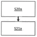
Fig. 7A is a flowchart showing a first mode of operation, which includes the steps of:
-a step S20a: the internal combustion engine 100 is operated under conditions where the pressure in the intake system 6 exceeds or is substantially similar to the pressure in the exhaust system 7,
-a step S21a: the gas delivery device 15 is operated so as to pressurize the branched exhaust gas and thereby supply the branched exhaust gas to the intake system 6.
FIG. 7B is a flow chart illustrating a second mode of operation; the second mode includes the steps of:
-a step S20b: operating the internal combustion engine 100 under conditions in which the pressure in the exhaust system 7 is higher than the pressure in the intake system 6, and
-a step S21b: the EGR system 102 and/or the EGR drive unit 22 are configured to be driven by the gas delivery device 15, so as to generate a power output,
-a step S22b: the engine 100 is operated so as to drive the gas delivery device 15 by exhaust gas flowing from the exhaust system 7 to the intake system 6, and thereby operate the gas delivery device 15 in an energy recovery mode in which the EGR drive unit 22 generates a power output.
In some embodiments, the method according to the second aspect of the invention may be configured for switching between a first mode of operation and a second mode of operation.
It is to be understood that the invention is not limited to the embodiments described above and shown in the drawings; on the contrary, those skilled in the art will recognize that many changes and modifications may be made within the scope of the appended claims.
Claims (6)
1. A method of increasing the efficiency of an internal combustion engine (100), wherein the internal combustion engine comprises: a crankshaft (150); one or more cylinders (1), said one or more cylinders (1) comprising a cylinder head (2), a piston (3), a combustion chamber (1 a); one or more intake valves (4), the one or more intake valves (4) operating according to retarding or advancing Miller-type valve timing; one or more exhaust valves (5); an air intake system (6), the air intake system (6) being configured for delivering intake air to the internal combustion engine (100); an exhaust system (7), the exhaust system (7) being configured for carrying exhaust gases away from the internal combustion engine (100); an EGR system (102), the EGR system (102) comprising a gas delivery device (15) connected to an EGR driver unit (22) and being configured to deliver exhaust branched off from the exhaust system (7) through an EGR conduit (110) and to deliver branched off exhaust into the intake system (6); and a supercharging system (12), the supercharging system (12) being connected to the intake system (6), wherein the gas delivery device (15) is a displacement pump, and wherein the displacement pump is arranged in the EGR duct (110) between the exhaust system (7) and the intake system (6), characterized in that the method comprises the following steps:
-operating (S20 a) the internal combustion engine (100) on condition that the pressure in the intake system (6) exceeds the pressure in the exhaust system (7), and
-operating (S21 a) the gas delivery device (15) so as to pressurize the branched exhaust gas and thereby supply the branched exhaust gas to the intake system (6),
or
-operating (S20 b) the internal combustion engine (100) under conditions where the pressure in the exhaust system (7) is higher than the pressure in the intake system (6),
-configuring (S21 b) the EGR system (102) and/or the EGR drive unit (22) to be driven by the gas delivery arrangement (15) for generating a power output,
-operating (S22 b) the internal combustion engine (100) to drive the gas delivery device (15) by exhaust gas flowing from the exhaust system (7) to the intake system (6), thereby operating the gas delivery device (15) in an energy recovery mode in which the EGR drive unit (22) generates a power output,
wherein the method comprises the following steps:
-operating the EGR system (102) in an at least partially reverse mode under operating conditions in which the pressure in the exhaust system (7) is lower than the pressure in the intake system (6) or under operating conditions in which the turbine (11) of the supercharging system (12) is operating at a lower than required speed, such that the gas delivery device (15) supplies pressure to the supercharging system (12),
the method comprises the following steps:
-operating a redirecting system (24), the redirecting system (24) being configured to close an EGR delivery flow by operating a valve (25) in the redirecting system (24) and to open any valve (25) to the supercharging system (12) so as to redirect exhaust gas from the gas delivery device (15) to the turbine (11).
2. A method according to claim 1, wherein the method of operating the internal combustion engine (100) under conditions where the pressure in the exhaust system (7) is higher than the pressure in the intake system (6) comprises the steps of:
-delivering the output power to an accumulator (23) or to the internal combustion engine (100).
3. An internal combustion engine (100) comprising: a crankshaft (150); one or more cylinders (1), said one or more cylinders (1) comprising a cylinder head (2), a piston (3), a combustion chamber (1 a); one or more intake valves (4), the one or more intake valves (4) operating according to retarding or advancing Miller-type valve timing; one or more exhaust valves (5); an air intake system (6), the air intake system (6) being configured for delivering intake air to the internal combustion engine (100); an exhaust system (7), the exhaust system (7) being configured for carrying exhaust gases away from the internal combustion engine (100); an EGR system (102), the EGR system (102) comprising a gas delivery device (15) connected to an EGR driver unit (22) and being configured to deliver exhaust branched off from the exhaust system (7) through an EGR conduit (110) and to deliver branched off exhaust into the intake system (6); and a supercharging system (12), the supercharging system (12) being connected to the intake system (6), wherein the gas delivery device (15) is a displacement pump, and wherein the displacement pump is arranged in the EGR duct (110) between the exhaust system (7) and the intake system (6), wherein the internal combustion engine (100) is configured to perform the method according to any one of claims 1 to 2.
4. A computer readable medium carrying a computer program comprising program code means for performing the steps of the method according to any one of claims 1-2 when said computer program is run on a computer.
5. A control unit (26) configured to perform the steps of the method according to any one of claims 1 to 2.
6. A vehicle comprising an internal combustion engine (100) according to claim 3.
Applications Claiming Priority (1)
| Application Number | Priority Date | Filing Date | Title |
|---|---|---|---|
| PCT/EP2018/067546 WO2020001780A1 (en) | 2018-06-29 | 2018-06-29 | An internal combustion engine |
Publications (2)
| Publication Number | Publication Date |
|---|---|
| CN112334645A CN112334645A (en) | 2021-02-05 |
| CN112334645B true CN112334645B (en) | 2022-10-28 |
Family
ID=62842085
Family Applications (2)
| Application Number | Title | Priority Date | Filing Date |
|---|---|---|---|
| CN201880095166.2A Active CN112334645B (en) | 2018-06-29 | 2018-06-29 | Internal combustion engine |
| CN201980043739.1A Pending CN112384690A (en) | 2018-06-29 | 2019-06-28 | Internal combustion engine |
Family Applications After (1)
| Application Number | Title | Priority Date | Filing Date |
|---|---|---|---|
| CN201980043739.1A Pending CN112384690A (en) | 2018-06-29 | 2019-06-28 | Internal combustion engine |
Country Status (4)
| Country | Link |
|---|---|
| US (2) | US11421611B2 (en) |
| EP (2) | EP3814623B1 (en) |
| CN (2) | CN112334645B (en) |
| WO (2) | WO2020001780A1 (en) |
Families Citing this family (11)
| Publication number | Priority date | Publication date | Assignee | Title |
|---|---|---|---|---|
| WO2020001780A1 (en) * | 2018-06-29 | 2020-01-02 | Volvo Truck Corporation | An internal combustion engine |
| EP3981979A1 (en) * | 2020-10-07 | 2022-04-13 | Volvo Truck Corporation | An internal combustion engine system |
| US20240003319A1 (en) * | 2020-11-04 | 2024-01-04 | Eaton Intelligent Power Limited | Egr pump locking mechanism and method to lock egr pump rotating group during engine braking |
| CN112523903A (en) * | 2020-12-01 | 2021-03-19 | 广西玉柴机器股份有限公司 | In-cylinder water spraying control method |
| US11846257B2 (en) | 2021-05-03 | 2023-12-19 | Deere & Company | Engine system with reversible exhaust gas recirculation pump for controlling bypass flow |
| US11591992B2 (en) * | 2021-05-05 | 2023-02-28 | Deere & Company | Engine system with air pump for enhanced turbocharger air exchange |
| US11572824B2 (en) | 2021-05-13 | 2023-02-07 | Deere & Company | Electrified engine boost components for mitigating engine stalling in a work vehicle |
| US11536213B2 (en) | 2021-05-19 | 2022-12-27 | Deere & Company | Engine system with electrified air system components for managing emissions of nitrogen oxides in a work vehicle |
| US11572673B2 (en) * | 2021-06-25 | 2023-02-07 | Deere & Company | Work vehicle power system with decoupled engine air system components |
| WO2023001407A1 (en) * | 2021-07-21 | 2023-01-26 | Eaton Intelligent Power Limited | Egr pump pulse synchronization |
| US11939929B2 (en) | 2021-08-19 | 2024-03-26 | Deere &Company | Engine electrified air system including electric turbocharger and exhaust gas recirculation pump |
Family Cites Families (61)
| Publication number | Priority date | Publication date | Assignee | Title |
|---|---|---|---|---|
| US2041445A (en) | 1934-04-14 | 1936-05-19 | Pulsometer Eng Co | Lockable freewheel transmission mechanism |
| US4231225A (en) * | 1979-02-05 | 1980-11-04 | Aya Kazim K | Turbocharged engine with pressurized gas recirculation |
| JPS55156243A (en) * | 1979-05-22 | 1980-12-05 | Nissan Motor Co Ltd | Cylinder fuel injection engine |
| DK170218B1 (en) * | 1993-06-04 | 1995-06-26 | Man B & W Diesel Gmbh | Large pressurized diesel engine |
| US7281527B1 (en) * | 1996-07-17 | 2007-10-16 | Bryant Clyde C | Internal combustion engine and working cycle |
| US6230683B1 (en) * | 1997-08-22 | 2001-05-15 | Cummins Engine Company, Inc. | Premixed charge compression ignition engine with optimal combustion control |
| US6216458B1 (en) * | 1997-03-31 | 2001-04-17 | Caterpillar Inc. | Exhaust gas recirculation system |
| JP3674254B2 (en) * | 1997-08-21 | 2005-07-20 | いすゞ自動車株式会社 | EGR device for supercharged engine |
| US6164071A (en) * | 1997-09-08 | 2000-12-26 | Cummins Engine Company, Inc. | EGR delivery and control system using dedicated full authority compressor |
| US20020195086A1 (en) * | 1997-12-16 | 2002-12-26 | Beck N. John | Cylinder pressure based optimization control for compression ignition engines |
| US6273076B1 (en) * | 1997-12-16 | 2001-08-14 | Servojet Products International | Optimized lambda and compression temperature control for compression ignition engines |
| US6354268B1 (en) * | 1997-12-16 | 2002-03-12 | Servojet Products International | Cylinder pressure based optimization control for compression ignition engines |
| DE19833467C2 (en) * | 1998-07-24 | 2000-05-04 | Koenig & Bauer Ag | Offset rotary printing machine |
| JP3998861B2 (en) * | 1999-06-16 | 2007-10-31 | 株式会社小松製作所 | Exhaust gas recirculation device and control method thereof |
| AT3753U1 (en) * | 1999-06-24 | 2000-07-25 | Avl List Gmbh | INTERNAL COMBUSTION ENGINE, IN PARTICULAR WITH AUTO IGNITION |
| US7347171B2 (en) * | 2002-02-04 | 2008-03-25 | Caterpillar Inc. | Engine valve actuator providing Miller cycle benefits |
| US20030154716A1 (en) * | 2002-02-21 | 2003-08-21 | Detroit Diesel Corporation | Exhaust gas recirculation system |
| AT7207U1 (en) * | 2002-10-22 | 2004-11-25 | Avl List Gmbh | METHOD FOR OPERATING A DIRECTLY INJECTING DIESEL INTERNAL COMBUSTION ENGINE |
| US7415963B2 (en) * | 2003-10-09 | 2008-08-26 | Avl List Gmbh | Method for operating an internal combustion engine |
| US7788923B2 (en) * | 2006-02-02 | 2010-09-07 | International Engine Intellectual Property Company, Llc | Constant EGR rate engine and method |
| US20070220885A1 (en) * | 2006-03-22 | 2007-09-27 | David Turner | EGR energy recovery system |
| JP4253339B2 (en) | 2006-09-21 | 2009-04-08 | 株式会社日立製作所 | Control device for internal combustion engine |
| US20120137679A1 (en) * | 2006-12-11 | 2012-06-07 | Dytech Ensa, S.L. | Internal combustion engine egr apparatus |
| US8176736B2 (en) * | 2008-03-21 | 2012-05-15 | Cummins Inc. | EGR apparatuses, systems, and methods |
| US20090249783A1 (en) * | 2008-04-04 | 2009-10-08 | General Electric Company | Locomotive Engine Exhaust Gas Recirculation System and Method |
| GB2464500B (en) * | 2008-10-17 | 2013-02-20 | Cummins Turbo Tech Ltd | An internal combustion engine with exhaust gas recirculation |
| EP2196659A1 (en) * | 2008-12-10 | 2010-06-16 | ABB Turbo Systems AG | Two-stage charging system for exhaust gas circulation |
| US20100146968A1 (en) * | 2008-12-12 | 2010-06-17 | Alexander Simpson | Emission system, apparatus, and method |
| US20100146967A1 (en) * | 2008-12-12 | 2010-06-17 | Alexander Simpson | Emission system, apparatus, and method |
| ATE552417T1 (en) * | 2009-02-16 | 2012-04-15 | Caterpillar Motoren Gmbh & Co | TURBOCHARGED ENGINE WITH EXHAUST GAS RECYCLING |
| US9062633B2 (en) | 2009-08-01 | 2015-06-23 | Electro-Motive Diesel, Inc. | Pressure balanced exhaust gas recirculation assembly for a locomotive two-stroke uniflow scavenged diesel engine |
| US20110094224A1 (en) * | 2009-10-28 | 2011-04-28 | Sheidler Alan D | Metering exhaust gas recirculation system for a turbocharged engine having a turbogenerator system |
| US8522757B2 (en) * | 2009-10-28 | 2013-09-03 | Deere & Company | Metering exhaust gas recirculation system for a dual turbocharged engine having a turbogenerator system |
| US8522756B2 (en) * | 2009-10-28 | 2013-09-03 | Deere & Company | Interstage exhaust gas recirculation system for a dual turbocharged engine having a turbogenerator system |
| DE102010043027B4 (en) * | 2010-10-27 | 2019-08-14 | Mtu Friedrichshafen Gmbh | Internal combustion engine |
| US9021808B2 (en) * | 2011-01-10 | 2015-05-05 | Cummins Intellectual Property, Inc. | Rankine cycle waste heat recovery system |
| US20130174548A1 (en) * | 2011-05-16 | 2013-07-11 | Achates Power, Inc. | EGR for a Two-Stroke Cycle Engine without a Supercharger |
| JP5929015B2 (en) | 2011-06-06 | 2016-06-01 | 日産自動車株式会社 | Exhaust gas recirculation device for internal combustion engine |
| US9181905B2 (en) * | 2011-09-25 | 2015-11-10 | Cummins Inc. | System for controlling an air handling system including an electric pump-assisted exhaust gas recirculation |
| US8783015B2 (en) * | 2011-12-15 | 2014-07-22 | Ecomotors, Inc. | Shared EGR system and method for a dual-module engine |
| US20150114366A1 (en) * | 2012-04-05 | 2015-04-30 | The Ohio State University | Systems and methods for implementing an open thermodynamic cycle for extracting energy from a gas |
| DK177700B1 (en) | 2012-04-19 | 2014-03-24 | Man Diesel & Turbo Deutschland | A large slow running turbocharged two stroke internal combustion engine with crossheads and exhaust- or combustion gas recirculation |
| US8997484B2 (en) * | 2012-05-17 | 2015-04-07 | Ford Global Technologies, Llc | Boost reservoir control |
| US9528429B2 (en) * | 2012-05-17 | 2016-12-27 | Ford Global Technologies, Llc | Boost reservoir EGR control |
| FR2991725B1 (en) * | 2012-06-11 | 2017-12-15 | Valeo Systemes De Controle Moteur | ASSEMBLY COMPRISING A THERMAL MOTOR AND AN ELECTRIC COMPRESSOR |
| JP5893549B2 (en) | 2012-12-20 | 2016-03-23 | 川崎重工業株式会社 | EGR device and engine system |
| JP2016003585A (en) | 2014-06-16 | 2016-01-12 | 日産自動車株式会社 | Cooling device for internal combustion engine |
| FR3022946B1 (en) * | 2014-06-26 | 2019-06-28 | Valeo Systemes De Controle Moteur | ENGINE SYSTEM WITH BURN GAS RECIRCULATION CIRCUIT |
| US9541017B2 (en) * | 2014-10-07 | 2017-01-10 | Ford Global Technologies, Llc | Throttle bypass turbine with exhaust gas recirculation |
| DE102014224474B4 (en) * | 2014-12-01 | 2019-06-06 | Continental Automotive Gmbh | Charging device for an internal combustion engine and operating method for the charging device |
| US9664148B2 (en) * | 2015-03-31 | 2017-05-30 | Electro-Motive Diesel, Inc. | Engine system having increased pressure EGR system |
| DK178748B1 (en) | 2015-05-12 | 2016-12-19 | Man Diesel & Turbo Filial Af Man Diesel & Turbo Se Tyskland | A large turbocharged two-stroke self-igniting internal combustion engine with an egr control system |
| US9989020B2 (en) * | 2015-05-15 | 2018-06-05 | Ford Global Technologies, Llc | Auto-ignition internal combustion engine with exhaust-gas turbocharging and exhaust-gas recirculation |
| WO2016206720A1 (en) | 2015-06-23 | 2016-12-29 | Volvo Truck Corporation | An internal combustion engine system |
| AT518400B1 (en) | 2016-02-10 | 2017-10-15 | Avl List Gmbh | INTERNAL COMBUSTION ENGINE WITH SEVERAL CYLINDERS |
| DE102017003285A1 (en) * | 2017-04-04 | 2018-10-04 | GM Global Technology Operations LLC (n. d. Ges. d. Staates Delaware) | Gas guide for an internal combustion engine |
| KR102440599B1 (en) * | 2017-11-02 | 2022-09-05 | 현대자동차 주식회사 | Control system of electric supercharger and control method for the same |
| EP3814618B1 (en) * | 2018-06-29 | 2023-07-19 | Volvo Truck Corporation | A method of operating a four stroke internal combustion engine system |
| WO2020001780A1 (en) * | 2018-06-29 | 2020-01-02 | Volvo Truck Corporation | An internal combustion engine |
| WO2020038576A1 (en) * | 2018-08-23 | 2020-02-27 | Volvo Truck Corporation | A method for operating an internal combustion engine system |
| KR20200093949A (en) * | 2019-01-29 | 2020-08-06 | 현대자동차주식회사 | Engine system |
-
2018
- 2018-06-29 WO PCT/EP2018/067546 patent/WO2020001780A1/en active Application Filing
- 2018-06-29 EP EP18737849.2A patent/EP3814623B1/en active Active
- 2018-06-29 CN CN201880095166.2A patent/CN112334645B/en active Active
- 2018-06-29 US US17/256,498 patent/US11421611B2/en active Active
-
2019
- 2019-06-28 WO PCT/EP2019/067287 patent/WO2020002571A1/en active Application Filing
- 2019-06-28 EP EP19733049.1A patent/EP3814624B1/en active Active
- 2019-06-28 CN CN201980043739.1A patent/CN112384690A/en active Pending
- 2019-06-28 US US17/256,511 patent/US11754005B2/en active Active
Also Published As
| Publication number | Publication date |
|---|---|
| CN112334645A (en) | 2021-02-05 |
| EP3814624A1 (en) | 2021-05-05 |
| WO2020002571A1 (en) | 2020-01-02 |
| WO2020001780A1 (en) | 2020-01-02 |
| US11421611B2 (en) | 2022-08-23 |
| CN112384690A (en) | 2021-02-19 |
| US11754005B2 (en) | 2023-09-12 |
| EP3814624C0 (en) | 2023-08-23 |
| EP3814623A1 (en) | 2021-05-05 |
| EP3814623C0 (en) | 2023-08-16 |
| US20210231065A1 (en) | 2021-07-29 |
| US20210277849A1 (en) | 2021-09-09 |
| EP3814624B1 (en) | 2023-08-23 |
| EP3814623B1 (en) | 2023-08-16 |
Similar Documents
| Publication | Publication Date | Title |
|---|---|---|
| CN112334645B (en) | Internal combustion engine | |
| EP2715087B1 (en) | Supercharged turbocompound engine apparatus | |
| JP4623064B2 (en) | Control device for an internal combustion engine with a supercharger | |
| EP2347108B1 (en) | An exhaust arrangement for an internal combustion engine | |
| JP4877200B2 (en) | Control device for internal combustion engine | |
| US8281587B2 (en) | Supercharged boost-assist engine brake | |
| EP3179079B1 (en) | Engine system | |
| US6279320B1 (en) | Turbocharging device for an internal combustion engine | |
| US9435295B2 (en) | Method for operating a volume-controlled internal-combustion engine, and an internal-combustion engine | |
| GB2430708A (en) | Turbocharging in a variable displacement i.c. engine, ie having cylinders selectively disabled | |
| US20130233289A1 (en) | Supercharged Internal Combustion Engine | |
| WO2006051299A1 (en) | A pressure-charged gasoline internal combustion engine | |
| US6966183B2 (en) | Supercharged internal combustion engine | |
| GB2507061A (en) | Method of two-stage turbocharger matching for supporting cylinder deactivation. | |
| CN109209625B (en) | Supercharged internal combustion engine | |
| GB2423797A (en) | An internal combustion engine having a turbocompounder | |
| CN102392732A (en) | Multi-valve bypass valve assembly for two stages of supercharging | |
| JP5678580B2 (en) | Control device for internal combustion engine | |
| Bontemps¹ et al. | SC-VNTTM a route toward high efficiency for gasoline engines |
Legal Events
| Date | Code | Title | Description |
|---|---|---|---|
| PB01 | Publication | ||
| PB01 | Publication | ||
| SE01 | Entry into force of request for substantive examination | ||
| SE01 | Entry into force of request for substantive examination | ||
| GR01 | Patent grant | ||
| GR01 | Patent grant |