CN112331952A - Battery liquid cooling plate structure - Google Patents
Battery liquid cooling plate structure Download PDFInfo
- Publication number
- CN112331952A CN112331952A CN202011111494.2A CN202011111494A CN112331952A CN 112331952 A CN112331952 A CN 112331952A CN 202011111494 A CN202011111494 A CN 202011111494A CN 112331952 A CN112331952 A CN 112331952A
- Authority
- CN
- China
- Prior art keywords
- cylinders
- flow
- runner
- plate structure
- equal
- Prior art date
- Legal status (The legal status is an assumption and is not a legal conclusion. Google has not performed a legal analysis and makes no representation as to the accuracy of the status listed.)
- Granted
Links
Images


Classifications
-
- H—ELECTRICITY
- H01—ELECTRIC ELEMENTS
- H01M—PROCESSES OR MEANS, e.g. BATTERIES, FOR THE DIRECT CONVERSION OF CHEMICAL ENERGY INTO ELECTRICAL ENERGY
- H01M10/00—Secondary cells; Manufacture thereof
- H01M10/60—Heating or cooling; Temperature control
- H01M10/61—Types of temperature control
- H01M10/613—Cooling or keeping cold
-
- H—ELECTRICITY
- H01—ELECTRIC ELEMENTS
- H01M—PROCESSES OR MEANS, e.g. BATTERIES, FOR THE DIRECT CONVERSION OF CHEMICAL ENERGY INTO ELECTRICAL ENERGY
- H01M10/00—Secondary cells; Manufacture thereof
- H01M10/60—Heating or cooling; Temperature control
- H01M10/61—Types of temperature control
- H01M10/617—Types of temperature control for achieving uniformity or desired distribution of temperature
-
- H—ELECTRICITY
- H01—ELECTRIC ELEMENTS
- H01M—PROCESSES OR MEANS, e.g. BATTERIES, FOR THE DIRECT CONVERSION OF CHEMICAL ENERGY INTO ELECTRICAL ENERGY
- H01M10/00—Secondary cells; Manufacture thereof
- H01M10/60—Heating or cooling; Temperature control
- H01M10/62—Heating or cooling; Temperature control specially adapted for specific applications
- H01M10/625—Vehicles
-
- H—ELECTRICITY
- H01—ELECTRIC ELEMENTS
- H01M—PROCESSES OR MEANS, e.g. BATTERIES, FOR THE DIRECT CONVERSION OF CHEMICAL ENERGY INTO ELECTRICAL ENERGY
- H01M10/00—Secondary cells; Manufacture thereof
- H01M10/60—Heating or cooling; Temperature control
- H01M10/65—Means for temperature control structurally associated with the cells
- H01M10/655—Solid structures for heat exchange or heat conduction
- H01M10/6554—Rods or plates
-
- H—ELECTRICITY
- H01—ELECTRIC ELEMENTS
- H01M—PROCESSES OR MEANS, e.g. BATTERIES, FOR THE DIRECT CONVERSION OF CHEMICAL ENERGY INTO ELECTRICAL ENERGY
- H01M10/00—Secondary cells; Manufacture thereof
- H01M10/60—Heating or cooling; Temperature control
- H01M10/65—Means for temperature control structurally associated with the cells
- H01M10/655—Solid structures for heat exchange or heat conduction
- H01M10/6556—Solid parts with flow channel passages or pipes for heat exchange
-
- H—ELECTRICITY
- H01—ELECTRIC ELEMENTS
- H01M—PROCESSES OR MEANS, e.g. BATTERIES, FOR THE DIRECT CONVERSION OF CHEMICAL ENERGY INTO ELECTRICAL ENERGY
- H01M10/00—Secondary cells; Manufacture thereof
- H01M10/60—Heating or cooling; Temperature control
- H01M10/65—Means for temperature control structurally associated with the cells
- H01M10/656—Means for temperature control structurally associated with the cells characterised by the type of heat-exchange fluid
- H01M10/6567—Liquids
-
- Y—GENERAL TAGGING OF NEW TECHNOLOGICAL DEVELOPMENTS; GENERAL TAGGING OF CROSS-SECTIONAL TECHNOLOGIES SPANNING OVER SEVERAL SECTIONS OF THE IPC; TECHNICAL SUBJECTS COVERED BY FORMER USPC CROSS-REFERENCE ART COLLECTIONS [XRACs] AND DIGESTS
- Y02—TECHNOLOGIES OR APPLICATIONS FOR MITIGATION OR ADAPTATION AGAINST CLIMATE CHANGE
- Y02E—REDUCTION OF GREENHOUSE GAS [GHG] EMISSIONS, RELATED TO ENERGY GENERATION, TRANSMISSION OR DISTRIBUTION
- Y02E60/00—Enabling technologies; Technologies with a potential or indirect contribution to GHG emissions mitigation
- Y02E60/10—Energy storage using batteries
Abstract
The invention discloses a liquid cooling plate structure of a battery, which comprises a plate substrate, wherein the plate substrate is hollowed to form a flow cavity, a plurality of cylinders which are arranged at intervals are arranged in the flow cavity, the cylinders are arranged in multiple rows and multiple columns in the flow cavity, and the flow cavity is divided by the cylinders to form a plurality of flow channels which are mutually communicated and have different cross sections; and the runner inlet and the runner outlet are arranged on the plate substrate, the runner inlet and the runner outlet are respectively communicated with the flow cavity, and the cross section of the runner close to the runner inlet is larger than that of the runner close to the runner outlet. The cooling liquid flows in the flow channel with the constantly changing cross section, and the cylinder constantly shunts and disturbs the cooling liquid, enhances the heat exchange effect of the cooling liquid and enables the cooling liquid to fully reach all areas of the flow channel. By adopting the liquid cooling plate structure of the battery, the highest temperature of the power battery is obviously reduced under the same heat production condition, and the temperature uniformity is obviously improved.
Description
Technical Field
The invention relates to the field of battery thermal management of new energy vehicles, in particular to a battery liquid cooling plate structure.
Background
The battery cooling system is responsible for taking away a large amount of heat released by the automobile power battery in the charging and discharging processes, so that the temperature of the power battery is controllable and uniform. The cooling modes include phase change cooling, air cooling, and mainstream liquid cooling. In the liquid cooling system, the reasonable design of the liquid cooling plate micro-channel can greatly improve the highest temperature value and the uniformity of each point of the battery, thereby avoiding the accumulation of excessive battery reaction heat and preventing the occurrence of heat escape. Currently, the main technical solution of the liquid cooling plate microchannel structure includes a serpentine microchannel and a parallel microchannel.
Wherein, among the snakelike microchannel structure scheme, the cooling liquid gets into the liquid cooling plate runner back through the water inlet that is located the liquid cooling plate edge, and along the circuitous flow of multistage mutually perpendicular's runner, the delivery port from liquid cooling plate other end edge flows at last. In any section of the vertical flow direction, the flow channels in one direction are obviously longer than the flow channels in the other direction, the longer flow channels are main flow channels for the cooling liquid to flow, and the shorter flow channels are mainly used for providing connection for changing the flow direction of the next section of the long flow channels, so that the whole liquid cooling plate is covered. Smooth rounded corners are often used for joining each section of flow channel to reduce flow resistance.
Although serpentine microchannel designs can cover the entire cooling range well, the channel lengths tend to be longer. In the rear section of the flow channel, the temperature of the cooling liquid is greatly increased compared with that in the front section, and the cooling efficiency is poor. Meanwhile, the problem of larger flow resistance is brought by long-distance flow, the flow speed of the rear section is reduced, and the requirement on the power of the pump is higher. The practical snake-shaped micro-channel design scheme of mass production still needs to solve the problems.
In the structure of a typical parallel flow channel scheme, cooling liquid enters a flow distribution microchannel after flowing in from a water inlet positioned at the top of a liquid cooling plate, the flow distribution microchannel is provided with n openings and is connected with n main cooling flow channels (generally, n is more than or equal to 2). The cooling liquid flows through the main cooling flow channel, is converged into a flow collecting micro-channel after being cooled, and flows out through a water outlet positioned at the edge of the bottom of the liquid cooling plate.
At present, the parallel flow channel scheme has the following defects in application. When the number n of the flow channels is smaller, the interval between the flow channels is too large, and the temperature uniformity of the battery cannot be guaranteed; when the number n of the flow channels is a large value, the flow rate of the flow channel far away from the water inlet is far smaller than that of the flow channel at the water inlet, namely the cooling effect of the edges of the two sides of the battery is far worse than that of the central flow channel. Meanwhile, with the increase of the number of the flow channels, the requirement on the flow rate of the cooling liquid is also increased, so that the overall economy of the cooling system is negatively influenced.
Disclosure of Invention
The invention aims to provide a battery liquid cooling plate structure which can enhance fluid disturbance so as to improve heat exchange performance and further solve the problems of overhigh temperature and poor balance of a power battery.
The technical scheme adopted by the invention is as follows: a battery liquid-cooled plate structure comprising:
the flow device comprises a plate base body, wherein the inside of the plate base body is hollowed to form a flow cavity, a plurality of cylinders which are arranged at intervals are arranged in the flow cavity, the cylinders are arranged in multiple rows and multiple columns in the flow cavity, and the flow cavity is divided by the cylinders to form a plurality of flow channels which are mutually communicated and have different cross sections; and
and the runner inlet and the runner outlet are arranged on the plate substrate, the runner inlet and the runner outlet are respectively communicated with the flow cavity, and the cross section of the runner close to the runner inlet is larger than the cross section of the runner close to the runner outlet.
Further, the diameters of the cylinders of the rows and/or the diameters of the cylinders of the columns are set to be different.
Further, the size and arrangement of the cylinders in the flow chamber are changed regularly, and a parameter A is introduced to define:
wherein the content of the first and second substances, the average diameter of all cylinders in the flow cavity, t is the depth of the flow channel, and A is more than or equal to 3 and less than or equal to 8;
defining the maximum diameter of the cylinder as dMaxWherein
Defining the number of cylinders in each row as m and the number of cylinders in each column as n, then:

where W is the width of the flow chamber, L is the length of the flow chamber, and m and n are rounded down.
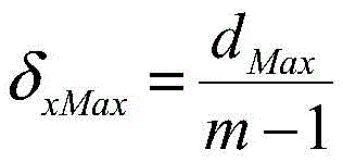
Further, the diameter of each row of cylinders gradually increases, and the maximum increment is defined as deltaxMaxWherein:

defining an optimal increment as deltax,δx=BδxMaxWherein the value range of the parameter B is more than or equal to 0.3 and less than or equal to 0.8, and the radius change of the cylinders in each row meets the following requirements:
d(j+1)-d(j)=δx
wherein the integer j satisfies 1. ltoreq. j.ltoreq.m-1, and d (j) represents the diameter of the cylinder on the j-th column.
Further, the diameter of each column of cylinders gradually increases, and the maximum increment is defined as deltayMaxWherein:

defining an optimal increment as deltay,δy=CδyMaxWherein the value range of the parameter C is more than or equal to 0.3 and less than or equal to 0.8, and the radius change of the inner cylinders in each row meets the following requirements:
d(i+1)-d(i)=δy
wherein the integer i satisfies 1. ltoreq. i.ltoreq.n-1, and d (i) represents the diameter of the cylinder on the i-th row.
Further, the diameter of the cylinders of each row and each column is gradually increased, and the maximum increment is defined as deltaxyMaxWherein:

defining an optimal increment as deltaxy,δxy=DδxyMaxWherein the value range of the parameter D is more than or equal to 0.3 and less than or equal to 0.8, and the radius change of the cylinders on each row and each column meets the following requirements:
d(i,j+1)-d(i,j)=δxy;
d(i+1,j)-d(i,j)=mδxy;
wherein the integer i, j satisfies 1 ≤ i ≤ n-1, 1 ≤ j ≤ m-1, and d (i, j) represents the diameter of the cylinder at the ith row and the jth column.
Further, the flow channel inlet and the flow channel outlet are diagonally arranged.
Further, the depth of the flow channel is equal to the height of the cylinder.
Further, the distance between the transverse centers and the longitudinal centers of the adjacent cylinders is equal.
Further, corners of the flow cavity are all provided with a round corner structure.
Has the advantages that: in this battery liquid cold plate structure, a plurality of cylinders that multirow multiseriate was arranged separate the chamber that flows and form many runners that communicate each other and the cross section is different, and the coolant liquid flows in the runner that the cross-section constantly changes, can make the coolant liquid velocity of flow increase to effectively improve the heat transfer effect that easily becomes the coolant liquid dead angle. Meanwhile, the cooling liquid is continuously distributed and disturbed by the cylinders which are densely distributed, so that the heat exchange effect of the cooling liquid is enhanced, and the cooling liquid can fully reach all areas of the flow channel. By adopting the liquid cooling plate structure of the battery, the highest temperature of the power battery is obviously reduced under the same heat production condition, and the temperature uniformity is obviously improved.
Drawings
The invention is further illustrated with reference to the following figures and examples:
fig. 1 is a schematic cross-sectional view of a liquid cooling plate structure of a battery according to an embodiment of the present invention;
FIG. 2 is a front view of FIG. 1;
fig. 3 is a schematic longitudinal sectional view of a liquid cooling plate structure of a battery according to an embodiment of the invention.
Detailed Description
Reference will now be made in detail to the present preferred embodiments of the present invention, examples of which are illustrated in the accompanying drawings, wherein like reference numerals refer to like elements throughout.
In the description of the present invention, it should be understood that the orientation or positional relationship referred to in the description of the orientation, such as the upper, lower, front, rear, left, right, etc., is based on the orientation or positional relationship shown in the drawings, and is only for convenience of description and simplification of description, and does not indicate or imply that the device or element referred to must have a specific orientation, be constructed and operated in a specific orientation, and thus, should not be construed as limiting the present invention.
In the description of the present invention, the meaning of a plurality of means is one or more, the meaning of a plurality of means is two or more, and larger, smaller, larger, etc. are understood as excluding the number, and larger, smaller, inner, etc. are understood as including the number. If the first and second are described for the purpose of distinguishing technical features, they are not to be understood as indicating or implying relative importance or implicitly indicating the number of technical features indicated or implicitly indicating the precedence of the technical features indicated.
In the description of the present invention, unless otherwise explicitly limited, terms such as arrangement, installation, connection and the like should be understood in a broad sense, and those skilled in the art can reasonably determine the specific meanings of the above terms in the present invention in combination with the specific contents of the technical solutions.
Referring to fig. 1, 2 and 3, a liquid-cooled plate structure of a battery according to an embodiment of the present invention mainly includes a plate substrate 100. The plate base 100 is hollowed to form a flow cavity 103, the plate base 100 is provided with a flow channel inlet 101 and a flow channel outlet 102, and the flow channel inlet 101 and the flow channel outlet 102 are respectively communicated with the flow cavity 103. The cooling liquid flows into the flow cavity 103 through the flow channel inlet 101, and then flows out through the flow channel outlet 102 to complete cooling and heat dissipation.
Specifically, a plurality of cylinders 200 are arranged at intervals in the flow cavity 103, and the plurality of cylinders 200 are arranged in multiple rows and multiple columns in the flow cavity 103. The cylinders 200 are independent from each other and do not interfere with each other, and the cylinders 200 divide the flow chamber 103 to form a plurality of flow channels which are communicated with each other and have different cross sections. The cross-section of the flow channel near the flow channel inlet 101 is larger than the cross-section of the flow channel near the flow channel outlet 102. In this way, when the cooling liquid flows into the flow cavity 103 through the flow channel inlet 101 in a concentrated manner, the cross section of the flow channel is large, so that the cooling liquid can flow into the flow cavity in a large amount and quickly; when the cooling liquid continues to flow to the flow channel outlet 102, the cooling liquid is dispersed by the plurality of flow channels, and the cross section of the flow channels is smaller, so that the cooling liquid can flow rapidly, and a good heat dissipation effect can be maintained.
In this battery liquid cold plate structure, a plurality of cylinders 200 that multirow multiseriate was arranged separate flowing chamber 103 and form many runners that communicate each other and the cross section is different, and the coolant liquid flows in the runner that the cross-section constantly changes, can make the coolant liquid velocity of flow increase to effectively improve the heat transfer effect that easily becomes the coolant liquid dead angle. Meanwhile, the cylinders 200 which are densely distributed continuously distribute and disturb the cooling liquid, so that the heat exchange effect of the cooling liquid is enhanced, and the cooling liquid fully reaches each area of the flow channel. By adopting the liquid cooling plate structure of the battery, the highest temperature of the power battery is obviously reduced under the same heat production condition, and the temperature uniformity is obviously improved.
Preferably, the diameters of the cylinders 200 in each row are set to be unequal, or the diameters of the cylinders 200 in each column are set to be unequal, or the diameters of the cylinders 200 in each row and each column are set to be unequal.
It is to be understood that the diameters of the cylindrical bodies 200 are set to be unequal in order to facilitate the formation of flow channels of different cross-sections. For the convenience of manufacturing, the manufacturing is generally performed only by setting the diameters of the cylinders 200 in each row to be different, or only by setting the diameters of the cylinders 200 in each column to be different. Of course, in order to achieve the best flow splitting, flow disturbing and heat exchange enhancing effects, the cylinder 200 may be made in a manner that the diameters of the cylinders 200 in each row and each column are set to be different.
In order to achieve the required flow splitting and disturbing effects, the size and arrangement of the cylinders 200 in the flow chamber 103 are regularly changed, and a parameter a is introduced to define:
wherein the content of the first and second substances, is the average diameter of all
 cylinders 200 in the flow cavity 103, t is the depth of the flow channel, and A is more than or equal to 3 and less than or equal to 8;
defining the maximum diameter d of the cylinder 200MaxWherein
Defining the number of 200 cylinders per row as m and the number of 200 cylinders per column as n, then:

where W is the width of the flow chamber 103, L is the length of the flow chamber 103, and m and n are rounded down. When m and n are calculated to be exactly integers, the integers are themselves.
Further, the diameter of each row of cylinders 200 increases gradually, defining a maximum increment δxMaxWherein:
defining an optimal increment as deltax,δx=BδxMaxWherein the value range of the parameter B is more than or equal to 0.3 and less than or equal to 0.8, and the radius change of the cylinders 200 in each row meets the following requirements:
d(j+1)-d(j)=δx
wherein the integer j satisfies 1. ltoreq. j.ltoreq.m-1, and d (j) represents the diameter of the cylinder 200 on the j-th column.
Further, the diameter of each column of cylinders 200 is progressively increased, defining a maximum incremental change δyMaxWherein:

defining an optimal increment as deltay,δy=CδyMaxWherein the value range of the parameter C is more than or equal to 0.3 and less than or equal to 0.8, and the radius change of each row of the inner cylinders 200 meets the following requirements:
d(i+1)-d(i)=δy
wherein the integer i satisfies 1. ltoreq. i.ltoreq.n-1, and d (i) represents the diameter of the cylinder 200 on the i-th row.
Further, the diameter of the cylinders 200 in each row and each column progressively increases, defining a maximum incremental change δxyMaxWherein:

defining an optimal increment as deltaxy,δxy=DδxyMaxWherein the value range of the parameter D is more than or equal to 0.3 and less than or equal to 0.8, and the radius change of the cylinders 200 on each row and each column satisfies the following conditions:
d(i,j+1)-d(i,j)=δxy;
d(i+1,j)-d(i,j)=mδxy;
wherein the integer i, j satisfies 1. ltoreq. i.ltoreq.n-1, 1. ltoreq. j.ltoreq.m-1, and d (i, j) represents the diameter of the cylinder 200 at the jth column in the ith row.
Preferably, the flow channel inlet 101 and the flow channel outlet 102 are arranged diagonally, and since the flow channel inlet 101 and the flow channel outlet 102 are arranged at corners, on one hand, two dead corners of the flowing of the cooling liquid are reduced; on the other hand, the arrangement mode is convenient for the cooling liquid to flow into the other two opposite corners, and the occurrence of cooling dead angles is avoided.
In order to further avoid the occurrence of dead cooling corners, the corners of the flow chamber 103 are all set to be round-cornered structures.
Preferably, the depth of the flow channel is equal to the height of the cylinder 200, and the upper and lower ends of the cylinder 200 are respectively connected with the upper and lower chamber walls of the flow chamber 103. Meanwhile, the distance between the centers of the adjacent cylinders 200 in the transverse and longitudinal directions is equal. Therefore, the processing and the manufacturing are convenient.
A battery liquid cold plate configuration with 7 rows and 3 columns of cylinders 200 arranged for flow chamber 103 is as follows, wherein:
the flow channel inlet 101 and the flow channel outlet 102 are both arranged in a rectangle, and the width of each is 15 mm. The corner fillets of the flow channel are all R5, the distance between two edges of the flow cavity 103 and the upper and lower edges of the plate base 100 is 5mm, and the distance between the other two edges of the flow cavity 103 and the side edges of the plate base 100 is 7 mm. The plate base 100 is 3mm thick, the runner is 2mm deep, and the cylinder 200 is 2mm high. The cylinders 200 are arranged in 7 rows in the transverse direction and 3 columns in the longitudinal direction, and the edges of the cylinders 200 are not interfered with each other. The cylinders 200 are evenly spaced in adjacent transverse directions, and the distance between the centers of the transverse and longitudinal circles is 25.16 mm. In this embodiment, the diameter of the cylinder 200 varies in the form of: the inner diameter of the rows is constant and the inner diameter of the columns increases. Maximum incremental change is deltayMax4.19mm, optimal incremental change deltay=0.5δyMax. The first row of turbulators near the channel entrance 101 has a diameter of 6.3mm, the second row increases incrementally to 8.39mm, the third row increases incrementally to 10.49mm, the middle row is 12.58mm, the fourth row increases incrementally to 14.68mm, the fifth row increases incrementally to 16.77mm, and the seventh row increases incrementally to 18.87 mm.
While the embodiments of the present invention have been described in detail with reference to the drawings, the present invention is not limited to the above embodiments, and various changes can be made without departing from the spirit of the present invention within the knowledge of those skilled in the art.
Claims (10)
1. A battery liquid cooling plate structure, comprising:
the flow device comprises a plate base body, wherein the inside of the plate base body is hollowed to form a flow cavity, a plurality of cylinders which are arranged at intervals are arranged in the flow cavity, the cylinders are arranged in multiple rows and multiple columns in the flow cavity, and the flow cavity is divided by the cylinders to form a plurality of flow channels which are mutually communicated and have different cross sections; and
and the runner inlet and the runner outlet are arranged on the plate substrate, the runner inlet and the runner outlet are respectively communicated with the flow cavity, and the cross section of the runner close to the runner inlet is larger than the cross section of the runner close to the runner outlet.
2. The battery fluid-cooled plate structure of claim 1, wherein: the diameters of the cylinders in each row and/or the diameters of the cylinders in each column are set to be different.
3. The battery fluid-cooled plate structure of claim 2, wherein: the size and the arrangement mode of the cylinders in the flow cavity are regularly changed, and a parameter A is introduced to define:
wherein the content of the first and second substances, the average diameter of all cylinders in the flow cavity, t is the depth of the flow channel, and A is more than or equal to 3 and less than or equal to 8;
defining the maximum diameter of the cylinder as dMaxWherein
Defining the number of cylinders in each row as m and the number of cylinders in each column as n, then:

where W is the width of the flow chamber, L is the length of the flow chamber, and m and n are rounded down.
4. The battery liquid cooling plate structure of claim 3, wherein:
the diameter of each row of cylinders is gradually increased, and the maximum increment is defined as deltaxMaxWherein:

defining an optimal increment as deltax,δx=BδxMaxWherein the value range of the parameter B is more than or equal to 0.3 and less than or equal to 0.8, and the radius change of the cylinders in each row meets the following requirements:
d(j+1)-d(j)=δx
wherein the integer j satisfies 1. ltoreq. j.ltoreq.m-1, and d (j) represents the diameter of the cylinder on the j-th column.
5. The battery liquid cooling plate structure of claim 3, wherein:
the diameter of each column of cylinders is gradually increased, and the maximum increment is defined as deltayMaxWherein:

defining an optimal increment as deltay,δy=CδyMaxWherein the value range of the parameter C is more than or equal to 0.3 and less than or equal to 0.8, and the radius change of the inner cylinders in each row meets the following requirements:
d(i+1)-d(i)=δy
wherein the integer i satisfies 1. ltoreq. i.ltoreq.n-1, and d (i) represents the diameter of the cylinder on the i-th row.
6. The battery liquid cooling plate structure of claim 3, whichIs characterized in that: the diameter of the cylinder of each row and each column is gradually increased, and the maximum increment is defined as deltaxyMaxWherein:

defining an optimal increment as deltaxy,δxy=DδxyMaxWherein the value range of the parameter D is more than or equal to 0.3 and less than or equal to 0.8, and the radius change of the cylinders on each row and each column meets the following requirements:
d(i,j+1)-d(i,j)=δxy;
d(i+1,j)-d(i,j)=mδxy;
wherein the integer i, j satisfies 1 ≤ i ≤ n-1, 1 ≤ j ≤ m-1, and d (i, j) represents the diameter of the cylinder at the ith row and the jth column.
7. The battery liquid cooling plate structure of any of claims 1-6, wherein: the flow channel inlet and the flow channel outlet are arranged diagonally.
8. The battery liquid cooling plate structure of any of claims 1-6, wherein: the depth of the flow channel is equal to the height of the cylinder.
9. The battery liquid cooling plate structure of any of claims 1-6, wherein: the distance between the transverse centers and the longitudinal centers of the adjacent cylinders is equal.
10. The battery liquid cooling plate structure of any of claims 1-6, wherein: the corners of the flow cavity are all provided with round corner structures.
Priority Applications (1)
| Application Number | Priority Date | Filing Date | Title |
|---|---|---|---|
| CN202011111494.2A CN112331952B (en) | 2020-10-16 | 2020-10-16 | Battery liquid cooling plate structure |
Applications Claiming Priority (1)
| Application Number | Priority Date | Filing Date | Title |
|---|---|---|---|
| CN202011111494.2A CN112331952B (en) | 2020-10-16 | 2020-10-16 | Battery liquid cooling plate structure |
Publications (2)
| Publication Number | Publication Date |
|---|---|
| CN112331952A true CN112331952A (en) | 2021-02-05 |
| CN112331952B CN112331952B (en) | 2022-03-29 |
Family
ID=74313557
Family Applications (1)
| Application Number | Title | Priority Date | Filing Date |
|---|---|---|---|
| CN202011111494.2A Active CN112331952B (en) | 2020-10-16 | 2020-10-16 | Battery liquid cooling plate structure |
Country Status (1)
| Country | Link |
|---|---|
| CN (1) | CN112331952B (en) |
Cited By (1)
| Publication number | Priority date | Publication date | Assignee | Title |
|---|---|---|---|---|
| CN113670099A (en) * | 2021-07-02 | 2021-11-19 | 广州华工机动车检测技术有限公司 | Liquid cooling plate structure of power battery |
Citations (12)
| Publication number | Priority date | Publication date | Assignee | Title |
|---|---|---|---|---|
| JPH10106514A (en) * | 1996-09-26 | 1998-04-24 | Nissan Motor Co Ltd | Cylindrical secondary battery and battery pack using this secondary battery |
| US20080318118A1 (en) * | 2007-06-21 | 2008-12-25 | Debashis Ghosh | Metering schemes for reducing thermal spread in a battery pack |
| CN101950822A (en) * | 2010-09-14 | 2011-01-19 | 联合汽车电子有限公司 | Controller and battery cold plate |
| US20110104547A1 (en) * | 2009-10-29 | 2011-05-05 | Masao Saito | Battery temperature unevenness suppressing power supply |
| CN104241729A (en) * | 2014-09-29 | 2014-12-24 | 华南理工大学 | Water cooling and composite phase change material combined power battery heat dissipating device |
| WO2018183391A1 (en) * | 2017-03-27 | 2018-10-04 | Kruszelnicki Martin | Battery pack module |
| CN109671688A (en) * | 2017-10-16 | 2019-04-23 | 中车株洲电力机车研究所有限公司 | A kind of refrigerant phase transformation cold plate |
| CN109830778A (en) * | 2019-02-19 | 2019-05-31 | 重庆大学 | A kind of samming liquid cooling plate |
| CN209626374U (en) * | 2018-12-25 | 2019-11-12 | 惠州比亚迪电子有限公司 | Liquid cooling plate, battery pack and vehicle |
| US20190368827A1 (en) * | 2016-05-30 | 2019-12-05 | Saab Ab | Cooling device with evenly distributed and directed cooling effect for high heat flux and deaeration functionality |
| CN209993695U (en) * | 2019-02-19 | 2020-01-24 | 重庆大学 | Temperature-equalizing liquid cooling plate |
| CN210805957U (en) * | 2019-11-05 | 2020-06-19 | 东风汽车有限公司 | Battery module liquid cooling board and liquid cooling battery package |
-
2020
- 2020-10-16 CN CN202011111494.2A patent/CN112331952B/en active Active
Patent Citations (12)
| Publication number | Priority date | Publication date | Assignee | Title |
|---|---|---|---|---|
| JPH10106514A (en) * | 1996-09-26 | 1998-04-24 | Nissan Motor Co Ltd | Cylindrical secondary battery and battery pack using this secondary battery |
| US20080318118A1 (en) * | 2007-06-21 | 2008-12-25 | Debashis Ghosh | Metering schemes for reducing thermal spread in a battery pack |
| US20110104547A1 (en) * | 2009-10-29 | 2011-05-05 | Masao Saito | Battery temperature unevenness suppressing power supply |
| CN101950822A (en) * | 2010-09-14 | 2011-01-19 | 联合汽车电子有限公司 | Controller and battery cold plate |
| CN104241729A (en) * | 2014-09-29 | 2014-12-24 | 华南理工大学 | Water cooling and composite phase change material combined power battery heat dissipating device |
| US20190368827A1 (en) * | 2016-05-30 | 2019-12-05 | Saab Ab | Cooling device with evenly distributed and directed cooling effect for high heat flux and deaeration functionality |
| WO2018183391A1 (en) * | 2017-03-27 | 2018-10-04 | Kruszelnicki Martin | Battery pack module |
| CN109671688A (en) * | 2017-10-16 | 2019-04-23 | 中车株洲电力机车研究所有限公司 | A kind of refrigerant phase transformation cold plate |
| CN209626374U (en) * | 2018-12-25 | 2019-11-12 | 惠州比亚迪电子有限公司 | Liquid cooling plate, battery pack and vehicle |
| CN109830778A (en) * | 2019-02-19 | 2019-05-31 | 重庆大学 | A kind of samming liquid cooling plate |
| CN209993695U (en) * | 2019-02-19 | 2020-01-24 | 重庆大学 | Temperature-equalizing liquid cooling plate |
| CN210805957U (en) * | 2019-11-05 | 2020-06-19 | 东风汽车有限公司 | Battery module liquid cooling board and liquid cooling battery package |
Non-Patent Citations (1)
| Title |
|---|
| 南银姬等: ""动力电池液冷板导流结构优化设计"", 《大众科技》 * |
Cited By (1)
| Publication number | Priority date | Publication date | Assignee | Title |
|---|---|---|---|---|
| CN113670099A (en) * | 2021-07-02 | 2021-11-19 | 广州华工机动车检测技术有限公司 | Liquid cooling plate structure of power battery |
Also Published As
| Publication number | Publication date |
|---|---|
| CN112331952B (en) | 2022-03-29 |
Similar Documents
| Publication | Publication Date | Title |
|---|---|---|
| CN102032829B (en) | Fin structure | |
| US9291407B2 (en) | Multi-channel heat exchanger with improved uniformity of refrigerant fluid distribution | |
| CN102384674B (en) | Oil cooler | |
| US7413003B2 (en) | Plate for heat exchanger | |
| EP1644683B1 (en) | Heat exchanger tube | |
| CN1590925A (en) | Heat exchanger with flat tubes | |
| CN112331952B (en) | Battery liquid cooling plate structure | |
| CN202599189U (en) | Micro-channel structure of heat exchanger | |
| CN212209705U (en) | Cooling plate subassembly and vehicle | |
| CN115507681B (en) | Plate heat exchanger | |
| CN108905921B (en) | Microchannel reaction heat exchange device | |
| CN114922734B (en) | Uniform temperature rectification support plate hot gas anti-icing structure based on rib column partition turbulence | |
| CN105423649A (en) | Micro-channel heat exchanger and air conditioner provided with same | |
| CN113670099A (en) | Liquid cooling plate structure of power battery | |
| CN113258169A (en) | Battery cooler and vehicle | |
| CN110030087B (en) | Engine active cooling channel with sine type longitudinal corrugated fin structure | |
| CN108548437A (en) | Based on bionical fishbone type small staggeredly alveolar heat exchanger core body and heat exchanger | |
| CN114856716A (en) | Turbine blade, gas turbine and aircraft engine with a plurality of L-shaped cooling channels | |
| CN218495894U (en) | Heat exchanger | |
| CN218788420U (en) | Temperature adjusting plate and battery module | |
| CN208333168U (en) | Heat exchanger tube for heat exchanger and the heat exchanger with the heat exchanger tube | |
| CN212380414U (en) | Integrated circuit chip heat radiation structure | |
| CN215810395U (en) | Improved liquid collecting tank and multi-runner liquid cooling bar | |
| CN218550511U (en) | Radiator and vehicle with same | |
| CN215295984U (en) | High heat dissipation cooling tower filler |
Legal Events
| Date | Code | Title | Description |
|---|---|---|---|
| PB01 | Publication | ||
| PB01 | Publication | ||
| SE01 | Entry into force of request for substantive examination | ||
| SE01 | Entry into force of request for substantive examination | ||
| GR01 | Patent grant | ||
| GR01 | Patent grant |