CN112303217A - Intermediate gear box for hybrid electric locomotive - Google Patents
Intermediate gear box for hybrid electric locomotive Download PDFInfo
- Publication number
- CN112303217A CN112303217A CN202011209796.3A CN202011209796A CN112303217A CN 112303217 A CN112303217 A CN 112303217A CN 202011209796 A CN202011209796 A CN 202011209796A CN 112303217 A CN112303217 A CN 112303217A
- Authority
- CN
- China
- Prior art keywords
- oil
- box body
- shaft assembly
- gear
- box
- Prior art date
- Legal status (The legal status is an assumption and is not a legal conclusion. Google has not performed a legal analysis and makes no representation as to the accuracy of the status listed.)
- Pending
Links
Images


Classifications
-
- F—MECHANICAL ENGINEERING; LIGHTING; HEATING; WEAPONS; BLASTING
- F16—ENGINEERING ELEMENTS AND UNITS; GENERAL MEASURES FOR PRODUCING AND MAINTAINING EFFECTIVE FUNCTIONING OF MACHINES OR INSTALLATIONS; THERMAL INSULATION IN GENERAL
- F16H—GEARING
- F16H57/00—General details of gearing
- F16H57/04—Features relating to lubrication or cooling or heating
-
- B—PERFORMING OPERATIONS; TRANSPORTING
- B60—VEHICLES IN GENERAL
- B60K—ARRANGEMENT OR MOUNTING OF PROPULSION UNITS OR OF TRANSMISSIONS IN VEHICLES; ARRANGEMENT OR MOUNTING OF PLURAL DIVERSE PRIME-MOVERS IN VEHICLES; AUXILIARY DRIVES FOR VEHICLES; INSTRUMENTATION OR DASHBOARDS FOR VEHICLES; ARRANGEMENTS IN CONNECTION WITH COOLING, AIR INTAKE, GAS EXHAUST OR FUEL SUPPLY OF PROPULSION UNITS IN VEHICLES
- B60K6/00—Arrangement or mounting of plural diverse prime-movers for mutual or common propulsion, e.g. hybrid propulsion systems comprising electric motors and internal combustion engines ; Control systems therefor, i.e. systems controlling two or more prime movers, or controlling one of these prime movers and any of the transmission, drive or drive units Informative references: mechanical gearings with secondary electric drive F16H3/72; arrangements for handling mechanical energy structurally associated with the dynamo-electric machine H02K7/00; machines comprising structurally interrelated motor and generator parts H02K51/00; dynamo-electric machines not otherwise provided for in H02K see H02K99/00
- B60K6/20—Arrangement or mounting of plural diverse prime-movers for mutual or common propulsion, e.g. hybrid propulsion systems comprising electric motors and internal combustion engines ; Control systems therefor, i.e. systems controlling two or more prime movers, or controlling one of these prime movers and any of the transmission, drive or drive units Informative references: mechanical gearings with secondary electric drive F16H3/72; arrangements for handling mechanical energy structurally associated with the dynamo-electric machine H02K7/00; machines comprising structurally interrelated motor and generator parts H02K51/00; dynamo-electric machines not otherwise provided for in H02K see H02K99/00 the prime-movers consisting of electric motors and internal combustion engines, e.g. HEVs
- B60K6/50—Architecture of the driveline characterised by arrangement or kind of transmission units
- B60K6/54—Transmission for changing ratio
- B60K6/547—Transmission for changing ratio the transmission being a stepped gearing
-
- F—MECHANICAL ENGINEERING; LIGHTING; HEATING; WEAPONS; BLASTING
- F16—ENGINEERING ELEMENTS AND UNITS; GENERAL MEASURES FOR PRODUCING AND MAINTAINING EFFECTIVE FUNCTIONING OF MACHINES OR INSTALLATIONS; THERMAL INSULATION IN GENERAL
- F16H—GEARING
- F16H57/00—General details of gearing
- F16H57/02—Gearboxes; Mounting gearing therein
- F16H57/021—Shaft support structures, e.g. partition walls, bearing eyes, casing walls or covers with bearings
-
- F—MECHANICAL ENGINEERING; LIGHTING; HEATING; WEAPONS; BLASTING
- F16—ENGINEERING ELEMENTS AND UNITS; GENERAL MEASURES FOR PRODUCING AND MAINTAINING EFFECTIVE FUNCTIONING OF MACHINES OR INSTALLATIONS; THERMAL INSULATION IN GENERAL
- F16H—GEARING
- F16H57/00—General details of gearing
- F16H57/02—Gearboxes; Mounting gearing therein
- F16H57/023—Mounting or installation of gears or shafts in the gearboxes, e.g. methods or means for assembly
-
- F—MECHANICAL ENGINEERING; LIGHTING; HEATING; WEAPONS; BLASTING
- F16—ENGINEERING ELEMENTS AND UNITS; GENERAL MEASURES FOR PRODUCING AND MAINTAINING EFFECTIVE FUNCTIONING OF MACHINES OR INSTALLATIONS; THERMAL INSULATION IN GENERAL
- F16H—GEARING
- F16H57/00—General details of gearing
- F16H57/02—Gearboxes; Mounting gearing therein
- F16H57/028—Gearboxes; Mounting gearing therein characterised by means for reducing vibration or noise
-
- F—MECHANICAL ENGINEERING; LIGHTING; HEATING; WEAPONS; BLASTING
- F16—ENGINEERING ELEMENTS AND UNITS; GENERAL MEASURES FOR PRODUCING AND MAINTAINING EFFECTIVE FUNCTIONING OF MACHINES OR INSTALLATIONS; THERMAL INSULATION IN GENERAL
- F16H—GEARING
- F16H57/00—General details of gearing
- F16H57/04—Features relating to lubrication or cooling or heating
- F16H57/0402—Cleaning of lubricants, e.g. filters or magnets
- F16H57/0404—Lubricant filters
-
- F—MECHANICAL ENGINEERING; LIGHTING; HEATING; WEAPONS; BLASTING
- F16—ENGINEERING ELEMENTS AND UNITS; GENERAL MEASURES FOR PRODUCING AND MAINTAINING EFFECTIVE FUNCTIONING OF MACHINES OR INSTALLATIONS; THERMAL INSULATION IN GENERAL
- F16H—GEARING
- F16H57/00—General details of gearing
- F16H57/04—Features relating to lubrication or cooling or heating
- F16H57/0405—Monitoring quality of lubricant or hydraulic fluids
-
- F—MECHANICAL ENGINEERING; LIGHTING; HEATING; WEAPONS; BLASTING
- F16—ENGINEERING ELEMENTS AND UNITS; GENERAL MEASURES FOR PRODUCING AND MAINTAINING EFFECTIVE FUNCTIONING OF MACHINES OR INSTALLATIONS; THERMAL INSULATION IN GENERAL
- F16H—GEARING
- F16H57/00—General details of gearing
- F16H57/04—Features relating to lubrication or cooling or heating
- F16H57/0412—Cooling or heating; Control of temperature
- F16H57/0415—Air cooling or ventilation; Heat exchangers; Thermal insulations
-
- F—MECHANICAL ENGINEERING; LIGHTING; HEATING; WEAPONS; BLASTING
- F16—ENGINEERING ELEMENTS AND UNITS; GENERAL MEASURES FOR PRODUCING AND MAINTAINING EFFECTIVE FUNCTIONING OF MACHINES OR INSTALLATIONS; THERMAL INSULATION IN GENERAL
- F16H—GEARING
- F16H57/00—General details of gearing
- F16H57/04—Features relating to lubrication or cooling or heating
- F16H57/0434—Features relating to lubrication or cooling or heating relating to lubrication supply, e.g. pumps ; Pressure control
- F16H57/0436—Pumps
-
- F—MECHANICAL ENGINEERING; LIGHTING; HEATING; WEAPONS; BLASTING
- F16—ENGINEERING ELEMENTS AND UNITS; GENERAL MEASURES FOR PRODUCING AND MAINTAINING EFFECTIVE FUNCTIONING OF MACHINES OR INSTALLATIONS; THERMAL INSULATION IN GENERAL
- F16H—GEARING
- F16H57/00—General details of gearing
- F16H57/04—Features relating to lubrication or cooling or heating
- F16H57/045—Lubricant storage reservoirs, e.g. reservoirs in addition to a gear sump for collecting lubricant in the upper part of a gear case
- F16H57/0454—Sealings between different partitions of a gearing or to a reservoir
-
- H—ELECTRICITY
- H02—GENERATION; CONVERSION OR DISTRIBUTION OF ELECTRIC POWER
- H02K—DYNAMO-ELECTRIC MACHINES
- H02K7/00—Arrangements for handling mechanical energy structurally associated with dynamo-electric machines, e.g. structural association with mechanical driving motors or auxiliary dynamo-electric machines
- H02K7/10—Structural association with clutches, brakes, gears, pulleys or mechanical starters
- H02K7/116—Structural association with clutches, brakes, gears, pulleys or mechanical starters with gears
-
- F—MECHANICAL ENGINEERING; LIGHTING; HEATING; WEAPONS; BLASTING
- F16—ENGINEERING ELEMENTS AND UNITS; GENERAL MEASURES FOR PRODUCING AND MAINTAINING EFFECTIVE FUNCTIONING OF MACHINES OR INSTALLATIONS; THERMAL INSULATION IN GENERAL
- F16H—GEARING
- F16H57/00—General details of gearing
- F16H57/02—Gearboxes; Mounting gearing therein
- F16H2057/02034—Gearboxes combined or connected with electric machines
-
- F—MECHANICAL ENGINEERING; LIGHTING; HEATING; WEAPONS; BLASTING
- F16—ENGINEERING ELEMENTS AND UNITS; GENERAL MEASURES FOR PRODUCING AND MAINTAINING EFFECTIVE FUNCTIONING OF MACHINES OR INSTALLATIONS; THERMAL INSULATION IN GENERAL
- F16H—GEARING
- F16H57/00—General details of gearing
- F16H57/02—Gearboxes; Mounting gearing therein
- F16H2057/02039—Gearboxes for particular applications
- F16H2057/02043—Gearboxes for particular applications for vehicle transmissions
Abstract
The invention relates to an intermediate gear box for a hybrid electric vehicle, which comprises: a case housing a gear change system and a lubrication system; the box body comprises an upper box body, a middle box body and a lower box body; a gear change system comprising an input shaft assembly and an output shaft assembly; a lubrication system providing lubrication to the gearbox; the lubricating system comprises a bidirectional gear oil pump, an oil pump input gear, an oil filter, an oil pump seat, an oil distributor, an oil pipe, a pipe joint, an oil duct, magnetic steel and an oil pan; the bidirectional gear oil pump is communicated with the input shaft assembly and the oil inlets of the bearing sleeve I, the bearing sleeve II and the bearing sleeve III through the oil distributor, the oil pipe, the pipe joint and the oil duct. The invention has the advantages of high transmission efficiency, low noise, excellent lubrication, long service life, good interchangeability, easy installation, maintenance and the like.
Description
Technical Field
The invention relates to the technical field of speed reducers, in particular to the technical field of an intermediate gear box for a hybrid electric vehicle.
Background
The gear box is an important part in a power transmission mechanism of a novel hybrid power locomotive, and is used for transmitting the rotating speed and the torque of a traction motor to a locomotive axle gear box, and achieving the effects of reducing the speed and increasing the torque through internal gear transmission so as to meet the requirements of the input rotating speed and the torque of the locomotive axle gear box.
In the prior art, the power source of the working condition locomotive is mainly a diesel engine, the power source is external characteristics of the diesel engine, the power output of the diesel engine is directly used, so that the locomotive running is difficult to obtain ideal traction characteristics, the power of the diesel engine needs to be converted by using an intermediate power transmission device, the ideal traction characteristics conforming to the running of the locomotive are obtained, and the intermediate power transmission device is a hydraulic transmission box of the internal combustion locomotive. Although the power output of the diesel engine is well matched with the traction force of the locomotive by using the hydraulic transmission case, the traditional diesel locomotive still faces two considerable problems of energy shortage and environmental pollution, and meanwhile, the diesel locomotive also has the problems of complex structure, low efficiency and the like. Therefore, the novel hybrid locomotive which adopts the storage battery pack to provide energy, drives the whole locomotive to run through power transmission of the motor and uses the diesel engine to generate electricity to supplement electric energy when the electric quantity of the storage battery pack is insufficient is produced. Under the current global great trend of advocating energy conservation and environmental protection, the novel hybrid power locomotive has greater competitive advantages compared with the traditional diesel locomotive in the aspects of energy conservation and emission reduction and locomotive complexity reduction.
The novel hybrid power locomotive uses the motor as a direct power source of the locomotive, the control of the external characteristic curve of the motor is easier compared with a diesel engine, an intermediate power transmission device, namely a hydraulic transmission case, used in the prior art is too complex, but an intermediate gear case is still required to be arranged to meet the requirements of a two-position gear case of the locomotive on input torque and rotating speed, and the intermediate gear case is a primary reduction gearbox. Meanwhile, the novel hybrid power locomotive is improved on the basis of the overall design of the original traditional internal combustion locomotive, and a plurality of mechanisms in the original design still need to be used, so that the intermediate gear box has compatibility in connection interface, installation mode and volume, and the design requirements of small noise, long service life, good interchangeability, easy installation, maintenance and the like of the traditional locomotive parts are met.
In order to meet the design requirements, the invention provides a new solution.
Disclosure of Invention
The invention aims to solve the problems in the prior art, and provides an intermediate gear box for a hybrid electric vehicle, which has the advantages of high transmission efficiency, low noise, excellent lubrication, long service life, good interchangeability, easiness in installation, maintenance and the like.
In order to overcome the problems in the prior art, the invention provides the following technical scheme:
an intermediate gearbox for a hybrid vehicle, comprising:
a case housing a gear change system and a lubrication system; the box body comprises an upper box body, a middle box body and a lower box body;
a gear change system comprising an input shaft assembly and an output shaft assembly;
a lubrication system providing lubrication to the gearbox;
the lubricating system comprises a bidirectional gear oil pump, an oil pump input gear, an oil filter, an oil pump seat, an oil distributor, an oil pipe, a pipe joint, an oil duct, magnetic steel and an oil pan; the bidirectional gear oil pump is communicated with the input shaft assembly and the oil inlets of the bearing sleeve I, the bearing sleeve II and the bearing sleeve III through the oil distributor, the oil pipe, the pipe joint and the oil duct.
In the utility model discloses in intermediate gear case for hybrid vehicle, optionally, input shaft subassembly and output shaft subassembly are parallel to each other and horizontal installation, the input shaft subassembly is located between box and the well box face of dividing, the output shaft subassembly is located between box and the lower box face of dividing, just the input shaft subassembly is located the output shaft subassembly top.
In the intermediate gear box for the hybrid electric vehicle disclosed by the application, optionally, the input shaft assembly comprises an input helical gear, the output shaft assembly comprises an output helical gear, the input helical gear and the output helical gear are in meshed connection in the box body, two shaft ends of the input shaft assembly are arranged outside the box body, two shaft ends of the input shaft assembly are provided with conical surfaces, and the conical surfaces are connected with the elastic coupling through interference fit and further connected with the traction motor; two shaft ends of the output shaft assembly are arranged outside the box body, output flanges are arranged at two ends of the output shaft assembly, and the output flanges are connected with an input flange of a two-position axle gear box of the locomotive through a universal coupling.
In the intermediate gearbox for the hybrid vehicle disclosed in the present application, optionally, a transverse oil passage is provided directly above the input helical gear, and the transverse oil passage is provided on the upper box body.
In the intermediate gear box for the hybrid electric vehicle disclosed in the application, optionally, two traction motor mounting seats are arranged on the middle box body, and two front mounting seat mounting surfaces and two rear mounting seat mounting surfaces are arranged on two side surfaces of the middle box body.
In the intermediate gearbox for the hybrid vehicle disclosed by the application, optionally, the input shaft assembly further comprises an input shaft, a first cylindrical roller bearing and a four-point contact ball bearing; the input shaft assembly is connected with the box body through the bearing sleeve I and the bearing sleeve II.
In the intermediate gearbox for the hybrid electric vehicle disclosed by the application, optionally, the output shaft assembly comprises an output shaft, a first cylindrical roller bearing, an oil pump driving gear, a second cylindrical roller bearing and a four-point contact ball bearing; the output shaft assembly is connected with the box body through a first bearing sleeve and a third bearing sleeve.
In the intermediate gear box for the hybrid vehicle disclosed by the application, optionally, the upper box body and the middle box body are integrally assembled and connected through bolts, and lubricating oil can be stored at the bottom of the lower box body.
In the intermediate gearbox for a hybrid vehicle disclosed in the present application, optionally, an oil filter in the lubrication system is mounted on an oil pump base; the oil pump input gear is arranged on the bidirectional gear oil pump; the oil pump seat and the bidirectional gear oil pump are arranged on the oil pan; the oil pan is installed on the lower box body and arranged at the bottom of the lower box body, and an oil drainage plug is arranged at the bottom of the oil pan.
In the utility model discloses in middle gear box for hybrid electric locomotive, optionally, go up the box top and be equipped with and observe lid and ventilative cap, the left and right side of lower box is equipped with down respectively and observes lid one and observe lid two down, and the lower box openly is equipped with oil pointer and oil inlet cover, the oil separating cover that the lower box bottom was equipped with, oil separating cover arranges output helical gear below in.
The invention has the beneficial effects that:
1. the input end of the invention adopts a double-input motor structure, so that the power of the whole machine is large and the torque is large; the motor mounting seat is arranged, so that the motor is convenient, simple, safe and reliable to assemble; the front and rear mounting seat mounting surfaces are arranged, the front and rear mounting seats of the original diesel locomotive can be directly used for being assembled to the frame, and the redesign of the mounting seats is avoided. High transmission efficiency, good interchangeability and easy installation.
2. The lubricating system disclosed by the invention designs oil injection lubrication on all parts needing to be lubricated, provides quick circulating fluidity for lubricating oil, and the output bevel gear stirs the lubricating oil to splash to the inner wall of the box body, so that the heat dissipation performance of the gear box is improved. The oil separation cover can prevent the output bevel gear from excessively stirring lubricating oil violently when the gear box runs at a high speed, so that the gear box can adapt to the high-speed running. The oil pan is installed in lower box bottom, can follow the box bottom and outwards pull down and take out, conveniently maintains the maintenance to lubricating system, improves maintenance efficiency. The whole lubricating system can effectively reduce the oil temperature, has low noise and excellent lubrication, thereby reducing the temperature rise of the gear box, ensuring the gear box to work normally and continuously, reducing the maintenance times and prolonging the service life.
The features and advantages of the present invention will be described in detail by embodiments in conjunction with the accompanying drawings.
Drawings
In order to more clearly illustrate the embodiments of the present invention or the technical solutions in the prior art, the drawings used in the description of the embodiments or the prior art will be briefly described below, it is obvious that the drawings in the following description are only some embodiments of the present invention, and for those skilled in the art, other drawings can be obtained according to the drawings without creative efforts.
FIG. 1 is a schematic front view of an intermediate gearbox for a hybrid vehicle;
FIG. 2 is a schematic top view of an intermediate gearbox for a hybrid vehicle;
FIG. 3 is a schematic left side view of an intermediate gearbox for a hybrid vehicle;
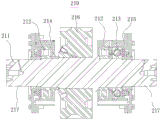
FIG. 4 is a cross-sectional view of an intermediate gearbox for a hybrid vehicle;
FIG. 5 is a schematic perspective view of an intermediate gear box for a hybrid vehicle;
FIG. 6 is a schematic structural view of an input shaft assembly of the intermediate gearbox;
FIG. 7 is a schematic structural view of an output shaft assembly of the intermediate gearbox;
FIG. 8 is a schematic diagram of the lubrication system;
fig. 9 is a schematic structural view of the oil interceptor hood.
In the drawings
100-a box body; 101-loading the box body; 102-a middle box body; 103-lower box body; 104-a breathable cap; 105-upper viewing cover; 106-oil separation hood; 107-lower viewing cover one; 108-lower viewing cover two; 109-oil inlet cover; 110-oil mark; 111-motor mount; 112-front mount mounting face; 113-a rear mount mounting face; 114-oil drainage and blockage; 200-a gear change system; 210-an input shaft assembly; 211-input shaft; 212-cylindrical roller bearing one; 213-four-point contact ball bearing; 214-bearing housing one; 215-bearing housing two; 216-input bevel gear; 217-conical surface; 220-an output shaft assembly; 221-an output flange; 222-an output shaft; 223-an oil pump drive gear; 224-bearing housing three; 225-cylindrical roller bearing two; 226-output bevel gear; 230-a lubrication system; 231-a bidirectional gear oil pump; 232-oil pump input gear; 233-oil filter; 234-oil pump mount; 235-oil separator; 236-tubing; 237-a pipe joint; 238-oil channel; 239-an oil pan; 240-magnetic steel.
Detailed Description
In the following, only certain exemplary embodiments are briefly described. As those skilled in the art will recognize, the described embodiments may be modified in various different ways, all without departing from the spirit or scope of the present invention. Accordingly, the drawings and description are to be regarded as illustrative in nature, and not as restrictive.
In the description of the embodiments of the present application, it is to be understood that the terms "central," "longitudinal," "lateral," "length," "width," "thickness," "upper," "lower," "front," "rear," "left," "right," "vertical," "horizontal," "top," "bottom," "inner," "outer," "clockwise," "counterclockwise," "axial," "radial," "circumferential," and the like are used in an orientation or positional relationship indicated in the drawings for convenience in describing the invention and for simplicity in description, and are not intended to indicate or imply that the referenced device or element must have a particular orientation, be constructed and operated in a particular orientation, and are therefore not to be considered limiting.
Furthermore, the terms "first", "second" and "first" are used for descriptive purposes only and are not to be construed as indicating or implying relative importance or implicitly indicating the number of technical features indicated. Thus, a feature defined as "first" or "second" may explicitly or implicitly include one or more of that feature. In the description of the embodiments of the present application, "a plurality" means two or more unless specifically defined otherwise.
The following disclosure provides many different embodiments or examples for implementing different features of the invention. To simplify the disclosure of the present invention, the components and arrangements of specific examples are described below. Of course, they are merely examples and are not intended to limit the present invention. Moreover, embodiments of the present application may repeat reference numerals or letters in the various examples, such repetition is for the purpose of simplicity and clarity and does not in itself dictate a relationship between the various embodiments and/or configurations discussed.
Embodiments of the present application will be described in detail below with reference to the accompanying drawings.
The invention provides an intermediate gear box for a hybrid electric vehicle, which comprises: a housing 100, a gear change system 200, and a lubrication system 230.
1-5, a housing 100, said housing 100 housing a gear change system 200 and a lubrication system 230; the box body 100 comprises an upper box body 101, a middle box body 102 and a lower box body 103; the upper box body 101 and the middle box body 102, and the middle box body 102 and the lower box body 103 are assembled and connected into a whole through bolts, and lubricating oil can be stored at the bottom of the lower box body 103. The middle box body 102 is provided with two traction motor mounting seats 111, the two motor mounting seats 111 are symmetrically distributed along the central axis of the gear box, and the two traction motors can be directly mounted on the gear box, so that the problem that the coaxiality of a motor output shaft and a gear box input shaft is difficult to guarantee due to different positioning references when the motors are mounted on a frame is solved. And the motor can be directly assembled on the gear box before the gear box is assembled, so that the assembly difficulty is greatly reduced. Two front mounting seat mounting surfaces 112 and two rear mounting seat mounting surfaces 113 are arranged on two side surfaces of the middle box body 102. The two front mounting seat holes and the two rear mounting seat holes are symmetrically distributed along the central axis of the gear box and are used for mounting the front mounting seat and the rear mounting seat, and the front mounting seat and the rear mounting seat are transitional connecting parts between the front mounting seat and a locomotive frame and are parts which are designed and used along for the original internal combustion locomotive.
1-7, a gear change system 200, said gear change system 200 including an input shaft assembly 210 and an output shaft assembly 220; the gear speed change system 200 is used for transmitting the rotating speed and the torque of a driving device (a traction motor) to the speed reduction and torque increase effect through internal gear transmission and transmitting the rotating speed and the torque to an actuating element (a locomotive two-position axle gear box).
The input shaft assembly 210 and the output shaft assembly 220 are arranged in parallel and horizontally, the input shaft assembly 210 is positioned between the box separating surfaces of the upper box body 101 and the middle box body 102, the output shaft assembly 220 is positioned between the box separating surfaces of the middle box body 102 and the lower box body 103, and the input shaft assembly 210 is positioned above the output shaft assembly 220.
The input shaft assembly 210 comprises an input bevel gear 216, the output shaft assembly 220 comprises an output bevel gear 226, the input bevel gear 216 and the output bevel gear 226 are in inner meshing connection in the box body 100, two shaft ends of the input shaft assembly 210 are arranged outside the box body 100, two shaft ends of the input shaft assembly 210 are provided with conical surfaces 217, and the conical surfaces 217 are connected with an elastic coupling through interference fit and further connected with a traction motor; two shaft ends of the output shaft assembly 220 are arranged outside the box body 100, output flanges 221 are arranged at two ends of the output shaft assembly 220, and the output flanges 221 are connected with an input flange of a two-position axle gear box of the locomotive through universal couplings.
A transverse oil passage is arranged right above the input bevel gear 216 and is arranged on the upper box body 101. The output bevel gear 226 is partially arranged below the oil level surface of the lower box body 103, and can rotate to enable the tooth surface to carry lubricating oil during operation, so that meshing lubrication with the input bevel gear 216 is completed. When the input rotation speed of the gear box is low, the excircle linear speed of the output bevel gear 226 is lower than the lowest linear speed requirement required by splash lubrication, and the tooth surface lubrication is insufficient, so that the upper box body 101 is also provided with a transverse oil duct 238 which is communicated with the left oil path and is positioned right above the input bevel gear 216, and the oil duct 238 is provided with a plurality of small holes, so that the lubricating oil can be directly sprayed to the tooth surface of the input bevel gear 216 to achieve the effect of supplementary lubrication.
The input shaft assembly 210 comprises an input shaft 211, a first cylindrical roller bearing 212 and a four-point contact ball bearing 213; the first cylindrical roller bearing 212 and the four-point contact ball bearing 213 are arranged in a second bearing sleeve 215, and the first cylindrical roller bearing 212 is arranged in the first bearing sleeve 214; the input shaft assembly 210 is connected with the box body 100 through a first bearing sleeve 214 and a second bearing sleeve 215.
The output shaft assembly 220 comprises an output shaft 212, a first cylindrical roller bearing 212, an oil pump driving gear 223, a second cylindrical roller bearing 225 and a four-point contact ball bearing 213; the second cylindrical roller bearing 225 is arranged in a third bearing sleeve 224, and the first cylindrical roller bearing 212 and the four-point contact ball bearing 213 are respectively arranged in the first bearing sleeve 214; the output shaft assembly 220 is connected with the box body 100 through a first bearing sleeve 214 and a third bearing sleeve 224. The left end and the right end of the output shaft assembly 220 are connected with the box body 100 through the first bearing sleeve 214, and the middle of the output shaft assembly is connected with the third bearing sleeve 224, and the diameter of the output bevel gear 226 is larger than that of the input bevel gear 216, so that the effects of reducing the rotating speed and increasing the torque can be achieved in the gear meshing process. Because all parts of the oil pump input gear 232 are higher than the oil level surface of the lower box 103 and can not be subjected to splash lubrication, a small hole is also formed in the oil passage of the middle box 102 of the left oil passage and is right above the oil pump driving gear 223, and lubricating oil can be directly sprayed to the tooth surface to achieve the lubricating effect on the oil pump driving gear 223 and the oil pump input gear 232. All parts of the gearbox are fully lubricated, and meanwhile, the lubricating oil takes away heat generated by friction of the parts and finally flows back to the bottom of the box body 100 under the action of gravity. The bidirectional gear oil pump 231 and gravity enable lubricating oil to obtain power which flows in the gear box in a rapid circulating mode, the output bevel gear 226 stirs and splashes the lubricating oil to the inner wall of the box body 100, and therefore heat dissipation performance of the gear box is improved. The whole lubricating system can effectively reduce the oil temperature, thereby reducing the temperature rise of the gear box, enabling the gear box to work normally and continuously, reducing the maintenance times and prolonging the service life. The input shaft assembly 210 is used for receiving the torque and the rotating speed of the traction motor, transmitting the torque and the rotating speed to the output shaft assembly 220 through gears, and finally transmitting the torque and the rotating speed to the locomotive two-position axle gearbox through the output shaft assembly 220.
1-8, a lubrication system 230, the lubrication system 230 providing lubrication to the gearbox; the lubricating oil is used for lubricating and cooling each rotating part of the gearbox.
The lubricating system 230 comprises a bidirectional gear oil pump 231, an oil pump input gear 232, an oil filter 233, an oil pump seat 234, an oil separator 235, an oil pipe 236, a pipe joint 237, an oil passage 238, magnetic steel 240 and an oil pan 239; the input shaft assembly 210 and the output shaft assembly 220 are provided with a first bearing sleeve 214, a second bearing sleeve 215 and a third bearing sleeve 224, the oil passage 238 is arranged on the box body 100, and the bidirectional gear oil pump 231 is communicated with oil inlets of the input shaft assembly 210, the first bearing sleeve 214, the second bearing sleeve 215 and the third bearing sleeve 224 through an oil separator 235, an oil pipe 236, a pipe joint 237 and the oil passage 238.
The bidirectional gear oil pump 231 pumps the lubricating oil at the bottom of the box body 100 to the oil separator 235, the lubricating oil is divided in the oil separator 235 to form a left oil path and a right oil path, and the left oil path and the right oil path sequentially pass through the oil pipe 236, the pipe joint 237 and the oil path 238 on the box body 100 to reach the bearing sleeves of the input shaft assembly 210 and the output shaft assembly 220, and are sprayed out from oil outlets after passing through oil holes on the bearing sleeves, so that the lubricating effect on bearings in the bearing sleeves is achieved.
An oil filter 233 in the lubrication system 230 is mounted on an oil pump base 234; the oil pump input gear 232 is mounted on the bidirectional gear oil pump 231; the oil pump seat 234 and the bidirectional gear oil pump 231 are arranged on an oil pan 239; the oil pan 239 is mounted on the lower box body 103 and is arranged at the bottom of the lower box body 103, and the bottom of the oil pan 239 is provided with an oil drain plug 114. The oil filter 233 can filter and purify lubricating oil, and the magnetic steel 240 can adsorb iron chips in the lubricating oil, so that pollutants in the lubricating oil are reduced, and the service life of bearings, gears and the like in the gear box is prolonged. The oil filter 233, the bidirectional gear oil pump 231, the oil pump seat 234 and the magnetic steel 240 are directly or indirectly mounted on the oil pan 239, the oil pan 239 is mounted at the bottom of the lower box 103 and can be taken out from the bottom of the lower box 103 in an outward dismounting manner, so that when the lubricating system is maintained (such as scrap iron on the magnetic steel 240 and filter on the oil filter 233 are removed), the gear box does not need to be completely dismounted and disassembled, and the oil pan 239 is taken out from the bottom of the lower box 103 in an outward dismounting manner, so that the maintenance efficiency is greatly improved. When the lubricant needs to be replaced, the oil drain plug 114 at the bottom of the oil pan 239 is located at the lowest point of the tank volume, so that the lubricant in the gear box can be fully drained.
In the present embodiment, the input helical gear 216 and the output helical gear 226 are standard involute helical gears, the oil pump drive gear 223 and the oil pump input gear 232 are standard involute helical gears, and the first cylindrical roller bearing 212, the second cylindrical roller bearing 225, and the four-point contact ball bearing 213 are standard bearings, so that the interchangeability is high, and the maintenance cost is low.
As shown in fig. 1-9, the top of the upper box 101 is provided with an upper viewing cover 105 and a ventilation cap 104, the left and right side surfaces of the lower box 103 are respectively provided with a first lower viewing cover 107 and a second lower viewing cover 108, the front surface of the lower box 103 is provided with an oil pointer 110 and an oil inlet cover 109, the bottom of the lower box 103 is provided with an oil separation cover 106, and the oil separation cover 106 is arranged below the output helical gear. The upper observation cover 105 of the invention is connected with the upper box body 101 through bolts, and can observe or detect the input bevel gear 216 after being disassembled, and can also check the oil injection condition of the lubrication system at the part. The ventilation cap 104 is a respirator of the gear box, the temperature inside the gear box can change during shutdown and work, so that internal and external pressure difference is caused, the ventilation cap 104 can be used as the respirator to adjust the internal air pressure of the gear box, the internal air pressure is consistent with the external air pressure, and meanwhile, a filter screen capable of filtering air is arranged in the ventilation cap 104 for preventing external pollutants from entering the gear box. The first lower observation cover 107 and the second lower observation cover 108 are connected to the lower case 103 by bolts, and the output helical gear 226, the lubrication system 230, the case 100, the oil separation cover 106, and the like can be observed or detected after disassembly. The oil inlet cover 109 is used for oiling the gearbox after being detached. The oil pointer 110 is used to ensure a sufficient and proper amount of lubricating oil when refueling. The oil separation cover 106 separates the part of the output bevel gear 226 below the oil level surface of the lower box body 103 to form a single volume space, and a plurality of small holes are arranged on the oil separation cover 106, so that the lubricating oil in the box body 100 can slowly flow into the oil separation cover 106. Because the lubricating oil in the oil separating cover 106 is relatively independent and limited in flow, the oil separating cover 106 can prevent the lubricating oil from being stirred too violently by the output bevel gear 226 when the gearbox runs at a high speed, so that the oil temperature is increased, and the temperature of the gearbox is increased too high.
Gearbox lubrication and heat dissipation principle: the bidirectional gear oil pump 231 pumps the lubricating oil at the bottom of the box body 100 to the oil separator 235, the lubricating oil is divided in the oil separator 235 to form a left oil path and a right oil path, and the left oil path and the right oil path sequentially pass through the oil pipe 236, the pipe joint 237 and the oil path 238 on the box body 100 to reach the bearing sleeves of the input shaft assembly 210 and the output shaft assembly 220, and are sprayed out from oil outlets after passing through oil holes on the bearing sleeves, so that the lubricating effect on bearings in the bearing sleeves is achieved. The output bevel gear 226 is partially arranged below the oil level surface of the lower box body 103, and can rotate to enable the tooth surface to carry lubricating oil during operation, so that meshing lubrication with the input bevel gear 216 is completed. When the rotating speed of the input shaft 211 of the gear box is low, the excircle linear speed of the output bevel gear 226 is lower than the lowest linear speed requirement required by splash lubrication, and the tooth surface lubrication is insufficient, so that the upper box body 101 is also provided with a transverse oil duct 238 which is communicated with the left oil path and is positioned right above the input bevel gear 216, and the oil duct 238 is provided with a plurality of small holes, so that the lubricating oil can be directly sprayed to the tooth surface of the input bevel gear 216 to achieve the effect of supplementary lubrication. In addition, since all parts of the oil pump input gear 232 are higher than the oil level surface of the lower box 103, no splash lubrication can be performed, so that a small hole is also formed in the oil passage 238 of the middle box 102 of the left oil passage, and the small hole is right above the oil pump drive gear 223, so that the lubricating oil can be directly sprayed to the tooth surface to achieve the lubricating effect on the oil pump drive gear 223 and the oil pump input gear 232. All parts of the gearbox are fully lubricated, and meanwhile, the lubricating oil takes away heat generated by friction of the parts and finally flows back to the bottom of the box body 100 under the action of gravity. The bidirectional gear oil pump 231 and gravity enable lubricating oil to obtain power which flows in the gear box in a rapid circulating mode, the output bevel gear 226 stirs and splashes the lubricating oil to the inner wall of the box body 100, and therefore heat dissipation performance of the gear box is improved. The whole lubricating system 230 can effectively reduce the oil temperature, so that the temperature rise of the gearbox is reduced, the gearbox can normally and continuously work, the maintenance frequency can be reduced, and the service life can be prolonged.
The above description is only for the specific embodiments of the present invention, but the scope of the present invention is not limited thereto, and any person skilled in the art can easily conceive of the changes or substitutions within the technical scope of the present invention, and all the changes or substitutions should be covered within the scope of the present invention.
Claims (10)
1. The utility model provides an intermediate gear box for hybrid electric vehicle which characterized in that: the method comprises the following steps:
a case (100), said case (100) housing a gear change system (200) and a lubrication system (230); the box body (100) comprises an upper box body (101), a middle box body (102) and a lower box body (103);
the gear change system (200) includes an input shaft assembly (210) and an output shaft assembly (220);
the lubrication system (230) providing lubrication to the gearbox;
the lubricating system (230) comprises a bidirectional gear oil pump (231), an oil pump input gear (232), an oil filter (233), an oil separator (235), an oil pipe (236), a pipe joint (237) and an oil channel (238); the oil inlet of the two-way gear oil pump (231) is communicated with the oil inlet of the first bearing sleeve (214) and the second bearing sleeve (215) on the input shaft assembly (210) and the oil inlet of the first bearing sleeve (214) and the second bearing sleeve (215) and the oil inlet of the third bearing sleeve (224) on the output shaft assembly (210) through the oil distributor (235), the oil pipe (236), the pipe joint (237) and the oil duct (238).
2. The intermediate gear box for a hybrid vehicle according to claim 1, wherein: the input shaft assembly (210) and the output shaft assembly (220) are parallel to each other and are horizontally installed, the input shaft assembly (210) is located between box splitting surfaces of the upper box body (101) and the middle box body (102), the output shaft assembly (220) is located between box splitting surfaces of the middle box body (102) and the lower box body (103), and the input shaft assembly (210) is located above the output shaft assembly (220).
3. The intermediate gear box for a hybrid vehicle according to claim 1, wherein: the input shaft assembly (210) comprises an input bevel gear (216), the output shaft assembly (220) comprises an output bevel gear (226), the input bevel gear (216) and the output bevel gear (226) are in inner meshing connection in the box body (100), two shaft ends of the input shaft assembly (210) are arranged outside the box body (100), two shaft ends of the input shaft assembly (210) are provided with conical surfaces (217), an oil channel (238) is arranged on the upper box body (101), and the oil channel (238) is arranged above the input bevel gear (216) and in the transverse direction; two shaft ends of the output shaft assembly (220) are arranged outside the box body (100), and output flanges (221) are arranged at two ends of the output shaft assembly (220).
4. The intermediate gear box for a hybrid vehicle according to claim 1, wherein: two traction motor mounting seats (111) are arranged on the middle box body (102), and two front mounting seat mounting surfaces (112) and two rear mounting seat mounting surfaces (113) are arranged on two side surfaces of the middle box body (102).
5. The intermediate gear box for a hybrid vehicle according to claim 1, wherein: the input shaft assembly (210) is connected with the box body (100) through a first bearing sleeve (214) and a second bearing sleeve (215).
6. The intermediate gear box for a hybrid vehicle according to claim 1, wherein: the left end and the right end of the output shaft assembly (220) are connected with the box body (100) through two bearing sleeves I (214) and the middle of the output shaft assembly is connected with the box body (100) through two bearing sleeves III (224).
7. The intermediate gear box for a hybrid vehicle according to claim 1, wherein: the upper box body (101) and the middle box body (102) as well as the middle box body (102) and the lower box body (103) are assembled and connected into a whole through bolts, and lubricating oil can be stored at the bottom of the lower box body (103).
8. The intermediate gear box for a hybrid vehicle according to claim 1, wherein: the lubricating system (230) comprises an oil pump seat (234), magnetic steel (240) and an oil sump (239), and an oil filter (233) in the lubricating system (230) is arranged on the oil pump seat (234); the oil pump input gear (232) is arranged on the bidirectional gear oil pump (231); the oil pump seat (234) and the bidirectional gear oil pump (231) are arranged on an oil pan (239); the oil pan (239) is mounted on the lower box body (103) and arranged at the bottom of the lower box body (103), and an oil drain plug (114) is arranged at the bottom of the oil pan (239).
9. The intermediate gear box for a hybrid vehicle according to claim 1, wherein: and the bottom of the lower box body (103) is provided with an oil separation cover (106), and the oil separation cover (106) is arranged below the output bevel gear (226) and surrounds the lower half part of the output bevel gear (226).
10. The intermediate gear box for a hybrid vehicle according to claim 9, wherein: the oil separating cover (106) separates the part of the output bevel gear (226) below the oil level surface of the lower box body (103) to form a single space, a plurality of small holes are formed in the oil separating cover (106), and lubricating oil at the bottom of the box body (100) flows into the oil separating cover (106) through the small holes.
Priority Applications (1)
| Application Number | Priority Date | Filing Date | Title |
|---|---|---|---|
| CN202011209796.3A CN112303217A (en) | 2020-11-03 | 2020-11-03 | Intermediate gear box for hybrid electric locomotive |
Applications Claiming Priority (1)
| Application Number | Priority Date | Filing Date | Title |
|---|---|---|---|
| CN202011209796.3A CN112303217A (en) | 2020-11-03 | 2020-11-03 | Intermediate gear box for hybrid electric locomotive |
Publications (1)
| Publication Number | Publication Date |
|---|---|
| CN112303217A true CN112303217A (en) | 2021-02-02 |
Family
ID=74332526
Family Applications (1)
| Application Number | Title | Priority Date | Filing Date |
|---|---|---|---|
| CN202011209796.3A Pending CN112303217A (en) | 2020-11-03 | 2020-11-03 | Intermediate gear box for hybrid electric locomotive |
Country Status (1)
| Country | Link |
|---|---|
| CN (1) | CN112303217A (en) |
Cited By (1)
| Publication number | Priority date | Publication date | Assignee | Title |
|---|---|---|---|---|
| CN114321281A (en) * | 2021-12-31 | 2022-04-12 | 大连华锐重工集团股份有限公司 | Heavy gear box for rolling mill |
-
2020
- 2020-11-03 CN CN202011209796.3A patent/CN112303217A/en active Pending
Cited By (2)
| Publication number | Priority date | Publication date | Assignee | Title |
|---|---|---|---|---|
| CN114321281A (en) * | 2021-12-31 | 2022-04-12 | 大连华锐重工集团股份有限公司 | Heavy gear box for rolling mill |
| CN114321281B (en) * | 2021-12-31 | 2023-07-14 | 大连华锐重工集团股份有限公司 | Heavy gear box for rolling mill |
Similar Documents
| Publication | Publication Date | Title |
|---|---|---|
| US11619297B2 (en) | Oil lubrication mechanism for front bearing of water-cooled motor and motor driving assembly | |
| CN107257179B (en) | Gear box motor integrated structure and pinion box motor integrated driving oil way structure | |
| CN210196418U (en) | Novel heavy multi-gear transmission forced lubrication system | |
| CN103836167B (en) | A kind of dynamic coupling device cooling and lubricating system of hybrid vehicle | |
| CN101539196A (en) | Automatic power type lubricant passage way system for transmission of satellite gears | |
| CN208057908U (en) | Electric drive assembly lubricating system | |
| CN112303217A (en) | Intermediate gear box for hybrid electric locomotive | |
| CN201568560U (en) | Straight toothed planetary transmission device for nuclear power water circulation cooling pumps | |
| CN113669435B (en) | Lubricating and cooling system of hybrid power type driving system and vehicle | |
| CN201262225Y (en) | Circulating system with forced inner lubrication structure | |
| CN213776313U (en) | Intermediate gear box for hybrid electric locomotive | |
| CN209705250U (en) | A kind of water-cooled machine fore bearing oil lubrication mechanism and motor driven assembly | |
| CN109538745A (en) | The connection spline lubricating structure of electric commercial vehicle motor and gearbox | |
| CN213512006U (en) | Guiding type oil delivery mechanism of automobile transmission | |
| CN211449594U (en) | Novel high-power one-shaft power takeoff | |
| CN209414584U (en) | The lubrication system of bridge case integrated gearbox system | |
| CN209557628U (en) | The connection spline lubricating structure of electric commercial vehicle motor and gearbox | |
| CN220396431U (en) | New energy electricity drives system bearing lubrication system | |
| CN112610682A (en) | Active lubricating and cooling system for new energy automobile transmission | |
| CN219841017U (en) | Speed reducer assembly and vehicle | |
| CN214247494U (en) | Integrated oil-cooling series generator system | |
| CN219888693U (en) | Lubricating structure system of new energy rear-drive speed reducer | |
| CN211624165U (en) | Differential mechanism oil baffle disc | |
| CN219493011U (en) | Reduction gear oil baffle, reduction gear and power assembly | |
| CN220539706U (en) | Lubrication system |
Legal Events
| Date | Code | Title | Description |
|---|---|---|---|
| PB01 | Publication | ||
| PB01 | Publication | ||
| SE01 | Entry into force of request for substantive examination | ||
| SE01 | Entry into force of request for substantive examination |