CN112297083A - Fruit halving equipment for industrial production - Google Patents
Fruit halving equipment for industrial production Download PDFInfo
- Publication number
- CN112297083A CN112297083A CN202011137979.9A CN202011137979A CN112297083A CN 112297083 A CN112297083 A CN 112297083A CN 202011137979 A CN202011137979 A CN 202011137979A CN 112297083 A CN112297083 A CN 112297083A
- Authority
- CN
- China
- Prior art keywords
- fixing rod
- rod
- rack
- frame
- fruit
- Prior art date
- Legal status (The legal status is an assumption and is not a legal conclusion. Google has not performed a legal analysis and makes no representation as to the accuracy of the status listed.)
- Withdrawn
Links
Images


Classifications
-
- B—PERFORMING OPERATIONS; TRANSPORTING
- B26—HAND CUTTING TOOLS; CUTTING; SEVERING
- B26D—CUTTING; DETAILS COMMON TO MACHINES FOR PERFORATING, PUNCHING, CUTTING-OUT, STAMPING-OUT OR SEVERING
- B26D1/00—Cutting through work characterised by the nature or movement of the cutting member or particular materials not otherwise provided for; Apparatus or machines therefor; Cutting members therefor
- B26D1/01—Cutting through work characterised by the nature or movement of the cutting member or particular materials not otherwise provided for; Apparatus or machines therefor; Cutting members therefor involving a cutting member which does not travel with the work
- B26D1/04—Cutting through work characterised by the nature or movement of the cutting member or particular materials not otherwise provided for; Apparatus or machines therefor; Cutting members therefor involving a cutting member which does not travel with the work having a linearly-movable cutting member
- B26D1/06—Cutting through work characterised by the nature or movement of the cutting member or particular materials not otherwise provided for; Apparatus or machines therefor; Cutting members therefor involving a cutting member which does not travel with the work having a linearly-movable cutting member wherein the cutting member reciprocates
- B26D1/08—Cutting through work characterised by the nature or movement of the cutting member or particular materials not otherwise provided for; Apparatus or machines therefor; Cutting members therefor involving a cutting member which does not travel with the work having a linearly-movable cutting member wherein the cutting member reciprocates of the guillotine type
-
- B—PERFORMING OPERATIONS; TRANSPORTING
- B26—HAND CUTTING TOOLS; CUTTING; SEVERING
- B26D—CUTTING; DETAILS COMMON TO MACHINES FOR PERFORATING, PUNCHING, CUTTING-OUT, STAMPING-OUT OR SEVERING
- B26D7/00—Details of apparatus for cutting, cutting-out, stamping-out, punching, perforating, or severing by means other than cutting
- B26D7/06—Arrangements for feeding or delivering work of other than sheet, web, or filamentary form
-
- B—PERFORMING OPERATIONS; TRANSPORTING
- B26—HAND CUTTING TOOLS; CUTTING; SEVERING
- B26D—CUTTING; DETAILS COMMON TO MACHINES FOR PERFORATING, PUNCHING, CUTTING-OUT, STAMPING-OUT OR SEVERING
- B26D7/00—Details of apparatus for cutting, cutting-out, stamping-out, punching, perforating, or severing by means other than cutting
- B26D7/27—Means for performing other operations combined with cutting
- B26D7/32—Means for performing other operations combined with cutting for conveying or stacking cut product
-
- B—PERFORMING OPERATIONS; TRANSPORTING
- B26—HAND CUTTING TOOLS; CUTTING; SEVERING
- B26D—CUTTING; DETAILS COMMON TO MACHINES FOR PERFORATING, PUNCHING, CUTTING-OUT, STAMPING-OUT OR SEVERING
- B26D2210/00—Machines or methods used for cutting special materials
- B26D2210/02—Machines or methods used for cutting special materials for cutting food products, e.g. food slicers
Abstract
The invention relates to fruit halving equipment, in particular to fruit halving equipment for industrial production. The invention provides fruit halving equipment for industrial production, which can automatically transport and halve fruits and automatically collect the fruits which are processed. A fruit halving device for industrial production comprises: the supporting rod is provided with a first fixing rod; the first fixing rod is provided with a discharging frame; the first fixing rod is provided with a feeding mechanism; the automatic cutting mechanism is arranged on the blanking mechanism. According to the automatic fruit feeding device, through the design of the feeding mechanism, the purpose of automatic feeding can be realized, fruits do not need to be manually taken and sequentially placed, and the feeding amount of each time can be controlled to be consistent; through the design of automatic cutting mechanism, can realize cutting half to fruit, do not need artifical manual sword of holding to cut fruit, reduced the risk that the workman is accidentally injured by the cutter.
Description
Technical Field
The invention relates to fruit halving equipment, in particular to fruit halving equipment for industrial production.
Background
With the rapid soaring of Chinese economy, the consumption level of Chinese people is stronger and stronger, the middle-end and high-end food manufacturing industry in China is greatly developed, and after long-term development, the specialization degree is higher and higher, and the competitive strength is more and more intense in the food manufacturing industry in China, so that each enterprise needs to improve the production technology thereof, so that the market is competitive, the fruit processing still adopts the way of manually cutting the fruits into halves and then manually collecting the fruits, and the cost of the products of a plurality of companies at present continuously rises, so that the manual mode does not meet the requirement of effectively controlling the production cost.
In view of the above problems, it is highly desirable to design a fruit halving device for industrial production, which can automatically transport and halve fruits and automatically collect processed fruits.
Disclosure of Invention
In order to overcome the defect of low production efficiency of manual fruit halving, the invention has the technical problems that: the fruit halving equipment for industrial production is capable of automatically transporting fruits to halve and automatically collecting the fruits which are processed.
The technical implementation scheme of the invention is as follows: a fruit halving device for industrial production comprises: the supporting rod is provided with a first fixing rod; the first fixing rod is provided with a discharging frame; the first fixing rod is provided with a feeding mechanism; the automatic cutting mechanism is arranged on the blanking mechanism.
Further, unloading mechanism is including: the first fixing rod is provided with a first positioning rod in a sliding manner; the first positioning rod is provided with a first rack; the first spring is sleeved on the first positioning rod, and two ends of the first spring are respectively connected with the first positioning rod and the first fixing rod; the first fixing rod is provided with a first fixing rod; the motor is arranged on the second fixing rod; the output shaft of the motor is provided with a gear which is meshed with the first rack; the first rack is provided with a material taking rod; the sliding plate is arranged at the bottom in the discharging frame in a sliding mode; and the sliding plate is symmetrically sleeved with second springs, and the second springs are connected with the discharging frame.
Further, the automatic cutting mechanism includes: the material taking rod is internally provided with a lifting inclined block in a sliding manner; the lifting inclined block is sleeved with a third spring, and two ends of the third spring are respectively connected with the lifting inclined block and the material taking rod; the discharging frame is provided with a third fixing rod; the third fixing rod is provided with a connecting frame; the connecting frame is symmetrically provided with fourth fixed rods; the inclined plate is arranged between the bottoms of the two fourth fixing rods; the first triangular block is arranged at the bottom of the material taking rod; the lifting tool is arranged on the connecting frame in a sliding manner; and the fourth spring is symmetrically arranged on the lifting cutter, and the top end of the fourth spring is connected with the connecting frame.
Further, still including the feeding agencies, be equipped with feeding agencies on the connecting frame.
Further, the material taking mechanism comprises: the material taking rod is provided with a second rack; the connecting frame is provided with a fifth fixing rod; the fifth fixed rod is rotatably provided with a first straight gear; the gear fixing rod is arranged on the connecting frame; the gear fixing rod is rotatably provided with a second straight gear; the transmission assembly is wound between the second straight gear and the first straight gear; the lifting frame is arranged on one side of the connecting frame in a sliding manner; the bottom of the lifting frame is symmetrically provided with fifth springs, and the bottom ends of the fifth springs are connected with the connecting frame; the lifting frame is provided with a first rack which is meshed with the first straight gear; a scraper, wherein the lifting frame is provided with the scraper in a rotating way.
Further, still including receiving agencies, be equipped with receiving agencies on the first dead lever.
Further, receiving agencies including: the first fixing rod is provided with a material receiving frame; the connecting frame is provided with a blanking track; the connecting frame is provided with a sixth fixed rod; the sixth fixing rod is provided with a fourth rack; the scraper is provided with a third straight gear which is meshed with the fourth rack; and the scraper is sleeved with the torsion spring, and two ends of the torsion spring are respectively connected with the scraper and the third straight gear.
The invention has the following advantages: 1. according to the automatic fruit feeding device, through the design of the feeding mechanism, the purpose of automatic feeding can be realized, fruits do not need to be manually taken and sequentially placed, and the feeding amount of each time can be controlled to be consistent;
2. through the design of the automatic cutting mechanism, the fruit can be cut into halves, the fruit is not required to be cut by holding a knife manually, and the risk that workers are accidentally injured by the knife is reduced;
3. through receiving agencies's design, can realize the automatic purpose of collecting to the fruit that finishes processing, do not need artifical manual going to collect for the process velocity to fruit, the subsequent encapsulation of the fruit of being convenient for.
Drawings
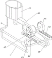
Fig. 1 is a schematic perspective view of the present invention.
Fig. 2 is a schematic perspective view of a first part of the blanking mechanism of the present invention.
Fig. 3 is a schematic perspective view of a second part of the blanking mechanism of the present invention.
Fig. 4 is a schematic perspective view of a first part of the automatic cutting mechanism of the present invention.
Fig. 5 is a schematic perspective view of a second part of the automatic cutting mechanism of the present invention.
Fig. 6 is a schematic perspective view of a first part of a material taking mechanism according to the present invention.
Fig. 7 is a schematic perspective view of a second part of the material taking mechanism of the present invention.
Fig. 8 is a schematic perspective view of a first part of the receiving mechanism of the present invention.
Fig. 9 is a schematic perspective view of a second part of the receiving mechanism of the present invention.
In the above drawings: 1: support rod, 2: first fixed link, 3: a material placing frame, 4: unloading mechanism, 41: first positioning rod, 42: first rack, 43: second fixing lever, 44: motor, 45: missing gear, 46: material taking rod, 47: first spring, 48: sliding plate, 49: second spring, 5: automatic cutting mechanism, 51: third fixing lever, 52: connection frame, 53: lifting inclined block, 54: third spring, 55: fourth fixing bar, 56: diagonal plate, 57: first triangle block, 58: lifting and lowering cutter, 59: fourth spring, 6: material taking mechanism, 61: second rack, 62: fifth fixing lever, 63: first straight gear, 64: lifting frame, 65: fifth spring, 606: gear fixing lever, 66: second spur gear, 67: transmission assembly, 68: third rack, 69: scraper, 7: receiving agencies, 71: material receiving frame, 72: blanking track, 73: sixth fixing lever, 74: third spur gear, 75: fourth rack, 76: a torsion spring.
Detailed Description
The technical solutions in the embodiments of the present invention will be clearly and completely described below with reference to the drawings in the embodiments of the present invention, and it is obvious that the described embodiments are only a part of the embodiments of the present invention, and not all of the embodiments. All other embodiments, which can be derived by a person skilled in the art from the embodiments given herein without making any creative effort, shall fall within the protection scope of the present invention.
Example 1
The utility model provides a fruit is cut half equipment for industrial production, as shown in figure 1, including bracing piece 1, first dead lever 2, blowing frame 3, unloading mechanism 4 and automatic cutting mechanism 5, be equipped with first dead lever 2 on the bracing piece 1, be equipped with blowing frame 3 on the first dead lever 2, be equipped with unloading mechanism 4 on the first dead lever 2, be equipped with automatic cutting mechanism 5 on the unloading mechanism 4.
Firstly, fruit to be cut into halves is placed in the material placing frame 3, then the blanking mechanism 4 is started, the operation of the blanking mechanism 4 drives the operation of the automatic cutting mechanism 5, the fruit half-cutting processing can be realized, after the processing is finished, the blanking mechanism 4 is closed, the blanking mechanism 4 stops operating, so that the automatic cutting mechanism 5 stops operating, if the fruit is required to be cut into halves again, the steps are repeated.
Example 2
On the basis of embodiment 1, as shown in fig. 2, 3, 4 and 5, the blanking mechanism 4 includes a first positioning rod 41, a first rack 42, a second fixing rod 43, a motor 44, a gear-lacking wheel 45, a material-taking rod 46, a first spring 47, a sliding plate 48 and a second spring 49, the first positioning rod 41 is slidably disposed on the right side of the first fixing rod 2, the first rack 42 is disposed on the first positioning rod 41, the first spring 47 is sleeved on the first positioning rod 41, two ends of the first spring 47 are respectively connected with the first fixing rod 2 and the first positioning rod 41, the second fixing rod 43 is disposed on the front side of the first fixing rod 2, the motor 44 is mounted on the second fixing rod 43, the gear-lacking wheel 45 is disposed on an output shaft of the motor 44, the gear-lacking wheel 45 is engaged with the first rack 42, the material-taking rod 46 is disposed on the left side of the first rack 42, the sliding plate 48 is slidably disposed on the bottom of the material-placing frame 3, the second spring 49 is symmetrically sleeved on the sliding, the left side of the second spring 49 is connected with the emptying frame 3.
After the fruit is placed, the motor 44 is started, the output shaft of the motor 44 rotates to drive the gear lacking 45 to rotate, when the gear lacking 45 is meshed with the first rack 42, the first rack 42 is driven to move leftwards, so that the first positioning rod 41 and the material taking rod 46 are driven to move leftwards, the first spring 47 is in a stretching state, when the material taking rod 46 moves leftwards, the sliding plate 48 is driven to move leftwards, the second spring 49 is in a compressing state, the fruit in the material placing frame 3 falls onto the material taking rod 46, when the gear lacking 45 is not meshed with the first rack 42 any more, the first spring 47 is reset from the stretching state, the first rack 42 is driven to move rightwards, so that the first positioning rod 41 and the material taking rod 46 are driven to move rightwards, when the material taking rod 46 moves rightwards, the second spring 49 is reset from the compressing state, the sliding plate 48 is driven, the fruit in the material placing frame 3 does not fall onto the material taking rod 46 any more, the automatic blanking device can achieve the purpose of automatic blanking, fruits do not need to be manually and sequentially placed, and the blanking amount of each time can be controlled to be consistent.
The automatic cutting mechanism 5 comprises a third fixed rod 51, a connecting frame 52, a lifting inclined block 53, a third spring 54, a fourth fixed rod 55, an inclined plate 56, a first triangular block 57, a lifting cutter 58 and a fourth spring 59, the material taking rod 46 is internally provided with a lifting inclined block 53 in a sliding manner, the lifting inclined block 53 is sleeved with a third spring 54, two ends of the third spring 54 are respectively connected with the lifting inclined block 53 and the material taking rod 46, the right side of the material taking frame 3 is provided with a third fixing rod 51, the third fixing rod 51 is provided with a connecting frame 52, the connecting frame 52 is symmetrically provided with fourth fixing rods 55 in the front and back direction, an inclined plate 56 is arranged between the bottoms of the two fourth fixing rods 55, the bottom of the material taking rod 46 is provided with a first triangular block 57, a lifting cutter 58 is slidably arranged on the connecting frame 52, the lifting cutter 58 is symmetrically provided with fourth springs 59 in the front and back direction, and two ends of each fourth spring 59 are respectively connected with the lifting cutter 58 and the connecting.
When the material taking rod 46 moves rightwards, the lifting inclined block 53 and the first triangular block 57 are driven to move rightwards, after the lifting inclined block 53 is contacted with the inclined plate 56, the lifting inclined block 53 moves upwards, the third spring 54 is in a compressed state, fruits on the lifting inclined block 53 can move upwards, subsequent cutting is facilitated, after the first triangular block 57 is contacted with the lifting cutter 58, the lifting cutter 58 is driven to move upwards, the fourth spring 59 is in a compressed state, the fruits move rightwards continuously along with the first triangular block 57, and after the first triangular block 57 is not contacted with the lifting cutter 58 any more, the fourth spring 59 is reset from the compressed state, so that the lifting cutter 58 is driven to move downwards, and the operation is repeated, half-cutting of the fruits can be realized, manual operation for cutting the fruits is not needed, and the risk of mistakenly injuring workers by the cutters is reduced.
Example 3
Based on the embodiment 2, as shown in fig. 6, 7, 8 and 9, the present invention further includes a material taking mechanism 6, the connecting frame 52 is provided with the material taking mechanism 6, the material taking mechanism 6 includes a second rack 61, a fifth fixing rod 62, a first straight gear 63, a lifting frame 64, a fifth spring 65, a second straight gear 66, a gear fixing rod 606, a transmission assembly 67, a third rack 68 and a scraper 69, the material taking rod 46 is provided with the second rack 61, the connecting frame 52 is provided with the fifth fixing rod 62 at the front side, the fifth fixing rod 62 is provided with the first straight gear 63 in a rotating manner, the right side of the connecting frame 52 is provided with the gear fixing rod 606, the gear fixing rod 606 is provided with the second straight gear 66 in a rotating manner, the transmission assembly 67 is wound between the second straight gear 66 and the first straight gear 63, the right side of the connecting frame 52 is provided with the lifting frame 64 in a sliding manner, the bottom of the lifting frame 64 is provided, the bottom end of the fifth spring 65 is connected with the connecting frame 52, the front side of the lifting frame 64 is provided with a third rack 68, the third rack 68 is meshed with the first straight gear 63, and the lifting frame 64 is rotatably provided with a scraper 69.
When the material taking rod 46 moves rightwards, the second rack 61 is driven to move rightwards, after the second rack 61 is meshed with the second straight gear 66, the second straight gear 66 is driven to rotate, the first straight gear 63 is driven to rotate through the transmission assembly 67, the third rack 68 is driven to move downwards due to the meshing of the first straight gear 63 and the third rack 68, the lifting frame 64 and the scraper 69 are driven to move downwards, the fifth spring 65 is in a compressed state, when the material taking rod 46 moves leftwards, fruits processed on the material taking rod 46 are moved onto the scraper 69, the fruits on the material taking rod 46 can be automatically taken down, after the second rack 61 is not meshed with the second straight gear 66 any more, the fifth spring 65 is reset from the compressed state, the lifting frame 64, the scraper 69 and the third rack 68 are driven to move upwards and reset, because the first straight gear 63 is meshed with the third rack 68, therefore, the first straight gear 63 is driven to rotate reversely, the second straight gear 66 is driven to rotate reversely through the transmission assembly 67 to reset, and if the fruit on the material taking rod 46 needs to be taken out again, the steps are repeated.
The material receiving mechanism 7 is further included, the material receiving mechanism 7 is arranged on the first fixing rod 2, the material receiving mechanism 7 comprises a material receiving frame 71, a blanking track 72, a sixth fixing rod 73, a third straight gear 74, a fourth rack 75 and a torsion spring 76, the material receiving frame 71 is arranged on the first fixing rod 2, the blanking track 72 is arranged on the connecting frame 52, the sixth fixing rod 73 is arranged on the rear side of the connecting frame 52, the fourth rack 75 is arranged on the sixth fixing rod 73, the third straight gear 74 is arranged on the rear side of the scraper 69 and meshed with the fourth rack 75, the torsion spring 76 is sleeved on the rear side of the scraper 69, and two ends of the torsion spring 76 are respectively connected with the scraper 69 and the third straight gear 74.
When the scraper 69 moves downwards, the third straight gear 74 is driven to move downwards, and because the third straight gear 74 is meshed with the fourth rack 75, the third straight gear 74 is driven to rotate, the torsion spring 76 deforms, so that the fruits on the scraper 69 can be poured onto the blanking track 72 and slide from the blanking track 72 into the material receiving frame 71, the purpose of automatically collecting the processed fruits can be achieved, manual collection is not needed, the processing speed of the fruits is increased, the subsequent packaging of the fruits is facilitated, when the scraper 69 moves upwards, the third straight gear 74 is driven to move upwards, because the third straight gear 74 is meshed with the fourth rack 75, the third straight gear 74 is driven to rotate reversely to reset, the torsion spring 76 is reset through deformation, and if the processed fruits need to be collected again, the steps are repeated.
While the disclosure has been described with respect to a limited number of embodiments, those skilled in the art, having benefit of this disclosure, will appreciate that various other embodiments can be devised which do not depart from the scope of the invention as disclosed herein. Accordingly, the scope of the invention should be limited only by the attached claims.
Claims (7)
1. The utility model provides a fruit cuts half equipment for industrial production which characterized by including:
the supporting rod (1) is provided with a first fixing rod (2);
the first fixing rod (2) is provided with a discharging frame (3);
the blanking mechanism (4) is arranged on the first fixing rod (2);
the automatic cutting mechanism (5) is arranged on the blanking mechanism (4).
2. Fruit halving apparatus for industrial production according to claim 1, wherein the blanking mechanism (4) comprises:
the first positioning rod (41), the first positioning rod (41) is arranged on the first fixing rod (2) in a sliding mode;
the first rack (42) is arranged on the first positioning rod (41);
the first spring (47) is sleeved on the first positioning rod (41), and two ends of the first spring (47) are respectively connected with the first positioning rod (41) and the first fixing rod (2);
the second fixing rod (43), the first fixing rod (2) is provided with the second fixing rod (43);
the motor (44) is mounted on the second fixing rod (43);
a gear (45) is omitted, the output shaft of the motor (44) is provided with the gear (45), and the gear (45) is meshed with the first rack (42);
the material taking rod (46) is arranged on the first rack (42);
the sliding plate (48) is arranged at the bottom in the discharging frame (3) in a sliding manner;
the sliding plate (48) is symmetrically sleeved with the second springs (49), and the second springs (49) are connected with the discharging frame (3).
3. Fruit halving apparatus for industrial production according to claim 2, wherein the automatic cutting means (5) comprises:
the lifting inclined block (53) is arranged in the material taking rod (46) in a sliding manner;
the lifting inclined block (53) is sleeved with the third spring (54), and two ends of the third spring (54) are respectively connected with the lifting inclined block (53) and the material taking rod (46);
the third fixing rod (51) is arranged on the discharging frame (3);
a connecting frame (52), wherein the third fixing rod (51) is provided with the connecting frame (52);
the fourth fixing rod (55), the connecting frame (52) is symmetrically provided with the fourth fixing rod (55);
the inclined plate (56) is arranged between the bottoms of the two fourth fixing rods (55);
the bottom of the material taking rod (46) is provided with a first triangular block (57);
the lifting cutter (58) is arranged on the connecting frame (52) in a sliding manner;
the fourth spring (59) is symmetrically arranged on the lifting cutter (58), and the top end of the fourth spring (59) is connected with the connecting frame (52).
4. An industrial fruit halving apparatus as claimed in claim 3 further comprising a take off mechanism (6), the connecting frame (52) being provided with the take off mechanism (6).
5. An industrial fruit halving apparatus as claimed in claim 4 wherein the take off mechanism (6) comprises:
the material taking rod (46) is provided with a second rack (61);
a fifth fixing rod (62), wherein the connecting frame (52) is provided with the fifth fixing rod (62);
a first straight gear (63) is rotatably arranged on the fifth fixed rod (62);
the gear fixing rod (606) is arranged on the connecting frame (52);
the second straight gear (66) is rotationally arranged on the gear fixing rod (606);
the transmission assembly (67) is wound between the second straight gear (66) and the first straight gear (63);
the lifting frame (64) is arranged on one side of the connecting frame (52) in a sliding way;
the bottom of the lifting frame (64) is symmetrically provided with fifth springs (65), and the bottom ends of the fifth springs (65) are connected with the connecting frame (52);
a third rack (68), wherein the lifting frame (64) is provided with the third rack (68), and the third rack (68) is meshed with the first straight gear (63);
the scraper (69) is arranged in the lifting frame (64) in a rotating way.
6. The fruit halving device for industrial production according to claim 5, further comprising a material receiving mechanism (7), wherein the material receiving mechanism (7) is arranged on the first fixing rod (2).
7. A fruit halving apparatus as claimed in claim 6 wherein the receiving mechanism (7) comprises:
the first fixing rod (2) is provided with a material receiving frame (71);
the blanking track (72) is arranged on the connecting frame (52);
a sixth fixing rod (73), wherein the connecting frame (52) is provided with the sixth fixing rod (73);
a fourth rack (75), wherein the sixth fixing rod (73) is provided with the fourth rack (75);
the scraper (69) is provided with a third straight gear (74), and the third straight gear (74) is meshed with the fourth rack (75);
the scraper (69) is sleeved with the torsion spring (76), and two ends of the torsion spring (76) are respectively connected with the scraper (69) and the third straight gear (74).
Priority Applications (1)
| Application Number | Priority Date | Filing Date | Title |
|---|---|---|---|
| CN202011137979.9A CN112297083A (en) | 2020-10-22 | 2020-10-22 | Fruit halving equipment for industrial production |
Applications Claiming Priority (1)
| Application Number | Priority Date | Filing Date | Title |
|---|---|---|---|
| CN202011137979.9A CN112297083A (en) | 2020-10-22 | 2020-10-22 | Fruit halving equipment for industrial production |
Publications (1)
| Publication Number | Publication Date |
|---|---|
| CN112297083A true CN112297083A (en) | 2021-02-02 |
Family
ID=74328658
Family Applications (1)
| Application Number | Title | Priority Date | Filing Date |
|---|---|---|---|
| CN202011137979.9A Withdrawn CN112297083A (en) | 2020-10-22 | 2020-10-22 | Fruit halving equipment for industrial production |
Country Status (1)
| Country | Link |
|---|---|
| CN (1) | CN112297083A (en) |
Cited By (1)
| Publication number | Priority date | Publication date | Assignee | Title |
|---|---|---|---|---|
| CN113510765A (en) * | 2021-04-15 | 2021-10-19 | 韦流兵 | Automatic traditional Chinese medicine cutting and matching device for anesthesia department |
Citations (5)
| Publication number | Priority date | Publication date | Assignee | Title |
|---|---|---|---|---|
| US6418823B1 (en) * | 1999-05-26 | 2002-07-16 | Tairob Industrial Technology Ltd. | Processing center for three dimensional cutting of food products |
| US20080006131A1 (en) * | 2004-12-08 | 2008-01-10 | Jones Timothy R | Apparatus for Cutting Fruit Into Slices and Dispensing the Slices |
| CN109602030A (en) * | 2018-12-21 | 2019-04-12 | 杭州云物科技有限公司 | A kind of stoning chopper and slicer for preserved fruit production |
| CN110253650A (en) * | 2019-08-05 | 2019-09-20 | 付迪 | A kind of canopy cultivation fruits and vegetables automatic vegetable-cutting equipment |
| CN111789153A (en) * | 2020-07-22 | 2020-10-20 | 何伟娜 | Nail and snail tail shearing machine |
-
2020
- 2020-10-22 CN CN202011137979.9A patent/CN112297083A/en not_active Withdrawn
Patent Citations (5)
| Publication number | Priority date | Publication date | Assignee | Title |
|---|---|---|---|---|
| US6418823B1 (en) * | 1999-05-26 | 2002-07-16 | Tairob Industrial Technology Ltd. | Processing center for three dimensional cutting of food products |
| US20080006131A1 (en) * | 2004-12-08 | 2008-01-10 | Jones Timothy R | Apparatus for Cutting Fruit Into Slices and Dispensing the Slices |
| CN109602030A (en) * | 2018-12-21 | 2019-04-12 | 杭州云物科技有限公司 | A kind of stoning chopper and slicer for preserved fruit production |
| CN110253650A (en) * | 2019-08-05 | 2019-09-20 | 付迪 | A kind of canopy cultivation fruits and vegetables automatic vegetable-cutting equipment |
| CN111789153A (en) * | 2020-07-22 | 2020-10-20 | 何伟娜 | Nail and snail tail shearing machine |
Cited By (1)
| Publication number | Priority date | Publication date | Assignee | Title |
|---|---|---|---|---|
| CN113510765A (en) * | 2021-04-15 | 2021-10-19 | 韦流兵 | Automatic traditional Chinese medicine cutting and matching device for anesthesia department |
Similar Documents
| Publication | Publication Date | Title |
|---|---|---|
| CN111498195A (en) | Vermicelli cutting and packaging device for food processing | |
| CN112549207B (en) | Equipment capable of cutting wood boards in batches | |
| CN112450242A (en) | Equipment is used in plastic envelope cake production | |
| CN113057193A (en) | Dumpling wrapper forming and cutting equipment for food processing | |
| CN112297083A (en) | Fruit halving equipment for industrial production | |
| CN113352368B (en) | Rapeseed collecting equipment for agricultural production | |
| CN113021448B (en) | Automatic citrus peeling equipment in batches | |
| CN112140199B (en) | Even dicing device of candy for food shop | |
| CN111251339B (en) | Pulp slitting device | |
| CN216753406U (en) | Pastry is face skin shearing mechanism for production | |
| CN113146703B (en) | Rice cake slice canning packing apparatus for food processing | |
| CN214976984U (en) | Stainless steel edge wrapping device for manufacturing show window door | |
| CN112720587B (en) | Rectangular soap processing cutting device | |
| CN113148356B (en) | Cotton mold film removing machine | |
| CN112369442A (en) | Food production is with flattening device | |
| CN212497930U (en) | Efficient chinese-medicinal material section device | |
| CN113246195A (en) | Automatic slitting device for industrial paper cases | |
| CN208759723U (en) | A kind of taro automatic strip-cutting machine | |
| CN112740926A (en) | Be used for industrial flower tail cutting equipment | |
| CN112544994A (en) | Automatic red date seed removing equipment for agricultural product processing | |
| CN112515192A (en) | Peeling equipment is used in dried persimmon production | |
| CN112140155A (en) | Reciprocating type sweet potato vermicelli machine | |
| CN113796400B (en) | Production equipment for children's complementary food cartoon noodles | |
| CN205602633U (en) | Walnut is walnut -meat conveyor that cuts into slices for oil press | |
| CN218837961U (en) | Medicine cutting machine |
Legal Events
| Date | Code | Title | Description |
|---|---|---|---|
| PB01 | Publication | ||
| PB01 | Publication | ||
| SE01 | Entry into force of request for substantive examination | ||
| SE01 | Entry into force of request for substantive examination | ||
| WW01 | Invention patent application withdrawn after publication | ||
| WW01 | Invention patent application withdrawn after publication |
Application publication date: 20210202 |