CN112281287B - Equipment for absorbing and treating textile dust of textile machine - Google Patents
Equipment for absorbing and treating textile dust of textile machine Download PDFInfo
- Publication number
- CN112281287B CN112281287B CN202011214062.4A CN202011214062A CN112281287B CN 112281287 B CN112281287 B CN 112281287B CN 202011214062 A CN202011214062 A CN 202011214062A CN 112281287 B CN112281287 B CN 112281287B
- Authority
- CN
- China
- Prior art keywords
- cavity
- belt
- shaft
- belt wheel
- end wall
- Prior art date
- Legal status (The legal status is an assumption and is not a legal conclusion. Google has not performed a legal analysis and makes no representation as to the accuracy of the status listed.)
- Active
Links
Images


Classifications
-
- D—TEXTILES; PAPER
- D03—WEAVING
- D03J—AUXILIARY WEAVING APPARATUS; WEAVERS' TOOLS; SHUTTLES
- D03J1/00—Auxiliary apparatus combined with or associated with looms
- D03J1/002—Climatic conditioning or removing lint or dust
-
- B—PERFORMING OPERATIONS; TRANSPORTING
- B01—PHYSICAL OR CHEMICAL PROCESSES OR APPARATUS IN GENERAL
- B01D—SEPARATION
- B01D47/00—Separating dispersed particles from gases, air or vapours by liquid as separating agent
- B01D47/06—Spray cleaning
-
- D—TEXTILES; PAPER
- D04—BRAIDING; LACE-MAKING; KNITTING; TRIMMINGS; NON-WOVEN FABRICS
- D04B—KNITTING
- D04B35/00—Details of, or auxiliary devices incorporated in, knitting machines, not otherwise provided for
- D04B35/32—Devices for removing lint or fluff
-
- D—TEXTILES; PAPER
- D06—TREATMENT OF TEXTILES OR THE LIKE; LAUNDERING; FLEXIBLE MATERIALS NOT OTHERWISE PROVIDED FOR
- D06G—MECHANICAL OR PRESSURE CLEANING OF CARPETS, RUGS, SACKS, HIDES, OR OTHER SKIN OR TEXTILE ARTICLES OR FABRICS; TURNING INSIDE-OUT FLEXIBLE TUBULAR OR OTHER HOLLOW ARTICLES
- D06G1/00—Beating, brushing, or otherwise mechanically cleaning or pressure cleaning carpets, rugs, sacks, hides, or other skin or textile articles or fabrics
-
- F—MECHANICAL ENGINEERING; LIGHTING; HEATING; WEAPONS; BLASTING
- F16—ENGINEERING ELEMENTS AND UNITS; GENERAL MEASURES FOR PRODUCING AND MAINTAINING EFFECTIVE FUNCTIONING OF MACHINES OR INSTALLATIONS; THERMAL INSULATION IN GENERAL
- F16H—GEARING
- F16H37/00—Combinations of mechanical gearings, not provided for in groups F16H1/00 - F16H35/00
- F16H37/12—Gearings comprising primarily toothed or friction gearing, links or levers, and cams, or members of at least two of these types
Abstract
The invention discloses equipment for absorbing and treating textile dust of a textile machine, which comprises a box body and a first cavity fixedly arranged in the box body, wherein a driving shaft is rotatably arranged on the upper side end wall of the first cavity, the driving shaft is in power connection with a main shaft of a motor, the motor is fixedly arranged on the upper side end wall of the first cavity, a first belt wheel is fixedly arranged on the outer surface of the driving shaft, and the first belt wheel is in connection transmission with a second belt wheel through a first transmission belt; the invention can realize the absorption of textile dust, can realize the collection treatment of the absorbed textile dust, can utilize the water outlet nozzle to absorb water for the textile dust, can realize the collection treatment of the textile dust by using the weight, can realize the removal of the hair balls on the surface of the textile cloth, can realize the cleaning treatment of the hair ball removing cylinder, and can realize the control of each motion process by using the clutch between the shafts.
Description
Technical Field
The invention relates to the field of textile, in particular to a device for absorbing and treating textile dust of a textile machine.
Background
The textile origin is a general name taken from spinning and weaving, but with the continuous development and perfection of a textile knowledge system and a subject system, particularly after non-woven textile materials and three-dimensional compound weaving and other technologies are produced, the textile is not only produced by traditional hand spinning and weaving, but also produced by non-woven fabric technology, modern three-dimensional weaving technology, modern electrostatic nano-web forming technology and the like, and is used for clothing, industry and decoration. Modern spinning therefore refers to a technique for the multi-scale structural processing of fibers or fiber assemblies. Ancient Chinese weaving and printing technology has a very long history, and ancient people have understood local materials as early as the original society period in order to adapt to climate change, utilize natural resources as raw materials for weaving and printing and dyeing and manufacture simple manual weaving tools. Clothing, airbags and curtain carpets in daily life are products of textile and printing technologies.
Present weaving equipment can produce a large amount of weaving dirt at the in-process of weaving, and weaving dirt can cause harm to staff's healthy, and present equipment of detaching to weaving dirt can only carry out a simple absorption to weaving dirt, can not handle the weaving dirt after absorbing, can not realize handling the pompon on weaving cloth surface, therefore needs to set up an equipment that is used for weaving machine weaving dirt to absorb the processing and improves above-mentioned problem.
Disclosure of Invention
The invention aims to provide a device for absorbing and treating textile dust of a textile machine, which can overcome the defects of the prior art, thereby improving the practicability of the device.
The technical scheme adopted by the invention for solving the technical problems is as follows: the invention relates to equipment for absorbing and treating textile dust of a textile machine, which comprises a box body and a first cavity fixedly arranged in the box body, wherein a driving shaft is rotatably arranged on the upper side end wall of the first cavity, the driving shaft is in power connection with a main shaft of a motor, the motor is fixedly arranged on the upper side end wall of the first cavity, a first belt wheel is fixedly arranged on the outer surface of the driving shaft, the first belt wheel is in connection transmission with a second belt wheel through a first transmission belt, the second belt wheel is fixedly arranged on the outer surface of the upper side tail end of a turntable shaft, the turntable shaft is rotatably arranged on the upper side end wall of a dust removal box in a penetrating way, a dust removal cavity is fixedly arranged in the dust removal box, a dust collection device for absorbing the textile dust in the textile dust generation cavity is arranged on the outer surface of the lower side tail end of the turntable shaft, the textile dust generation cavity is fixedly arranged in the textile dust generation box, the spinning dust generation box is fixedly arranged on the lower side end wall of the first cavity, a spinning cloth outlet is fixedly arranged on the right side end wall of the spinning dust generation cavity, a first bevel gear is fixedly arranged at the lower side tail end of the driving shaft, the first bevel gear and a second bevel gear are in meshing transmission, the second bevel gear is fixedly arranged on the outer surface of the front side tail end of a bevel gear shaft, the bevel gear shaft is rotatably arranged on the rear side end wall of the first cavity, a first transmission device used for transmission between the bevel gear shaft and a collection box mounting plate is arranged on the outer surface of the bevel gear shaft at the rear side of the second bevel gear, a collection box is fixedly arranged on the outer surface of the upper side end wall of the collection box mounting plate, a third belt wheel is fixedly arranged on the outer surface of the bevel gear shaft at the front side of the first transmission device, and the third belt wheel is in connection transmission with a fourth belt wheel through a second transmission belt, the fourth belt wheel is fixedly arranged on the outer surface of a belt wheel shaft, the belt wheel shaft is rotatably arranged on the rear end wall of the first cavity, a second transmission device for transmission between the belt wheel shaft and a hair removing ball roller is arranged on the outer surface of the belt wheel shaft on the rear side of the fourth belt wheel, a cloth collecting barrel is fixedly arranged on the outer surface of the tail end of the front side of the belt wheel shaft on the front side of the belt wheel shaft, woven cloth is connected onto the cloth collecting barrel, the tail end of one side, far away from the cloth collecting barrel, of the woven cloth is connected into a woven cloth outlet through a woven cloth outlet, a rotating rod is rotatably arranged on the rear end wall of the first cavity on the right side of the woven cloth outlet, the woven cloth is arranged on the rotating rod, a cleaning device for removing hair balls on the surface of the woven cloth is arranged between the hair removing ball rollers, and a rotating support rod is rotatably arranged on the rear end wall of the first cavity on the upper side of the cleaning device, the textile cloth is wound on the outer surface of the rotary supporting rod.
Preferably, the dust collector comprises the turntable shaft, a turntable is fixedly arranged on the outer surface of the tail end of the lower side of the turntable shaft, the turntable is far away from the outer fixed circumference array of the end wall of one side of the turntable shaft and is provided with fan blades, exhaust holes are fixedly arranged on the end wall of the upper side of the dust removing cavity on the left side and the right side of the turntable shaft in a symmetrical array manner, a partition plate is fixedly arranged between the end walls of the dust removing cavity on the lower side of the fan blades, a through hole is formed in the partition plate in a fixed array manner, water outlet nozzles are fixedly arranged on the end walls of the left side and the right side of the dust removing cavity on the lower side of the partition plate, baffle plates are rotatably arranged on the end walls of the lower side of the dust removing cavity in a left-right symmetrical manner, baffle plates are fixedly arranged on the outer surfaces of the baffle plates, the baffle plates are connected with the end walls of the dust removing cavity through weight limiting torsion springs, and inlet holes are fixedly arranged on the end walls of the right side of the water outlet nozzles, the textile dust generating device comprises an inlet, a textile dust generating cavity, a connecting hole, a suction pipe, a suction port array and a dust collecting cavity, wherein the inlet is fixedly connected to the inlet, the tail end of one side, far away from the inlet, of the suction pipe is fixedly connected with the connecting hole, the connecting hole is fixedly formed in the upper side end wall of the textile dust generating cavity, a suction cavity is fixedly formed in the upper side end wall of the textile dust generating cavity and is arranged on the lower side of the connecting hole, the suction cavity is communicated with the textile dust generating cavity through a suction port, and the suction port array is fixedly arranged on the upper side end wall of the textile dust generating cavity and is arranged on the lower side of the suction cavity.
Preferably, the first transmission device comprises the bevel gear shaft, the outer fixed surface of the bevel gear shaft at the rear side of the third belt wheel is provided with a fixed block, the fixed block is internally provided with an air pump in a vertically symmetrical manner, the air pump is fixedly connected with a connecting pipe, the connecting pipe is fixedly arranged in the fixed block, the connecting pipe is far away from the fixed connection between the tail end of one side of the air pump and the air bag, the air bag is arranged in an air bag cavity, the fixed vertically symmetrical arrangement of the air bag cavity is arranged on the end wall of one side of the fifth belt wheel, the fifth belt wheel is rotatably arranged on the outer surface of the end part of one side of the bevel gear shaft, the fixed block is far away from the outer surface of the end part of one side of the bevel gear shaft, the fifth belt wheel is connected with the sixth belt wheel through a third transmission belt, the sixth belt wheel is fixedly arranged on the outer surface of the gear shaft, the gear shaft is rotatably arranged on the rear end wall of the first cavity at the lower side of the dust removing box, the terminal fixed surface of front side of gear shaft installs the gear, the meshing transmission between gear and the rack board, rack board slidable mounting is in the upside end wall surface of mount, symmetry fixed mounting is in around the mount on the left side end wall of first cavity, the rack board is left the fixed export that is provided with on the left side end wall of first cavity, the pressure spring switch is installed to rack board upside end wall fixed surface array, the terminal fixedly connected with of pressure spring switch upside the collecting box mounting panel.
Preferably, the second transmission device includes the pulley shaft, a seventh pulley is fixedly mounted on an outer surface of the pulley shaft at a rear side of the fourth pulley, the seventh pulley and an eighth pulley are connected and driven by a fourth transmission belt, the eighth pulley is fixedly mounted on an outer surface of a worm shaft, the worm shaft is rotatably mounted on a rear end wall of the first cavity at a lower side of the rotary support rod, a worm is fixedly mounted on an outer surface of a front end of the worm shaft at a front side of the eighth pulley, the worm and the worm wheel are in meshing transmission, the worm wheel is fixedly mounted on an outer surface of the worm shaft, the worm shaft is rotatably mounted on a worm shaft mounting bracket, the worm shaft mounting bracket is fixedly mounted on a rear end wall of the first cavity, and fourth bevel gears are symmetrically and fixedly mounted on outer surfaces of left and right ends of the worm shaft, the fourth bevel gear and the fourth bevel gear are in meshing transmission, the fourth bevel gear is fixedly installed on the outer surface of a roller shaft, the roller shaft is rotatably installed on the end wall of the rear side of the first cavity, and the outer surface of the tail end of the front side of the roller shaft is fixedly provided with the hair removing ball roller.
Preferably, cleaning device includes the mounting panel, the fixed opening that is provided with on the mounting panel, the opening left and right sides rotate on the mounting panel and install the rotating turret installation axle, the rotating turret is installed to the terminal fixed surface symmetry in both sides around the rotating turret installation axle, the terminal rotation of rotating turret upside installs clean section of thick bamboo installation axle, the fixed surface of clean section of thick bamboo installation axle installs clean section of thick bamboo, fixedly connected with hydraulic stem on the rotating turret, the hydraulic stem is kept away from fixed connection between terminal and the pneumatic cylinder of rotating turret one side, pneumatic cylinder bilateral symmetry fixed mounting is in on the upside end wall of mounting panel.
The invention has the beneficial effects that: the spinning dust collector can absorb spinning dust, can collect and treat the absorbed spinning dust, can absorb water for the spinning dust by using the water outlet nozzle, can collect and treat the spinning dust by using the weight, can remove hair balls on the surface of the spinning cloth, can clean a hair ball removing cylinder, and can control each motion process by using the clutch between shafts.
Drawings
In order to more clearly illustrate the embodiments of the invention or the technical solutions in the prior art, the drawings used in the description of the embodiments or the prior art will be briefly described below, and it is obvious that the drawings in the following description are only some embodiments of the invention, and it is obvious for those skilled in the art that other drawings can be obtained based on these drawings without creative efforts.
The invention is further illustrated with reference to the following figures and examples.
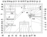
FIG. 1 is a schematic view of the overall structure of an apparatus for dust absorption treatment of textile dust on a textile machine according to the present invention;
FIG. 2 is a schematic view of the structure A-A of FIG. 1;
FIG. 3 is a schematic diagram of B-B of FIG. 1;
FIG. 4 is a schematic diagram of the structure of C-C in FIG. 1;
fig. 5 is an enlarged schematic view of D in fig. 1.
Detailed Description
The invention will now be described in detail with reference to fig. 1-5, wherein for ease of description the orientations described hereinafter are now defined as follows: the up, down, left, right, and front-back directions described below correspond to the up, down, left, right, and front-back directions in the projection relationship of fig. 1 itself.
Combine fig. 1-5 a be used for weaving machine weaving dirt absorption treatment's equipment, include box 11 and box 11 internal fixation be provided with first cavity 12, it has drive shaft 60 to rotate to install on the side end wall of first cavity 12, power connection between the main shaft of drive shaft 60 and motor 28, motor 28 fixed mounting is on the side end wall of first cavity 12, the outer fixed surface of drive shaft 60 installs first band pulley 29, connect the transmission through first driving band 30 between first band pulley 29 and the second band pulley 34, second band pulley 34 fixed mounting is on the terminal surface of carousel axle 35 upside, carousel axle 35 runs through to rotate and installs on the side end wall of dust removal case 37, dust removal case 37 internal fixation is provided with dust removal chamber 38, the terminal surface mounting of downside of carousel axle 35 has the device dust extraction 100 who is used for weaving dirt in the dirt production chamber 52 to absorb weaving dirt, the spinning dust generating chamber 52 is fixedly arranged in the spinning dust generating box 51, the spinning dust generating box 51 is fixedly arranged on the lower end wall of the first cavity 12, the spinning cloth outlet 57 is fixedly arranged on the right end wall of the spinning dust generating chamber 52, the lower end of the driving shaft 60 is fixedly provided with a first bevel gear 59, the first bevel gear 59 is in meshing transmission with a second bevel gear 69, the second bevel gear 69 is fixedly arranged on the outer surface of the front end of a bevel gear shaft 68, the bevel gear shaft 68 is rotatably arranged on the rear end wall of the first cavity 12, the outer surface of the bevel gear shaft 68 on the rear side of the second bevel gear 69 is provided with a first transmission device 101 for transmission between the bevel gear shaft 68 and the collecting box mounting plate 44, and the outer surface of the upper end wall of the collecting box mounting plate 44 is fixedly provided with the collecting box 43, a third belt wheel 61 is fixedly installed on the outer surface of the bevel gear shaft 68 at the front side of the first transmission device 101, the third belt wheel 61 and a fourth belt wheel 71 are connected and transmitted through a second transmission belt 21, the fourth belt wheel 71 is fixedly installed on the outer surface of a belt wheel shaft 74, the belt wheel shaft 74 is rotatably installed on the rear end wall of the first cavity 12, a second transmission device 102 for transmission between the belt wheel shaft 74 and the hair removing ball roller 19 is installed on the outer surface of the belt wheel shaft 74 at the rear side of the fourth belt wheel 71, a cloth collecting cylinder 70 is fixedly installed on the outer surface of the front end of the belt wheel shaft 74 at the front side of the belt wheel shaft 74, a woven cloth 13 is connected to the cloth collecting cylinder 70, the end of one side of the woven cloth 13 far away from the cloth collecting cylinder 70 is connected to the woven cloth outlet 57 through the woven cloth outlet 57, and a rotating rod 58 is rotatably installed on the rear end wall of the first cavity 12 at the right side of the woven cloth outlet 57, weaving cloth 13 is in on the dwang 58, install between the depilling roller 19 and be used for weaving cloth 13 surface gets rid of the cleaning device 103 of the pompon, cleaning device 103 upside rotate on the rear end lateral wall of first cavity 12 and install rotation support pole 24, weaving cloth 13 winds around the surface of rotation support pole 24.
Beneficially, the dust suction device 100 comprises the turntable shaft 35, a turntable 36 is fixedly mounted on the outer surface of the lower end of the turntable shaft 35, the turntable 36 is far away from the outer surface of the fixed circumference of the end wall of one side of the turntable shaft 35 and is provided with fan blades 33, exhaust holes 32 are fixedly arranged on the end wall of the upper side of the dust removing cavity 38 on the left side and the right side of the turntable shaft 35 in a symmetrical array manner, partition plates 31 are fixedly mounted between the end walls of the dust removing cavity 38 on the lower side of the fan blades 33, through holes 39 are fixedly arranged on the partition plates 31, water outlet spray heads 40 are fixedly mounted on the left end wall and the right end wall of the dust removing cavity 38 on the lower side of the partition plates 31, baffle plates 83 are rotatably mounted on the end wall of the lower side of the dust removing cavity 38 in a left-right symmetrical manner, baffle plates 82 are fixedly mounted on the outer surfaces of the baffle plates 83, and the baffle plates 82 are connected with the end walls of the dust removing cavity 38 through weight limiting torsion springs 81, an inlet 41 is fixedly arranged on the right side end wall of the dust removing cavity 38 on the lower side of the water outlet nozzle 40, a suction pipe 56 is fixedly connected to the inlet 41, the tail end of one side, far away from the inlet 41, of the suction pipe 56 is fixedly connected with a connecting hole 55, the connecting hole 55 is fixedly arranged on the upper side end wall of the textile dust generating cavity 52, a suction cavity 54 is fixedly arranged on the upper side end wall of the textile dust generating cavity 52 on the lower side of the connecting hole 55, the suction cavity 54 is communicated with the textile dust generating cavity 52 through a suction port 53, and the suction port 53 is fixedly arranged on the upper side end wall of the textile dust generating cavity 52 on the lower side of the suction cavity 54 in an array manner.
Beneficially, the first transmission 101 includes the bevel gear shaft 68, a fixing block 67 is fixedly mounted on an outer surface of the bevel gear shaft 68 on the rear side of the third pulley 61, air pumps 65 are fixedly mounted in the fixing block 67 in an up-down symmetrical manner, the air pumps 65 are fixedly connected with a connecting pipe 64, the connecting pipe 64 is fixedly mounted in the fixing block 67, the connecting pipe 64 is far away from a terminal of one side of the air pump 65 and is fixedly connected with an air bag 63, the air bag 63 is mounted in an air bag cavity 66, the air bag cavity 66 is fixedly and symmetrically arranged on an end wall of one side of the fixing block 67 close to the fifth pulley 62, the fifth pulley 62 is rotatably mounted on an outer surface of an end portion of one side of the bevel gear shaft 68 far away from the fixing block 67, the fifth pulley 62 is connected with the sixth pulley 49 through a third transmission belt 42, and the sixth pulley 49 is fixedly mounted on an outer surface of the gear shaft 48, gear shaft 48 rotates to be installed dust removal case 37 downside on the rear end wall of first cavity 12, the terminal fixed surface in front side of gear shaft 48 installs gear 47, the meshing transmission between gear 47 and the rack plate 46, rack plate 46 slidable mounting is at the last side end wall surface of mount 50, mount 50 longitudinal symmetry fixed mounting is in on the left side end wall of first cavity 12, rack plate 46 is left the fixed export 45 that is provided with on the left side end wall of first cavity 12, pressure spring switch 84 is installed to the side end wall fixed surface array on rack plate 46, the terminal fixedly connected with of pressure spring switch 84 upside collection box mounting panel 44.
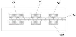
Advantageously, the second transmission device 102 includes the pulley shaft 74, the seventh pulley 72 is fixedly mounted on the outer surface of the pulley shaft 74 at the rear side of the fourth pulley 71, the seventh pulley 72 and the eighth pulley 78 are connected and driven by the fourth transmission belt 20, the eighth pulley 78 is fixedly mounted on the outer surface of a worm shaft 79, the worm shaft 79 is rotatably mounted on the rear end wall of the first cavity 12 at the lower side of the rotation support rod 24, a worm 80 is fixedly mounted on the front end outer surface of the worm shaft 79 at the front side of the eighth pulley 78, the worm 80 and the worm wheel 14 are in meshing transmission, the worm wheel 14 is fixedly mounted on the outer surface of the worm shaft 27, the worm shaft 27 is rotatably mounted on the worm shaft mounting bracket 23, the worm shaft mounting bracket 23 is fixedly mounted on the rear end wall of the first cavity 12, the left and right end outer surfaces of the worm shaft 27 are symmetrically and fixedly mounted with the fourth bevel gears 85, the fourth bevel gear 85 and the fourth bevel gear 18 are in meshing transmission, the fourth bevel gear 18 is fixedly installed on the outer surface of a roller shaft 22, the roller shaft 22 is rotatably installed on the rear end wall of the first cavity 12, and the outer surface of the front end of the roller shaft 22 is fixedly installed with the hairball removing roller 19.
Beneficially, cleaning device 103 includes mounting panel 17, the fixed opening 76 that is provided with on mounting panel 17, the opening 76 left and right sides the last rotating mounting of mounting panel 17 has a rotating turret installation axle 75, rotating turret 77 is installed to the terminal fixed surface symmetry in both sides around the rotating turret installation axle 75, clean section of thick bamboo installation axle 26 is installed in the terminal rotation of rotating turret 77 upside, the fixed surface of clean section of thick bamboo installation axle 26 installs clean section of thick bamboo 25, fixedly connected with hydraulic stem 16 on the rotating turret 77, hydraulic stem 16 keeps away from fixed connection between terminal and the pneumatic cylinder 15 of rotating turret 77 one side, the left and right symmetry fixed mounting of pneumatic cylinder 15 is in on the last side end wall of mounting panel 17.
In the initial state, the spinning dust generation cavity 52 is opened, the spinning cloth 13 is connected to the cloth collecting cylinder 70 by the spinning cloth outlet 57 bypassing the rotating rod 58 and the rotating support rod 24, and the spinning cloth 13 passes through the opening 76 and the cleaning cylinder 25.
When the device of the present invention is in operation, the motor 28 is started to drive the driving shaft 60 to rotate, so that the first belt wheel 29 rotates, the first belt wheel 29 and the second belt wheel 34 are connected and driven through the first driving belt 30, so that the turntable shaft 35 is driven to rotate, so that the turntable 36 rotates, so that the fan blades 33 are driven to rotate, so that air in the dust removing cavity 38 is exhausted through the exhaust holes 32, textile dust generated in the textile dust generating cavity 52 is sucked into the suction cavity 54 through the suction inlet 53, and is sucked into the dust removing cavity 38 through the suction pipe 56 through the connecting holes 55, the water outlet nozzle 40 is opened to spray water, so that the textile dust is wetted onto the upper end wall of the baffle 82, when the weight of the baffle 82 reaches a certain degree, so that the baffle 82 rotates downwards to drive the baffle shaft 83 to rotate, and the weight-limiting torsion spring 81 rotates, so that the wet textile dust falls into the collection box 43, and the compression spring switch 84 is driven to move downwards.
The pressure spring switch 84 sends a signal to the air pump 65, so that the air pump 65 is started, the air pump 65 inflates the air bag 63 through the connecting pipe 64, so that the air bag 63 is inflated, so that the inflation connection between the fifth pulley 62 and the fixed block 67 is realized, the driving shaft 60 rotates, so that the first bevel gear 59 is driven to rotate, the first bevel gear 59 is driven to rotate by the meshing transmission between the second bevel gear 69 and the bevel gear shaft 68, so that the fixed block 67 rotates, so that the fifth pulley 62 rotates, the fifth pulley 62 is driven to rotate by the connecting transmission between the sixth pulley 49 and the third transmission belt 42, so that the gear shaft 48 rotates, so that the gear 47 rotates, the gear 47 is driven to mesh transmission with the rack plate 46, thereby moving the rack plate 46 leftward, causing the pressure spring switch 84 to move leftward, and the pressure spring switch 84 to move leftward, causing the catch tank mounting plate 44 to move leftward, causing the catch tank 43 to move leftward out of the outlet 45.
The bevel gear shaft 68 rotates to rotate the third pulley 61, the third pulley 61 and the fourth pulley 71 are connected and driven by the second transmission belt 21 to rotate the pulley shaft 74, so that the seventh pulley 72 rotates, the seventh pulley 72 and the eighth pulley 78 are rotated by the fourth transmission belt 20, so that the worm shaft 79 rotates, so that the worm 80 rotates, the worm 80 and the worm wheel 14 are in mesh transmission, so that the worm wheel shaft 27 rotates, so that the fourth bevel gear 85 rotates, and the fourth bevel gear 85 and the fourth bevel gear 18 are in mesh transmission, so that the roller shaft 22 rotates, so that the lint removing roller 19 rotates.
The belt wheel shaft 74 rotates to drive the cloth collecting cylinder 70 to rotate, so that the textile cloth 13 moves, so that the cleaning cylinder 25 is driven to press the textile cloth 13 to rotate, so as to remove the hair bulbs and the like on the surface of the textile cloth 13, after a period of time, the hydraulic cylinder 15 is started, so that the hydraulic rod 16 is driven to move, so that the rotating frame 77 is driven to move, so that the rotating frame mounting shaft 75 is driven to rotate, so that the rotating frame 77 is driven to move, so that the cleaning cylinder 25 moves towards the hair bulb removing cylinder 19 to be attached to the hair bulb removing cylinder 19, and the hair bulb removing cylinder 19 rotates, so that the cleaning cylinder 25 is driven to rotate to remove the hair bulbs and the like on the surface of the cleaning cylinder 25.
The above embodiments are merely illustrative of the technical ideas and features of the present invention, and the purpose thereof is to enable those skilled in the art to understand the contents of the present invention and implement the present invention, and not to limit the protection scope of the present invention. All equivalent changes and modifications made according to the spirit of the present invention should be covered within the protection scope of the present invention.
Claims (5)
1. The utility model provides an equipment that is used for weaving machine weaving dirt to absorb to handle, includes the box and the box internal fixation is provided with first cavity, its characterized in that: the dust removing device comprises a first cavity, a motor, a second cavity, a dust removing box, a dust removing chamber, a dust collecting device, a dust collecting cloth outlet, a driving shaft, a first belt wheel, a second belt wheel, a first driving belt, a second belt wheel, a third belt wheel, a fourth belt wheel, a third belt wheel, a fourth belt wheel, a fifth belt wheel, a sixth belt wheel, a fifth belt wheel, a sixth belt wheel, a fifth belt wheel, a sixth belt wheel, a fifth belt wheel, a sixth belt wheel, a sixth belt, a fifth belt, a sixth belt, a fourth belt, a sixth belt, a fifth belt, a fourth belt, a sixth belt, a fifth belt, a sixth belt, a fifth belt, a sixth belt, a fourth belt, a sixth belt, a fourth belt, a sixth belt, a fifth belt, a fourth belt, a fourth belt, a fourth belt, a first bevel gear is fixedly mounted at the tail end of the lower side of the driving shaft, the first bevel gear and a second bevel gear are in meshing transmission, the second bevel gear is fixedly mounted on the outer surface of the tail end of the front side of a bevel gear shaft, the bevel gear shaft is rotatably mounted on the rear end wall of the first cavity, a first transmission device for transmission between the bevel gear shaft and a collecting box mounting plate is mounted on the outer surface of the bevel gear shaft at the rear side of the second bevel gear, a collecting box is fixedly mounted on the outer surface of the upper end wall of the collecting box mounting plate, a third belt wheel is fixedly mounted on the outer surface of the bevel gear shaft at the front side of the first transmission device, the third belt wheel and a fourth belt wheel are in connection transmission through a second transmission belt, the fourth belt wheel is fixedly mounted on the outer surface of a belt wheel shaft, and the belt wheel shaft is rotatably mounted on the rear end wall of the first cavity, fourth band pulley rear side the surface mounting of band pulley axle is used for driven second transmission between band pulley axle and the round of hair removal cylinder, the band pulley axle front side the terminal surface fixed mounting of front side of band pulley axle has a receipts cloth section of thick bamboo, be connected with weaving cloth on the receipts cloth section of thick bamboo, weaving cloth is kept away from receive cloth section of thick bamboo one side is terminal to be passed through weaving cloth exit linkage is in the weaving cloth exit, weaving cloth export right side rotate on the back side end wall of first cavity and install the dwang, weaving cloth is in on the dwang, install between the round of hair removal cylinder and be used for weaving cloth surface gets rid of the cleaning device of the hair removal ball, the cleaning device upside rotate on the back side end wall of first cavity and install the rotation bracing piece, weaving cloth twine around the surface of rotation bracing piece.
2. An apparatus for dust absorption treatment of textile machines, according to claim 1, characterized in that: the dust collector comprises the turntable shaft, the outer surface of the tail end of the lower side of the turntable shaft is fixedly provided with a turntable, the turntable is far away from the outer surface of the fixed circumference of the end wall of one side of the turntable shaft and is provided with fan blades, the symmetrical arrays of the left side and the right side of the turntable shaft are fixedly provided with exhaust holes on the end wall of the upper side of the dust removal cavity, a partition plate is fixedly arranged between the end walls of the dust removal cavity and is provided with through holes, the left end wall and the right end wall of the dust removal cavity on the lower side of the partition plate are fixedly provided with water outlet nozzles, the lower end wall of the dust removal cavity is symmetrically and rotatably provided with baffle plates, the outer surface of the baffle plates is fixedly provided with baffle plates, the baffle plates are connected with the end walls of the dust removal cavity through weight-limiting torsion springs, the water outlet nozzles are fixedly provided with inlet holes on the end wall of the right side of the dust removal cavity, the textile dust generating device comprises an inlet, a textile dust generating cavity, a connecting hole, a suction pipe, a suction port array and a dust collecting cavity, wherein the inlet is fixedly connected to the inlet, the tail end of one side, far away from the inlet, of the suction pipe is fixedly connected with the connecting hole, the connecting hole is fixedly formed in the upper side end wall of the textile dust generating cavity, a suction cavity is fixedly formed in the upper side end wall of the textile dust generating cavity and is arranged on the lower side of the connecting hole, the suction cavity is communicated with the textile dust generating cavity through a suction port, and the suction port array is fixedly arranged on the upper side end wall of the textile dust generating cavity and is arranged on the lower side of the suction cavity.
3. An apparatus for dust absorption treatment of textile machines, according to claim 1, characterized in that: the first transmission device comprises the bevel gear shaft, the outer surface of the bevel gear shaft at the rear side of the third belt wheel is fixedly provided with a fixed block, the fixed block is internally and vertically provided with an air pump, the air pump is fixedly connected with a connecting pipe, the connecting pipe is fixedly arranged in the fixed block, the connecting pipe is far away from the fixed connection between the tail end of one side of the air pump and an air bag, the air bag is arranged in an air bag cavity, the fixed vertical symmetry of the air bag cavity is arranged on the end wall of one side of the fifth belt wheel, the fifth belt wheel is rotatably arranged on the outer surface of the end part of one side of the bevel gear shaft, the fixed block is far away from the outer surface of the end part of one side of the bevel gear shaft, the fifth belt wheel and the sixth belt wheel are connected and transmitted through a third transmission belt, the sixth belt wheel is fixedly arranged on the outer surface of the gear shaft, the gear shaft is rotatably arranged on the end wall of the rear side of the first cavity at the lower side of the dust removal box, the utility model discloses a quick-witted rack, including rack, gear shaft, rack board, rack switch, rack board, the terminal fixedly connected with of upside, the terminal fixedly connected with of pressure spring switch, the collecting box mounting panel.
4. An apparatus for the dust absorption treatment of textile fabrics by textile machines, as claimed in claim 1, characterized in that: the second transmission device comprises the pulley shaft, a seventh pulley is fixedly arranged on the outer surface of the pulley shaft at the rear side of the fourth pulley, the seventh pulley and an eighth pulley are in connection transmission through a fourth transmission belt, the eighth pulley is fixedly arranged on the outer surface of a worm shaft, the worm shaft is rotatably arranged on the rear end wall of the first cavity at the lower side of the rotating support rod, a worm is fixedly arranged on the outer surface of the tail end at the front side of the worm shaft at the front side of the eighth pulley, the worm and the worm wheel are in meshing transmission, the worm wheel is fixedly arranged on the outer surface of the worm shaft, the worm shaft is rotatably arranged on a worm shaft mounting frame which is fixedly arranged on the rear end wall of the first cavity, fourth bevel gears are symmetrically and fixedly arranged on the outer surfaces of the left and right tail ends of the worm shaft, and the fourth bevel gears are in meshing transmission with the fourth bevel gears, the fourth bevel gear is fixedly installed on the outer surface of a roller shaft, the roller shaft is rotatably installed on the rear end wall of the first cavity, and the outer surface of the tail end of the front side of the roller shaft is fixedly provided with the hair removing ball roller.
5. An apparatus for dust absorption treatment of textile machines, according to claim 1, characterized in that: cleaning device includes the mounting panel, the fixed opening that is provided with on the mounting panel, the opening left and right sides rotate on the mounting panel and install the rotating turret installation axle, the rotating turret is installed to the terminal fixed surface symmetry in both sides around the rotating turret installation axle, the terminal rotation of rotating turret upside installs clean section of thick bamboo installation axle, the fixed surface of clean section of thick bamboo installation axle installs clean section of thick bamboo, fixedly connected with hydraulic stem on the rotating turret, the hydraulic stem is kept away from fixed connection between rotating turret one side end and the pneumatic cylinder, pneumatic cylinder bilateral symmetry fixed mounting is in on the upside end wall of mounting panel.
Priority Applications (1)
| Application Number | Priority Date | Filing Date | Title |
|---|---|---|---|
| CN202011214062.4A CN112281287B (en) | 2020-11-04 | 2020-11-04 | Equipment for absorbing and treating textile dust of textile machine |
Applications Claiming Priority (1)
| Application Number | Priority Date | Filing Date | Title |
|---|---|---|---|
| CN202011214062.4A CN112281287B (en) | 2020-11-04 | 2020-11-04 | Equipment for absorbing and treating textile dust of textile machine |
Publications (2)
| Publication Number | Publication Date |
|---|---|
| CN112281287A CN112281287A (en) | 2021-01-29 |
| CN112281287B true CN112281287B (en) | 2022-08-26 |
Family
ID=74352058
Family Applications (1)
| Application Number | Title | Priority Date | Filing Date |
|---|---|---|---|
| CN202011214062.4A Active CN112281287B (en) | 2020-11-04 | 2020-11-04 | Equipment for absorbing and treating textile dust of textile machine |
Country Status (1)
| Country | Link |
|---|---|
| CN (1) | CN112281287B (en) |
Families Citing this family (1)
| Publication number | Priority date | Publication date | Assignee | Title |
|---|---|---|---|---|
| CN113123036A (en) * | 2021-03-17 | 2021-07-16 | 湖南国盛服饰有限公司 | Textile clothing is with destatic weaving defeathering device |
Family Cites Families (6)
| Publication number | Priority date | Publication date | Assignee | Title |
|---|---|---|---|---|
| US5402809A (en) * | 1994-01-11 | 1995-04-04 | Smith; Jeffrey P. | Apparatus for cleaning industrial safety apparel |
| EP2303086B1 (en) * | 2008-06-18 | 2021-07-28 | Cintas Corporate Services, Inc. | Automated mat cleaning and handling system and method |
| CN103952878A (en) * | 2014-04-10 | 2014-07-30 | 佛山市高明新明和机械技术研究开发有限公司 | Automatic fabric cleaning system |
| CN108149431A (en) * | 2018-03-05 | 2018-06-12 | 湖州市菱湖重兆金辉丝织厂 | A kind of fabric drying dust-extraction unit of rollforming |
| CN210066290U (en) * | 2019-05-24 | 2020-02-14 | 江苏七彩纺织染整有限公司 | Weaving is with weaving quick-witted weaving dirt collection device |
| CN211771744U (en) * | 2019-12-15 | 2020-10-27 | 刘孟龙 | Weaving machine weaving dirt collection device |
-
2020
- 2020-11-04 CN CN202011214062.4A patent/CN112281287B/en active Active
Also Published As
| Publication number | Publication date |
|---|---|
| CN112281287A (en) | 2021-01-29 |
Similar Documents
| Publication | Publication Date | Title |
|---|---|---|
| CN211052076U (en) | Printing and dyeing weaving cloth defeathering device | |
| CN111748999B (en) | Washing equipment for textile material processing | |
| CN213740020U (en) | Belt cleaning device is used in dacron processing | |
| CN218707689U (en) | Surface lint removing equipment for knitted fabric processing | |
| CN109183326A (en) | A kind of drying box of textile printing and dyeing | |
| CN112281287B (en) | Equipment for absorbing and treating textile dust of textile machine | |
| CN210529138U (en) | Spinning dust treatment device for grey-colored spun yarns | |
| CN210314995U (en) | Adsorption device of pad dyeing machine | |
| CN112080871A (en) | Dyeing apparatus is used in surface fabric production based on 5G technique | |
| CN215490857U (en) | Drying treatment device for improving comprehensive yarn dewatering efficiency | |
| CN110899290A (en) | Collecting device for textile dust of textile machine | |
| CN211493294U (en) | Printing device for chemical fiber cloth | |
| CN212505366U (en) | Drying device for textile fabric | |
| CN213624727U (en) | Weaving is with weaving cloth belt cleaning device | |
| CN213740010U (en) | Weaving is with weaving cloth cleaning device | |
| CN210856607U (en) | Weaving cloth belt cleaning device of weaving cloth production usefulness | |
| CN220013156U (en) | Pretreatment device of setting machine | |
| CN220689655U (en) | Textile fabric air-drying device for spinning | |
| CN212247470U (en) | Production device of radiation-proof double-layer woven cloth | |
| CN212603989U (en) | Dust collection type weaving and printing device for spinning | |
| CN215976450U (en) | Waste heat recovery device of sizing machine | |
| CN218059494U (en) | Chemical fiber textile processing belt cleaning device | |
| CN215887393U (en) | Cotton thread lint removing processing device for cloth spinning | |
| CN219527017U (en) | Textile fabric cleaning device | |
| CN215405096U (en) | High-speed ironing device for knitted fabric |
Legal Events
| Date | Code | Title | Description |
|---|---|---|---|
| PB01 | Publication | ||
| PB01 | Publication | ||
| SE01 | Entry into force of request for substantive examination | ||
| SE01 | Entry into force of request for substantive examination | ||
| TA01 | Transfer of patent application right | ||
| TA01 | Transfer of patent application right |
Effective date of registration: 20220805 Address after: 252000 building 3, kanglaide Health Industrial Park, Jiuzhou street, high tech Zone, Liaocheng City, Shandong Province Applicant after: Caijin Zhichan information technology (Shandong) Co.,Ltd. Address before: 201601 No.85, Lane 103, Sizuan Road, Songjiang District, Shanghai Applicant before: Wei Wenjie |
|
| GR01 | Patent grant | ||
| GR01 | Patent grant |