CN112255116B - Comprehensive test bed for performance test of light steel keel - Google Patents
Comprehensive test bed for performance test of light steel keel Download PDFInfo
- Publication number
- CN112255116B CN112255116B CN202011135679.7A CN202011135679A CN112255116B CN 112255116 B CN112255116 B CN 112255116B CN 202011135679 A CN202011135679 A CN 202011135679A CN 112255116 B CN112255116 B CN 112255116B
- Authority
- CN
- China
- Prior art keywords
- clamping seat
- transmission belt
- belt
- plate
- seat
- Prior art date
- Legal status (The legal status is an assumption and is not a legal conclusion. Google has not performed a legal analysis and makes no representation as to the accuracy of the status listed.)
- Active
Links
Images

Classifications
-
- G—PHYSICS
- G01—MEASURING; TESTING
- G01N—INVESTIGATING OR ANALYSING MATERIALS BY DETERMINING THEIR CHEMICAL OR PHYSICAL PROPERTIES
- G01N3/00—Investigating strength properties of solid materials by application of mechanical stress
- G01N3/22—Investigating strength properties of solid materials by application of mechanical stress by applying steady torsional forces
-
- G—PHYSICS
- G01—MEASURING; TESTING
- G01N—INVESTIGATING OR ANALYSING MATERIALS BY DETERMINING THEIR CHEMICAL OR PHYSICAL PROPERTIES
- G01N3/00—Investigating strength properties of solid materials by application of mechanical stress
- G01N3/08—Investigating strength properties of solid materials by application of mechanical stress by applying steady tensile or compressive forces
- G01N3/10—Investigating strength properties of solid materials by application of mechanical stress by applying steady tensile or compressive forces generated by pneumatic or hydraulic pressure
- G01N3/12—Pressure testing
-
- G—PHYSICS
- G01—MEASURING; TESTING
- G01N—INVESTIGATING OR ANALYSING MATERIALS BY DETERMINING THEIR CHEMICAL OR PHYSICAL PROPERTIES
- G01N3/00—Investigating strength properties of solid materials by application of mechanical stress
- G01N3/30—Investigating strength properties of solid materials by application of mechanical stress by applying a single impulsive force, e.g. by falling weight
-
- G—PHYSICS
- G01—MEASURING; TESTING
- G01N—INVESTIGATING OR ANALYSING MATERIALS BY DETERMINING THEIR CHEMICAL OR PHYSICAL PROPERTIES
- G01N3/00—Investigating strength properties of solid materials by application of mechanical stress
- G01N3/32—Investigating strength properties of solid materials by application of mechanical stress by applying repeated or pulsating forces
- G01N3/36—Investigating strength properties of solid materials by application of mechanical stress by applying repeated or pulsating forces generated by pneumatic or hydraulic means
-
- G—PHYSICS
- G01—MEASURING; TESTING
- G01N—INVESTIGATING OR ANALYSING MATERIALS BY DETERMINING THEIR CHEMICAL OR PHYSICAL PROPERTIES
- G01N2203/00—Investigating strength properties of solid materials by application of mechanical stress
- G01N2203/0001—Type of application of the stress
- G01N2203/001—Impulsive
-
- G—PHYSICS
- G01—MEASURING; TESTING
- G01N—INVESTIGATING OR ANALYSING MATERIALS BY DETERMINING THEIR CHEMICAL OR PHYSICAL PROPERTIES
- G01N2203/00—Investigating strength properties of solid materials by application of mechanical stress
- G01N2203/0014—Type of force applied
- G01N2203/0016—Tensile or compressive
- G01N2203/0019—Compressive
-
- G—PHYSICS
- G01—MEASURING; TESTING
- G01N—INVESTIGATING OR ANALYSING MATERIALS BY DETERMINING THEIR CHEMICAL OR PHYSICAL PROPERTIES
- G01N2203/00—Investigating strength properties of solid materials by application of mechanical stress
- G01N2203/0014—Type of force applied
- G01N2203/0021—Torsional
-
- G—PHYSICS
- G01—MEASURING; TESTING
- G01N—INVESTIGATING OR ANALYSING MATERIALS BY DETERMINING THEIR CHEMICAL OR PHYSICAL PROPERTIES
- G01N2203/00—Investigating strength properties of solid materials by application of mechanical stress
- G01N2203/003—Generation of the force
- G01N2203/0042—Pneumatic or hydraulic means
- G01N2203/0044—Pneumatic means
-
- G—PHYSICS
- G01—MEASURING; TESTING
- G01N—INVESTIGATING OR ANALYSING MATERIALS BY DETERMINING THEIR CHEMICAL OR PHYSICAL PROPERTIES
- G01N2203/00—Investigating strength properties of solid materials by application of mechanical stress
- G01N2203/0058—Kind of property studied
- G01N2203/0069—Fatigue, creep, strain-stress relations or elastic constants
- G01N2203/0073—Fatigue
Abstract
The invention discloses a light steel keel performance test comprehensive test bed which comprises a base, wherein a left clamping seat and a right clamping seat are slidably mounted on the base, the left clamping seat and the right clamping seat are jointly connected with a first transmission belt, and the left clamping seat is connected with a linear driver; the first transmission belt is connected with a second transmission belt through a transmission mechanism, the second transmission belt is connected with a swing mechanism, and the swing mechanism is connected with a plurality of stressing rods for exerting force on the edge of the light steel keel; the utility model discloses a light gauge steel joist, including left side holder and right holder, the left side holder has the overlap joint board with right holder top configuration jointly, the overlap joint board lower surface is provided with displacement adjustable and strikes the seat, it disposes the gravity piece that is used for providing the impact force to light gauge steel to strike the seat. The test bed integrates various testing devices into a whole, only needs to clamp a test piece once, and can achieve the purpose of quick and convenient testing through switching among various testing clamps.
Description
Technical Field
The invention relates to the field of building material inspection, in particular to a comprehensive test bed for testing the performance of a light steel keel.
Background
The light steel keel is a metal framework for buildings, which is made of high-quality continuous hot-galvanized plate strips serving as raw materials and rolled by a cold bending process, and is used for modeling and decorating non-bearing walls and building roofs. It is suitable for the modeling decoration of various building roofs, the internal and external walls of buildings and the basic material of a shed frame type suspended ceiling. Because certain bearing and shock resistance need to have, light gauge steel need carry out multiple performance test before dispatching from the factory and just can come into operation, for example pressure fatigue test, torsion test, impact test, every performance test all need dispose a dedicated test equipment among the prior art, the test of a pair light gauge steel need operate on a plurality of equipment just can accomplish, purchase, use and maintenance of many equipment are a very big fund input to the enterprise, also seriously occupy the laboratory site simultaneously, need dispose great test space. Clamping and dismounting a test piece for multiple times on multiple test devices can damage the surface of the light steel keel, the attractiveness and the use performance are affected, multiple clamping tests occupy more time, the test period of the light steel keel is longer, and the production progress is seriously delayed.
Disclosure of Invention
In order to solve the problems, the invention discloses a comprehensive test bed for testing the performance of a light steel keel, which integrates a plurality of test devices into a whole, and can achieve the aim of quick and convenient test by clamping a test piece once and switching various test fixtures.
A comprehensive test bed for performance test of a light steel keel comprises a base, wherein a left clamping seat and a right clamping seat are slidably mounted on the base, the left clamping seat and the right clamping seat are jointly connected with a first transmission belt, the left clamping seat is connected with a linear driver, the linear driver drives the left clamping seat to move, and the left clamping seat and the right clamping seat oppositely move under the transmission of the first transmission belt;
the first transmission belt is connected with a second transmission belt through a transmission mechanism, the second transmission belt is connected with a swing mechanism, and the swing mechanism is connected with a plurality of stress applying rods for applying force to the edge of the light steel keel;
the utility model discloses a light gauge steel joist, including left side holder and right holder, the left side holder has the overlap joint board with right holder top configuration jointly, the overlap joint board lower surface is provided with displacement adjustable and strikes the seat, it disposes the gravity piece that is used for providing the impact force to light gauge steel to strike the seat.
Preferably, the left clamping seat is connected with a first connecting plate, the first connecting plate is connected with the upper half portion of the first transmission belt, the right clamping seat is connected with a second connecting plate, and the second connecting plate is connected with the lower half portion of the first transmission belt.
Preferably, the linear actuator is an electric cylinder or an air cylinder.
Preferably, both ends of the first transmission belt are respectively connected with a first belt wheel and a second belt wheel, the first belt wheel is coaxially connected with a third belt wheel, and the third belt wheel is in transmission connection with a fourth belt wheel through a second transmission belt.
Preferably, the fourth belt pulley is connected with a switching rod, one end of the switching rod, which is far away from the fourth belt pulley, is connected with a swinging rod, and the swinging rod is connected with the stressing rod.
Preferably, the swing rod penetrates through the lap plate, and the parts of the swing rod on two sides of the lap plate are respectively connected with at least one stressing rod.
Preferably, the lap joint plate is provided with a pin shaft for temporarily fixing the stressing rod.
Preferably, an X-direction guide rail sliding block mechanism is arranged on the lapping plate, the X-direction guide rail sliding block mechanism is connected with a Y-direction guide rail sliding block mechanism, and the Y-direction guide rail sliding block mechanism is connected with the impact seat.
Preferably, the impact seat is an electromagnet mounting seat.
Preferably, left side holder and right holder all include the riser, sliding connection has last clamp splice and lower clamp splice on the riser.
The invention has the beneficial effects that:
according to the invention, the power mechanisms for the pressure fatigue test and the torque force test are integrated into one mechanism through the first transmission belt and the second transmission belt, the lapping seats are arranged above the left clamping seat and the right clamping seat, and the impact test device is arranged on the lapping seats, so that three test items of the pressure fatigue test, the torque force test and the impact test can be simultaneously completed by means of one-time clamping, the test time is saved, the convenience and the high efficiency are realized, and the equipment integration level is high.
Drawings
In order to more clearly illustrate the embodiments of the present application or the technical solutions in the prior art, the drawings used in the description of the embodiments or the prior art will be briefly described below, it is obvious that the drawings in the following description are only some embodiments of the present application, and for those skilled in the art, other drawings can be obtained according to the drawings without creative efforts.
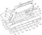
FIG. 1 is a first block diagram of the present invention;
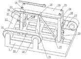
FIG. 2 is a second embodiment of the present invention;
FIG. 3 is a third embodiment of the present invention;
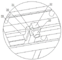
FIG. 4 is an enlarged view of A in FIG. 3;
in the figure: 1. the device comprises a base, 2, a guide rail, 3, a first transmission belt, 4, a belt wheel support, 5, a second belt wheel, 6, an upper half, 7, a lower half, 8, a first connecting plate, 9, a driving connecting plate, 10, a second connecting plate, 11, a first belt wheel, 12, a linkage shaft, 13, a first stress rod, 14, a pin shaft, 15, a second stress rod, 16, a swinging rod, 17, a light steel keel, 18, a third belt wheel, 19, a fourth belt wheel, 20, a second transmission belt, 21, a switching rod, 22, a third stress rod, 23, a fourth stress rod, 24, a bridging plate, 25, a screw, 26, a screw rod, 27, an upper clamping block, 28, a lower clamping block, 29, an X-direction guide rail, 30, an X-direction sliding block, 31, a Y-direction sliding block, 32, a Y-direction guide rail, 33, an impact seat, 34, a vertical plate, 35 and a linear driver.
Detailed Description
The technical solutions in the embodiments of the present application will be described clearly and completely with reference to the drawings in the embodiments of the present application, and it is obvious that the described embodiments are only a part of the embodiments of the present application, and not all of the embodiments. All other embodiments, which can be derived by a person skilled in the art from the embodiments of the present application without making any creative effort, shall fall within the protection scope of the present application.
The invention discloses a light steel keel performance test comprehensive test bed as shown in figures 1-4, wherein a guide rail 2 is arranged on the upper surface of a base 1 at the position of the front central line and the rear central line, two sliding blocks are arranged on the guide rail in a matching way, each sliding block is connected with a vertical plate 34, the outer side surface of each vertical plate is provided with a screw rod 26 through a bearing seat, the screw rod is respectively connected with an upper clamping block 27 and a lower clamping block 28 in a threaded way, the thread turning directions of the upper clamping block and the lower clamping block are opposite, and the thread turning directions on the corresponding screw rods are also opposite.
The riser 34 side of left end detachably is connected with drive connecting plate 9, and this drive connecting plate is connected with linear actuator 35, and this linear actuator is preferred cylinder or electronic jar, linear actuator and base 1 fixed connection. The riser side of left end is connected with first drive belt 3's first 6 through first connecting plate 8, the riser side of right-hand member passes through second connecting plate 10 and is connected with first drive belt 3's lower half 7, the driver drives the riser of left end and the holder of being connected with the riser and slides along the base side to side, transmission through first drive belt, the riser of right-hand member and the holder of being connected with the riser also slide along the base side to side, and control the gliding direction of holder and be opposite, light gauge steel 17 is on a left side, pressure or release are applyed under the centre gripping of right side holder, and then reach pressure fatigue test. The base is provided with a graduated scale for marking the moving distance of the left clamping seat and the right clamping seat. This application can also add pressure sensor between grip slipper and light gauge steel for the accuracy is exerted pressure to the light gauge steel.
Two ends of the first transmission belt are respectively connected with a first belt wheel 11 and a second belt wheel 5, the first belt wheel 5 is coaxially connected with a third belt wheel 18 through a linkage shaft 12 in a transmission way, and the third belt wheel is connected with a fourth belt wheel 19 through a second transmission belt 20 in a transmission way. The spoke of the fourth belt wheel is connected with the adapter rod 21 through a screw, the upper end of the adapter rod is connected with the swing rod 16, the swing rod is rotatably connected with the lap plate 24 and penetrates through the lap plate, the part of the swing rod, which is positioned at the front end of the lap plate, is detachably connected with the first stress application rod 13 and the second stress application rod 15, and the part of the swing rod, which is positioned at the rear end of the lap plate, is detachably connected with the third stress application rod 22 and the fourth stress application rod 23. During the experiment, the preceding left end of light gauge steel is connected to first grimper, the back right-hand member of light gauge steel is connected to the third grimper, drive connecting plate 9 is installed on first drive belt from riser 34 dismantles, demolish first connecting plate and second connecting plate from first drive belt temporarily simultaneously, the driver action, drive first drive belt and rotate along the band pulley, transmission through universal driving shaft 12 and second drive belt 20, drive fourth band pulley 19 and rotate, and then drive changeover lever 21 and use swinging arms 16 as the center swing, and then drive first grimper and third grimper and respectively to two diagonal alternate application of force of light gauge steel, realize the torsion test. At this time, the second stress application rod and the fourth stress application rod are connected with the lapping rod through the pin shaft 14 and do not participate in the test. After the test, the connection points of the first stress application rod, the third stress application rod and the swinging rod are loosened, the first stress application rod and the third stress application rod are rotated to the positions connected with the lap joint plate through the pin shafts, and the second stress application rod and the fourth stress application rod are connected to the other two angular points of the light steel keel to continue the torsion test.
When the pressure fatigue test is carried out, the lapping plate and the swinging rod, the stress application rod and the adapter rod which are connected with the lapping plate are all detached from the device, the lapping plate is arranged on two vertical plates through the connecting screws 25 when the torque test is required, and the adapter rod is connected with the spoke of the fourth belt wheel through the screws
The lower surface of the lapping plate 24 is provided with an X-direction guide rail 29, an X-direction slide block 30 is arranged on the X-direction guide rail in a sliding way, a Y-direction guide rail 32 is arranged below the X-direction slide block, a Y-direction slide block 31 is arranged below the Y-direction guide rail, the lower part of the Y-direction slide block is connected with an impact seat 33, the impact seat is an electromagnet installation seat, the impact block is electromagnetically connected after the installation seat is electrified, the X-direction slide block and the Y-direction slide block are adjusted, and power is cut off after the position is adjusted, so that impact test can be carried out on points within the set range of the light steel keel.
The riser 34 is the multisection nested structure in this application, through the height of adjustment riser, can accomplish the impact test experiment under the different heights. When adjusting the riser height, need demolish the changeover bar from the fourth band pulley.
The whole pressure fatigue test, torsion test and impact test can be completed on one test bed, and the test is efficient and convenient; and only one clamping work of the light steel keel is needed, so that repeated clamping and alignment and clamping damage to the light steel keel are prevented.
The previous description of the disclosed embodiments is provided to enable any person skilled in the art to make or use the present application. Various modifications to these embodiments will be readily apparent to those skilled in the art, and the generic principles defined herein may be applied to other embodiments without departing from the spirit or scope of the application. Thus, the present application is not intended to be limited to the embodiments shown herein but is to be accorded the widest scope consistent with the principles and novel features disclosed herein.
Claims (5)
1. The comprehensive test bed for the performance test of the light steel keel is characterized by comprising a base (1), wherein a left clamping seat and a right clamping seat are slidably mounted on the base, the left clamping seat and the right clamping seat are jointly connected with a first transmission belt (3), the left clamping seat is connected with a linear driver (35), the linear driver drives the left clamping seat to move, and the left clamping seat and the right clamping seat oppositely move under the transmission of the first transmission belt (3);
the first transmission belt is connected with a second transmission belt (20) through a transmission mechanism, the second transmission belt is connected with a swing mechanism, and the swing mechanism is connected with a plurality of stress application rods for applying force to the edge of the light steel keel;
a lapping plate (24) is jointly arranged above the left clamping seat and the right clamping seat, an impact seat (33) with adjustable displacement is arranged on the lower surface of the lapping plate, and the impact seat is provided with a gravity block for providing impact force to the light steel keel;
the left clamping seat is connected with a first connecting plate (8), the first connecting plate (8) is connected with the upper half part (6) of the first transmission belt (3), the right clamping seat is connected with a second connecting plate (10), and the second connecting plate (10) is connected with the lower half part (7) of the first transmission belt (3);
the upper surface of the base 1 is provided with a guide rail (2) at the position of a front central line and a rear central line, the guide rail is provided with two sliders in a matching way, each slider is connected with a vertical plate (34), the side surface of the vertical plate (34) at the left end is detachably connected with a driving connecting plate (9), the driving connecting plate is connected with a linear driver (35), the linear driver is fixedly connected with the base (1), the side surface of the vertical plate at the left end is connected with the upper half part (6) of a first transmission belt (3) through a first connecting plate (8), the side surface of the vertical plate at the right end is connected with the lower half part (7) of the first transmission belt (3) through a second connecting plate (10), the driver drives the vertical plate at the left end and a clamping seat connected with the vertical plate to slide left and right along the base, the vertical plate at the right end and the clamping seat connected with the vertical plate also slide left and right along the base through the transmission of the first transmission belt, and the sliding directions of the left and right clamping seats are opposite;
two ends of the first transmission belt are respectively connected with a first belt wheel (11) and a second belt wheel (5), the first belt wheel (5) is coaxially connected with a third belt wheel (18) in a transmission way through a linkage shaft (12), and the third belt wheel is connected with a fourth belt wheel (19) in a transmission way through a second transmission belt (20);
the spoke of the fourth belt wheel is connected with an adapter rod (21) through a screw, the upper end of the adapter rod is connected with a swing rod (16), the swing rod is rotatably connected with a lap plate (24) and penetrates through the lap plate (24), the part of the swing rod, which is positioned at the front end of the lap plate, is detachably connected with a first stress application rod (13) and a second stress application rod (15), and the part of the swing rod, which is positioned at the rear end of the lap plate, is detachably connected with a third stress application rod (22) and a fourth stress application rod (23);
during the experiment, the preceding left end of light gauge steel is connected to first grimper, the back right-hand member of light gauge steel is connected to the third grimper, drive connecting plate (9) are pulled down from riser (34) and are installed on first drive belt, demolish first connecting plate and second connecting plate from first drive belt temporarily simultaneously, the driver action, drive first drive belt and rotate along the band pulley, transmission through universal driving shaft (12) and second drive belt (20), drive fourth band pulley (19) and rotate, and then drive switching pole (21) and use swinging arms (16) to swing as the center, and then drive first grimper and third grimper and respectively to two diagonal alternate application of force of light gauge steel, realize the torsion test.
2. The comprehensive test bed for testing the performance of the light steel keel according to claim 1, wherein the linear driver is an electric cylinder or an air cylinder.
3. The comprehensive test bed for testing the performance of the light steel keel according to claim 2, wherein the lapping plate is provided with a pin shaft (14) for temporarily fixing the stressing rod.
4. The light steel keel performance test integrated test bed according to claim 2, wherein an X-direction guide rail sliding block mechanism is arranged on the lapping plate, a Y-direction guide rail sliding block mechanism is connected with the X-direction guide rail sliding block mechanism, and the Y-direction guide rail sliding block mechanism is connected with the impact seat (33).
5. The light gauge steel performance test integrated test bench of claim 2, characterized in that the impact seat (33) is an electromagnet mounting seat.
Priority Applications (1)
| Application Number | Priority Date | Filing Date | Title |
|---|---|---|---|
| CN202011135679.7A CN112255116B (en) | 2020-10-22 | 2020-10-22 | Comprehensive test bed for performance test of light steel keel |
Applications Claiming Priority (1)
| Application Number | Priority Date | Filing Date | Title |
|---|---|---|---|
| CN202011135679.7A CN112255116B (en) | 2020-10-22 | 2020-10-22 | Comprehensive test bed for performance test of light steel keel |
Publications (2)
| Publication Number | Publication Date |
|---|---|
| CN112255116A CN112255116A (en) | 2021-01-22 |
| CN112255116B true CN112255116B (en) | 2022-10-21 |
Family
ID=74263340
Family Applications (1)
| Application Number | Title | Priority Date | Filing Date |
|---|---|---|---|
| CN202011135679.7A Active CN112255116B (en) | 2020-10-22 | 2020-10-22 | Comprehensive test bed for performance test of light steel keel |
Country Status (1)
| Country | Link |
|---|---|
| CN (1) | CN112255116B (en) |
Families Citing this family (2)
| Publication number | Priority date | Publication date | Assignee | Title |
|---|---|---|---|---|
| CN113125257B (en) * | 2021-03-30 | 2023-04-11 | 上海盈达空调设备股份有限公司 | Be used for galvanized sheet plate body deformation test frock |
| CN114527023B (en) * | 2022-04-24 | 2022-07-01 | 徐州璞素室内装饰材料有限公司 | Device for detecting strength of ceiling keel frame after manufacturing and forming |
Citations (2)
| Publication number | Priority date | Publication date | Assignee | Title |
|---|---|---|---|---|
| US4237719A (en) * | 1977-10-26 | 1980-12-09 | Mitsuboshi Belting Limited | Apparatus for testing power transmission belts |
| CN111307629A (en) * | 2020-03-30 | 2020-06-19 | 南京理工军邦特种智能装备研究院有限公司 | Material impact resistance detection equipment and detection method |
Family Cites Families (20)
| Publication number | Priority date | Publication date | Assignee | Title |
|---|---|---|---|---|
| US3991608A (en) * | 1970-10-26 | 1976-11-16 | Owens-Illinois, Inc. | Impact simulator method and apparatus |
| JPS5722099Y2 (en) * | 1977-10-26 | 1982-05-13 | ||
| JP2011149696A (en) * | 2008-05-09 | 2011-08-04 | Kokusai Keisokki Kk | Impact testing device |
| ES2748863T3 (en) * | 2011-04-12 | 2020-03-18 | Kokusai Keisokuki Kk | Rotational Torsion Tester |
| CN103293066B (en) * | 2013-05-10 | 2015-04-08 | 吉林大学 | Precision material micro mechanical property in-situ torsion testing platform |
| TW201508274A (en) * | 2013-08-29 | 2015-03-01 | Hong Ann Tool Ind Co Ltd | Torque testing machine having dual drive modes |
| JP6314642B2 (en) * | 2014-05-13 | 2018-04-25 | 横浜ゴム株式会社 | Device and method for measuring running resistance of conveyor belt |
| CN104500502B (en) * | 2014-11-24 | 2016-08-24 | 吉林大学 | Experimental facilities for hydraulic cylinder durability test |
| CN204882237U (en) * | 2015-07-06 | 2015-12-16 | 江苏东方航天校准检测有限公司 | Little moment pulling force machine |
| CN204924775U (en) * | 2015-08-06 | 2015-12-30 | 山东鲁科工程质量检测有限责任公司 | Light gauge steel testing stand |
| CN106226058A (en) * | 2016-08-22 | 2016-12-14 | 中国建材检验认证集团浙江有限公司 | A kind of body of wall lightgage steel joist mechanical property test device for building and test method |
| DE102016123585A1 (en) * | 2016-12-06 | 2018-06-07 | MonTech System Solutions GmbH | Gripper for test specimen, raw material positioning device, raw material and specimen handling system and viscoelastic material testing system |
| US11022532B2 (en) * | 2017-12-08 | 2021-06-01 | Wuhan China Star Optoelectronics Semiconductor Display Technology Co., Ltd. | Pressure and hardness tester of planar test piece |
| CN208520695U (en) * | 2018-07-18 | 2019-02-19 | 东莞市恒塑环保建材有限公司 | A kind of keel detection device for building |
| CN208937432U (en) * | 2018-09-30 | 2019-06-04 | 广州市锐美汽车零部件有限公司 | A kind of torque test device of welding product |
| CN110773991A (en) * | 2019-08-01 | 2020-02-11 | 珠海智新自动化科技有限公司 | Scraper installation mechanism of selenium drum waste powder bin assembly line |
| CN110793692B (en) * | 2019-10-22 | 2021-06-22 | 苏州微比特自动化有限公司 | Friction force detection equipment |
| CN211122346U (en) * | 2019-12-01 | 2020-07-28 | 江西众益嘉科技有限公司 | Multifunctional testing equipment for machining mechanical parts |
| CN111735689B (en) * | 2020-07-29 | 2022-07-15 | 安徽荣港建筑工程有限公司 | Steel bridge bituminous pavement shearing fatigue degree detection equipment |
| CN211668957U (en) * | 2020-08-07 | 2020-10-13 | 赵晓蕾 | Device for testing tensile property of optical fiber |
-
2020
- 2020-10-22 CN CN202011135679.7A patent/CN112255116B/en active Active
Patent Citations (2)
| Publication number | Priority date | Publication date | Assignee | Title |
|---|---|---|---|---|
| US4237719A (en) * | 1977-10-26 | 1980-12-09 | Mitsuboshi Belting Limited | Apparatus for testing power transmission belts |
| CN111307629A (en) * | 2020-03-30 | 2020-06-19 | 南京理工军邦特种智能装备研究院有限公司 | Material impact resistance detection equipment and detection method |
Also Published As
| Publication number | Publication date |
|---|---|
| CN112255116A (en) | 2021-01-22 |
Similar Documents
| Publication | Publication Date | Title |
|---|---|---|
| CN112255116B (en) | Comprehensive test bed for performance test of light steel keel | |
| CN109115591B (en) | Physical property detection system for large building curtain wall | |
| CN209727637U (en) | A kind of staircase boards strength testing device | |
| CN112196287B (en) | Steel construction grit factory building is with fixed centre gripping equipment of keel frame | |
| CN102706731A (en) | Biaxial tension test device for testing performance of sheet metal | |
| CN213714135U (en) | Automobile part checking fixture | |
| CN100512993C (en) | Composite bevel clamping system | |
| CN210665269U (en) | Adjustable fixture for three-point and four-point bending universal testing machine | |
| CN105149850B (en) | A kind of multi-functional gripping apparatus | |
| CN114755107B (en) | Switchable comprehensive mechanical load test equipment | |
| CN214309860U (en) | Hardness detection device for material science | |
| CN114739619A (en) | Combined loading test system and loading test method for airplane pneumatic impact test | |
| CN101957285A (en) | Scratch simulation tester and using method thereof | |
| CN216264285U (en) | Cross-shaped connecting steel plate welding fixture | |
| CN213903173U (en) | Elevator layer door striking test jig | |
| CN218050160U (en) | Combined clamp for riveting friction plate | |
| CN215574362U (en) | Auxiliary device for repeated bending test of reinforcing steel bar | |
| CN201192704Y (en) | Composite inclined plane clamping apparatus | |
| NL2025304B1 (en) | Cross tensile device with variable tensile ratio | |
| CN211374318U (en) | Fastening detection device for steel structure engineering | |
| CN113622312A (en) | Highway bridge cast in situ concrete pterygoid lamina template strutting arrangement | |
| CN112254601A (en) | Universal caliper calibrating device | |
| CN217319788U (en) | Adjustable light source for quality inspection of positioning stained paper | |
| CN219235197U (en) | Pin pulling device | |
| CN115014968B (en) | High-efficiency truss node strength detection device and detection method thereof |
Legal Events
| Date | Code | Title | Description |
|---|---|---|---|
| PB01 | Publication | ||
| PB01 | Publication | ||
| SE01 | Entry into force of request for substantive examination | ||
| SE01 | Entry into force of request for substantive examination | ||
| CB03 | Change of inventor or designer information |
Inventor after: Bao Jianguang Inventor after: Yu Hui Inventor after: Li Yanqin Inventor after: Xu Fengyuan Inventor after: Liu Biao Inventor after: Wang Hao Inventor before: Yu Hui Inventor before: Li Yanqin Inventor before: Xu Fengyuan Inventor before: Liu Biao Inventor before: Wang Hao |
|
| CB03 | Change of inventor or designer information | ||
| GR01 | Patent grant | ||
| GR01 | Patent grant |