CN112254690A - A jig device and detection method for intelligently detecting the thickness of the center of the lens - Google Patents
A jig device and detection method for intelligently detecting the thickness of the center of the lens Download PDFInfo
- Publication number
- CN112254690A CN112254690A CN202011265515.6A CN202011265515A CN112254690A CN 112254690 A CN112254690 A CN 112254690A CN 202011265515 A CN202011265515 A CN 202011265515A CN 112254690 A CN112254690 A CN 112254690A
- Authority
- CN
- China
- Prior art keywords
- lens
- shaped
- center
- thickness
- centering block
- Prior art date
- Legal status (The legal status is an assumption and is not a legal conclusion. Google has not performed a legal analysis and makes no representation as to the accuracy of the status listed.)
- Pending
Links
Images
Classifications
-
- G—PHYSICS
- G01—MEASURING; TESTING
- G01B—MEASURING LENGTH, THICKNESS OR SIMILAR LINEAR DIMENSIONS; MEASURING ANGLES; MEASURING AREAS; MEASURING IRREGULARITIES OF SURFACES OR CONTOURS
- G01B21/00—Measuring arrangements or details thereof, where the measuring technique is not covered by the other groups of this subclass, unspecified or not relevant
- G01B21/02—Measuring arrangements or details thereof, where the measuring technique is not covered by the other groups of this subclass, unspecified or not relevant for measuring length, width, or thickness
- G01B21/08—Measuring arrangements or details thereof, where the measuring technique is not covered by the other groups of this subclass, unspecified or not relevant for measuring length, width, or thickness for measuring thickness
-
- G—PHYSICS
- G01—MEASURING; TESTING
- G01B—MEASURING LENGTH, THICKNESS OR SIMILAR LINEAR DIMENSIONS; MEASURING ANGLES; MEASURING AREAS; MEASURING IRREGULARITIES OF SURFACES OR CONTOURS
- G01B5/00—Measuring arrangements characterised by the use of mechanical techniques
- G01B5/0002—Arrangements for supporting, fixing or guiding the measuring instrument or the object to be measured
Landscapes
- Physics & Mathematics (AREA)
- General Physics & Mathematics (AREA)
- Grinding And Polishing Of Tertiary Curved Surfaces And Surfaces With Complex Shapes (AREA)
- A Measuring Device Byusing Mechanical Method (AREA)
Abstract
The invention discloses a jig device and a detection method for intelligently detecting the center thickness of a lens, wherein the jig device comprises a cylindrical upper turntable, a lower turntable, a sliding block and a V-shaped centering block for lens centering, the upper surface of the cylindrical upper turntable is provided with two T-shaped guide grooves matched with the V-shaped centering block, the two T-shaped guide grooves are in a centrosymmetric structure, the lower surface of the V-shaped centering block is arranged in the T-shaped guide grooves, the upper surface of the lower turntable is provided with two linear guide grooves which are parallel to each other, the bottom of the sliding block is rotatably arranged in the linear guide grooves, and the top of the sliding block is fixedly connected in the V-shaped centering block. The invention can not only achieve the purposes of reliably clamping the lens, reducing the measurement cost, improving the production efficiency and reducing the labor intensity of workers, but also ensure the centering precision through the v-shaped centering block and improve the measurement precision.
Description
Technical Field
The invention belongs to the technical field of optical lens detection, and particularly relates to a jig device and a detection method for intelligently detecting the center thickness of a lens.
Background
The optical lens has wide applications in various fields, such as industrial detection, security monitoring, national defense and military, and the like, and the central thickness of the lens is an important parameter of the optical lens, which has great influence on the focal length of the optical lens and the imaging quality of an optical system. Digital lenses, aerial cameras, etc. also have strict requirements on the center thickness of the lens.
Whether the processing of the central thickness of the lens meets the requirements or not needs high-precision measurement equipment to measure the central thickness of the lens. Therefore, in actual production, the lens needs to be detected for multiple times in the processing process and after the processing is finished, how to improve the production efficiency in the multiple detection, reduce the labor intensity of workers and avoid damaging the surface of the lens is always concerned widely.
Most of the existing contact measurement of the central thickness of the lens needs to replace the clamp according to different types of lenses, a micrometer or a dial gauge is generally used for measurement, and meanwhile, manual and pure manual operation is needed. There are two disadvantages when using this method for measurement: firstly, measurement efficiency is lower, secondly anchor clamps cost of manufacture is high and measurement accuracy is not high.
In the patent with publication number CN 204276947U, a three-jaw chuck capable of being used as an optical lens thickness detection clamping device is disclosed, which is convenient for clamping an optical lens, can ensure that the optical lens is located at the center position of an object carrying groove, and is convenient for measurement, but has higher requirement on the matching precision of the device in practical application, and also provides higher requirement on the manufacturing process; in addition, in practical tests, the three-jaw structure in the device has lower centering precision than that of the v-shaped centering block.
Patent publication No. CN 209945266U discloses an optical lens thickness detection device. The device can basically realize reliable clamping of the optical lens, thereby also providing a thickness detection system; however, the internal structure of the device is complicated, and the connectability with the existing device is poor.
Therefore, in order to realize that the fixture is convenient to assemble and disassemble during thickness detection, the operability is improved, the measurement cost is reduced, and the measurement efficiency is improved, a jig device with high efficiency and high precision is necessary to be researched and developed for detecting the central thickness of the lens.
Disclosure of Invention
In order to achieve the technical purpose, the technical scheme adopted by the invention is as follows:
the utility model provides a tool device for intellectual detection system lens center thickness, by cylindrical carousel, be used for the V type centering piece, lower carousel, vertical cylindrical support portion and the horizontally rectangle rotating part of lens centering to constitute.
The cylindrical upper rotary table is of a hollow shell type structure, two T-shaped guide grooves which are of a central symmetry structure are formed in the upper surface of the cylindrical upper rotary table, and a circle of mounting groove is formed in the inner surface of the cylindrical upper rotary table.
The V-shaped centering block is provided with a V-shaped groove matched with the lens, the lens is placed in the V-shaped groove, the centering purpose can be quickly achieved, and meanwhile, the clamping reliability can be guaranteed; the V-shaped centering block is arranged in a T-shaped guide groove of the cylindrical upper turntable and can do linear motion along the T-shaped guide groove; and the bottom of the V-shaped centering block is provided with a cylindrical hole for transitional connection of the V-shaped centering block and the cylindrical supporting part.
The outer surface of the lower rotary table is provided with edge protrusions in transition fit with the inner surface mounting grooves of the cylindrical upper rotary table, and the cylindrical upper rotary table is connected with the lower rotary table in such a way, so that the lower rotary table can rotate in the cylindrical upper rotary table.
The upper surface of the lower turntable is provided with two linear guide grooves which are parallel to each other; the rectangular rotating part is arranged in the linear guide groove and can do linear motion along the linear guide groove.
The upper end of cylindrical support portion is transitional coupling in V type centering piece, the lower extreme of cylindrical support portion is fixed in the central point of rectangle rotating part and puts for the rotary motion of cylindrical upper turntable and lower turntable passes through the linear motion of rectangle rotating part and converts the tight centering motion of clamp of V type centering piece into.
A detection method for intelligently detecting the center thickness of a lens comprises the following specific operation steps:
1) detecting the clamping precision of the jig device, if the error is within an allowable range, indicating that the clamping precision of the jig device meets the requirement, and continuing to perform the test;
2) putting the lens to be measured into a jig device, driving the cylindrical upper rotary table and the cylindrical lower rotary table to rotate relatively by a motor, driving the sliding block to do linear motion in the linear guide groove at the moment, and driving the v-shaped centering block to approach to the center along the linear guide groove through the matching of the cylindrical supporting part to finish the centering and tightening of the lens;
3) the upper and lower measuring probes move until the upper and lower surfaces of the lens are contacted with each other, the central thickness of the lens is measured and fed back to the sensor, and data are uploaded;
4) after the measurement is finished, the upper and lower measuring probes and the v-shaped centering block are reset, the lens is taken down, and the next measurement is waited.
The specific detection steps of the step 1) are as follows: and (3) putting the lens with the standard thickness into a jig device, rotating the lower turntable to enable the V-shaped centering block to approach the lens until the lens is clamped tightly, then moving the upper and lower measuring probes, stopping moving when the upper and lower measuring probes are respectively contacted with the lens, measuring the center thickness of the lens of the standard sample piece, comparing the obtained value with a standard value, and if the error is within an allowable range, indicating that the clamping precision of the clamp meets the requirement.
The invention has the beneficial effects that:
1. the invention can not only achieve the purposes of reliably clamping the lens, reducing the measurement cost, improving the production efficiency and reducing the labor intensity of workers, but also ensure the centering precision through the v-shaped centering block and improve the measurement precision;
2. the jig device is low in cost, convenient to assemble and disassemble and strong in operability;
3. the detection method of the invention utilizes the intelligent coordination of the main control system, thereby greatly reducing the operation steps of workers, reducing the labor intensity of the workers and simultaneously reducing the probability of workpiece surface scratching and inaccurate measurement caused by misoperation;
4. the sensor is used for clamping and measuring the lens, so that the reading time and the data recording time of workers are saved, the working time is shortened, and the detection efficiency is improved;
5. the movability of the v-shaped centering block ensures higher adaptability of the jig device, can finish centering and clamping operations on lenses with different calibers, and has wide application range;
6. the slide block and the v-shaped centering block are detachably connected, so that the slide block and the v-shaped centering block can be conveniently replaced, and the cost is saved;
7. the v-shaped centering block effectively ensures the centering of the lens, and when the lens is measured in a contact mode, the contact point is accurately positioned at the central part of the lens, and certain lens edge constraint is provided, so that the lens is prevented from shaking in the measuring process, and the measuring precision is ensured.
Drawings
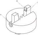
Fig. 1 is a schematic view of the overall structure of the jig device of the present invention.
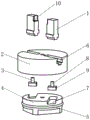
Fig. 2 is an exploded view of the jig device of the present invention.
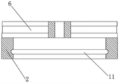
Fig. 3 is a schematic longitudinal sectional view of the cylindrical upper turntable of the present invention.
In the figure: 1. v type centering piece, 2, cylindrical carousel on, 3, slider, 4, lower carousel, 5, marginal jut, 6, T type guide way, 7, linear type guide way, 8, cylindrical support portion, 9, rectangle rotating part, 10, V type recess, 11, mounting groove.
Detailed Description
As shown in fig. 1, 2 and 3, a jig device for intelligently detecting the center thickness of a lens selects a wear-resistant material to prolong the service life and ensure the accuracy for a long time. The jig device comprises a cylindrical upper rotary table 2, a lower rotary table 4, a sliding block 3 and a V-shaped centering block 1 for lens centering, wherein the V-shaped centering block 1 is provided with a V-shaped groove 10 matched with a lens.
The inner surface of the cylindrical upper rotary table is provided with a circle of mounting grooves 11, and the outer surface of the lower rotary table 4 is provided with edge protrusions 5 which are in transition fit with the inner surface mounting grooves 11 of the cylindrical upper rotary table 2, so that the cylindrical upper rotary table 2 and the lower rotary table 4 can be reliably fixed and can rotate mutually.
The cylindrical upper turntable 2 is of a hollow shell type structure. Two T type guide ways 6 with V type centering block 1 matched with are seted up to cylindrical upper surface of going up carousel 2, and two T type guide ways 6 are central symmetry structure, and T type guide way 6 is arranged in to the lower surface of V type centering block 1. The T-shaped guide groove 6 can guarantee that the clamping v-shaped centering blocks 1 move linearly in the T-shaped guide groove 6, and meanwhile, the two v-shaped centering blocks 1 can be guaranteed to move for the same distance in opposite directions simultaneously, so that the centering accuracy of the clamped optical lens is guaranteed.
Two linear type guide grooves 7 which are parallel to each other are formed in the upper surface of the lower rotating disc 4, and the motion of the sliding block 3 is guided.
The cylindrical support part 8 and the centering v-shaped centering block 1 are detachably connected with high relative position precision; one advantage of this kind of connected mode is, when the great wearing and tearing of influence appear in v type centering piece 1 or cylindrical support portion 8, can be comparatively convenient change, save the cost.
When the lower rotary table 4 rotates, the linear motion of the sliding block 3 is converted into the linear motion of the v-shaped centering block 1 through the guiding action of the T-shaped guide groove 6, and the v-shaped centering block 1 finally moves towards the center or outwards at the same speed. The v-shaped centering block 1 has a centering function, and when the contact type measurement is carried out, a contact point is accurately positioned at the central part of the lens, and certain lens edge constraint is provided, so that the lens is prevented from shaking in the measurement process, and the measurement precision is ensured.
Aiming at the clamp device for intelligently detecting the center thickness of the lens, the corresponding detection method comprises the following operation steps:
1) before the measurement is started, the device clamping accuracy is first detected.
The specific process comprises the following steps: putting the lens with the standard thickness into a jig device, rotating a lower turntable 4 to enable a V-shaped centering block 1 to approach the lens until the lens is clamped, then moving an upper measuring probe and a lower measuring probe, stopping moving when the upper measuring probe and the lower measuring probe are respectively contacted with the lens, measuring the center thickness of the lens of the standard sample piece, comparing the obtained value with a standard value, and if the error is within an allowable range, indicating that the clamping precision of the clamp meets the requirement, and continuing the test;
2) putting a lens to be measured into a jig device, driving the cylindrical upper rotary table 2 and the cylindrical lower rotary table 4 to rotate relatively by a motor, driving the sliding block 3 to do linear motion in the linear guide groove 7 at the moment, and driving the v-shaped centering block 1 to approach to the center along the linear guide groove 7 through the matching of the cylindrical supporting part 8 to finish centering and tightening of the lens;
3) the upper and lower measuring probes move until the upper and lower surfaces of the lens are contacted with each other, the central thickness of the lens is measured and fed back to the sensor, and data are uploaded;
4) after the measurement is finished, the upper and lower measuring probes and the v-shaped centering block 1 are reset, the lens is taken down, and the next measurement is waited.
Claims (9)
Priority Applications (1)
| Application Number | Priority Date | Filing Date | Title |
|---|---|---|---|
| CN202011265515.6A CN112254690A (en) | 2020-11-13 | 2020-11-13 | A jig device and detection method for intelligently detecting the thickness of the center of the lens |
Applications Claiming Priority (1)
| Application Number | Priority Date | Filing Date | Title |
|---|---|---|---|
| CN202011265515.6A CN112254690A (en) | 2020-11-13 | 2020-11-13 | A jig device and detection method for intelligently detecting the thickness of the center of the lens |
Publications (1)
| Publication Number | Publication Date |
|---|---|
| CN112254690A true CN112254690A (en) | 2021-01-22 |
Family
ID=74266903
Family Applications (1)
| Application Number | Title | Priority Date | Filing Date |
|---|---|---|---|
| CN202011265515.6A Pending CN112254690A (en) | 2020-11-13 | 2020-11-13 | A jig device and detection method for intelligently detecting the thickness of the center of the lens |
Country Status (1)
| Country | Link |
|---|---|
| CN (1) | CN112254690A (en) |
Cited By (1)
| Publication number | Priority date | Publication date | Assignee | Title |
|---|---|---|---|---|
| CN114046730A (en) * | 2021-10-29 | 2022-02-15 | 南京茂莱光学科技股份有限公司 | Optical lens auxiliary jig and method for measuring surface type precision and R value deviation thereof |
Citations (6)
| Publication number | Priority date | Publication date | Assignee | Title |
|---|---|---|---|---|
| CN102506751A (en) * | 2011-10-31 | 2012-06-20 | 中国科学院长春光学精密机械与物理研究所 | Self-centering clamp for detecting optical element |
| CN104613881A (en) * | 2015-02-12 | 2015-05-13 | 江苏宇迪光学股份有限公司 | Lens center thickness measuring device and method based on double face confocal measurement |
| CN204524880U (en) * | 2015-01-05 | 2015-08-05 | 沈阳工学院 | A kind of V-block self-centering apparatus |
| CN205763962U (en) * | 2016-07-06 | 2016-12-07 | 衢州启程机械设备有限公司 | A kind of scroll chuck that can realize Quick-clamped |
| CN111804942A (en) * | 2020-06-24 | 2020-10-23 | 英诺莱比(北京)科技有限公司 | Center-sharing clamping tool |
| CN213600041U (en) * | 2020-11-13 | 2021-07-02 | 江苏宇迪光学股份有限公司 | A jig device for intelligently detecting the thickness of the center of the lens |
-
2020
- 2020-11-13 CN CN202011265515.6A patent/CN112254690A/en active Pending
Patent Citations (6)
| Publication number | Priority date | Publication date | Assignee | Title |
|---|---|---|---|---|
| CN102506751A (en) * | 2011-10-31 | 2012-06-20 | 中国科学院长春光学精密机械与物理研究所 | Self-centering clamp for detecting optical element |
| CN204524880U (en) * | 2015-01-05 | 2015-08-05 | 沈阳工学院 | A kind of V-block self-centering apparatus |
| CN104613881A (en) * | 2015-02-12 | 2015-05-13 | 江苏宇迪光学股份有限公司 | Lens center thickness measuring device and method based on double face confocal measurement |
| CN205763962U (en) * | 2016-07-06 | 2016-12-07 | 衢州启程机械设备有限公司 | A kind of scroll chuck that can realize Quick-clamped |
| CN111804942A (en) * | 2020-06-24 | 2020-10-23 | 英诺莱比(北京)科技有限公司 | Center-sharing clamping tool |
| CN213600041U (en) * | 2020-11-13 | 2021-07-02 | 江苏宇迪光学股份有限公司 | A jig device for intelligently detecting the thickness of the center of the lens |
Non-Patent Citations (1)
| Title |
|---|
| 徐凤英,张增学: "车工", 30 September 2004, 广东科技出版社, pages: 50 - 63 * |
Cited By (2)
| Publication number | Priority date | Publication date | Assignee | Title |
|---|---|---|---|---|
| CN114046730A (en) * | 2021-10-29 | 2022-02-15 | 南京茂莱光学科技股份有限公司 | Optical lens auxiliary jig and method for measuring surface type precision and R value deviation thereof |
| CN114046730B (en) * | 2021-10-29 | 2023-01-24 | 南京茂莱光学科技股份有限公司 | Optical lens auxiliary jig and measuring method of surface type precision and R value deviation thereof |
Similar Documents
| Publication | Publication Date | Title |
|---|---|---|
| CN104515493B (en) | Automatic radial run-out measuring device | |
| WO2016150005A1 (en) | Automatic detection method and apparatus for digital caliper | |
| CN103557813B (en) | The on-line measuring device of axial workpiece | |
| CN213600041U (en) | A jig device for intelligently detecting the thickness of the center of the lens | |
| CN117260389A (en) | Multi-sensor fusion-driven large-scale deep hole part shape error in-situ measurement system | |
| CN112254690A (en) | A jig device and detection method for intelligently detecting the thickness of the center of the lens | |
| CN112444178B (en) | A Universal Fixture for Detecting Lens Thickness | |
| CN210719022U (en) | Full-size measuring equipment for watch case | |
| CN209745191U (en) | Detection device for hole and shaft belt pin | |
| CN220206711U (en) | Vertical line coordinatometer calibration device | |
| CN111678483B (en) | A Servo Motor Driven Inner Diameter Measuring Device | |
| CN103868469A (en) | Full automatic following tracking precise scanning detecting device and method for camshaft complex molded-line lift | |
| CN113804137B (en) | A rapid nondestructive testing device for annular forgings and castings | |
| CN216067155U (en) | Bearing ring detection device with synchronous positioning function | |
| CN207344264U (en) | Cylinder zooms cam machining precision detection device | |
| CN216049625U (en) | Device for accurately detecting parallelism and verticality of end base surfaces of multiple groups of holes | |
| CN209927068U (en) | Tool for measuring concentricity | |
| CN220541928U (en) | Cylinder sleeve diameter measuring device | |
| CN113829270A (en) | Bearing ring detection device with synchronous positioning function and detection method | |
| CN209131567U (en) | A non-full-shaped outer circle detection device | |
| CN209355863U (en) | Hole size measuring device | |
| CN107356188A (en) | A kind of displacement transducer marking apparatus | |
| CN110307794B (en) | High-precision intelligent aperture testing device and testing method | |
| CN108317940B (en) | Device and method for detecting side lug angle of cylindrical workpiece | |
| CN112050703A (en) | Automatic detection equipment for jump degree of chuck |
Legal Events
| Date | Code | Title | Description |
|---|---|---|---|
| PB01 | Publication | ||
| PB01 | Publication | ||
| SE01 | Entry into force of request for substantive examination | ||
| SE01 | Entry into force of request for substantive examination |