CN1122273C - Data decoding system and method, transfer device and method, and receiving device and method - Google Patents
Data decoding system and method, transfer device and method, and receiving device and method Download PDFInfo
- Publication number
- CN1122273C CN1122273C CN97126017A CN97126017A CN1122273C CN 1122273 C CN1122273 C CN 1122273C CN 97126017 A CN97126017 A CN 97126017A CN 97126017 A CN97126017 A CN 97126017A CN 1122273 C CN1122273 C CN 1122273C
- Authority
- CN
- China
- Prior art keywords
- data
- equipment
- impact damper
- temporary
- audio
- Prior art date
- Legal status (The legal status is an assumption and is not a legal conclusion. Google has not performed a legal analysis and makes no representation as to the accuracy of the status listed.)
- Expired - Fee Related
Links
- 238000000034 method Methods 0.000 title claims description 45
- 238000012546 transfer Methods 0.000 title claims description 33
- 238000006243 chemical reaction Methods 0.000 claims description 18
- 238000013459 approach Methods 0.000 claims description 12
- 230000005540 biological transmission Effects 0.000 abstract description 43
- 230000006854 communication Effects 0.000 description 24
- 238000004891 communication Methods 0.000 description 23
- 230000001360 synchronised effect Effects 0.000 description 17
- 239000000872 buffer Substances 0.000 description 12
- 230000003287 optical effect Effects 0.000 description 8
- 230000005236 sound signal Effects 0.000 description 8
- 238000000926 separation method Methods 0.000 description 5
- 241001269238 Data Species 0.000 description 4
- 238000003780 insertion Methods 0.000 description 4
- 230000037431 insertion Effects 0.000 description 4
- 230000008030 elimination Effects 0.000 description 3
- 238000003379 elimination reaction Methods 0.000 description 3
- 238000012545 processing Methods 0.000 description 3
- 238000012360 testing method Methods 0.000 description 3
- 238000001514 detection method Methods 0.000 description 2
- 241001672694 Citrus reticulata Species 0.000 description 1
- 230000006978 adaptation Effects 0.000 description 1
- 230000033228 biological regulation Effects 0.000 description 1
- 230000006835 compression Effects 0.000 description 1
- 238000007906 compression Methods 0.000 description 1
- 238000000354 decomposition reaction Methods 0.000 description 1
- 230000007423 decrease Effects 0.000 description 1
- 235000013399 edible fruits Nutrition 0.000 description 1
- 238000005516 engineering process Methods 0.000 description 1
Images


Classifications
-
- H—ELECTRICITY
- H04—ELECTRIC COMMUNICATION TECHNIQUE
- H04L—TRANSMISSION OF DIGITAL INFORMATION, e.g. TELEGRAPHIC COMMUNICATION
- H04L12/00—Data switching networks
- H04L12/28—Data switching networks characterised by path configuration, e.g. LAN [Local Area Networks] or WAN [Wide Area Networks]
- H04L12/40—Bus networks
- H04L12/40052—High-speed IEEE 1394 serial bus
- H04L12/40058—Isochronous transmission
-
- H—ELECTRICITY
- H04—ELECTRIC COMMUNICATION TECHNIQUE
- H04N—PICTORIAL COMMUNICATION, e.g. TELEVISION
- H04N21/00—Selective content distribution, e.g. interactive television or video on demand [VOD]
- H04N21/40—Client devices specifically adapted for the reception of or interaction with content, e.g. set-top-box [STB]; Operations thereof
- H04N21/43—Processing of content or additional data, e.g. demultiplexing additional data from a digital video stream; Elementary client operations, e.g. monitoring of home network or synchronising decoder's clock; Client middleware
- H04N21/434—Disassembling of a multiplex stream, e.g. demultiplexing audio and video streams, extraction of additional data from a video stream; Remultiplexing of multiplex streams; Extraction or processing of SI; Disassembling of packetised elementary stream
-
- G—PHYSICS
- G11—INFORMATION STORAGE
- G11B—INFORMATION STORAGE BASED ON RELATIVE MOVEMENT BETWEEN RECORD CARRIER AND TRANSDUCER
- G11B27/00—Editing; Indexing; Addressing; Timing or synchronising; Monitoring; Measuring tape travel
- G11B27/10—Indexing; Addressing; Timing or synchronising; Measuring tape travel
- G11B27/102—Programmed access in sequence to addressed parts of tracks of operating record carriers
- G11B27/105—Programmed access in sequence to addressed parts of tracks of operating record carriers of operating discs
-
- G—PHYSICS
- G11—INFORMATION STORAGE
- G11B—INFORMATION STORAGE BASED ON RELATIVE MOVEMENT BETWEEN RECORD CARRIER AND TRANSDUCER
- G11B27/00—Editing; Indexing; Addressing; Timing or synchronising; Monitoring; Measuring tape travel
- G11B27/10—Indexing; Addressing; Timing or synchronising; Measuring tape travel
- G11B27/19—Indexing; Addressing; Timing or synchronising; Measuring tape travel by using information detectable on the record carrier
- G11B27/28—Indexing; Addressing; Timing or synchronising; Measuring tape travel by using information detectable on the record carrier by using information signals recorded by the same method as the main recording
- G11B27/30—Indexing; Addressing; Timing or synchronising; Measuring tape travel by using information detectable on the record carrier by using information signals recorded by the same method as the main recording on the same track as the main recording
- G11B27/3027—Indexing; Addressing; Timing or synchronising; Measuring tape travel by using information detectable on the record carrier by using information signals recorded by the same method as the main recording on the same track as the main recording used signal is digitally coded
-
- H—ELECTRICITY
- H04—ELECTRIC COMMUNICATION TECHNIQUE
- H04L—TRANSMISSION OF DIGITAL INFORMATION, e.g. TELEGRAPHIC COMMUNICATION
- H04L12/00—Data switching networks
- H04L12/28—Data switching networks characterised by path configuration, e.g. LAN [Local Area Networks] or WAN [Wide Area Networks]
- H04L12/40—Bus networks
- H04L12/40052—High-speed IEEE 1394 serial bus
- H04L12/40117—Interconnection of audio or video/imaging devices
-
- H—ELECTRICITY
- H04—ELECTRIC COMMUNICATION TECHNIQUE
- H04N—PICTORIAL COMMUNICATION, e.g. TELEVISION
- H04N21/00—Selective content distribution, e.g. interactive television or video on demand [VOD]
- H04N21/20—Servers specifically adapted for the distribution of content, e.g. VOD servers; Operations thereof
- H04N21/25—Management operations performed by the server for facilitating the content distribution or administrating data related to end-users or client devices, e.g. end-user or client device authentication, learning user preferences for recommending movies
- H04N21/266—Channel or content management, e.g. generation and management of keys and entitlement messages in a conditional access system, merging a VOD unicast channel into a multicast channel
- H04N21/2662—Controlling the complexity of the video stream, e.g. by scaling the resolution or bitrate of the video stream based on the client capabilities
-
- H—ELECTRICITY
- H04—ELECTRIC COMMUNICATION TECHNIQUE
- H04N—PICTORIAL COMMUNICATION, e.g. TELEVISION
- H04N21/00—Selective content distribution, e.g. interactive television or video on demand [VOD]
- H04N21/40—Client devices specifically adapted for the reception of or interaction with content, e.g. set-top-box [STB]; Operations thereof
- H04N21/41—Structure of client; Structure of client peripherals
- H04N21/414—Specialised client platforms, e.g. receiver in car or embedded in a mobile appliance
- H04N21/4147—PVR [Personal Video Recorder]
-
- H—ELECTRICITY
- H04—ELECTRIC COMMUNICATION TECHNIQUE
- H04N—PICTORIAL COMMUNICATION, e.g. TELEVISION
- H04N21/00—Selective content distribution, e.g. interactive television or video on demand [VOD]
- H04N21/40—Client devices specifically adapted for the reception of or interaction with content, e.g. set-top-box [STB]; Operations thereof
- H04N21/41—Structure of client; Structure of client peripherals
- H04N21/426—Internal components of the client ; Characteristics thereof
-
- H—ELECTRICITY
- H04—ELECTRIC COMMUNICATION TECHNIQUE
- H04N—PICTORIAL COMMUNICATION, e.g. TELEVISION
- H04N21/00—Selective content distribution, e.g. interactive television or video on demand [VOD]
- H04N21/40—Client devices specifically adapted for the reception of or interaction with content, e.g. set-top-box [STB]; Operations thereof
- H04N21/43—Processing of content or additional data, e.g. demultiplexing additional data from a digital video stream; Elementary client operations, e.g. monitoring of home network or synchronising decoder's clock; Client middleware
- H04N21/434—Disassembling of a multiplex stream, e.g. demultiplexing audio and video streams, extraction of additional data from a video stream; Remultiplexing of multiplex streams; Extraction or processing of SI; Disassembling of packetised elementary stream
- H04N21/4341—Demultiplexing of audio and video streams
-
- H—ELECTRICITY
- H04—ELECTRIC COMMUNICATION TECHNIQUE
- H04N—PICTORIAL COMMUNICATION, e.g. TELEVISION
- H04N21/00—Selective content distribution, e.g. interactive television or video on demand [VOD]
- H04N21/40—Client devices specifically adapted for the reception of or interaction with content, e.g. set-top-box [STB]; Operations thereof
- H04N21/43—Processing of content or additional data, e.g. demultiplexing additional data from a digital video stream; Elementary client operations, e.g. monitoring of home network or synchronising decoder's clock; Client middleware
- H04N21/436—Interfacing a local distribution network, e.g. communicating with another STB or one or more peripheral devices inside the home
- H04N21/4363—Adapting the video stream to a specific local network, e.g. a Bluetooth® network
- H04N21/43632—Adapting the video stream to a specific local network, e.g. a Bluetooth® network involving a wired protocol, e.g. IEEE 1394
-
- H—ELECTRICITY
- H04—ELECTRIC COMMUNICATION TECHNIQUE
- H04N—PICTORIAL COMMUNICATION, e.g. TELEVISION
- H04N21/00—Selective content distribution, e.g. interactive television or video on demand [VOD]
- H04N21/40—Client devices specifically adapted for the reception of or interaction with content, e.g. set-top-box [STB]; Operations thereof
- H04N21/43—Processing of content or additional data, e.g. demultiplexing additional data from a digital video stream; Elementary client operations, e.g. monitoring of home network or synchronising decoder's clock; Client middleware
- H04N21/44—Processing of video elementary streams, e.g. splicing a video clip retrieved from local storage with an incoming video stream or rendering scenes according to encoded video stream scene graphs
- H04N21/4402—Processing of video elementary streams, e.g. splicing a video clip retrieved from local storage with an incoming video stream or rendering scenes according to encoded video stream scene graphs involving reformatting operations of video signals for household redistribution, storage or real-time display
-
- H—ELECTRICITY
- H04—ELECTRIC COMMUNICATION TECHNIQUE
- H04N—PICTORIAL COMMUNICATION, e.g. TELEVISION
- H04N21/00—Selective content distribution, e.g. interactive television or video on demand [VOD]
- H04N21/40—Client devices specifically adapted for the reception of or interaction with content, e.g. set-top-box [STB]; Operations thereof
- H04N21/47—End-user applications
- H04N21/485—End-user interface for client configuration
- H04N21/4856—End-user interface for client configuration for language selection, e.g. for the menu or subtitles
-
- H—ELECTRICITY
- H04—ELECTRIC COMMUNICATION TECHNIQUE
- H04N—PICTORIAL COMMUNICATION, e.g. TELEVISION
- H04N9/00—Details of colour television systems
- H04N9/79—Processing of colour television signals in connection with recording
- H04N9/80—Transformation of the television signal for recording, e.g. modulation, frequency changing; Inverse transformation for playback
- H04N9/804—Transformation of the television signal for recording, e.g. modulation, frequency changing; Inverse transformation for playback involving pulse code modulation of the colour picture signal components
- H04N9/8042—Transformation of the television signal for recording, e.g. modulation, frequency changing; Inverse transformation for playback involving pulse code modulation of the colour picture signal components involving data reduction
-
- G—PHYSICS
- G11—INFORMATION STORAGE
- G11B—INFORMATION STORAGE BASED ON RELATIVE MOVEMENT BETWEEN RECORD CARRIER AND TRANSDUCER
- G11B2220/00—Record carriers by type
- G11B2220/20—Disc-shaped record carriers
- G11B2220/25—Disc-shaped record carriers characterised in that the disc is based on a specific recording technology
- G11B2220/2537—Optical discs
- G11B2220/2562—DVDs [digital versatile discs]; Digital video discs; MMCDs; HDCDs
-
- H—ELECTRICITY
- H04—ELECTRIC COMMUNICATION TECHNIQUE
- H04N—PICTORIAL COMMUNICATION, e.g. TELEVISION
- H04N5/00—Details of television systems
- H04N5/04—Synchronising
-
- H—ELECTRICITY
- H04—ELECTRIC COMMUNICATION TECHNIQUE
- H04N—PICTORIAL COMMUNICATION, e.g. TELEVISION
- H04N5/00—Details of television systems
- H04N5/76—Television signal recording
- H04N5/84—Television signal recording using optical recording
- H04N5/85—Television signal recording using optical recording on discs or drums
-
- H—ELECTRICITY
- H04—ELECTRIC COMMUNICATION TECHNIQUE
- H04N—PICTORIAL COMMUNICATION, e.g. TELEVISION
- H04N9/00—Details of colour television systems
- H04N9/79—Processing of colour television signals in connection with recording
- H04N9/80—Transformation of the television signal for recording, e.g. modulation, frequency changing; Inverse transformation for playback
- H04N9/82—Transformation of the television signal for recording, e.g. modulation, frequency changing; Inverse transformation for playback the individual colour picture signal components being recorded simultaneously only
- H04N9/8205—Transformation of the television signal for recording, e.g. modulation, frequency changing; Inverse transformation for playback the individual colour picture signal components being recorded simultaneously only involving the multiplexing of an additional signal and the colour video signal
Landscapes
- Engineering & Computer Science (AREA)
- Signal Processing (AREA)
- Multimedia (AREA)
- Computer Networks & Wireless Communication (AREA)
- Human Computer Interaction (AREA)
- Databases & Information Systems (AREA)
- Signal Processing For Digital Recording And Reproducing (AREA)
- Television Signal Processing For Recording (AREA)
- Compression Or Coding Systems Of Tv Signals (AREA)
- Compression, Expansion, Code Conversion, And Decoders (AREA)
- Time-Division Multiplex Systems (AREA)
- Two-Way Televisions, Distribution Of Moving Picture Or The Like (AREA)
Abstract
Data that is an MPEG program stream (PS) read out from a disc is supplied to a PS/TS converter via a variable rate control section. The PS/TS converter converts the PS MPEG data into a transport stream (TS) and transmits it to a presentation device via a 1394 transmission/reception section. Data received by a 1394 transmission/reception section of the presentation device is classified by a DEMUX section. An audio decoder and a video decoder decode the TS MPEG data. D/A converters convert resulting digital data into analog signals and output the analog signals.
Description
Technical field
The present invention relates to data encoding system and method, conveyer and method and receiving trap and method.Be particularly related to when utilizing digital interface to transmit data, a kind of data mode be transformed to data encoding system and method, conveyer and method and the receiving trap and the method for the form that is suitable for the receiver side code translator at transmission or receiver side.
Background technology
DVD (digital universal disc) video (hereinafter to be referred as " DVD ") expects now that recently by standardization it uses widely.Video data compresses according to MPEG (Motion Picture Experts Group) scheme and is recorded on the DVD.In DVD player, play the DVD driven portion, reproduces the decoded part of data and decipher.The data that obtain are exported to television receiver etc., and show the image corresponding to these data thereon.
The DVD data that meet the MPEG scheme are carried out record as program stream, the program that this program stream is made up of video information, audio-frequency information and related data.
Fig. 1 represents an exemplary architecture of DVD player.
In DVD player 1, in the data of reading from dish (DVD) 101, the expression data of being made up of video data, voice data and the sub-image data relevant with voice data with this video (by being compressed into program stream according to the MPEG scheme) are provided for expression engine 12.This expression engine 12 reproduces these data and the data that obtain is exported to display etc.
On the other hand, be provided for boot manager 11 from the vectoring information of coiling reproduction order, behavior and other item that read 101, the regulation reproduction period.This boot manager 11 is according to the data reproduction in this vectoring information control expression engine 12.
The signal of controlling and being provided by the setter (not shown) corresponding to the user also is provided boot manager 11, and carries out corresponding to this signal, promptly corresponding to this user's the processing of controlling.
For example, when the user controls when reproducing audio selection key (not shown) and coming that voice language changed into English from communicating with the eyes, just be provided for boot manager 11 corresponding to this signal of controlling.This boot manager 11 just from expression the vectoring information stream number and the table of the relation between the sub-ID in read stream number corresponding to the sub-ID of English sound, and resulting information is exported to expression engine 12.In case receive this information, expression engine 12 is just changed into language English and is exported corresponding voice data from Japanese.
Fig. 2 represents an exemplary architecture of boot manager 11.
General control data is from coiling the part of the vectoring information that is read out 101, being provided for general control section 21.General control data comprises the general information of stream, and for example the type of the type of compress mode, broadcasting scheme (NTSC, PAL etc.) also comprises father's information.
The inlet search data that also is the part of vectoring information is provided for inlet search part 22.The inlet search data comprises an address table, on this address table indicating panel 101 record expression wait to reproduce data the reproduction step PGCI (program chain information) and represent the position of data.
The user interface control data that also is the part of vectoring information is provided for user interface control section 24.The user interface control data is to stipulate that according to reproducing the position controlling of user allows or the data of forbidding.
When controlling of user was allowed to, user interface control section 24 was just sending a given circuit (not shown) to corresponding to a signal of controlling.
The guiding control data that also is the part of vectoring information is PGCI, is provided for guiding control section 23.
When boot manager 11 was handled vectoring information in the manner described above, expression engine 12 was operated according to being recorded in the setting of coiling on 101.
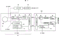
Fig. 3 provides an exemplary architecture of expression engine 12.
DEMUX (multichannel decomposition) part 31 is according to the stream ID in the bag head that is written into the expression data, being divided into audio pack, video packets and sub-picture pack from coiling the 101 expression data of reading, and, these data (bag) are exported to tone decoder 32, video decoder 33 and subimage code translator 34 respectively according to the type of data.
The data that provided are provided respectively for tone decoder 32, video decoder 33 and subimage code translator 34, and decoded signal is exported to D/A transducer 41 or supercircuit 36.
Highlighted code translator 35 is specified highlighted position and color according to the highlighted information that boot manager 11 provides, and highlighted image is exported to supercircuit 36.
The highlighted image that the video image that supercircuit 36 overlay video code translators 33 provide, the subimage (captions etc.) that subimage code translator 34 provides and highlighted code translator 35 provide, and superimposed image exported to D/A transducer 42.
D/A transducer 41 and 42 is the digital signal conversion that is provided a simulating signal respectively, output analogue audio frequency and vision signal.
As mentioned above, when DVD playing back, except that the expression data, also vectoring information is handled.
On the other hand, in the device that receives digital satellite broadcasting, the mpeg data that broadcasting satellite sends is received and deciphers by built-in code translator, and demonstration or output are corresponding to the images/information and the sound of decoding data.Because mpeg data sends with the form of the transport stream be made up of a plurality of programs, so this device has the code translator that is suitable for handling transport stream.
But, such problem is arranged, promptly ought attempt to utilize device with the code translator that is suitable for handling transport stream, before decoding, the data (mpeg data) of DVD are handled and show or when exporting image corresponding to decoding data etc. as above-mentioned device, because the difference of data mode (being program stream or transport stream), it is difficult that the data that received are handled.
Summary of the invention
In view of above situation has proposed the present invention.Therefore, the objective of the invention is when utilizing digital interface to send data, by data mode being transformed to the form of the code translator that is suitable for receiving a side sending a side (DVD player) or receive a side (device), and make device can reproduce the data that are recorded on the DVD with the code translator that is suitable for handling transport stream with the code translator that is suitable for handling transport stream.
In data encoding system of the present invention, first equipment or second equipment comprise the converting means that the first form data is transformed to the second form data; Described second equipment comprises code translator, and this device is used to decipher the described second form data.
In data decoding method of the present invention, first equipment is transformed to the second form data to the first form data, sends the second form data then, and perhaps second equipment receives the first form data and it is transformed to the second form data; Second equipment is deciphered the second form data.
Data encoding system of the present invention comprises: reproduce first equipment that is recorded in the data on the given recording medium and utilizes IEEE1394 interface transmission reproduction data; And reception is carried out a plurality of second equipment that digital-analog conversion is exported simulating signal via the data of IEEE1394 interface transmission and to receiving data.
Transfer equipment of the present invention comprises: the converting means that the first form data is transformed to the second form data that are the data mode in the code translator; And the conveyer that transmits the second form data.
Transfer approach of the present invention may further comprise the steps: it is the second form data of the data mode in the code translator that the first form data are transformed to; And transmit the second form data.
Receiving equipment of the present invention comprises: the receiving trap that receives the first form data; The first form data are transformed to the converting means of the second form data that are the data mode in the code translator; And the code translator of deciphering the second form data.
Method of reseptance of the present invention may further comprise the steps: receive the first form data; It is the second form data of the data mode in the code translator that the first form data are transformed to; And decipher the second form data.
Receiving equipment of the present invention comprises: first code translator of deciphering the first form data; Decipher second code translator of the second form data; And receive the first or second form data and receive the feedway that data offer first code translator or second code translator according to the form handle that receives data.
Method of reseptance of the present invention may further comprise the steps: receive the first form data or the second form data and offer the first decoding part or the second decoding part according to the form that receives data receiving data; The decoding first form data in the first decoding part; And in the second decoding part, decipher the second form data.
In data encoding system of the present invention, the converting means that is arranged in first or second equipment is transformed to the second form data to the first form data, and second equipment is deciphered the second form data.
In data decoding method of the present invention, first equipment is transformed to the concurrent second form data of sending of the second form data to the first form data, perhaps second equipment receives the first form data and it is transformed to the second form data, and second equipment is deciphered the second form data.
In data encoding system of the present invention, first equipment reproduces and is recorded in the data on the given recording medium and utilizes the transmission of IEEE1394 interface to reproduce data, and a plurality of second equipment receive via the data of IEEE1394 transmission and to receiving data execution digital-analog conversion and export simulating signal.
In transfer equipment of the present invention, it is second form data of the data mode in the code translator that converting means is transformed to the first form data, and conveyer transmits the second form data.
In transfer approach of the present invention, it is the second form data of the data mode in the code translator that the first form data are transformed to, and transmits the second form data.
In receiving equipment of the present invention, receiving trap receives the first form data, and it is second form data of the data mode in the code translator that converting means is transformed to the first form data, and code translator is deciphered the second form data.
In method of reseptance of the present invention, receive the first form data, it is the second form data of the data mode in the code translator that the first form data are transformed to, and deciphers the second form data.
In receiving equipment of the present invention, feedway receives the first form data or the second form data and offers first code translator or second code translator according to the form that receives data, first code translator is deciphered the first form data, and second code translator is deciphered the second form data.
In method of reseptance of the present invention, receive the first form data or the second form data and offer the first decoding part or the second decoding part receiving data according to the form that receives data.The decoding first form data in the first decoding part, the decoding second form data in the second decoding part.
Description of drawings
Fig. 1 is the block scheme of an exemplary architecture of expression DVD player 1;
Fig. 2 represents the exemplary architecture of boot manager 11 shown in Figure 1;
Fig. 3 represents the exemplary architecture of expression engine 12 shown in Figure 1;
Fig. 4 is the block scheme of exemplary architecture that an AV system of data encoding system of the present invention has been adopted in expression;
Fig. 5 is the block scheme of inner structure of first embodiment of expression DVD player 61 shown in Figure 4 and indication equipment 63-1;
Fig. 6 represents the pack arrangement of synchronous communication;
Fig. 7 represents the command format of CIP head;
Fig. 8 represents the order of asynchronous communication and the structure of respond packet;
Fig. 9 A and 9B represent the form of asynchronous communication;
Figure 10 schematically shows synchronous communication;
Figure 11 represents an example of packet format;
Figure 12 represents to flow an example of correlativity between ID value and the bag type;
Figure 13 represents an example of correlativity between son stream ID value and the bag type;
Figure 14 is the block scheme of inner structure of second embodiment of expression DVD player 61 shown in Figure 4 and indication equipment 63-1;
Figure 15 is the block scheme of inner structure of the 3rd embodiment of expression DVD player 61 shown in Figure 4 and indication equipment 63-1;
Figure 16 is the block scheme of inner structure of the 4th embodiment of expression DVD player 61 shown in Figure 4 and indication equipment 63-1;
Figure 17 represents transport stream system target code translator model;
Figure 18 is the block scheme of inner structure of the 5th embodiment of expression DVD player 61 shown in Figure 4 and indication equipment 63-1;
Figure 19 is the block scheme of the exemplary architecture of expression PS/TS transducer 171;
Figure 20 represents to wrap the example of the content of head;
Figure 21 represents the example of the PID of DVD.
Embodiment
Fig. 4 has represented to adopt the exemplary architecture of an AV system of data encoding system of the present invention.In this AV system, DVD player 61 DVD playing back are also exported analog video signal and are given a simulated television receiver 62, and the latter shows the image corresponding to received signal.
(last set top box (set-top-box, the STB)) 63-1 to 63-3 that for example is used for digital satellite broadcasting is connected with DVD player 61 by AV bus 64 a plurality of (being 3 in this example) indication equipment.
The coding video frequency data that indication equipment 63-1 to 63-3 decoding DVD player 61 transmits by AV bus 64.
For example, AV bus 64 is the buses by IEEE (Institute of Electrical and Electric Engineers) 1394 high performance bus standard codes.
Fig. 5 represents the DVD player 61 of first embodiment and the inner structure of indication equipment 63-1.Though not shown in Fig. 5, the structure of indication equipment 63-2 and 63-3 is identical with indication equipment 63-1's.
In the DVD player 61 of Fig. 5, disk drive is transmitted to expression engine 12 and variable bit rate control section (VBR control section) 72 from the expression data of coiling 101 mpeg program streams of reading, and vectoring information is transmitted boot manager 11.
Variable bit rate control section 72 is exported to sub-DEMUX part 73 according to such timing transmitting data, that is, make indication equipment 63-1 can decipher the reception data immediately.For example, assignee of the present invention's the disclosed variable bit rate control section of the flat 8-238781 of Japanese patent application No. can be used as variable bit rate control section 72.
ISO/IEC 13818-1 (version in 1996) has stipulated program stream (PS) and the transport stream (TS) as the form of MPEG2.
By the digital signal of multiplex video data, voice data and additional information data, when each is predetermined/minute form a bag and constitute program stream.The length of each bag is variable, and its size can change according to size of data.Therefore, each bag has different sizes.For example, can be by this pre-sets and constitutes program stream in the bag of 2K byte that above data are packed into.In this case, if data greater than the 2K byte, are just put into next bag to remainder.If the zone that is not used is arranged, just add the bag that fill area constitutes a 2K byte.
On the contrary, the bag of transport stream has fixing length (size).For example, come like this to determine content, make that each audio pack and each video packets all are 188 bytes, constitute transport stream along time-axis direction arrangement audio pack and video packets.Because in general video data have the length bigger than voice data, so transport stream for example is made up of a group that comprises 10 video packets, an audio pack and an additional information bag (12 bags) totally.
Therefore, PS to TS conversion can be finished like this, promptly sequentially elongated PS bag is divided into video packets, audio pack and additional information bag, makes them have the regular length (for example 188 bytes) of TS bag, and arranges these bags along time-axis direction.In this case, add all kinds head and satisfy the TS packet format.
When the dish of the voice data of Japanese, English, French and four kinds of language of Chinese had for example been write down in broadcast, the bag that is recorded in the whole language on the dish 101 sent sub-DEMUX part 73 to by variable bit rate control section 72.Therefore, when for example Japanese was selected language, sub-DEMUX part 73 was just left out unnecessary bag (being English, French and Chinese bag in this example) and is reduced volume of transmitted data.
The mpeg data of the program stream that PS/TS transducer 74 bundle DEMUX parts 73 provide is transformed to the mpeg data of the transport stream that is exported to 1394 transmission/receiving units 75 (transmitting device).
1394 transmission/receiving units 75 are carried out the synchronous communication process according to the IEEE1394 standard, the data that obtain are sent to transmission/receiving unit 91 (receiving trap) of indication equipment 63-1.
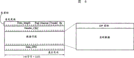
Fig. 6 represents the pack arrangement of synchronous communication.The synchronous communication bag is made up of bag head, head CRC, data field and data CRC.
The bag head comprises: " the Data length " of expression data length, expression is by " Tag " of the Format Type of the data of relevant bag transmission, " Channel " of the number of channel of expression bag one of (0 to 63), " Tcode " of expression process code, and by the synchronous code " Sy " of each application specifies.Head CRC (Header CRC) is the error correcting code of bag head, and data CRC (Data CRC) is the error correcting code of data field (Data field).Data field comprises CIP head and real time data.Real time data is a general data to be sent.
Fig. 7 represents the form of CIP (common synchronization bag) head.The CIP head comprises that transmission node counts that SID, grouped element DBS, integrated data are divided number FN, the given regular length when making data length equal to divide and the sign SPH of the number QPC (1 nybble is 4 bytes) of the nybble (quadlet) that increases, source bag head, detects the counter DBC of the bag, signal format FMT and the form relevant field FDF that lose." rsv " is reserve area.
The signal that 1394 transmission/receiving units 75 receive corresponding to user's operation, the sub-control section 97 of the user interface of indication equipment 63-1 produces on this signal, utilize asynchronous communication to send by 1394 transmission/receiving units 91, the signal that receives is exported to boot manager 111.
Fig. 8 represents the order of asynchronous communication and the structure of respond packet.
Each of these bags comprises head and data block.In the bag head, at first being the sign " destination ID " of expression destination, is " t1 " (transmitting stage) of expression process table, " rt " (retry sign indicating number) that the expression retry reproduces and " tcode " (transaction code) and " pri " (priority) of representing process code then.Also be provided with " the source ID " of expression transfer source, the back is low 48 " destination offset " of expression transmission destination-address and then.
In addition, then also be provided with " the data length " of expression data length and " the extended tcode " of other process code of expression.That be provided with at last is " header CRC " as the error correcting code of head.
Data block comprises CTS, CT/RC, HA, OPC, OPRs and as " the data CRC " of the error correcting code of data.CTS to OPR is prescribed shown in Fig. 9 A and 9B.In other words, shown in Fig. 9 A, when sending an order, CTS is set to " 0 " and CT/RC is decided to be the sign indicating number of an expression request type.For example, HA is decided to be the destination ID in equipment.OPC is decided to be order to be sent, and OPR is decided to be parameter.
When transmitting a response, shown in Fig. 9 B, CTS is decided to be " 0 ", and CT/RC is decided to be the sign indicating number of an expression respond style.HA is decided to be the ID of the sender in equipment, and OPC is decided to be the sign indicating number of processed order.OPR is decided to be parameter.
As mentioned above, the 1394 transmission/receiving units 75 that can carry out synchronous communication and asynchronous communication utilize synchronous communication to send data, utilize asynchronous communication to send order and response.
Figure 10 schematically shows synchronous communication.In this synchronous communication, be used as root by one in bus AV equipment more connected to one another, this root sends one-period in the beginning in each cycle of 125 μ S and begins bag.Each AV equipment of carrying out synchronous communication is assigned with an interior specific period in each cycle, utilizes a given channel number to send data in the period that this is assigned with.Like this, in this synchronous communication, communicate according to the time interval that equates.
It can be this assignee disclosed the sort of method in the flat 8-238761 of Japanese patent application No. that boot manager 11 uses the method for the signal of controlling corresponding to the user (this signal is produced by the sub-control section 97 of the user interface of indication equipment 63-1) by asynchronous communication.
Because the expression engine 12 of DVD player 61 is constructed according to mode same as shown in Figure 21, so in the description of this omission to it.D/A transducer 43 is transformed to simulated audio signal and analog video signal to digital audio and video signals and the digital video signal that expression engine 12 provides respectively, and these two signals are exported to simulated television receiver 62.
In indication equipment 63-1 shown in Figure 5,1394 transmission/receiving units 91 are carried out synchronous communication according to the IEEE1394 standard and are handled, and receive the data of DVD player 61 transmissions thus and export to DEMUX part 92 receiving data.
In addition, 1394 transmission/receiving units 91 also send the signal of controlling corresponding to the user by asynchronous communication (this signal is produced by the sub-control section 97 of the user interface of indication equipment 63-1) to 1394 transmission/receiving units 75 of DVD player 61.
The type of the data (bag) that DEMUX part 92 is provided according to the value judgement of the stream ID in the head that the data that provide are provided is exported to tone decoder 93 and video decoder 95 to audio pack and video packets respectively.Because sub-picture pack and unnecessary audio pack quilt DEMUX part 73 eliminations are so have only audio pack and video packets to be transmitted to DEMUX part 92.
94 pairs of digital audio and video signals that provided of D/A transducer carry out the D/A conversion, and the simulated audio signal that obtains is exported to the premise equipment (not shown).
96 pairs of digital video signals that provided of D/A transducer carry out the D/A conversion, and the analog video signal that obtains is exported to premise equipment.
The operation of DVD player 61 shown in Figure 5 and indication equipment 63-1 below will be described.
At first, disk drive 71 is read expression data and vectoring information from coiling 101, the expression data are exported to expression engine 12 and variable bit rate control section 72, and vectoring information is exported to boot manager 11.
Then, variable bit rate control section 72 is exported to sub-DEMUX part 73 to the expression data that provided (audio pack, video packets and sub-picture pack) according to timing like this (being the data that indication equipment 63-1 can decipher reception immediately).
Figure 11 represents an example of packet format.In this form, the bag head of 14 bytes is positioned at the head of this bag, and the back is a bag head, and the back of this bag head is the zone of one of video information, audio-frequency information and subimage information (being compressed).Under the situation of sub-picture pack, between bag head and subimage information area, be provided with a son stream ID zone.After above-mentioned information, be provided with a fill area (not used) that makes packet length equal given regular length for any specific purposes.
Each bag is by constituting with upper type.Given position (zone) in the bag head locates to write the ID that becomes a mandarin.
Figure 12 represents to flow the relevant example between ID value and the bag type.
If stream ID is " 110x0n
1n
2n
3B " (b is a binary number, and x is 0 or 1, n
iBe 0 or 1), then relevant bag is exactly (n
1n
2n
3B) bag of individual mpeg audio stream, i.e. audio pack.
If stream ID is " 11100000b ", then relevant bag is exactly the bag of video flowing, i.e. video packets.
If stream ID is " 10111101b ", then relevant bag is exactly the bag of son stream ID appointment.
Figure 13 represents the relevant example between son stream ID value and the bag type.
ID is " 001n as fruit stream
1n
2n
3n
4n
5B " (n
iBe 0 or 1), then relevant bag is exactly (n
1n
2n
3n
4n
5B) bag of number of sub images stream, i.e. sub-picture pack.
PS/TS transducer 74 is transformed to transport stream to the type of the mpeg data that is provided (bag) from program stream, and the mpeg data of transport stream is exported to 1394 transmission/receiving units 75.
1394 transmission/receiving units 75 are exported to indication equipment 63-1 to the mpeg data of transport stream by synchronous communication.
Like this, DVD player 61 has just been eliminated given audio pack and sub-picture pack by utilizing sub-DEMUX part 73, and the mpeg data that is transformed to the transport stream type from the mpeg data that coils the 101 program stream types of reading, the mpeg data of this transport stream type is exported to indication equipment 63-1.
1394 transmission/the receiving units 91 of indication equipment 63-1 receive the mpeg data of transport stream type and output it to DEMUX part 92 from DVD player 61.
Be similar to the sub-DEMUX part 73 of DVD player 61, DEMUX part 92 is checked stream ID and the value of son stream ID and the type of judgment data (bag) of data.If this bag is an audio pack, DEMUX part 92 is just exported to tone decoder 93 to it, if video packets is just exported to video decoder 95.
If relevant bag is an audio pack, tone decoder 93 is just deciphered it, and to D/A transducer 94 outputting digital audio signals, this D/A transducer 94 is transformed to this digital audio and video signals simulated audio signal and exports it.
On the contrary, if relevant bag is a video packets, video decoder 95 is just deciphered it, and to D/A transducer 96 output digital video signals, this D/A transducer 96 is transformed to this digital video signal analog video signal and exports it.
Like this, the mpeg data of the transport stream type that indication equipment 63-1 decoding DVD player 61 is provided reproduces video data and the voice data that is recorded on the dish 101 thus.
As mentioned above, in the above-described embodiments, when utilizing DVD player 61 and indication equipment 63-1 to reproduce the data that are recorded on the dish 101, data type is transformed to transport stream from program stream in this DVD player 61, according to the difference (audio or video) of data, the data of this transport stream type are deciphered by tone decoder 93 or by video decoder 95 in indication equipment 63-1.
Figure 14 represents the DVD player 61 of second embodiment and the inner structure of indication equipment 63-1.Though not shown in Figure 14, the structure of indication equipment 63-2 and 63-3 is identical with indication equipment 63-1's.
In this DVD player 61, PS/TS transducer 74, the 1394 transmission/receiving unit 75A (conveyer) that cancelled the DVD player 61 of first embodiment send the mpeg data as the program stream type of the output of sub-DEMUX part 73 to indication equipment 63-1 by synchronous communication.
Because other parts of this DVD player 61 are basically the same as those in the first embodiment, so omit description of them at this.
In this indication equipment 63-1,1394 transmission/receiving unit 91A (receiving trap) receive the mpeg data of the program stream type that is transmitted by DVD player 61, and output it to PS/TS transducer 98.
The mpeg data of the program stream that PS/TS transducer 98 transmits 1394 transmission/receiving unit 91A is transformed to the mpeg data of transport stream, and the mpeg data of this transport stream is exported to DEMUX part 92.
Because other parts of this indication equipment 63-1 are basically the same as those in the first embodiment, so omit description of them at this.
Because except that the type with mpeg data is moved to indication equipment 63-1 one side from the processing that program stream is transformed to transport stream, the operation of second embodiment is identical with the operation of first embodiment, so no longer be described at this.
Figure 15 represents the DVD player 61 of the 3rd embodiment and the inner structure of indication equipment 63-1.Though not shown in Figure 15, the structure of indication equipment 63-2 and 63-3 is identical with indication equipment 63-1's.
Because this DVD player 61 is identical with the DVD player 61 of second embodiment, so no longer describe at this.
In this indication equipment 63-1,1394 transmission/receiving unit 91A receive the mpeg data of the program stream type that is transmitted by DVD player 61, and output it to separation circuit 121.
If the mpeg data that is provided by 1394 transmission/receiving unit 91A or other circuit (not shown) is the transport stream type, separation circuit 121 (feedway) is just exported to DEMUX part 92 to it, if the program stream type, just export to DEMUX part 122.
DEMUX part 122 is checked the stream ID and the son stream ID of the mpeg data of this program stream type that separation circuit 121 provides.Value according to stream ID and son stream ID, DEMUX part 122 is exported to the tone decoder 123 (first code translator) that can handle program stream data to audio pack, video packets is exported to the video decoder 125 (second code translator) that can handle program stream data.
Audio pack and the video packets that is provided is provided respectively for tone decoder 123 and video decoder 125, and decoded digital signal is exported to D/A transducer 124 and 126 respectively.
D/A transducer 124 and 126 is digital audio and video signals that is provided and video signal conversion a simulating signal respectively, and exports these simulating signals.
Because other parts are identical with second embodiment, they are not described at this.
The operation of the 3rd embodiment is below described.Because the operation of DVD player 61 is identical with second embodiment's, so followingly will only describe the operation of indication equipment 63-1.
1394 transmission/receiving unit the 91A of indication equipment 63-1 are from the mpeg data of DVD player 61 program receiving stream types, and output it to separation circuit 121.
If the mpeg data that is provided is the transport stream type, separation circuit 121 is just exported to DEMUX part 92 to it, if the program stream type, just export to DEMUX part 122.
If the mpeg data that is provided is the transport stream type, DEMUX part 92 is just checked the value of the stream ID and the son stream ID of data, the type of judgment data (bag).If this packet is an audio pack, DEMUX part 92 is just exported to tone decoder 93 to it, if video packets is just exported to video decoder 95.
On the contrary, if the mpeg data that is provided is program stream type (under the situation that data are provided by DVD player 61), DEMUX part 122 is just checked the value of the stream ID and the son stream ID of data, and the type of judgment data (bag).If this bag is an audio pack, DEMUX part 122 is just exported to tone decoder 123 to it, if video packets is just exported to video decoder 125.
Code translator 123 and 125 is deciphered the audio pack and the video packets of transport stream respectively, and D/A transducer 124 and 126 is transformed to simulating signal to decoding data, and exports this simulating signal.
As mentioned above, the indication equipment 63-1 of the 3rd embodiment has the two cover code translators that adapt to two kinds of mpeg datas.
Figure 16 represents the DVD player 61 of the 4th embodiment and the inner structure of indication equipment 63-1.Though not shown in Figure 16, the structure of indication equipment 63-2 and 63-3 is identical with indication equipment 63-1's.
In DVD player shown in Figure 16 61, expression data (it is from coiling 101 mpeg program streams of reading by disk drive 71) are provided for expression engine 12, and vectoring information is provided for boot manager 11.
1394 transmission/receiving unit 75B utilize the synchronous communication by the IEEE1394 standard code that digital video that is provided and sound signal are sent to indication equipment 63-1.
Because boot manager 11 is constructed according to the mode identical with the 3rd embodiment with D/A transducer 43, so they are not described at this.
In the indication equipment 63-1 of the 4th embodiment, 1394 transmission/receiving unit 91B receive digital video and the sound signal that DVD player 61 transmits, and the data of these signals are exported to D/A transducer 131.
D/A transducer 131 is the data conversion that is provided simulating signal and exports it.
Because the sub-control section 97 of user interface is constructed according to the mode identical with the 3rd embodiment, so be not described in here.
The below operation of explanation the 4th embodiment.
At first, in DVD player shown in Figure 16 61, disk drive 71 offers boot manager 11 from coiling the expression data of reading mpeg program stream 101 and providing it to expression engine 12 with vectoring information.
Then, expression engine 12 reproduces digital signal according to the setting of boot manager 11 from the expression data that provided, and the digital signal of reproducing is exported to D/A transducer 43 and 1394 transmission/receiving unit 75B.
1394 transmission/receiving unit 75B send digital video that is provided and sound signal to indication equipment 63-1 by the synchronous communication by the IEEE1394 standard code.
In indication equipment 63-1,1394 transmission/receiving unit 91B receive digital video and the sound signal that DVD player 61 transmits, and the data of these signals are exported to D/A transducer 131.
D/A transducer 131 is the data conversion that is provided simulating signal and exports it.
As mentioned above, according to the 4th embodiment, the data that are transformed of DVD player 61 are provided for indication equipment 63-1 via 1394 transmission/receiving unit 75B and 91B (they are the interfaces by the IEEE1394 standard code), are transformed to simulating signal in indication equipment 63-1.
Figure 17 represents transport stream standard target code translator model (T-STD: the exemplary architecture standard code translator).According to the head PID (bag sign) partly of input transport stream, video flowing is sent to code translator 144 by transmitting impact damper 141, many impact dampers 142 and video ES (basic stream) impact damper 143.The decoded device of this video flowing 144 decodings and by its output.At this moment, in order to show the B image of MPEG scheme, utilize recorder buffer 145 to postpone I image and P image.
By transmitting impact damper 151 and audio frequency main buffer 152 audio stream is sent to code translator 153.The decoded device of this audio stream 153 decodings and by its output.By transmitting impact damper 161 and standard information spinner impact damper 162 standard information (PSI (the peculiar information of program)) is sent to code translator 163.The decoded device of this standard information 163 decodings and by its output.
With regard to the basic process of PS/TS conversion, at first, from each bag, remove the bag head, and PES (grouping is stream substantially) is divided into the part corresponding to 176 bytes (188 bytes-12 byte) of transport stream (TS) service load.At this moment, for the aligning that wraps, in the decline of each PES, fill.After this, come it is divided into groups by adding the new TS bag head that produces for each PES.
Note satisfying above-mentioned T-STD model, so that the impact damper of the code translator of receiver side can overflow or underflow.From the viewpoint of buffer length, can not produce any problem, this is because the T-STD model has the cause of identical or bigger buffer length, and is as described below.
In other words, video data be 32 under the situation of program stream (=8+24) K byte, (=0.5+9.5+224) the K byte that is 234 under the situation of transport stream.Voice data is the 4K byte under the situation of program stream, (=0.5+3.5) the K byte that also is 4 under the situation of transport stream.
But the impact damper of T-STD is divided into transmission impact damper and main buffer in inside, and the slip between these impact dampers can throw into question.As shown in figure 17, when the input rate was 10.08Mbps, this input rate was the maximum transfer rate of DVD video, and in T-STD, the slip that video transmits impact damper 141 is 18Mbps (main profile at main level), and the slip that audio frequency transmits impact damper 151 is 2Mbps.Therefore, be higher than its input rate because transmit the slip of impact damper 141, so can not produce any problem for video.
But, transmit in the impact damper 151 at audio frequency, because slip (2Mbps) is lower than input rate (10.08Mbps), so if do not take measures, data transmit and will cause audio frequency transmission impact damper 151 to overflow.For fear of this problem, need separating audio stream, temporarily it is cushioned, make then its and other flow multiplexed.
Figure 18 represents the DVD player 61 of the 5th embodiment and the inner structure of indication equipment 63-1.Though not shown in Figure 18, the structure of indication equipment 63-2 and 63-3 is identical with indication equipment 63-1's.
In the embodiment shown in Figure 18, offer VBR control section 72A or maximum rate control section 72B from coiling the 101 expression data of reading by switch 76.For example, when the user controls the appointment normal reproduction, offer VBR control section 72A by switch 76 from coiling the 101 expression data of reproducing.Because the structure of VBR control section 72A and operation part be identical with VBR control section shown in Figure 5 all, no longer describes at this.
On the contrary, when the user controlled appointment trickplay modes, for example F.F., inverted order reproduction or doubly speed is reproduced, the information of controlling corresponding to this user just offered boot manager 11 by user interface control section 24.So boot manager 11 just detects the input to trickplay modes, gauge tap 76 makes the reproduction data of dish 101 be provided for maximum rate control section 72B.
By dish 101 during through data that switch 76 provides, maximum rate control section 72B checks, so that be no more than the transfer rate of predesignating according to the IEEE1394 standard in output.
In other words, if think that above-mentioned transfer rate will be exceeded, maximum rate control section 72B just provides its time-out of indication from coiling the signal of reading 101 by boot manager 11 to the optical picking-up head (not shown).In response, optical picking-up head stops from coiling sense data 101.May be resumed by state in case transmit, maximum rate control section 72B just provides to optical picking-up head by boot manager 11 and indicates it to restart from coiling the signal of 101 sense datas.In response, optical picking-up head restarts to coil 101 data and reads.Maximum rate control section 72B has so just controlled speed, prevents that transmission line from breaking down.
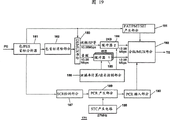
Figure 19 is the block scheme of expression PS/TS transducer 171 shown in Figure 180 (converting means) exemplary architecture.The inner structure of PS/TS transducer 171 shown in Figure 19 also can be applied to above-mentioned first and second embodiment respectively, i.e. PS/ TS transducer 74 and 98 shown in Fig. 5 and 14.
The bag data of the MPEG-PS form that has been carried out VBR control or maximum rate control are provided to bag/PES head analyzer 181.Bag/PES head analyzer 181 is caught these bag data and it is stored in the storer (not shown), checks the content of bag/PES head.Bag/PES head analyzer 181 detects the stream ID of each bag head, so that distribute voice data, video data and sub-image data according to the stream ID that detects.
In addition, bag/PES head analyzer 181 also offers PAT (program correlation table)/PMT (Program Map Table)/SIT (service information list) to stream ID with other data and produces part 191.
SCR is detected by the bag head that the bag data that provide via bag/PES head analyzer 181 are provided in SCR (system clock reference) test section 187.
PCR (timer reference of programs) produces part 189 and utilizes the counter of 27MHz to produce TS PCR, and the counter bit of this 27MHz is in the STC of disk drive 71 1 sides (system time clock) produces circuit 188.The initialization of STC increases fixing delay by the SCR that gives output at first and finishes.Also STC because of piece ballistic kick (a rush of a block), for example tilted block (angle block) appear, blocking-up (block-out) waits and carries out initialization when occurring being offset.
The bag head is eliminated part 182 and is eliminated the bag head, to save the downstream buffer capacity of demultiplexer 183 (tripping device).183 of demultiplexers (DEMUX) are eliminated the bag data that part 182 provides the separating audio bag and are provided it to first impact damper 185 (impact damper 1) from the bag head.Demultiplexer 183 is all the other bags that video packets, sub-picture pack and direct packets offer second impact damper 184 (impact damper 2).
Audio stream is that first impact damper 185 of 4K byte temporarily receives by size, and the 4K byte is the length of PS audio buffer.Slip calculating/read-out control part divides the output rating of 186 calculating, first impact damper 185, so that make it be less than or equal to 2Mbps (slip of the transmission impact damper 151 of T_STD shown in Figure 17), according to rate calculated control reading to TS grouping parts (TS grouping/MUX part) 192 (multiplex machines).
As shown in figure 20, preceding 8 of TS bag head is sync byte (sync_byte), is set to " 010000111 ".Then one is error indicator (transport_error_indicator), is set to " 0 " or " 1 ".Then one is that the unit begins designator (payload_unit_start_indicator), is decided to be " 0 " or " 1 ".Then a bit representation packet priority (transport_priority) is set to " 0 " or " 1 ".
Then 13 is PID, according to bag type setting value as shown in figure 18.Then 2 bit representation scramblings controls (transport_scrambling_control) are set to " 00 ".Then 2 bit representations adapt to field control (adaptation_field_control), are set to " 00 " or " 11 ".Then 4 is continuity counter (continuity_counter), and is used for detecting the information that has abandoned the bag with identical PID whether halfway.
Under the situation of the MPEG2-TS that does not comprise any adaptation field (therefore not having PCR), TS bag head is made up of above-mentioned 4 bytes.On the contrary, under the situation that comprises the MPEG2-TS that adapts to field (therefore PCR is arranged), add the following information that is provided with again.Preceding 8 that adapt to field is to adapt to field length, is set to " 00000111 " (=7).Then 1 is uncontinuity designator (discontinuity_indicator), is set to " 0 " or " 1 ".
Then 1 is random access indicator (random_access_indicator), is set to " 0 ".Then 1 is flow priority designator (ES_priority_indicator), is set to " 0 ".
Then 1 is " PCR (timer reference of programs) _ flag ", is set to " 1 ".Then 1 is " OPCR (original program clock reference) _ flag ", is set to " 0 ".Then 1 " splicing_point_flag " is set to " 0 ".Then 1 is " transport_private_data_flag ", is set to " 0 ".
In following 48, set PCR.Specifically, preceding 33 is " program_clock_reference_flag ", and then 6 is " reserved ", i.e. reserve area, and last 9 is " PCR_extension ".
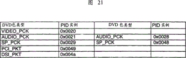
As shown in figure 21, video packets (VIDEO_PACK) represents that with PID " 0x0020 " (0x represents that " 0020 " is 16 system numbers) audio pack (AUDIO_PACK) is represented with PID " 0x0021 " to " 0x0028 ".Sub-picture pack (SP_PACK) is represented with PID " 0x0029 " to " 0x0048 "." PCI (program chain information) _ PKT " represents with PID " 0x0049 ", and " DSI (code translator standard information) _ PKT " represents with PID " 0x004a ".
Though user's specific regions of PID shown in Figure 21 is that " 0x0010 " is to " 0x1FFE ", but consider compatibility with STB (set top box), should avoid using the zone " 0x0010 " of being used to " 0x0016 ", " 0x0020 " to " 0x004a " is used for DVD by STB.
PAT/PMT/SIT produces part 191 according to generation various tables, for example PAT, PMT, SIT and DIT (uncontinuity information table) such as stream ID from each bag header detection.Voice data, the video data of second impact damper 184, sub-image data, the PAT/PMT/SIT of TS grouping parts 192 multiplexed first impact dampers 185 produce the table information of part 191 and the PCR of PCR insertion portion 190 etc., so that produce transport stream packet thus.
The operation of the 5th embodiment is below described.Because the other parts of DVD player 61 are operated according to the mode identical with above first embodiment that describes referring to Fig. 5 basically, so the operation of the relevant part of following description and maximum rate control section 72B and PS/TS transducer 171.Because indication equipment 63-1 to 63-3 operates according to the mode identical with the above mode of describing referring to Fig. 5, so the following operation of not describing them.
For example, when the user controls the appointment normal reproduction, just offer VBR control section 72A by switch 76 from coiling the 101 expression data of reproducing.Because the structure of VBR control section 72A and operate all identical with VBR control section 72 shown in Figure 5 is not so be described them at this.
On the contrary, when the user controls the appointment trickplay modes, when for example F.F., inverted order were reproduced or doubly speed is reproduced, the information of controlling corresponding to this user just offered boot manager 11 by user interface control section 24.So boot manager 11 just detects the input to trickplay modes, gauge tap 76 is also switched its inner connection, so that the reproduction data of dish 101 are sent to maximum rate control section 72B.
When the MPEG2 formatted data that output panel 101 provides by switch 76, maximum rate control section 72B checks, so that be no more than the transfer rate (maximum rate) that IEEE1394 predesignates.
In other words, if think and will surpass maximum rate, maximum rate control section 72B just by boot manager 11 to the optical picking-up head (not shown) provide indication its suspend from coiling 101 signals of reading.In response, optical picking-up head is read from coiling 101 data with regard to stopping.May be resumed by state in case transmit, maximum rate control section 72B just provides to optical picking-up head by boot manager 11 and indicates it to restart from coiling the signal of 101 sense datas.In response, optical picking-up head restarts to coil 101 data and reads.Maximum rate control section 72B has so just controlled speed, prevents that transmission line from breaking down.
The data of having been carried out rate controlled by VBR control section 72A or maximum rate control section 72B are transmitted to sub-DEMUX part 73, and unnecessary wrapping in this sub-DEMUX part 73 is eliminated.The data that obtain are transmitted to PS/TS transducer 171.
The data that so send PS/TS transducer 171 to are transfused to bag/PES head analyzer 181.These data are the bag data that have been carried out the MPEG-PS form of VBR control or maximum rate control.Bag/PES head analyzer 181 is caught these data and it is stored in the storer (not shown), checks the content of bag/PES head.Bag/PES head analyzer 181 detects the stream ID of each bag head, so that distribute voice data, video data and sub-image data according to the stream ID that detects.
In addition, stream ID and other data also send PAT/PMT/SIT to and produce part 191.
Also provide the bag data by bag/PES head analyzer 181 to SCR test section 187, SCR is detected by the bag head of analyzing these bag data in this SCR test section 187.Detected SCR offers PCR and produces part 189.
PCR produces part 189 and utilizes the counter of 27MHz to produce TS PCR, and the counter bit of this 27MHz produces in the circuit 188 in the STC of disk drive 71 1 sides.The initialization of STC increases fixing delay by the SCR that gives output at first and finishes.Also skew occurs and the time carry out initialization because of piece ballistic kick, for example tilted block, blocking-up etc. occurring at STC.
The bag head of the bag data that bag head elimination part 182 elimination bag/PES head analyzers 181 provide is to save the downstream buffer capacity of demultiplexer 183.Remainder data offers demultiplexer (DEMUX) 183.183 of demultiplexers are eliminated the bag data that part 182 provides the separating audio bag and are provided it to first impact damper 185 (impact damper 1) from the bag head.All the other bags are that video packets, sub-picture pack and direct packets offer second impact damper 184 (impact damper 2).
Audio stream is that first impact damper 185 of 4K byte temporarily receives by size, and the 4K byte is the length of PS audio buffer.Slip calculating/read-out control part divides the output rating of 186 calculating, first impact damper 185, so that make it be less than or equal to 2Mbps, and according to rate calculated control reading TS grouping parts (TS grouping/MUX part) 192.
Output regularly controlled voice data will be transformed to the TS bag and carry out multiplexed with other stream (video data etc.) again.If this is multiplexed to postpone other stream, just may cause the video buffer underflow of code translator one side.Consider this point, according to the audio leakage rate speed after multiplexed is decided to be 12.08 (=10.08+2.0) Mbps.
Therefore, TS grouping parts 192 are also by second impact damper, 185 receiving video datas and other stream (for example sub-image data), and according to audio pack multiplexed these data of such timing that do not occur conflicting.At this moment, owing to make output rating increase the audio leakage rate as mentioned above, so the transmission of video data and other data is not postponed.
Final transfer rate after the TS conversion increases the value of wrapping the redundance of the such table information sum of head and for example PAT, PMT and SIT corresponding to TS.
Because the above-mentioned processing of voice data all is necessary to each audio stream, so at most, promptly when all audio streams of output, need the impact damper of 32K byte (=4K byte * 8).
Like this, the mpeg data of program stream type just is transformed to the mpeg data of transport stream type and by its output in PS/TS transducer 171.At this moment, voice data and other data, for example video data and sub-image data are temporarily stored in the corresponding buffers (impact damper 1 and impact damper 2), and once more by multiplexed, so that do not cause the audio buffer overflow of code translator one side.Therefore, even when the input rate is 10.08Mbps, can have yet and interruptedly reproduce sound.
The invention is not restricted to the foregoing description, can be applied to miscellaneous equipment and system.
In addition, the concrete numerical value that occurs in the foregoing description is exemplary, the invention is not restricted to these numerical value.
As mentioned above, in data encoding system of the present invention and data decoding method, first equipment is the data conversion of first form data of second form, send the data of this second form then, perhaps second equipment receives the data of first form and it is transformed to the data of second form, and second equipment is deciphered the data of this second form.Therefore, utilize equipment just can reproduce the data that are recorded on the DVD with the code translator that is suitable for handling transport stream.
In data encoding system of the present invention, first equipment reproduces the data that are recorded on the given recording medium and passes through the IEEE1394 interface and transmit reproduced data, a plurality of second equipment receive the data transmitted and the data that received are carried out digital-analog conversion by the IEEE1394 interface, with the output simulating signal.Therefore, the data that are recorded on the DVD can be reproduced.
In transfer equipment of the present invention and transfer approach, the data of first form are transformed to the data of second form that is the data mode in the code translator, and the data of this second form are transmitted.Therefore, utilize equipment just can reproduce the data that are recorded on the DVD with the code translator that is suitable for handling transport stream.
In receiving equipment of the present invention and method of reseptance, the data of first form are received, and the data of this first form are transformed to the data of second form that is the data mode in the code translator, and the data of this second form are decoded.Therefore, the data that are recorded on the DVD can be reproduced.
In receiving equipment of the present invention and method of reseptance, the data of first form or second form are received and are provided for the first decoding part or the second decoding part according to the form that receives data.First code translator is deciphered the data of first form, or second code translator is deciphered the data of second form.Therefore, the data that are recorded on the DVD can be reproduced.
Claims (60)
1. data encoding system comprises:
First equipment transmits coded data by digital interface; And
Second equipment receives data that transmit through digital interface and the data that receive for given data layout decoding, wherein:
Described first equipment or described second equipment comprise the converting means that the first form data is transformed to the second form data;
Described second equipment comprises code translator, and this device is used to decipher the described second form data.
2. data encoding system as claimed in claim 1, wherein said first form are the program streams of MPEG (Motion Picture Experts Group) scheme, and described second form is the transport stream of MPEG scheme.
3. data encoding system as claimed in claim 1, wherein said converting means comprise the impact damper of the temporary described first form data.
4. data encoding system as claimed in claim 3, wherein said converting means also comprises the tripping device that the first form data is separated into the data of voice data and non-audio data, and wherein said impact damper is made up of with an impact damper of the data of temporary described non-audio data an impact damper of temporary described voice data.
5. data encoding system as claimed in claim 4, wherein said converting means comprise the impact damper of described voice data of the same number of number of temporary and audio data stream.
6. data encoding system as claimed in claim 5, the capacity that each described impact damper of wherein temporary voice data has the 4K byte.
7. data encoding system as claimed in claim 2, wherein said converting means comprise that also the data of multiplexed audio data and non-audio data produce the multiplex machine of MPEG transport stream.
8. the data decoding method in the data encoding system, described data encoding system has by digital interface and transmits first equipment of coded data and receive the data that transmit through described digital interface and decipher second equipment of the data of described reception, in described data decoding method:
Described first equipment is transformed to the second form data to the first form data, sends the described second form data then, and perhaps described second equipment receives the described first form data and it is transformed to the second form data; And
Described second equipment is deciphered the described second form data.
9. data decoding method as claimed in claim 8, wherein said first form are the program streams of MPEG scheme, and described second form is the transport stream of MPEG scheme.
10. data decoding method as claimed in claim 8, wherein said first or second equipment is the temporary described first form data when the described first form data of conversion.
11. data decoding method as claimed in claim 10, wherein, when the described first form data of conversion, described first or second equipment is separated into the data of voice data and non-audio data to the described first form data, the data of temporary respectively then described voice data and described non-audio data.
12. data decoding method as claimed in claim 11, wherein, when the described first form data of conversion, the voice data of the number that described first or second device storage is identical with flow amount.
13. data decoding method as claimed in claim 9, wherein, when the described first form data of conversion, the data of the described first or second multiplexed described voice data of equipment and described non-audio data produce the MPEG transport stream.
14. a data encoding system comprises:
First equipment reproduces the data that are recorded on the given recording medium, and transmits described reproduction data by IEEE (Institute of Electrical and Electric Engineers) 1394 interfaces; And
A plurality of second equipment receive the data that transmit through the IEEE1394 interface, and described reception data are carried out digital-analog conversion, with the output simulating signal.
15. a transfer equipment sends coded data to a code translator by digital interface, described code translator is deciphered described coded data for given data mode, and described transfer equipment comprises:
Converting means, it is the second form data of the given data mode in the code translator that the first form data are transformed to; And
Conveyer transmits the described second form data.
16. transfer equipment as claimed in claim 15, wherein said first form are the program streams of MPEG scheme, described second form is the transport stream of MPEG scheme.
17. transfer equipment as claimed in claim 15, wherein said converting means comprise the impact damper of the temporary described first form data.
18. transfer equipment as claimed in claim 17, wherein said converting means also comprises the tripping device that the described first form data is separated into the data of voice data and non-audio data, and wherein said impact damper is made up of with an impact damper of the data of temporary described non-audio data an impact damper of temporary described voice data.
19. transfer equipment as claimed in claim 18, wherein said converting means comprise the impact damper with the temporary described voice data of the same number of number of audio data stream.
20. transfer equipment as claimed in claim 19, the capacity that each described impact damper of wherein temporary voice data has the 4K byte.
21. transfer equipment as claimed in claim 16, wherein said converting means comprise that also the data of multiplexed described voice data and described non-audio data produce the multiplex machine of MPEG transport stream.
22. transfer equipment as claimed in claim 15, wherein said digital interface is constructed according to the IEEE1394 form.
23. transfer equipment as claimed in claim 15, the wherein said first form data are data of reproducing from digital universal disc.
24. a transfer approach sends coded data to a code translator by digital interface, described code translator is deciphered described coded data for given data mode, and described transfer approach may further comprise the steps:
It is the second form data of the given data mode in the code translator that the first form data are transformed to; And
Transmit the described second form data.
25. transfer approach as claimed in claim 24, wherein said first form are the program streams of MPEG scheme, described second form is the transport stream of MPEG scheme.
26. transfer approach as claimed in claim 24, wherein said shift step comprise the temporary described first form data.
27. transfer approach as claimed in claim 26, wherein said shift step comprise the data that the described first form data are separated into voice data and non-audio data, and the data of temporary respectively described voice data and described non-audio data.
28. transfer approach as claimed in claim 27, wherein said shift step comprise the voice data of the number that storage is identical with flow amount.
29. transfer approach as claimed in claim 25, wherein said shift step comprise that the data of multiplexed described voice data and described non-audio data produce the MPEG transport stream.
30. transfer approach as claimed in claim 24, wherein said digital interface is constructed according to the IEEE1394 form.
31. transfer approach as claimed in claim 24, the wherein said first form data are data of reproducing from digital universal disc.
32. the receiving equipment in the data encoding system receives the coded data that transmits through digital interface and deciphers described reception data for given data mode, described receiving equipment comprises:
Receiving trap receives the first form data;
Converting means, it is the second form data of described given data mode that the described first form data are transformed to; And
Code translator is deciphered the described second form data.
33. receiving equipment as claimed in claim 32, wherein said first form are the program streams of MPEG scheme, described second form is the transport stream of MPEG scheme.
34. receiving equipment as claimed in claim 32, wherein said digital interface is constructed according to the IEEE1394 form.
35. receiving equipment as claimed in claim 32, wherein said converting means comprise the impact damper of the temporary first form data.
36. receiving equipment as claimed in claim 35, wherein said converting means also comprises the tripping device that the first form data is separated into the data of voice data and non-audio data, and wherein said impact damper is made up of with an impact damper of the data of temporary described non-audio data an impact damper of temporary described voice data.
37. receiving equipment as claimed in claim 36, wherein said converting means comprise the impact damper of described voice data of the same number of number of temporary and audio data stream.
38. receiving equipment as claimed in claim 37, the capacity that each described impact damper of wherein temporary voice data has the 4K byte.
39. receiving equipment as claimed in claim 33, wherein said converting means comprise that also the data of multiplexed described voice data and described non-audio data produce the multiplex machine of MPEG transport stream.
40. the method for reseptance in the data encoding system receives the coded data that transmits through digital interface and deciphers described reception data for given data mode, described method of reseptance may further comprise the steps:
Receive the first form data;
It is the second form data of described given data mode that the described first form data are transformed to; And
Decipher the described second form data.
41. method of reseptance as claimed in claim 40, wherein said first form are the program streams of MPEG scheme, described second form is the transport stream of MPEG scheme.
42. method of reseptance as claimed in claim 40, wherein said shift step comprise the temporary described first form data.
43. method of reseptance as claimed in claim 42, wherein said shift step comprise the data that the described first form data are separated into voice data and non-audio data, and the data of temporary respectively described voice data and described non-audio data.
44. method of reseptance as claimed in claim 43, wherein said shift step comprise the voice data of the number that storage is identical with flow amount.
45. method of reseptance as claimed in claim 41, wherein said shift step comprise that the data of multiplexed described voice data and described non-audio data produce the MPEG transport stream.
46. method of reseptance as claimed in claim 40, wherein said digital interface is constructed according to the IEEE1394 form.
47. method of reseptance as claimed in claim 40, the wherein said first form data are data of reproducing from digital universal disc.
48. the receiving equipment in the data encoding system receives the coded data that transmits through digital interface and deciphers described reception data for given data mode, described receiving equipment comprises:
First code translator is deciphered the first form data;
Second code translator is deciphered the second form data; And
Feedway receives the described first or second form data, according to the form of described reception data described reception data is offered described first code translator or described second code translator.
49. receiving equipment as claimed in claim 48, wherein said first form are the program streams of MPEG scheme, described second form is the transport stream of MPEG scheme.
50. the method for reseptance in the data encoding system receives the coded data that transmits through digital interface and deciphers described reception data for given data mode, described method of reseptance may further comprise the steps:
Receive the data of first form or second form, and described reception data are offered the first decoding part or the second decoding part according to the form of described reception data;
The described first form data of decoding in the first decoding part; And
The described second form data of decoding in the second decoding part.
51. a recording medium replay equipment sends the coded data of reading from a recording medium to a code translator by digital interface, described code translator is deciphered described coded data for given data mode, and described recording medium replay equipment comprises:
The variable bit rate control section receives one from described recording medium and reproduces signal, and according to given timing it exported;
The maximum rate control section receives one from described recording medium and reproduces signal, checks the output rating of described maximum rate control section, so that described output rating is no more than the transfer rate of described digital interface;
Switch offers variable bit rate control section or maximum rate control section reproducing data selectively according to the playback mode of described recording medium;
Converting means, it is the second form data of the given data mode in the code translator that the first form data that provided by described variable bit rate control section or described maximum rate control section are transformed to; And
Conveyer transmits the described second form data.
52. recording medium replay equipment as claimed in claim 51, the such Be Controlled of wherein said switch, promptly when the pattern of selected normal playback recording medium, described reproduction data are offered described variable bit rate control section, and when selecting trickplay modes, described reproduction data are offered described maximum rate control section.
53. recording medium replay equipment as claimed in claim 51, wherein said first form are the program streams of MPEG scheme, described second form is the transport stream of MPEG scheme.
54. recording medium replay equipment as claimed in claim 51, wherein said converting means comprise the impact damper of the temporary described first form data.
55. recording medium replay equipment as claimed in claim 54, wherein said converting means also comprises the tripping device that the first form data is separated into the data of voice data and non-audio data, and wherein said impact damper is made up of with an impact damper of the data of temporary described non-audio data an impact damper of temporary described voice data.
56. recording medium replay equipment as claimed in claim 55, wherein said converting means comprise the impact damper of keeping in this voice data with the same number of number of audio data stream.
57. recording medium replay equipment as claimed in claim 56, the capacity that each described impact damper of wherein temporary voice data has the 4K byte.
58. recording medium replay equipment as claimed in claim 53, wherein said converting means comprise that also the data of multiplexed described voice data and described non-audio data produce the multiplex machine of MPEG transport stream.
59. recording medium replay equipment as claimed in claim 51, wherein said digital interface is constructed according to the IEEE1394 form.
60. recording medium replay equipment as claimed in claim 51, the wherein said described first form data are data of reproducing from digital universal disc.
Applications Claiming Priority (6)
| Application Number | Priority Date | Filing Date | Title |
|---|---|---|---|
| JP256837/96 | 1996-09-27 | ||
| JP256837/1996 | 1996-09-27 | ||
| JP25683796 | 1996-09-27 | ||
| JP14142597A JPH10154373A (en) | 1996-09-27 | 1997-05-30 | Data decoding system and method thereof, transmission unit and method thereof and receiver device and method thereof |
| JP141425/1997 | 1997-05-30 | ||
| JP141425/97 | 1997-05-30 |
Publications (2)
| Publication Number | Publication Date |
|---|---|
| CN1188963A CN1188963A (en) | 1998-07-29 |
| CN1122273C true CN1122273C (en) | 2003-09-24 |
Family
ID=26473663
Family Applications (1)
| Application Number | Title | Priority Date | Filing Date |
|---|---|---|---|
| CN97126017A Expired - Fee Related CN1122273C (en) | 1996-09-27 | 1997-09-27 | Data decoding system and method, transfer device and method, and receiving device and method |
Country Status (5)
| Country | Link |
|---|---|
| US (1) | US6211800B1 (en) |
| EP (1) | EP0833514A3 (en) |
| JP (1) | JPH10154373A (en) |
| KR (1) | KR19980024869A (en) |
| CN (1) | CN1122273C (en) |
Families Citing this family (118)
| Publication number | Priority date | Publication date | Assignee | Title |
|---|---|---|---|---|
| US5619501A (en) * | 1994-04-22 | 1997-04-08 | Thomson Consumer Electronics, Inc. | Conditional access filter as for a packet video signal inverse transport system |
| CA2216573C (en) * | 1996-10-01 | 2006-03-14 | Sony Corporation | Digital tuner having ieee 1394 serial bus interface for providing a plurality of selected programs as a functional unit |
| JP3656874B2 (en) | 1997-07-04 | 2005-06-08 | ソニー株式会社 | Electronic device control system and method, playback device, and output device |
| US6618396B1 (en) * | 1997-07-29 | 2003-09-09 | Matsushita Electric Ind Co Ltd | Data transmitting device, data receiving device, and data recording device |
| EP2146499B1 (en) * | 1997-11-14 | 2012-10-31 | Sony Deutschland Gmbh | Distribution of MPEG-2 transport streams on the IEEE 1394-based home network |
| US7068920B1 (en) * | 1998-02-04 | 2006-06-27 | Thomson Licensing | Digital baseband interface for a DVD player |
| ES2332076T3 (en) * | 1998-02-04 | 2010-01-25 | Thomson Consumer Electronics, Inc. | BASE BAND INTERFACE FOR DVD PLAYER. |
| KR100329496B1 (en) * | 1998-03-17 | 2002-03-23 | 마츠시타 덴끼 산교 가부시키가이샤 | Data transmission apparatus and method thereof using command adapted thereto |
| US20030133448A1 (en) * | 1998-04-03 | 2003-07-17 | Craig R. Frink | Packet protocol for encoding and decoding video data and data flow signals and devices for implementing the packet protocol |
| JP3844877B2 (en) * | 1998-04-08 | 2006-11-15 | パイオニア株式会社 | Stream converter |
| US20020056081A1 (en) * | 1999-12-02 | 2002-05-09 | Qualcomm Incorporated | Apparatus and method for decoding digital image and audio signals |
| EP0957487B1 (en) * | 1998-05-13 | 2010-06-30 | Panasonic Corporation | Data transmission apparatus and method therefor |
| US6785289B1 (en) * | 1998-06-05 | 2004-08-31 | Sarnoff Corporation | Method and apparatus for aligning sub-stream splice points in an information stream |
| DE19927711B4 (en) * | 1998-06-19 | 2004-09-23 | Samsung Electronics Co., Ltd., Suwon | Device for transmitting information over a network |
| KR100304644B1 (en) * | 1998-06-19 | 2001-11-02 | 윤종용 | Apparatus and method for transmitting informtion via network |
| GB2351888B (en) * | 1998-06-19 | 2002-03-06 | Samsung Electronics Co Ltd | Apparatus for transmitting information via network and method thereof |
| DE19964394B4 (en) * | 1998-06-19 | 2004-09-16 | Samsung Electronics Co., Ltd., Suwon | Transmission device for transferring digital video disc information over a network |
| US6564255B1 (en) * | 1998-07-10 | 2003-05-13 | Oak Technology, Inc. | Method and apparatus for enabling internet access with DVD bitstream content |
| US6505255B1 (en) | 1999-04-29 | 2003-01-07 | Mitsubishi Electric Information Technology Center America, Inc. (Ita) | Method for formatting and routing data between an external network and an internal network |
| US6496862B1 (en) | 1998-08-25 | 2002-12-17 | Mitsubishi Electric Research Laboratories, Inc. | Remote monitoring and control of devices connected to an IEEE 1394 bus via a gateway device |
| US7013354B1 (en) * | 1998-10-05 | 2006-03-14 | Canon Kabushiki Kaisha | Channel protocol for IEEE 1394 data transmission |
| KR100606518B1 (en) * | 1998-10-14 | 2007-07-10 | 엘지전자 주식회사 | An apparatus and a method for transformatting a data stream format |
| JP3602728B2 (en) | 1998-10-22 | 2004-12-15 | 株式会社東芝 | Digital video disk player and image display device |
| US6363207B1 (en) * | 1998-10-22 | 2002-03-26 | Sony Corporation | Method and apparatus for a virtual system time clock for digital audio/video processor |
| JP3551045B2 (en) * | 1998-11-02 | 2004-08-04 | 松下電器産業株式会社 | Data transmitting / receiving apparatus and method |
| JP4010066B2 (en) * | 1998-11-09 | 2007-11-21 | ソニー株式会社 | Image data recording apparatus and recording method, and image data recording / reproducing apparatus and recording / reproducing method |
| JP2000173181A (en) | 1998-12-04 | 2000-06-23 | Sony Corp | Data recording device and outputting device, data output system, methods for data recording and outputting, and data recording and outputting method |
| WO2000041056A2 (en) * | 1999-01-06 | 2000-07-13 | Digital Video Express, L.P. | Digital content distribution system and method |
| WO2000046803A1 (en) * | 1999-02-05 | 2000-08-10 | Kabushiki Kaisha Toshiba | Method for creating stream data and method for partial deletion |
| KR100540645B1 (en) * | 1999-03-03 | 2006-01-10 | 삼성전자주식회사 | Apparatus for transferring DVD information and method thereof |
| JP3529665B2 (en) * | 1999-04-16 | 2004-05-24 | パイオニア株式会社 | Information conversion method, information conversion device, and information reproduction device |
| US6523064B1 (en) | 1999-04-29 | 2003-02-18 | Mitsubishi Electric Research Laboratories, Inc | Network gateway for collecting geographic data information |
| US6378000B1 (en) | 1999-04-29 | 2002-04-23 | Mitsubish Electric Research Laboratories, Inc | Address mapping in home entertainment network |
| US6633547B1 (en) | 1999-04-29 | 2003-10-14 | Mitsubishi Electric Research Laboratories, Inc. | Command and control transfer |
| KR100360285B1 (en) * | 1999-05-20 | 2002-11-04 | 엘지전자 주식회사 | A METHOD AND APPARATUS FOR TRANSCEIVING AUDIO Data STREAM Through DIGITAL INTERFACE |
| BR0006156A (en) * | 1999-05-25 | 2001-10-30 | Sony Corp | Transmission process, apparatus and system |
| TW501354B (en) * | 1999-05-25 | 2002-09-01 | Sony Corp | Digital signal processing device and method, digital signal processing system |
| JP4313894B2 (en) * | 1999-06-01 | 2009-08-12 | キヤノン株式会社 | Communication system and controlled device |
| JP2001028748A (en) * | 1999-07-12 | 2001-01-30 | Sony Corp | Data reproduction transmitter and data reproduction transmission method |
| KR100643437B1 (en) * | 1999-07-30 | 2006-11-13 | 엘지전자 주식회사 | Method and apparatus for transmitting digital video and audio stream through digital interface |
| US7020384B1 (en) * | 1999-08-12 | 2006-03-28 | Lg Electronics Inc. | Method for creating and recording transport time information for data recorded on a disk |
| KR100376578B1 (en) | 1999-08-12 | 2003-03-17 | 엘지전자 주식회사 | Method for recoding digital data stream and providing presentation control information therefor |
| KR100635014B1 (en) * | 1999-08-25 | 2006-10-16 | 삼성전자주식회사 | Digital broadcasting receiver processing a number of input stream |
| JP2001156807A (en) * | 1999-09-14 | 2001-06-08 | Sony Corp | Method, system, and device for transmission |
| JP2001086139A (en) * | 1999-09-14 | 2001-03-30 | Sony Corp | Transmission method and its device |
| GB9930788D0 (en) * | 1999-12-30 | 2000-02-16 | Koninkl Philips Electronics Nv | Method and apparatus for converting data streams |
| GB9930787D0 (en) * | 1999-12-30 | 2000-02-16 | Koninkl Philips Electronics Nv | Method and apparatus for convrerting data streams |
| US6938256B2 (en) | 2000-01-18 | 2005-08-30 | Galactic Computing Corporation | System for balance distribution of requests across multiple servers using dynamic metrics |
| JP3957251B2 (en) * | 2000-03-02 | 2007-08-15 | パイオニア株式会社 | Audio information reproducing system, audio information reproducing apparatus, and audio information reproducing method |
| US6801536B1 (en) * | 2000-03-23 | 2004-10-05 | International Business Machines Corporation | Remultiplexing audio/video PES streams from an MPEG transport system |
| GB0007870D0 (en) | 2000-03-31 | 2000-05-17 | Koninkl Philips Electronics Nv | Methods and apparatus for making and replauing digital video recordings, and recordings made by such methods |
| JP3896768B2 (en) * | 2000-05-31 | 2007-03-22 | 日本電気株式会社 | MPEG video elementary stream extraction apparatus and elementary stream extraction method used therefor |
| US7366402B2 (en) * | 2000-06-02 | 2008-04-29 | Lg Electronics Inc. | Method and apparatus of recording a high definition digital television broadcast signal |
| US8091106B1 (en) * | 2000-06-26 | 2012-01-03 | Thomson Licensing | Method and apparatus for using DVD subpicture information in a television receiver |
| US8538843B2 (en) | 2000-07-17 | 2013-09-17 | Galactic Computing Corporation Bvi/Bc | Method and system for operating an E-commerce service provider |
| CN1285055C (en) * | 2000-07-17 | 2006-11-15 | 蚬壳星盈科技有限公司 | Method and system for providing dynamic hosted sevvice management |
| US6816905B1 (en) | 2000-11-10 | 2004-11-09 | Galactic Computing Corporation Bvi/Bc | Method and system for providing dynamic hosted service management across disparate accounts/sites |
| JP2002051307A (en) * | 2000-08-02 | 2002-02-15 | Sony Corp | Device and method for processing image and recording medium |
| US6741292B1 (en) | 2000-11-06 | 2004-05-25 | Koninklijke Philips Electronics N.V. | System and method for a baseband digital television |
| JP3780853B2 (en) | 2001-02-28 | 2006-05-31 | ヤマハ株式会社 | Audio data recording medium playback device |
| JP3633884B2 (en) * | 2001-06-01 | 2005-03-30 | 松下電器産業株式会社 | Playback image transmission device |
| KR100470025B1 (en) | 2001-06-15 | 2005-02-04 | 엘지전자 주식회사 | Apparatus and method for recording a digital data stream, and medium thereof |
| DE10136176A1 (en) * | 2001-07-25 | 2003-02-13 | Thomson Brandt Gmbh | Digital video device for integration in the network |
| US7486680B1 (en) | 2002-03-21 | 2009-02-03 | Ji Zhang | Packet schedule timestamp for a compressed bitstream |
| US8284844B2 (en) | 2002-04-01 | 2012-10-09 | Broadcom Corporation | Video decoding system supporting multiple standards |
| US7693399B2 (en) * | 2002-07-11 | 2010-04-06 | Lg Electronics Inc. | Method for providing program specific information recorded on high density disc medium |
| KR20040009927A (en) * | 2002-07-26 | 2004-01-31 | 삼성전자주식회사 | Information storage medium for storing information of generating DTV stream, method for transcoding the information thereon as DTV stream and apparatus therefor |
| EP1535136A4 (en) | 2002-09-05 | 2009-06-17 | Lg Electronics Inc | Recording medium having data structure for managing reproduction of slideshows recorded thereon and recording and reproducing methods and apparatuses |
| JP4520853B2 (en) | 2002-09-06 | 2010-08-11 | エルジー エレクトロニクス インコーポレイティド | RECORDING MEDIUM HAVING DATA STRUCTURE FOR MANAGING PLAYING STOP VIDEO, RECORDING AND REPRODUCING METHOD AND DEVICE USING THE SAME |
| KR100811167B1 (en) * | 2002-11-04 | 2008-03-07 | 삼성전자주식회사 | Method of selecting audio language for Set-Top Box |
| US7639921B2 (en) | 2002-11-20 | 2009-12-29 | Lg Electronics Inc. | Recording medium having data structure for managing reproduction of still images recorded thereon and recording and reproducing methods and apparatuses |
| TWI271721B (en) | 2003-01-20 | 2007-01-21 | Lg Electronics Inc | Recording medium having data structure for managing reproduction of still pictures recorded thereon and recording and reproducing methods and apparatuses |
| US8055117B2 (en) | 2003-02-15 | 2011-11-08 | Lg Electronics Inc. | Recording medium having data structure for managing reproduction duration of still pictures recorded thereon and recording and reproducing methods and apparatuses |
| US8041179B2 (en) | 2003-02-24 | 2011-10-18 | Lg Electronics Inc. | Methods and apparatuses for reproducing and recording still picture and audio data and recording medium having data structure for managing reproduction of still picture and audio data |
| EP1890489B1 (en) | 2003-04-10 | 2010-05-12 | Panasonic Corporation | Information recording medium, and apparatus and method for recording information to information recording medium |
| JP4346966B2 (en) * | 2003-06-13 | 2009-10-21 | キヤノン株式会社 | Imaging device |
| US7555009B2 (en) | 2003-11-14 | 2009-06-30 | Canon Kabushiki Kaisha | Data processing method and apparatus, and data distribution method and information processing apparatus |
| EP1562382B1 (en) * | 2004-01-26 | 2019-09-04 | Socionext Inc. | Format conversion device and format conversion method |
| WO2005108247A2 (en) * | 2004-05-10 | 2005-11-17 | Innova Patent Gmbh | Conveying apparatus comprising a belt conveyor |
| CA2562427C (en) * | 2005-10-05 | 2012-07-10 | Lg Electronics Inc. | A digital broadcast system and method of processing traffic information |
| CA2562194C (en) | 2005-10-05 | 2012-02-21 | Lg Electronics Inc. | Method of processing traffic information and digital broadcast system |
| WO2007091779A1 (en) | 2006-02-10 | 2007-08-16 | Lg Electronics Inc. | Digital broadcasting receiver and method of processing data |
| WO2007126196A1 (en) | 2006-04-29 | 2007-11-08 | Lg Electronics Inc. | Digital broadcasting system and method of processing data |
| WO2007136166A1 (en) * | 2006-05-23 | 2007-11-29 | Lg Electronics Inc. | Digital broadcasting system and method of processing data |
| US20080037956A1 (en) * | 2006-06-30 | 2008-02-14 | Scientific-Atlanta, Inc. | Systems and Methods of Generating Encapsulated MPEG Program Streams |
| US7873104B2 (en) * | 2006-10-12 | 2011-01-18 | Lg Electronics Inc. | Digital television transmitting system and receiving system and method of processing broadcasting data |
| KR101285887B1 (en) | 2007-03-26 | 2013-07-11 | 엘지전자 주식회사 | Digital broadcasting system and method of processing data in digital broadcasting system |
| KR101253185B1 (en) | 2007-03-26 | 2013-04-10 | 엘지전자 주식회사 | Digital broadcasting system and data processing method |
| KR101285888B1 (en) | 2007-03-30 | 2013-07-11 | 엘지전자 주식회사 | Digital broadcasting system and method of processing data in digital broadcasting system |
| KR20090004659A (en) * | 2007-07-02 | 2009-01-12 | 엘지전자 주식회사 | Digital broadcasting system and method of processing data in digital broadcasting system |
| KR20090004660A (en) * | 2007-07-02 | 2009-01-12 | 엘지전자 주식회사 | Digital broadcasting system and method of processing data in digital broadcasting system |
| KR101513028B1 (en) | 2007-07-02 | 2015-04-17 | 엘지전자 주식회사 | broadcasting receiver and method of processing broadcast signal |
| KR101405971B1 (en) * | 2007-07-02 | 2014-06-12 | 엘지전자 주식회사 | broadcasting receiver and method of processing broadcast signal |
| KR101531910B1 (en) * | 2007-07-02 | 2015-06-29 | 엘지전자 주식회사 | broadcasting receiver and method of processing broadcast signal |
| CA2692484C (en) | 2007-07-02 | 2013-04-16 | Lg Electronics Inc. | Digital broadcasting system and data processing method |
| KR20090004658A (en) * | 2007-07-02 | 2009-01-12 | 엘지전자 주식회사 | Digital broadcasting system and method of processing data in digital broadcasting system |
| KR101490246B1 (en) | 2007-07-02 | 2015-02-05 | 엘지전자 주식회사 | broadcasting receiver and method of processing broadcast signal |
| KR101405972B1 (en) | 2007-07-02 | 2014-06-12 | 엘지전자 주식회사 | broadcasting receiver and method of processing broadcast signal |
| KR20090002855A (en) * | 2007-07-04 | 2009-01-09 | 엘지전자 주식회사 | Digital broadcast system and method of processing signal |
| KR20090004661A (en) * | 2007-07-04 | 2009-01-12 | 엘지전자 주식회사 | Digital broadcasting system and method of processing data in digital broadcasting system |
| WO2009005326A2 (en) | 2007-07-04 | 2009-01-08 | Lg Electronics Inc. | Digital broadcasting system and method of processing data |
| US8433973B2 (en) * | 2007-07-04 | 2013-04-30 | Lg Electronics Inc. | Digital broadcasting system and method of processing data |
| KR20090004773A (en) | 2007-07-06 | 2009-01-12 | 엘지전자 주식회사 | Digital broadcasting system and method of processing data in digital broadcasting system |
| KR20090004722A (en) * | 2007-07-06 | 2009-01-12 | 엘지전자 주식회사 | Broadcast receiver and method of processing data |
| KR20090004061A (en) * | 2007-07-06 | 2009-01-12 | 엘지전자 주식회사 | Telematics terminal capable of receiving broadcast and method of processing broadcast signal |
| KR20090004725A (en) * | 2007-07-06 | 2009-01-12 | 엘지전자 주식회사 | Broadcast receiver and method of processing data of broadcast receiver |
| KR20090004059A (en) * | 2007-07-06 | 2009-01-12 | 엘지전자 주식회사 | Telematics terminal capable of receiving broadcast and method of processing broadcast signal |
| KR20090012180A (en) | 2007-07-28 | 2009-02-02 | 엘지전자 주식회사 | Digital broadcasting system and method of processing data in digital broadcasting system |
| MX2010002146A (en) | 2007-08-24 | 2010-04-07 | Lg Electronics Inc | Digital broadcasting system and method of processing data in digital broadcasting system. |
| WO2009038442A2 (en) * | 2007-09-21 | 2009-03-26 | Lg Electronics Inc. | Digital broadcasting receiver and method for controlling the same |
| WO2009038408A2 (en) * | 2007-09-21 | 2009-03-26 | Lg Electronics Inc. | Digital broadcasting system and data processing method |
| KR101572875B1 (en) | 2007-09-21 | 2015-11-30 | 엘지전자 주식회사 | Digital broadcasting system and method of processing data in digital broadcasting system |
| US7813310B2 (en) * | 2007-09-21 | 2010-10-12 | Lg Electronics, Inc. | Digital broadcasting receiver and method for controlling the same |
| JP4737200B2 (en) * | 2008-01-04 | 2011-07-27 | ソニー株式会社 | Data transmission method and electronic device |
| KR101648448B1 (en) * | 2008-04-29 | 2016-08-16 | 엘지전자 주식회사 | Transmitting/receiving system and method of processing data in the transmitting/receiving system |
| CN101605252B (en) * | 2009-07-17 | 2011-07-20 | 深圳创维数字技术股份有限公司 | Method and system for converting program stream into transport stream |
| JP4737340B2 (en) * | 2010-07-20 | 2011-07-27 | ソニー株式会社 | Data transmission method and electronic device |
| CN102354515B (en) * | 2011-08-31 | 2017-02-01 | 深圳市阿龙电子有限公司 | Vehicle-mounted DVD (Digital Video Disk) control method |
Family Cites Families (14)
| Publication number | Priority date | Publication date | Assignee | Title |
|---|---|---|---|---|
| US5291486A (en) * | 1991-08-19 | 1994-03-01 | Sony Corporation | Data multiplexing apparatus and multiplexed data demultiplexing apparatus |
| US5566174A (en) * | 1994-04-08 | 1996-10-15 | Philips Electronics North America Corporation | MPEG information signal conversion system |
| US5579183A (en) * | 1994-04-08 | 1996-11-26 | U.S. Philips Corporation | Recording and reproducing an MPEG information signal on/from a record carrier |
| JP3129143B2 (en) * | 1994-05-31 | 2001-01-29 | 松下電器産業株式会社 | Data transfer method |
| JP3371174B2 (en) * | 1994-09-22 | 2003-01-27 | ソニー株式会社 | Packet receiver |
| US5504757A (en) * | 1994-09-27 | 1996-04-02 | International Business Machines Corporation | Method for selecting transmission speeds for transmitting data packets over a serial bus |
| JP3531762B2 (en) * | 1994-11-22 | 2004-05-31 | ソニー株式会社 | Transmitter and receiver |
| US5621898A (en) * | 1994-11-29 | 1997-04-15 | Compaq Computer Corporation | Arbiter organization for serial bus transfers |
| US5619337A (en) * | 1995-01-27 | 1997-04-08 | Matsushita Electric Corporation Of America | MPEG transport encoding/decoding system for recording transport streams |
| KR0166735B1 (en) * | 1995-03-06 | 1999-03-20 | 김광호 | Multimedia compound |
| US5675139A (en) * | 1995-05-18 | 1997-10-07 | Symbol Technologies, Inc. | Interface arrangement for use with consumer devices |
| US5933430A (en) * | 1995-08-12 | 1999-08-03 | Sony Corporation | Data communication method |
| CA2216573C (en) * | 1996-10-01 | 2006-03-14 | Sony Corporation | Digital tuner having ieee 1394 serial bus interface for providing a plurality of selected programs as a functional unit |
| US5953674A (en) * | 1997-02-12 | 1999-09-14 | Qualcomm Incorporated | Asynchronous serial communications on a portable communication device serial communication bus |
-
1997
- 1997-05-30 JP JP14142597A patent/JPH10154373A/en not_active Abandoned
- 1997-09-23 US US08/933,734 patent/US6211800B1/en not_active Expired - Fee Related
- 1997-09-23 KR KR1019970048225A patent/KR19980024869A/en not_active Application Discontinuation
- 1997-09-24 EP EP19970307484 patent/EP0833514A3/en not_active Withdrawn
- 1997-09-27 CN CN97126017A patent/CN1122273C/en not_active Expired - Fee Related
Also Published As
| Publication number | Publication date |
|---|---|
| EP0833514A2 (en) | 1998-04-01 |
| EP0833514A3 (en) | 2003-02-12 |
| JPH10154373A (en) | 1998-06-09 |
| CN1188963A (en) | 1998-07-29 |
| KR19980024869A (en) | 1998-07-06 |
| US6211800B1 (en) | 2001-04-03 |
Similar Documents
| Publication | Publication Date | Title |
|---|---|---|
| CN1122273C (en) | Data decoding system and method, transfer device and method, and receiving device and method | |
| CN1162006C (en) | Transmitting apparatus and method, receiving apparatus and method | |
| CN1208777C (en) | Method for implementing trickplay modes in data stream recorder | |
| CN1251493C (en) | Recording apparatus and method, reproducing apparatus and method, and its recording carrier | |
| CN1076506C (en) | Data producing device | |
| CN1194552C (en) | Method and device for decoding digital video stream in digital video system | |
| CN1152569C (en) | Multiplexed data producing, encoded data reproducing, and clock conversion apparatus and method | |
| CN1199475C (en) | Method and apparatus for converting data streams | |
| CN1175415C (en) | Digital multipurpose disc voice frequency disc of storage voice frequency data and reproducing device | |
| CN1171452C (en) | Apparatus and methods for multiplexing, recording and controlling display of image data, and recording medium therefor | |
| CN1159917C (en) | Method and device for producing a trick mode in digital video system | |
| CN1235400C (en) | Receiving storage device, transmisison device, broadcasting system, Reiceiving storage method, transmission method, broadcasting method, program, and medium | |
| CN1299502C (en) | Decoding device and decoding method | |
| CN1252204A (en) | Optical disc and computer-readable storage medium, and recording method and apparatus therefor | |
| CN1156361A (en) | Multiplexing method and equipment for digital signal and recording medium for digital signal | |
| CN1534664A (en) | Recording method and apparatus, recording medium, reproducing method and apparatus and imaging apparatus | |
| CN1428781A (en) | Method and equipment for producing recording information signal | |
| CN1969547A (en) | Data processing device | |
| CN1969334A (en) | Data processor | |
| CN1833439A (en) | Data processing device and data processing method | |
| CN1615018A (en) | Method and system for extracting / recording specific program from MPEG multiple program transmission stream | |
| CN1266932C (en) | Regeneration device | |
| CN1698374A (en) | Information processing device and method, program, and recording medium | |
| CN1692644A (en) | Information processing device, information processing method and program, and recording medium | |
| CN1728824A (en) | Program, data processing method, and its system |
Legal Events
| Date | Code | Title | Description |
|---|---|---|---|
| C06 | Publication | ||
| PB01 | Publication | ||
| C10 | Entry into substantive examination | ||
| SE01 | Entry into force of request for substantive examination | ||
| C14 | Grant of patent or utility model | ||
| GR01 | Patent grant | ||
| C19 | Lapse of patent right due to non-payment of the annual fee | ||
| CF01 | Termination of patent right due to non-payment of annual fee |