CN112222868B - Machining center structure and machining center control method - Google Patents
Machining center structure and machining center control method Download PDFInfo
- Publication number
- CN112222868B CN112222868B CN202010987213.3A CN202010987213A CN112222868B CN 112222868 B CN112222868 B CN 112222868B CN 202010987213 A CN202010987213 A CN 202010987213A CN 112222868 B CN112222868 B CN 112222868B
- Authority
- CN
- China
- Prior art keywords
- mounting
- bottom plate
- linear
- block
- machining
- Prior art date
- Legal status (The legal status is an assumption and is not a legal conclusion. Google has not performed a legal analysis and makes no representation as to the accuracy of the status listed.)
- Active
Links
Images


Classifications
-
- B—PERFORMING OPERATIONS; TRANSPORTING
- B23—MACHINE TOOLS; METAL-WORKING NOT OTHERWISE PROVIDED FOR
- B23Q—DETAILS, COMPONENTS, OR ACCESSORIES FOR MACHINE TOOLS, e.g. ARRANGEMENTS FOR COPYING OR CONTROLLING; MACHINE TOOLS IN GENERAL CHARACTERISED BY THE CONSTRUCTION OF PARTICULAR DETAILS OR COMPONENTS; COMBINATIONS OR ASSOCIATIONS OF METAL-WORKING MACHINES, NOT DIRECTED TO A PARTICULAR RESULT
- B23Q1/00—Members which are comprised in the general build-up of a form of machine, particularly relatively large fixed members
- B23Q1/01—Frames, beds, pillars or like members; Arrangement of ways
- B23Q1/015—Frames, beds, pillars
-
- B—PERFORMING OPERATIONS; TRANSPORTING
- B23—MACHINE TOOLS; METAL-WORKING NOT OTHERWISE PROVIDED FOR
- B23Q—DETAILS, COMPONENTS, OR ACCESSORIES FOR MACHINE TOOLS, e.g. ARRANGEMENTS FOR COPYING OR CONTROLLING; MACHINE TOOLS IN GENERAL CHARACTERISED BY THE CONSTRUCTION OF PARTICULAR DETAILS OR COMPONENTS; COMBINATIONS OR ASSOCIATIONS OF METAL-WORKING MACHINES, NOT DIRECTED TO A PARTICULAR RESULT
- B23Q1/00—Members which are comprised in the general build-up of a form of machine, particularly relatively large fixed members
- B23Q1/01—Frames, beds, pillars or like members; Arrangement of ways
- B23Q1/017—Arrangements of ways
-
- B—PERFORMING OPERATIONS; TRANSPORTING
- B23—MACHINE TOOLS; METAL-WORKING NOT OTHERWISE PROVIDED FOR
- B23Q—DETAILS, COMPONENTS, OR ACCESSORIES FOR MACHINE TOOLS, e.g. ARRANGEMENTS FOR COPYING OR CONTROLLING; MACHINE TOOLS IN GENERAL CHARACTERISED BY THE CONSTRUCTION OF PARTICULAR DETAILS OR COMPONENTS; COMBINATIONS OR ASSOCIATIONS OF METAL-WORKING MACHINES, NOT DIRECTED TO A PARTICULAR RESULT
- B23Q1/00—Members which are comprised in the general build-up of a form of machine, particularly relatively large fixed members
- B23Q1/70—Stationary or movable members for carrying working-spindles for attachment of tools or work
Abstract
The invention belongs to the technical field of machining centers, and particularly relates to a machining center structure and a machining center control method. Compared with the prior art, the machining center structure provided by the embodiment of the invention adopts a connection mode of the reinforcing ribs to connect the mounting seat and the movable connecting plate, so that the structural strength is enhanced, the main shaft moving precision of the machining center is improved, the product quality is improved, and the enterprise development is facilitated.
Description
Technical Field
The invention belongs to the technical field of machining centers, and particularly relates to a machining center structure and a machining center control method.
Background
The gantry machining center is a machining center with a main shaft axis perpendicular to a workbench, the whole structure is a gantry frame, the gantry frame is composed of double columns and a top beam, and a cross beam is arranged in the middle of the gantry frame.
The working table of the gantry machining center is basically rectangular, large castings such as the working table, the lathe bed, the stand column, the cross beam and the ram are cast iron or welded parts, inner cavities of the castings are honeycomb type composite arrangement structures, the design is advanced, residual internal stress is eliminated to enable the materials to be stable through aging and secondary tempering treatment, and the stability of the machining precision of workpieces and the service life of a machine tool are ensured; the gantry is composed of a beam and two columns. The lifting device is divided into three types of beam fixing, beam locking and segmented lifting by a positioning block and beam random lifting; the ram can be divided into an open type and a closed type in structure. The ram with an open structure is clamped on the spindle box through a pressure plate, and the sectional area of the ram is large; the ram with a closed structure is clamped in the spindle box, and the sectional area of the ram is small; the basic types of the tool magazine include a turret type, a drum type and a chain length type; the machining of large complex parts usually requires many attachment heads. The accessory head is specially designed according to the processing requirements of the workpiece and generally comprises a right-angle head, a lengthening head, a special-angle head, a universal head and the like.
Most of clamping jigs adopted by a portal frame machining center in the prior art adopt limiting clamping jaws or suckers to clamp workpieces, and especially in base station bottom plate machining application, the base station bottom plate is clamped by adopting the clamping jaws, so that the base station bottom plate is easily damaged, the product quality is influenced, and the clamping jaws occupy a certain volume of space, which is not beneficial to improving the machining efficiency.
Some equipment adopt the sucking disc unit to replace the clamping jaw as clamping element, however, the adsorption affinity of sucking disc is preferred, and is provided with unevenness's heat dissipation rib on the terminal surface of most basic station bottom plates, and the unable adaptation of structure is structural to the sucking disc like this, makes the centre gripping tool that adopts sucker structure have certain limitation, and sucking disc centre gripping effect is unstable moreover, is unfavorable for enterprise's development.
Simultaneously, among the prior art, machining center's main shaft and linear mechanism's connected mode, the majority is pretension screw threaded connection, and this kind of connection structure is not hard up along with main shaft and linear mechanism's use market subassembly, leads to connection structure unstable, and easy off normal shake when the main shaft removes influences machining precision and machining efficiency, leads to the quality of product to descend, is unfavorable for enterprise's development
Disclosure of Invention
The invention aims to provide a machining center structure and a machining center control method, and aims to solve the technical problems that a main shaft of a machining center and a linear mechanism in the prior art are mostly fixedly connected by screws and are easy to loosen, so that the main shaft deviates and shakes when moving, the machining precision is influenced, and the product quality is reduced.
In order to achieve the above object, an embodiment of the present invention provides a machining center structure, which includes a base, a spindle device, a horizontal positioning device, and a clamping fixture; the spindle device comprises a vertical frame, a lifting mechanism and a spindle machining mechanism, wherein the vertical frame is arranged on the base, the lifting mechanism is arranged on the side wall of the vertical frame, and the spindle machining mechanism is arranged at the output end of the lifting mechanism; the horizontal positioning device comprises a first linear mechanism and a second linear mechanism, the first linear mechanism is arranged on the base and is positioned on one side of the lifting mechanism, the second linear mechanism is arranged at the output end of the first linear mechanism, the driving directions of the first linear mechanism and the second linear mechanism are mutually vertical, and the moving paths of the output ends of the first linear mechanism and the second linear mechanism pass below the output end of the lifting mechanism; the clamping jig is arranged at the output end of the second linear mechanism and is used for clamping the base station bottom plate to be processed; wherein, elevating system includes lift drive assembly, removal connecting plate and mount pad, lift drive assembly sets up just on the lateral wall of grudging post the direction of drive of lift drive assembly is followed the length direction of grudging post sets up, it is in to remove the connecting plate setting lift drive assembly's output, remove the vertical setting of connecting plate, mount pad fixed connection be in remove on the connecting plate, the lateral wall of mount pad with be provided with the strengthening rib between the removal connecting plate, the circumference edge of strengthening rib is provided with first fillet mechanism, the strengthening rib with remove the connecting plate with the tip that the mount pad is connected is provided with second fillet mechanism.
Optionally, the cross-section of strengthening rib is the setting of right angle triangle-shaped structure, two right angle borders of strengthening rib respectively with remove the connecting plate with mount pad fixed connection, first fillet mechanism shaping in on the border between two of strengthening rib, second fillet mechanism shaping in on the hypotenuse of strengthening rib.
Optionally, the second linear mechanism includes a second linear assembly and a moving seat, the moving seat is disposed at an output end of the first linear mechanism, the second linear assembly is disposed on the moving seat, and the clamping fixture is disposed at an output end of the second linear assembly; the radial cross section of the moving seat is of an Contraband-shaped structure, the moving seat is formed with a cavity for mounting the second linear assembly, the middle position of the moving seat is connected with the output end of the first linear mechanism, and the bottom of the moving seat is gradually narrowed from the center position to the edge positions of the two ends of the moving seat so that the bottom of the moving seat is formed with inclined end faces distributed on two sides of the first linear mechanism.
Optionally, the clamping jig comprises a base, three groups of first limiting mechanisms and three groups of second limiting mechanisms; the base is provided with a bottom plate mounting position for accommodating a bottom plate of the base station; the three groups of first limiting mechanisms are arranged on the base and located on one side of the mounting position, and the first limiting mechanisms are used for pressing the base station bottom plate downwards; the three groups of second limiting mechanisms are the same as the first limiting mechanisms in number and comprise second driving sources, second mounting seats, first transmission blocks, second transmission blocks and first lifting blocks, the second mounting seats are arranged on the base and located on the other side of the mounting positions, the second mounting seats and the first limiting mechanisms are symmetrically arranged by taking the bottom plate mounting positions as centers, the second mounting seats are provided with X-direction mounting holes, Y-direction mounting holes and Z-direction mounting holes, every two of the X-direction mounting holes, the Y-direction mounting holes and the Z-direction mounting holes are perpendicular and communicated with each other, the second mounting seats are arranged on the base, the second driving sources are arranged on the side walls of the second mounting seats, the output ends of the second driving sources can extend into the X-direction mounting holes, and the first transmission blocks are connected in the X-direction mounting holes in a sliding manner, the second transmission block is connected in the Y-direction mounting hole in a sliding mode, the first jacking block is connected in the Z-direction mounting hole in a sliding mode, the output end of the second driving source is connected with the first transmission block in a driving mode, and the top end of the first jacking block extends to the outer side of the Z-direction mounting hole and can abut against the bottom of the base station bottom plate; the end surfaces of the first transmission block and the second transmission block, which are opposite to each other, are respectively provided with a first guide inclined surface and a second guide inclined surface, the inclined directions and the inclined angles of the first guide inclined surface and the second guide inclined surface are the same, the end parts of the second transmission block and the first jacking block, which are opposite to each other, are respectively provided with a third guide inclined surface and a fourth guide inclined surface, and the inclined directions and the inclined angles of the third guide inclined surface and the fourth guide inclined surface are the same; the three groups of first limiting mechanisms and the three groups of second limiting mechanisms are uniformly distributed on two sides of the bottom plate mounting position at intervals, one group of second limiting mechanisms are arranged between two adjacent groups of first limiting mechanisms, and one group of first limiting mechanisms are arranged between two adjacent groups of second limiting mechanisms.
Optionally, first stop gear includes first driving source, first mounting panel, first pin joint seat and first spacing swing arm, first driving source sets up on the base, first mounting panel sets up the upper end of first driving source, the output of first driving source passes first mounting panel and up extend, first pin joint seat sets up first mounting panel is close to one side of bottom plate installation position, the intermediate position of first spacing swing arm with first pin joint seat pin joint, the one end of first spacing swing arm with the output pin joint of first driving source, the other end of first spacing swing arm extends to the top of bottom plate installation position is in order to be used for supporting to press in the top of base station bottom plate.
Optionally, the first limiting swing arm is close to the end of the bottom plate mounting position and is provided with a butt joint block, the cross section of the butt joint block is in a hammer-shaped structure, and the end of the butt joint block close to the bottom plate mounting position is a narrow end.
Optionally, the lower end of the abutting block is provided with a buffering arc-shaped end face, and the end part of the abutting block, which is close to the bottom plate mounting position, is provided with a chamfer structure.
Optionally, the first limiting swing arm is pivoted with the first pivoting seat through a pivoting block, a through groove is formed in the middle of the first limiting swing arm, a pivoting rod is arranged in the through groove, two ends of the pivoting block are respectively provided with a pivoting hole, and two ends of the pivoting block are respectively rotatably connected with the pivoting rod and the upper end of the pivoting seat through the corresponding pivoting holes; the tip of second mount pad is provided with and is used for the installation the mounting groove of second transmission piece, the mounting groove runs through the second mount pad with Y is to the mounting hole, the size of a dimension of mounting groove with second transmission piece adaptation.
Optionally, a limiting block is arranged at the top end of the second mounting seat, one end of the limiting block extends to one side above the Z-direction mounting hole, and a step structure is arranged at the top end of the first jacking block; the cross section of the top end part of the first jacking block is of an L-shaped structure, the cross section of the extending part of the limiting block is of an inverted L-shaped structure, and the limiting block can be abutted and matched with the step structure.
One or more technical solutions in the machining center structure provided by the embodiment of the present invention have at least one of the following technical effects: the working principle of the machining center structure is as follows: installing a base station bottom plate to be processed on a clamping jig; the first linear mechanism drives the second linear mechanism to move linearly, the second linear mechanism is positioned under the output end of the spindle machining mechanism, and the second linear mechanism drives the clamping jig to move linearly, so that a base station bottom plate arranged on the clamping jig is aligned with the output end of the spindle machining mechanism; the lifting mechanism drives the main shaft machining mechanism to move linearly along the vertical direction, so that the output end of the main shaft machining mechanism moves to the machining surface of the base plate of the base station to be machined; the output end of the main shaft processing mechanism operates to process a base station bottom plate; after the machining is finished, the first linear mechanism is matched with the second linear mechanism to drive the clamping jig to move to a preset blanking station; the machining center structure provided by the invention adopts the technical problems that the reinforcing rib structure is adopted to connect the mounting seat for mounting the main shaft and the movable connecting plate for connecting the output end of the driving mechanism, the structure is simple, the effect is firm, the stability of the main shaft during moving is effectively ensured, and the positioning precision of the main shaft is greatly improved, thereby improving the processing precision and the processing efficiency of the structure of the processing center and being beneficial to the development of enterprises.
In order to achieve the above object, an embodiment of the present invention provides a machining center control method, executed by the above machining center structure, including the following steps:
s100: installing a base station bottom plate to be processed on the clamping jig;
s200: the first linear mechanism drives the second linear mechanism to move linearly, the second linear mechanism is positioned under the output end of the spindle machining mechanism, and the second linear mechanism drives the clamping fixture to move linearly, so that a base station bottom plate arranged on the clamping fixture is aligned with the output end of the spindle machining mechanism;
s300: the lifting mechanism drives the main shaft machining mechanism to move linearly along the vertical direction, so that the output end of the main shaft machining mechanism moves to the machining surface of the base plate of the base station to be machined.
S400: and the output end of the main shaft machining mechanism operates to machine the base station bottom plate.
S500: after the machining is finished, the first linear mechanism is matched with the second linear mechanism to drive the clamping jig to move to a preset blanking station;
s600: and (6) blanking.
One or more technical solutions of the machining center control method provided by the embodiment of the present invention have at least one of the following technical effects: the machining center structure provided by the invention adopts the reinforcing rib structure to connect the mounting seat for mounting the main shaft and the movable connecting plate for connecting the output end of the driving mechanism, has simple structure and firm effect, effectively ensures the stability of the main shaft during movement, and greatly improves the positioning precision of the main shaft, thereby improving the machining precision and the machining efficiency of the machining center structure and being beneficial to enterprise development.
Drawings
In order to more clearly illustrate the technical solutions in the embodiments of the present invention, the drawings needed to be used in the embodiments or the prior art descriptions will be briefly described below, and it is obvious that the drawings in the following description are only some embodiments of the present invention, and it is obvious for those skilled in the art to obtain other drawings based on these drawings without inventive exercise.
Fig. 1 is a schematic structural diagram of a machining center structure according to an embodiment of the present invention.
Fig. 2 is an enlarged view of a in fig. 1.
Fig. 3 is a flowchart of a machining center control method according to an embodiment of the present invention.
Fig. 4 is a schematic structural view of the second linear mechanism in fig. 1.
Fig. 5 is a schematic structural diagram of a clamping fixture according to an embodiment of the present invention.
Fig. 6 is a schematic structural view of the first limiting mechanism in fig. 5.
Fig. 7 is an exploded view of the first stopper mechanism of fig. 6.
Fig. 8 is a cut-away view of the first stop mechanism of fig. 6.
Fig. 9 is a schematic structural view of the second limiting mechanism in fig. 5.
Fig. 10 is an exploded view of the second spacing mechanism of fig. 9.
Fig. 11 is a cut-away view of the second stop mechanism of fig. 9.
Fig. 12 is another angular cut-away view of the second spacing mechanism of fig. 9.
Fig. 3 is a flowchart of a base station backplane clamping method of the clamping fixture according to an embodiment of the present invention.
Wherein, in the figures, the respective reference numerals:
10-base 20-first limiting mechanism 30-second limiting mechanism
31-second drive source 32-second mounting seat 33-first transmission block
34-second transmission block 35-first lifting block 36-first guide inclined plane
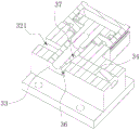
37-second guiding inclined plane 38-third guiding inclined plane 39-fourth guiding inclined plane
21-first driving source 22-first mounting plate 23-first pivot seat
24-first limiting swing arm 25-abutting block 321-mounting groove
40-base 50-main shaft device 60-horizontal positioning device
100-clamping jig 51-vertical frame 52-lifting mechanism
53-main shaft processing mechanism 61-first linear mechanism 62-second linear mechanism
521-lifting driving component 522-movable connecting plate 523-mounting seat
524-first fillet means 525-second fillet means 621-inclined end face
54-reinforcing rib.
Detailed Description
Reference will now be made in detail to embodiments of the present invention, examples of which are illustrated in the accompanying drawings, wherein like or similar reference numerals refer to the same or similar elements or elements having the same or similar function throughout. The embodiments described below with reference to fig. 1-13 are exemplary and intended to be used to illustrate embodiments of the present invention and should not be construed as limiting the invention.
In the description of the embodiments of the present invention, it should be understood that the terms "length", "width", "up", "down", "front", "back", "left", "right", "vertical", "horizontal", "top", "bottom", "inner", "outer", etc. indicate orientations or positional relationships based on those shown in the drawings, and are only for convenience in describing the embodiments of the present invention and simplifying the description, but do not indicate or imply that the device or element referred to must have a particular orientation, be constructed and operated in a particular orientation, and thus, should not be construed as limiting the present invention.
Furthermore, the terms "first", "second" and "first" are used for descriptive purposes only and are not to be construed as indicating or implying relative importance or implicitly indicating the number of technical features indicated. Thus, a feature defined as "first" or "second" may explicitly or implicitly include one or more of that feature. In the description of the embodiments of the present invention, "a plurality" means two or more unless specifically limited otherwise.
In the embodiments of the present invention, unless otherwise explicitly specified or limited, the terms "mounted," "connected," "fixed," and the like are to be construed broadly, e.g., as being fixedly connected, detachably connected, or integrated; can be mechanically or electrically connected; either directly or indirectly through intervening media, either internally or in any other relationship. Specific meanings of the above terms in the embodiments of the present invention can be understood by those of ordinary skill in the art according to specific situations.
In an embodiment of the present invention, as shown in fig. 1 to 13, a machining center structure is provided, which includes a machine base 40, a spindle device 50, a horizontal positioning device 60 and a clamping fixture 100; the spindle device 50 comprises a vertical frame 51, a lifting mechanism 52 and a spindle machining mechanism 53, wherein the vertical frame 51 is arranged on the machine base 40, the lifting mechanism 52 is arranged on the side wall of the vertical frame 51, and the spindle machining mechanism 53 is arranged at the output end of the lifting mechanism 52; the horizontal positioning device 60 comprises a first linear mechanism 61 and a second linear mechanism 62, the first linear mechanism 61 is arranged on the machine base 40 and is positioned at one side of the lifting mechanism 52, the second linear mechanism 62 is arranged at the output end of the first linear mechanism 61, the driving directions of the first linear mechanism 61 and the second linear mechanism 62 are mutually vertical, and the moving paths of the output ends of the first linear mechanism 61 and the second linear mechanism 62 pass below the output end of the lifting mechanism 52; the clamping jig 100 is arranged at the output end of the second linear mechanism 62 and is used for clamping a base station bottom plate to be processed; the lifting mechanism 52 comprises a lifting driving assembly 521, a moving connecting plate 522 and a mounting seat 523, wherein the lifting driving assembly 521 is arranged on the side wall of the vertical frame 51, the driving direction of the lifting driving assembly 521 is arranged along the length direction of the vertical frame 51, the moving connecting plate 522 is arranged at the output end of the lifting driving assembly 521, the moving connecting plate 522 is vertically arranged, the mounting seat 523 is fixedly connected to the moving connecting plate 522, a reinforcing rib 54 is arranged between the side wall of the mounting seat 523 and the moving connecting plate 522, a first fillet mechanism 524 is arranged on the circumferential edge of the reinforcing rib 54, and a second fillet mechanism 525 is arranged at the end part of the reinforcing rib 54 connected with the moving connecting plate 522 and the mounting seat 523; the number of the reinforcing ribs 54 is multiple, and the multiple groups of the reinforcing ribs 54 are uniformly distributed at two ends of the mounting seat 523 at intervals.
Specifically, the working principle of the machining center structure is as follows: installing a base station bottom plate to be processed on the clamping jig 100; the first linear mechanism 61 drives the second linear mechanism 62 to move linearly, the second linear mechanism 62 is positioned right below the output end of the spindle machining mechanism 53, and the second linear mechanism 62 drives the clamping fixture 100 to move linearly, so that the base station bottom plate installed on the clamping fixture 100 is aligned with the output end of the spindle machining mechanism 53; the lifting mechanism 52 drives the main shaft processing mechanism 53 to move linearly along the vertical direction, so that the output end of the main shaft processing mechanism 53 moves to the processing surface of the base station bottom plate to be processed; the output end of the spindle machining mechanism 53 operates to machine the base station bottom plate; after the processing is finished, the first linear mechanism 61 is matched with the second linear mechanism 62 to drive the clamping jig 100 to move to a preset blanking station; blanking, a reinforcing rib 54 is arranged between the side wall of the mounting seat 523 and the movable connecting plate 522, a first round angle mechanism 524 is arranged at the circumferential edge of the reinforcing rib 54, and a second round angle mechanism 525 is arranged at the end part of the reinforcing rib 54 connected with the movable connecting plate 522 and the mounting seat 523, compared with the processing center in the prior art, the main shaft and the driving mechanism are fixedly locked and connected by adopting a screw structure, the connection stability is poor, the looseness is easy to occur, the deviation in the moving process of the main shaft is caused, the positioning precision is influenced, the processing precision is low, the processing efficiency of the processing center is influenced, and the technical problem which is not beneficial to the development of enterprises is solved. The positioning precision of the main shaft is greatly improved, so that the machining precision and the machining efficiency of the machining center structure are improved, and enterprise development is facilitated.
In another embodiment of the present invention, the cross section of the reinforcing rib 54 is configured in a right-angled triangle structure, two right-angled edges of the reinforcing rib 54 are respectively and fixedly connected to the movable connecting plate 522 and the mounting seat 523, the first fillet mechanism 524 is formed on the edge between the two reinforcing ribs 54, and the second fillet mechanism 525 is formed on the bevel edge of the reinforcing rib 54.
In another embodiment of the present invention, the second linear mechanism 62 includes a second linear component and a movable base, the movable base is disposed at the output end of the first linear mechanism 61, the second linear component is disposed on the movable base, and the clamping fixture 100 is disposed at the output end of the second linear component; wherein, the radial cross-section that removes the seat is Contraband type column structure, it has the die cavity that is used for the installation to remove the seat and go up the shaping the second straight line subassembly, the intermediate position that removes the seat with the output of first straight line mechanism 61 is connected, the bottom that removes the seat narrows so that towards its both ends border position from its central point gradually the bottom shaping that removes the seat has the distribution to be in the slope terminal surface 621 of first straight line mechanism 61 both sides, the bottom cross-section that removes the seat sets up for the toper structure, and the both ends that remove the seat are the narrow end, save space, reduce the space ratio of machining center structure, reduce the weight that removes the seat, reduce the load of first straight line mechanism 61, are favorable to improving the drive efficiency of first straight line mechanism 61, and then improve the location precision that removes the seat.
Another embodiment of the present invention provides a machining center control method, executed by the above-mentioned machining center structure, including the steps of:
s100: installing a base station bottom plate to be processed on the clamping jig 100;
s200: the first linear mechanism 61 drives the second linear mechanism 62 to move linearly, so that the second linear mechanism 62 is positioned right below the output end of the spindle machining mechanism 53, and the second linear mechanism 62 drives the clamping fixture 100 to move linearly, so that the base station bottom plate mounted on the clamping fixture 100 is aligned with the output end of the spindle machining mechanism 53;
s300: the lifting mechanism 52 drives the spindle machining mechanism 53 to move linearly in the vertical direction, so that the output end of the spindle machining mechanism 53 moves to the machining surface of the base plate of the base station to be machined.
S400: the output end of the spindle machining mechanism 53 operates to machine the base station bottom plate.
S500: after the machining is finished, the first linear mechanism 61 is matched with the second linear mechanism 62 to drive the clamping jig 100 to move to a preset blanking station;
s600: and (6) blanking.
Specifically, because the machining center control method is executed by the machining center structure, compared with the machining center in the prior art, the main shaft and the driving mechanism are fixedly locked and connected by adopting a screw structure, the connection stability is poor, the looseness is easy, the deviation in the moving process of the main shaft is caused, the positioning precision is influenced, the machining precision is low, the machining efficiency of the machining center is influenced, and the enterprise development is not facilitated.
The first linear mechanism 61, the second linear assembly and the lifting driving assembly 521 are all servo motors and screw rod pair linear sliding tables.
In another embodiment of the present invention, the clamping fixture 100 includes a base 10, a first limiting mechanism 20 and a second limiting mechanism 30; the base 10 is provided with a base plate mounting position for accommodating a base plate of the base station; the number of the first limiting mechanisms 20 is three, three groups, the first limiting mechanisms 20 are all arranged on the base 10 and located on one side of the installation position, and the first limiting mechanisms 20 are used for pressing down the base plate of the base station.
The number of the second limiting mechanisms 30 is three, the second limiting mechanisms 30 include a second driving source 31, a second mounting seat 32, a first transmission block 33, a second transmission block 34 and a first lifting block 35, the second mounting seat 32 is arranged on the base 10 and located on the other side of the mounting position, the second mounting seat 32 and the first limiting mechanism 20 are symmetrically arranged with the base plate mounting position as a center, the second mounting seat 32 is provided with an X-direction mounting hole, a Y-direction mounting hole and a Z-direction mounting hole, the X-direction mounting hole, the Y-direction mounting hole and the Z-direction mounting hole are perpendicular to each other and are communicated with each other, the second mounting seat 32 is arranged on the base 10, the second driving source 31 is arranged on a side wall of the second mounting seat 32, an output end of the second driving source 31 can extend into the X-direction mounting hole, the first transmission block 33 is slidably connected in the X-direction mounting hole, the second transmission block 34 is connected in the Y-direction mounting hole in a sliding manner, the first lift block 35 is connected in the Z-direction mounting hole in a sliding manner, the output end of the second drive source 31 is connected with the first transmission block 33 in a driving manner, and the top end of the first lift block 35 extends to the outer side of the Z-direction mounting hole and can abut against the bottom of the base station bottom plate.
The end surfaces of the first transmission block 33 and the second transmission block 34, which are opposite to each other, are respectively provided with a first guide inclined surface 36 and a second guide inclined surface 37, the inclined directions and the inclined angles of the first guide inclined surface 36 and the second guide inclined surface 37 are the same, the end parts of the second transmission block 34 and the first jacking block 35, which are opposite to each other, are respectively provided with a third guide inclined surface 38 and a fourth guide inclined surface 39, and the inclined directions and the inclined angles of the third guide inclined surface 38 and the fourth guide inclined surface 39 are the same.
The three groups of first limiting mechanisms 20 and the three groups of second limiting mechanisms 30 are uniformly distributed on two sides of the bottom plate mounting position at intervals, one group of second limiting mechanisms 30 are arranged between every two adjacent groups of first limiting mechanisms 20, and one group of first limiting mechanisms 20 are arranged between every two adjacent groups of second limiting mechanisms 30.
As shown in fig. 1 to 13, in this embodiment, three sets of the first limiting mechanisms 20 are distributed on two sides of the base 10 mounting position in a triangular structure, three sets of the second limiting mechanisms 30 are distributed on two sides of the base 10 mounting position in an inverted triangular structure, and the first limiting mechanisms 20 and the second limiting mechanisms 30 are reasonably complementary to each other.
Specifically, the working principle of the clamping jig 100 is as follows: placing a base station bottom plate to be processed on the bottom plate installation position; any one of the first limiting mechanisms 20 drives the output end thereof to move towards the upper end of the base station bottom plate, so that the output end of the first limiting mechanism 20 is abutted against and presses the base station bottom plate; the second driving source 31 drives the first transmission block 33 to move along the length direction of the X-direction mounting hole; the first transmission block 33 drives the second transmission block 34 to move through the first guide inclined surface 36 and the second guide inclined surface 37, and the second transmission block 34 drives the first lifting block 35 to move upwards through the third guide inclined surface 38 and the fourth guide inclined surface 39, so that the top end of the first lifting block 35 abuts against and lifts the base station bottom plate; repeating the steps until the output ends of all the first limiting mechanisms 20 and all the second limiting mechanisms 30 extend and abut against the preset positions; the linear assembly in the machining center structure moves the clamping jig 100 to a preset position, and a machining main shaft part of the machining center structure machines a base station bottom plate limited on the clamping jig 100; compared with the base station bottom plate processing jig in the prior art which adopts a simple clamping jaw or sucking disc structure to fix the base station bottom plate, the base station bottom plate processing jig has the technical problems that the clamping effect is unstable and the production efficiency is seriously influenced, the base station bottom plate clamping jig 100 provided by the embodiment of the invention adopts the first limiting mechanism 20 and the second limiting mechanism 30 which are symmetrical in pairs to respectively press or abut against the upper end and the lower end of the base station bottom plate, and because the second limiting mechanism 30 and the first limiting mechanism 20 are respectively arranged between the adjacent first limiting mechanism 20 and the adjacent second limiting mechanism 30 and are in a state of complementary clamping positions, the upper end and the lower end of the edge position of the base station bottom plate are respectively pressed in reasonable directions, thereby saving the parts of clamping equipment, saving the cost, simultaneously, having simple structure, being convenient to install, having obvious clamping effect and strong stability, and being beneficial to improving the processing efficiency of the base station bottom plate, is beneficial to the development of enterprises.
In another embodiment of the present invention, as shown in fig. 1 to 13, the first limiting mechanism 20 includes a first driving source 21, a first mounting plate 22, a first pivot seat 23 and a first limiting swing arm 24, the first driving source 21 is provided on the base 10, the first mounting plate 22 is provided at an upper end of the first driving source 21, the output end of the first driving source 21 passes through the first mounting plate 22 and extends upward, the first pivot seat 23 is disposed on one side of the first mounting plate 22 close to the bottom plate mounting position, the middle position of the first limit swing arm 24 is pivoted with the first pivoting seat 23, one end of the first limit swing arm 24 is pivoted with the output end of the first driving source 21, the other end of the first limiting swing arm 24 extends to the upper part of the base plate mounting position to be pressed against the upper part of the base station base plate; specifically, the working principle of the first limiting mechanism 20 is as follows: the output of first driving source 21 drives up, makes the tip of first spacing swing arm 24 is down beat and butt in the upper end of basic station bottom plate, realizes pressing the effect, and this simple structure, the mount pad 523 of being convenient for presses the effect and is showing, is favorable to improving the practicality of this centre gripping tool 100.
As shown in fig. 1 to 13, in another embodiment of the present invention, a contact block 25 is disposed at an end of the first limiting swing arm 24 close to the bottom plate mounting location, a cross section of the contact block 25 is configured in a hammer shape, and an end of the contact block 25 close to the bottom plate mounting location is a narrow end, specifically, a tapered structure is adopted to reduce a space occupation ratio of the contact block 25, so that an overall structure of the first limiting mechanism 20 is optimized, and the practicability of the clamping fixture 100 is further improved.
As shown in fig. 1 to 13, in another embodiment of the present invention, a buffering arc-shaped end surface is disposed at a lower end of the abutting block 25, and the buffering arc-shaped end surface structure is favorable for preventing a rigid end surface from impacting an edge position of a base station bottom plate, so as to affect product quality, further improve a clamping effect, and improve a processing yield.
As shown in fig. 1 to 13, in another embodiment of the present invention, a chamfer structure is disposed at an end of the abutting block 25 close to the bottom plate mounting position, and particularly, an obtuse angle structure is formed on an end surface of the abutting block 25 by adopting the chamfer structure, so as to prevent a sharp edge of the abutting block 25 from scratching the bottom plate of the base station, further ensure product quality, and improve processing yield.
As shown in fig. 1 to 13, in another embodiment of the present invention, the first limiting swing arm 24 is pivotally connected to the first pivot base 23 through a pivot connection block, a through slot is disposed at a middle position of the first limiting swing arm 24, a pivot rod is disposed in the through slot, two ends of the pivot connection block are respectively provided with a pivot hole, and two ends of the pivot connection block are respectively rotatably connected to the pivot rod and an upper end of the pivot connection base through the corresponding pivot holes.
As shown in fig. 1 to 13, in another embodiment of the present invention, an installation groove 321 for installing the second transmission block 34 is disposed at an end of the second installation seat 32, the installation groove 321 penetrates through the second installation seat 32 and the Y-direction installation hole, the size of the installation groove 321 is matched with the second transmission block 34, and the installation groove 321 is adopted to facilitate higher installation convenience for the second transmission block 34, and the structural design is ingenious and reasonable, which facilitates improvement of the dismounting efficiency of the second limiting mechanism 30.
As shown in fig. 1 to 13, in another embodiment of the present invention, a limiting block is disposed at a top end of the second mounting seat 32, one end of the limiting block extends to one side above the Z-direction mounting hole, a step structure is disposed at a top end of the first lift block 35, a cross section of a top end portion of the first lift block 35 is disposed in an "L" shape, a cross section of an extending portion of the limiting block is disposed in an inverted "L" shape, and the limiting block can abut against and fit with the step structure.
As shown in fig. 1 to 13, another embodiment of the present invention provides a method for clamping a base plate of a base station, which is performed by the clamping fixture 100, and includes the following steps:
s100: placing a base station bottom plate to be processed on the bottom plate installation position;
s200: any one of the first limiting mechanisms 20 drives the output end thereof to move towards the upper end of the base station bottom plate, so that the output end of the first limiting mechanism 20 is abutted against and presses the base station bottom plate;
s300: the second driving source 31 disposed at the symmetrical position of the first stopper mechanism 20 in step S200 drives the first transmission block 33 to move in the longitudinal direction of the X-direction mounting hole; the first transmission block 33 drives the second transmission block 34 to move through the first guide inclined surface 36 and the second guide inclined surface 37, and the second transmission block 34 drives the first lifting block 35 to move upwards through the third guide inclined surface 38 and the fourth guide inclined surface 39, so that the top end of the first lifting block 35 abuts against and lifts the base station bottom plate.
S400: repeating S200-S300 until the output ends of all the first limiting mechanisms 20 and all the second limiting mechanisms 30 extend and abut against preset positions;
specifically, because the control method of the processing center is executed by the clamping jig 100, compared with the base station bottom plate processing jig in the prior art which adopts a simple clamping jaw or sucking disc structure to fix the base station bottom plate, the technical problems of unstable clamping effect and serious influence on production efficiency exist, the clamping jig 100 for the base station bottom plate of the communication base station provided by the embodiment of the invention adopts the first limiting mechanism 20 and the second limiting mechanism 30 which are symmetrical in pairs to press or prop against the upper end and the lower end of the base station bottom plate respectively, and because the second limiting mechanism 30 and the first limiting mechanism 20 are arranged between the adjacent first limiting mechanism 20 and the adjacent second limiting mechanism 30 respectively and are in a state of complementary clamping positions, the upper end and the lower end of the edge position of the base station bottom plate are respectively pressed in reasonable directions, thereby saving parts of clamping equipment, saving cost, and simultaneously, having simple structure, the installation of being convenient for, the centre gripping effect is showing moreover, and stability is strong, is favorable to improving the machining efficiency of basic station bottom plate, is favorable to the enterprise development.
In the above embodiment of the present invention, the first drive source 21 and the second drive source 31 are both thin cylinders.
The above description is only for the purpose of illustrating the preferred embodiments of the present invention and is not to be construed as limiting the invention, and any modifications, equivalents and improvements made within the spirit and principle of the present invention are intended to be included within the scope of the present invention.
Claims (8)
1. A machining center structure, comprising:
a machine base;
the spindle device comprises a vertical frame, a lifting mechanism and a spindle machining mechanism, wherein the vertical frame is arranged on the base, the lifting mechanism is arranged on the side wall of the vertical frame, and the spindle machining mechanism is arranged at the output end of the lifting mechanism;
the horizontal positioning device comprises a first linear mechanism and a second linear mechanism, the first linear mechanism is arranged on the base and is positioned on one side of the lifting mechanism, the second linear mechanism is arranged at the output end of the first linear mechanism, the driving directions of the first linear mechanism and the second linear mechanism are mutually vertical, and the moving paths of the output ends of the first linear mechanism and the second linear mechanism pass below the output end of the lifting mechanism;
the clamping jig is arranged at the output end of the second linear mechanism and is used for clamping the base station bottom plate to be processed;
the lifting mechanism comprises a lifting driving assembly, a movable connecting plate and a mounting seat, the lifting driving assembly is arranged on the side wall of the vertical frame, the driving direction of the lifting driving assembly is arranged along the length direction of the vertical frame, the movable connecting plate is arranged at the output end of the lifting driving assembly, the movable connecting plate is vertically arranged, the mounting seat is fixedly connected onto the movable connecting plate, reinforcing ribs are arranged between the side wall of the mounting seat and the movable connecting plate, first fillet mechanisms are arranged on the circumferential edges of the reinforcing ribs, and second fillet mechanisms are arranged at the end parts of the reinforcing ribs, which are connected with the movable connecting plate and the mounting seat;
the clamping jig comprises a base, three groups of first limiting mechanisms and three groups of second limiting mechanisms; the base is provided with a bottom plate mounting position for accommodating a bottom plate of the base station; the three groups of first limiting mechanisms are arranged on the base and located on one side of the mounting position, and the first limiting mechanisms are used for pressing the base station bottom plate downwards; the three groups of second limiting mechanisms are the same as the first limiting mechanisms in number and comprise second driving sources, second mounting seats, first transmission blocks, second transmission blocks and first lifting blocks, the second mounting seats are arranged on the base and located on the other side of the mounting positions, the second mounting seats and the first limiting mechanisms are symmetrically arranged by taking the bottom plate mounting positions as centers, the second mounting seats are provided with X-direction mounting holes, Y-direction mounting holes and Z-direction mounting holes, every two of the X-direction mounting holes, the Y-direction mounting holes and the Z-direction mounting holes are perpendicular and communicated with each other, the second mounting seats are arranged on the base, the second driving sources are arranged on the side walls of the second mounting seats, the output ends of the second driving sources can extend into the X-direction mounting holes, and the first transmission blocks are connected in the X-direction mounting holes in a sliding manner, the second transmission block is connected in the Y-direction mounting hole in a sliding mode, the first jacking block is connected in the Z-direction mounting hole in a sliding mode, the output end of the second driving source is connected with the first transmission block in a driving mode, and the top end of the first jacking block extends to the outer side of the Z-direction mounting hole and can abut against the bottom of the base station bottom plate;
the end surfaces of the first transmission block and the second transmission block, which are opposite to each other, are respectively provided with a first guide inclined surface and a second guide inclined surface, the inclined directions and the inclined angles of the first guide inclined surface and the second guide inclined surface are the same, the end parts of the second transmission block and the first jacking block, which are opposite to each other, are respectively provided with a third guide inclined surface and a fourth guide inclined surface, and the inclined directions and the inclined angles of the third guide inclined surface and the fourth guide inclined surface are the same;
three groups of first limiting mechanisms and three groups of second limiting mechanisms are uniformly distributed on two sides of the bottom plate mounting position at intervals, one group of second limiting mechanisms is arranged between two adjacent groups of first limiting mechanisms, and one group of first limiting mechanisms is arranged between two adjacent groups of second limiting mechanisms;
first stop gear includes first driving source, first mounting panel, first pin joint seat and first spacing swing arm, first driving source sets up on the base, first mounting panel sets up the upper end of first driving source, the output of first driving source passes first mounting panel and up extend, first pin joint seat sets up first mounting panel is close to one side of bottom plate installation position, the intermediate position of first spacing swing arm with the pin joint of first pin joint seat, the one end of first spacing swing arm with the output pin joint of first driving source, the other end of first spacing swing arm extends to the top of bottom plate installation position is in order to be used for supporting to press in the top of base station bottom plate.
2. The machining center structure according to claim 1, wherein: the cross-section of strengthening rib is the setting of right angle triangle-shaped shape structure, two right angle borders of strengthening rib respectively with remove the connecting plate with mount pad fixed connection, first fillet mechanism shaping in on the border between two of strengthening rib, second fillet mechanism shaping in on the hypotenuse of strengthening rib.
3. The machining center structure according to claim 1, wherein: the second linear mechanism comprises a second linear assembly and a moving seat, the moving seat is arranged at the output end of the first linear mechanism, the second linear assembly is arranged on the moving seat, and the clamping jig is arranged at the output end of the second linear assembly;
the radial cross section of the moving seat is of an Contraband-shaped structure, the moving seat is formed with a cavity for mounting the second linear assembly, the middle position of the moving seat is connected with the output end of the first linear mechanism, and the bottom of the moving seat is gradually narrowed from the center position to the edge positions of the two ends of the moving seat so that the bottom of the moving seat is formed with inclined end faces distributed on two sides of the first linear mechanism.
4. The machining center structure according to claim 1, wherein: the first limiting swing arm is close to the end of the bottom plate installation position and is provided with a butt joint block, the cross section of the butt joint block is in a hammer-shaped structure, and the butt joint block is close to the end of the bottom plate installation position and is a narrow end.
5. The machining center structure according to claim 4, wherein: the lower extreme of butt joint piece is provided with buffering arc terminal surface, the butt joint piece is close to the tip of bottom plate installation position is provided with the chamfer structure.
6. The machining center structure according to claim 5, wherein: the first limiting swing arm is pivoted with the first pivoting seat through a pivoting block, a through groove is formed in the middle of the first limiting swing arm, a pivoting rod is arranged in the through groove, two ends of the pivoting block are respectively provided with a pivoting hole, and two ends of the pivoting block are respectively in rotating connection with the pivoting rod and the upper end of the pivoting seat through the corresponding pivoting holes; the tip of second mount pad is provided with and is used for the installation the mounting groove of second transmission piece, the mounting groove runs through the second mount pad with Y is to the mounting hole, the size of a dimension of mounting groove with second transmission piece adaptation.
7. The machining center structure according to claim 6, wherein: a limiting block is arranged at the top end of the second mounting seat, one end of the limiting block extends to one side above the Z-direction mounting hole, and a step structure is arranged at the top end of the first jacking block;
the cross section of the top end part of the first jacking block is of an L-shaped structure, the cross section of the extending part of the limiting block is of an inverted L-shaped structure, and the limiting block can be abutted and matched with the step structure.
8. A machining center control method is characterized in that: the machining center structure as claimed in any one of claims 1 to 7, comprising the steps of:
s100: installing a base station bottom plate to be processed on the clamping jig;
s200: the first linear mechanism drives the second linear mechanism to move linearly, the second linear mechanism is positioned under the output end of the spindle machining mechanism, and the second linear mechanism drives the clamping fixture to move linearly, so that a base station bottom plate arranged on the clamping fixture is aligned with the output end of the spindle machining mechanism;
s300: the lifting mechanism drives the main shaft machining mechanism to move linearly along the vertical direction, so that the output end of the main shaft machining mechanism moves to the machining surface of the base plate of the base station to be machined;
s400: the output end of the main shaft machining mechanism operates to machine a base station bottom plate;
s500: after the machining is finished, the first linear mechanism is matched with the second linear mechanism to drive the clamping jig to move to a preset blanking station;
s600: and (6) blanking.
Priority Applications (1)
| Application Number | Priority Date | Filing Date | Title |
|---|---|---|---|
| CN202010987213.3A CN112222868B (en) | 2020-09-18 | 2020-09-18 | Machining center structure and machining center control method |
Applications Claiming Priority (1)
| Application Number | Priority Date | Filing Date | Title |
|---|---|---|---|
| CN202010987213.3A CN112222868B (en) | 2020-09-18 | 2020-09-18 | Machining center structure and machining center control method |
Publications (2)
| Publication Number | Publication Date |
|---|---|
| CN112222868A CN112222868A (en) | 2021-01-15 |
| CN112222868B true CN112222868B (en) | 2021-09-07 |
Family
ID=74107231
Family Applications (1)
| Application Number | Title | Priority Date | Filing Date |
|---|---|---|---|
| CN202010987213.3A Active CN112222868B (en) | 2020-09-18 | 2020-09-18 | Machining center structure and machining center control method |
Country Status (1)
| Country | Link |
|---|---|
| CN (1) | CN112222868B (en) |
Citations (9)
| Publication number | Priority date | Publication date | Assignee | Title |
|---|---|---|---|---|
| CN204209418U (en) * | 2014-10-31 | 2015-03-18 | 福建常青精密机械有限公司 | Novel vertical machining center structure |
| KR20160049335A (en) * | 2014-10-27 | 2016-05-09 | 두산인프라코어 주식회사 | Machine tool |
| CN107498320A (en) * | 2017-08-17 | 2017-12-22 | 上海诺倬力机电科技有限公司 | Processing center of numerical-control machine tool |
| CN207387070U (en) * | 2017-10-18 | 2018-05-22 | 东莞盛翔精密金属有限公司 | Universal CNC Precision Machinings jig base |
| CN208196165U (en) * | 2018-04-03 | 2018-12-07 | 东莞市乔锋机械有限公司 | Highly-efficient processing center machine |
| CN209648121U (en) * | 2018-12-28 | 2019-11-19 | 东莞市捷正精密机械有限公司 | A kind of machining center |
| CN209998753U (en) * | 2019-06-15 | 2020-01-31 | 广东捷弘数控智能科技有限公司 | vertical machining center |
| CN111283439A (en) * | 2018-12-07 | 2020-06-16 | 黄石市金球机械制造厂 | Workbench suitable for machining large-sized workpiece plane |
| CN210967842U (en) * | 2019-11-17 | 2020-07-10 | 杭州耿杰电器有限公司 | Motor processing tool table |
-
2020
- 2020-09-18 CN CN202010987213.3A patent/CN112222868B/en active Active
Patent Citations (9)
| Publication number | Priority date | Publication date | Assignee | Title |
|---|---|---|---|---|
| KR20160049335A (en) * | 2014-10-27 | 2016-05-09 | 두산인프라코어 주식회사 | Machine tool |
| CN204209418U (en) * | 2014-10-31 | 2015-03-18 | 福建常青精密机械有限公司 | Novel vertical machining center structure |
| CN107498320A (en) * | 2017-08-17 | 2017-12-22 | 上海诺倬力机电科技有限公司 | Processing center of numerical-control machine tool |
| CN207387070U (en) * | 2017-10-18 | 2018-05-22 | 东莞盛翔精密金属有限公司 | Universal CNC Precision Machinings jig base |
| CN208196165U (en) * | 2018-04-03 | 2018-12-07 | 东莞市乔锋机械有限公司 | Highly-efficient processing center machine |
| CN111283439A (en) * | 2018-12-07 | 2020-06-16 | 黄石市金球机械制造厂 | Workbench suitable for machining large-sized workpiece plane |
| CN209648121U (en) * | 2018-12-28 | 2019-11-19 | 东莞市捷正精密机械有限公司 | A kind of machining center |
| CN209998753U (en) * | 2019-06-15 | 2020-01-31 | 广东捷弘数控智能科技有限公司 | vertical machining center |
| CN210967842U (en) * | 2019-11-17 | 2020-07-10 | 杭州耿杰电器有限公司 | Motor processing tool table |
Also Published As
| Publication number | Publication date |
|---|---|
| CN112222868A (en) | 2021-01-15 |
Similar Documents
| Publication | Publication Date | Title |
|---|---|---|
| CN212311462U (en) | Steady hardware mould processing clamp | |
| CN112222868B (en) | Machining center structure and machining center control method | |
| CN218284277U (en) | Multi-angle welding frock for sheet metal component | |
| CN212885922U (en) | Tenon type standard knot main chord angle steel welding system | |
| CN2917923Y (en) | Cramping apparatus for processing dome head welding groove | |
| CN219747072U (en) | Quick firm anchor clamps of milling machine ram dovetail seat processing | |
| CN215033056U (en) | Sheet metal machining device capable of achieving efficient positioning | |
| CN213319974U (en) | Automobile headlamp machining device | |
| CN220161802U (en) | Four-axis clamp for processing thin cylinder body | |
| CN219665813U (en) | Clamp and machine tool | |
| CN218927036U (en) | Rotary clamping tool | |
| CN217751011U (en) | Robot base tool centre gripping frock of polishing | |
| CN220761758U (en) | Lying clamp suitable for machining large workpiece | |
| CN215846629U (en) | Assembly welding jig of flat fork robot | |
| CN214721879U (en) | Automatic clamping and positioning structure of large-scale clamp body | |
| CN218460963U (en) | Milling flutes anchor clamps frock for axle | |
| CN216706689U (en) | Boring clamping and aligning device | |
| CN220838102U (en) | Multi-angle milling device for machining | |
| CN218856211U (en) | CR450 gallows crouches and processes clamping device | |
| CN217166679U (en) | Alloy steel frog milling positioning device | |
| CN219704650U (en) | Manual positioning tool for arc castings | |
| CN219310692U (en) | Quick positioner that spanner processing was used | |
| CN216706635U (en) | Polishing welding equipment based on metal part machining | |
| CN216939367U (en) | Pre-buried seat processing equipment of tower crane | |
| CN217798500U (en) | Non-standard wedge workpiece machining reference structure of die |
Legal Events
| Date | Code | Title | Description |
|---|---|---|---|
| PB01 | Publication | ||
| PB01 | Publication | ||
| SE01 | Entry into force of request for substantive examination | ||
| SE01 | Entry into force of request for substantive examination | ||
| GR01 | Patent grant | ||
| GR01 | Patent grant |