CN112219080A - Through-air drying system and method with hot air injection - Google Patents
Through-air drying system and method with hot air injection Download PDFInfo
- Publication number
- CN112219080A CN112219080A CN201980029585.0A CN201980029585A CN112219080A CN 112219080 A CN112219080 A CN 112219080A CN 201980029585 A CN201980029585 A CN 201980029585A CN 112219080 A CN112219080 A CN 112219080A
- Authority
- CN
- China
- Prior art keywords
- air
- heated
- heated air
- tad
- heating element
- Prior art date
- Legal status (The legal status is an assumption and is not a legal conclusion. Google has not performed a legal analysis and makes no representation as to the accuracy of the status listed.)
- Pending
Links
Images
Classifications
-
- F—MECHANICAL ENGINEERING; LIGHTING; HEATING; WEAPONS; BLASTING
- F26—DRYING
- F26B—DRYING SOLID MATERIALS OR OBJECTS BY REMOVING LIQUID THEREFROM
- F26B21/00—Arrangements or duct systems, e.g. in combination with pallet boxes, for supplying and controlling air or gases for drying solid materials or objects
- F26B21/02—Circulating air or gases in closed cycles, e.g. wholly within the drying enclosure
- F26B21/04—Circulating air or gases in closed cycles, e.g. wholly within the drying enclosure partly outside the drying enclosure
-
- F—MECHANICAL ENGINEERING; LIGHTING; HEATING; WEAPONS; BLASTING
- F26—DRYING
- F26B—DRYING SOLID MATERIALS OR OBJECTS BY REMOVING LIQUID THEREFROM
- F26B13/00—Machines and apparatus for drying fabrics, fibres, yarns, or other materials in long lengths, with progressive movement
- F26B13/10—Arrangements for feeding, heating or supporting materials; Controlling movement, tension or position of materials
- F26B13/14—Rollers, drums, cylinders; Arrangement of drives, supports, bearings, cleaning
- F26B13/16—Rollers, drums, cylinders; Arrangement of drives, supports, bearings, cleaning perforated in combination with hot air blowing or suction devices, e.g. sieve drum dryers
-
- F—MECHANICAL ENGINEERING; LIGHTING; HEATING; WEAPONS; BLASTING
- F26—DRYING
- F26B—DRYING SOLID MATERIALS OR OBJECTS BY REMOVING LIQUID THEREFROM
- F26B21/00—Arrangements or duct systems, e.g. in combination with pallet boxes, for supplying and controlling air or gases for drying solid materials or objects
- F26B21/001—Drying-air generating units, e.g. movable, independent of drying enclosure
-
- F—MECHANICAL ENGINEERING; LIGHTING; HEATING; WEAPONS; BLASTING
- F26—DRYING
- F26B—DRYING SOLID MATERIALS OR OBJECTS BY REMOVING LIQUID THEREFROM
- F26B21/00—Arrangements or duct systems, e.g. in combination with pallet boxes, for supplying and controlling air or gases for drying solid materials or objects
- F26B21/06—Controlling, e.g. regulating, parameters of gas supply
- F26B21/10—Temperature; Pressure
-
- F—MECHANICAL ENGINEERING; LIGHTING; HEATING; WEAPONS; BLASTING
- F26—DRYING
- F26B—DRYING SOLID MATERIALS OR OBJECTS BY REMOVING LIQUID THEREFROM
- F26B21/00—Arrangements or duct systems, e.g. in combination with pallet boxes, for supplying and controlling air or gases for drying solid materials or objects
- F26B21/06—Controlling, e.g. regulating, parameters of gas supply
- F26B21/12—Velocity of flow; Quantity of flow, e.g. by varying fan speed, by modifying cross flow area
-
- F—MECHANICAL ENGINEERING; LIGHTING; HEATING; WEAPONS; BLASTING
- F26—DRYING
- F26B—DRYING SOLID MATERIALS OR OBJECTS BY REMOVING LIQUID THEREFROM
- F26B23/00—Heating arrangements
- F26B23/02—Heating arrangements using combustion heating
-
- F—MECHANICAL ENGINEERING; LIGHTING; HEATING; WEAPONS; BLASTING
- F26—DRYING
- F26B—DRYING SOLID MATERIALS OR OBJECTS BY REMOVING LIQUID THEREFROM
- F26B3/00—Drying solid materials or objects by processes involving the application of heat
- F26B3/02—Drying solid materials or objects by processes involving the application of heat by convection, i.e. heat being conveyed from a heat source to the materials or objects to be dried by a gas or vapour, e.g. air
- F26B3/04—Drying solid materials or objects by processes involving the application of heat by convection, i.e. heat being conveyed from a heat source to the materials or objects to be dried by a gas or vapour, e.g. air the gas or vapour circulating over or surrounding the materials or objects to be dried
Abstract
Systems and methods for drying or bonding materials are described. The material to be dried or combined may be passed through a through-air dryer (TAD) (or other dryer). Some of the air output by the TAD may be recirculated to be re-conveyed through the material. As the air is recirculated, it is heated and mixed to a desired temperature for drying or bonding. A separate hot air injection system may heat the ambient air and/or air exhausted by the TAD and inject the heated air into the recirculation air.
Description
Background
"through-air technology" is a term used to describe systems and methods that enable heated air to flow through a nonwoven web for the purpose of drying or bonding fibers or filaments. Examples include: drying of nonwoven products (e.g., tea bags and specialty papers); drying and curing the glass fiber mat, the filter paper and the resin-treated nonwoven fabric; thermal bonding and drying of the spunbond nonwoven; drying the hydroentangled web; a thermally bonded geotextile with or without bicomponent fibers; drying and curing the interlayer grade; and a thermally bonded absorbent core having fusible binder fibers. Drying of tissue paper is a particularly important application of the through-air technique, and the systems and methods associated with through-air drying are generally referred to by using the acronym "TAD". Some air-through systems use natural gas burners to deliver thermal energy to the system. That is, in order to expose the material to air at a temperature that can dry or bond the material, the air penetration system may use a natural gas burner to heat the air.
Disclosure of Invention
As discussed in the background section above, TAD systems represent an important class of broader through-air technology systems. The invention disclosed herein is applicable to various through-air technology systems and methods, but for simplicity, the invention may be discussed herein in the context of TAD systems and methods. One significant challenge associated with TAD systems is the introduction of a large amount of energy (e.g., 20 to 60MW) into the TAD system without compromising performance, controllability and reliability, scaling of the TAD system, pressure drop, air mixing, conditioning, and achieving the target air temperature for the TAD from common heat exchange equipment.
The present disclosure provides TAD systems having a reduced carbon footprint. The TAD system according to the present disclosure mitigates climate change associated with the use of fossil fuels. TAD systems may use alternative energy sources or other carbon neutralizing sources, such as hydroelectric power, biofuels, solar power, wind power, heat recovery, steam/condensation heat exchange, and the like.
The TAD system according to the present disclosure has several advantages, including: staged energy input from various heat sources and heat exchange devices; reducing the carbon footprint; a self-contained energy transfer system that allows operation of the TAD system in a conventional mode with the natural gas burner as a backup; the ability to recover low grade heat (low grade heat) from the TAD exhaust; the ability to regulate energy input from several preferred sources including burners or electric heat exchangers; ease of maintenance, including accessibility (e.g., isolation of the hot air injection system from the TAD system allows maintenance of the hot air injection system while the TAD system is operating); maintaining temperature and flow uniformity in the TAD supply; a variety of energy sources may be used to utilize the temperature ranges best suited for the various sources (e.g., recovering heat from TAD exhausts, steam, condensate, hot oil, electricity, and other streams); the ability to add additional heat sources and heat exchangers without the need for TAD system redesign or rebuilding (e.g., hot air injection system components may be supplemented in series with already installed TAD system components); the existing TAD system can be retrofitted; and the ability to use exhaust vacuum venting as a supplement to the incoming hot air injection system.
In accordance with the present disclosure, a hot air injection system using an alternative energy source, including a carbon neutralization source, is configured to deliver hot air to one or more TAD systems. A TAD system according to the present disclosure may include a combustor system that may be used regardless of whether the hot air injection system is operating.
Certain aspects of a TAD system according to the present disclosure may operate in accordance with currently known TAD system operation. For example, known fan speeds and combustor output may be used to regulate the air temperature input to the hood of the TAD and the flow of air in the hood. By injecting air from the hot air injection system into the TAD system airflow, as described herein, the burner energy required to heat the air to the desired temperature may be reduced and the fan speed may be varied as compared to known techniques.
The hot air injection system may be operated with the burner at low fire output, at which time the burner is still responsible for controlling the drying temperature. The hot air injection system may alternatively be left inoperative, resulting in the TAD system operating in a conventional standalone mode of operation.
When used with a TAD system, the hot air injection system according to the present disclosure may provide sufficient flexibility. The TAD system may be used independently of the hot air injection system or together with the hot air injection system. This configuration allows for complete isolation of the different air systems, thereby allowing access, maintenance, start-up and shut-down independently of each other. Furthermore, such a system configuration allows for seamless transitions between normal operation without hot air injection and operation with hot air injection without compromising production (e.g., drying of the material).
One aspect of the present disclosure is directed to a system for drying (or bonding) a material. The system includes a first air stream configured by a fired heater, a mixing element, a shroud, and a perforated cylinder. The combustion heater is configured to generate first heated air. The mixing element operates on the first heated air to produce a second heated air at a desired temperature. Examples of mixing elements suitable for use in conjunction with the present disclosure are described in U.S. patent No. 7,861,437, the disclosure of which is incorporated herein by reference in its entirety. The hood receives the second heated air. The perforated cylinder is surrounded by a shroud and outputs cooling air. The system also includes a second air flow configured with at least one heating element and at least one fan in fluid communication with the at least one heating element. The at least one heating element is configured to generate third heated air. The at least one fan causes the third heated air to be injected into the first air stream. The combustion heater operates on at least a portion of the third heated air and the cooling air to produce first heated air.
Another aspect of the present disclosure is directed to a method for drying a material. The method comprises the following steps: generating cooling air, generating first heated air using at least one heating element; combining at least a portion of the cooling air and the first heated air to produce mixed air; heating the mixed air using a combustion heater to produce second heated air; mixing the second heated air to produce third heated air at a desired temperature; and exposing the third heated air to the material to produce cooled air.
Although the present disclosure is described with respect to a through-air system including a dryer and a bonder, other systems may be used, such as yankee air systems, flat plate dryers, float dryers, and other dryers and ovens.
Drawings
For a more complete understanding of this disclosure, reference is now made to the following descriptions taken in conjunction with the accompanying drawing.
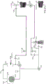
Fig. 1 is a schematic view of a single TAD system with a hot air injection system according to an embodiment of the present disclosure.
Fig. 2 is a schematic diagram of a dual TAD system with a hot air injection system according to an embodiment of the present disclosure.
Fig. 3 is a process flow diagram illustrating operation of a single TAD system with a hot air injection system according to an embodiment of the present disclosure.
Detailed Description
The present disclosure includes at least one TAD system coupled to a hot air injection system, for example, for reducing carbon emissions and delivering the energy required to evaporate moisture from a paper web (e.g., tissue paper) or other similar product (e.g., nonwoven). The hot air injection system may provide (e.g., inject) hot air to the TAD system at a suitably elevated temperature to increase the temperature of the air output by the TAD of one or more systems to a desired supply air drying temperature. The desired supply air may be supplied to the material in the TAD to be dried. The flow of cooling air output from the TAD, circulated through the components to heat the cooling air to a desired temperature, and the insertion of the desired temperature air into the TAD may be referred to herein as "recirculated air" or "recirculated air".
In accordance with the present disclosure, conventional TAD system designs may remain largely unaffected by the inclusion of a hot air injection system. The hot air injection system may be introduced into the TAD system in a manner that mixes with the recirculation air of the TAD system. The mixing of the recirculation air of the TAD system with the air supplied by the hot air injection system may take place before or after the main recirculation fan of the TAD system. The mixing of the recirculated air of the TAD system with the air supplied by the hot air injection system may also take place before or after the air heater section of the TAD system. For example, the hot air injection system may inject heated air into the recirculated air of the TAD system upstream of the fired heater, relative to the flow of the recirculated air. By way of further example, the hot air injection system may inject heated air into the recirculated air of the TAD system downstream of the fired heater, relative to the flow of the recirculated air. In a preferred embodiment, the mixing of the recirculated air of the TAD system with the air supplied by the hot air injection system may take place between the main fan and the air heater section of the TAD system.
The hot air injection system may be implemented separately from the TAD system, such that the TAD system may be operated without the hot air injection system operating. This enables the TAD system to remain operational while maintenance is being performed on the hot air injection system and/or due to unplanned shutdowns of the hot air injection system.
Multiple heat sources may be used to heat the air input to the hot air injection system. The air input to the hot air injection system may be from ambient air (e.g., fresh air from the ambient environment of the hot air system), TAD system exhaust, and/or other sources. The air input to the hot air injection system may originate from a single source (e.g., ambient air only or TAD system exhaust only), or may be a combination of air from multiple sources (e.g., a combination of ambient air and TAD system exhaust).
The fan may be used to draw air into the hot air injection system before or after any combination of heat exchangers or introduction of other air sources. The air is gradually heated to the desired injection temperature by a combination of heat sources and heat exchangers. One arrangement includes TAD system exhaust mixed with preheated ambient air, which then continues through a fan, then through a steam heat exchanger, an oil heat exchanger, and an electric heat exchanger (or bank of exchangers). The foregoing arrangement is illustrative. Accordingly, one skilled in the art will appreciate that other arrangements for heating air in a hot air injection system may be used. The purpose of the sequence of heating elements in the hot air injection system may be to step up the air temperature, taking advantage of the maximum (e.g., optimal) temperature output of each heating element. For example, a steam heat exchanger may heat air to about 182 ℃, an oil heat exchanger may heat air at about 182 ℃ to about 290 ℃, and an electric heat exchanger may heat air at about 290 ℃ to about 450 ℃ or higher.
FIG. 1 illustrates an example configuration of a single TAD system with a hot air injection system. The lines shown in fig. 1 and 2 represent possible gas flows for a system according to the present disclosure.
The TAD system may include a TAD 100, the TAD 100 including a perforated (e.g., foraminous) cylinder 104 at least partially surrounded by a hood 106, a main fan 108, an air heater 110, and a mixer 112. Although only one main fan 108, one air heater 110, and one mixer 112 are shown, it should be understood by those skilled in the art that a TAD system may include more than one main fan 108, more than one air heater 110, and/or more than one mixer 112.
The material to be dried is carried along the perforated cylinder 104 through the hood 106. Heated air at a desired temperature is input to the hood 106 and exposed to the material to be dried. The air that travels through the material to dry the material is cooler than when it first contacts the material. The cooling air traveling through the material then travels through the pores in the porous cylinder 104 and is output from the TAD 100 as cooling air (or exhaust).
Some of the cooling air output from the TAD 100 may be recirculated to the TAD 100. As shown, some of the cooling air output from the TAD 100 may be delivered to an air heater 110 by a main fan 108. The air heater 110 may heat the cooling air by burning fossil fuel. The air heater 110 heats the cooling air and outputs the heated air to the mixer 112. The air heater 110 may include various types of air heating elements known in the art and not yet created. For example, the air heater 110 may include one or more electric heaters, one or more steam coils, one or more glycol/air heat exchangers, and/or one or more combustion-based heating elements. The air heating elements implemented in the air heater 110 may depend on the system configuration and the desired temperature of the air output by the air heater 110. The mixer 112 receives heated air from the air heater 110 and outputs heated air at a desired temperature, which is input to the TAD 100 (and more specifically to the hood 106).
Due to operation of the exhaust fan 114, some of the cooling air output from the TAD 100 may be output from the TAD system to the hot air injection system. Some of the cooling air output from the TAD 100 may be input to the air-to-glycol heat exchanger 116, wherein the cooling air (cooled relative to the air input to the TAD 110, but not cooled to ambient temperature) heats the air to the glycol of the glycol heat exchanger 116. After heating the glycol, the air may be output to the environment of the system via a tower of the air-to-glycol heat exchanger 116. The output air may be relatively cool and in a saturated state (e.g., 100% relative humidity). This output of air enables the system to remove evaporated water with the air and also enables the system to keep the air system balanced.
The hot air injection system may include one or more air heating elements. For example, the hot air injection system may include a glycol-to-air heat exchanger 118 and an electric heater 120. The coils of the glycol-to-air heat exchanger 118 may receive heated glycol from the air-to-glycol heat exchanger 116 (e.g., glycol heated by cooling air output by the TAD 100 and conveyed through the exhaust fan 114). The hot air injection system may also include one or more other heating elements, such as steam coils, other heating elements known in the art, and heating elements not yet created.
The heating elements of the hot air injection system may be arranged and configured to step up the temperature of the air, with a maximum (e.g., optimal) temperature output of each heating element. For example, air in a hot air injection system may be first exposed to a steam heat exchanger that may heat the air to about 182 ℃. This air at about 182 c may be exposed to an oil heat exchanger that may further heat the air to about 290 c. The air at about 290 ℃ may be exposed to an electrical heat exchanger that may further heat the air to about 450 ℃ or higher. The foregoing arrangement of the heating elements is merely illustrative. As such, those skilled in the art will appreciate that the number, type, and arrangement of the heating elements of the hot air injection system may depend on the system configuration and the desired temperature of the air output by the hot air injection system.
The hot air injection system may also include a fan 122, the fan 122 causing air in the hot air injection system to be injected into the TAD system. The fan 122 may be located upstream (with respect to airflow) of all of the heating elements of the hot air injection system, between the heating elements of the hot air injection system (as shown), or downstream (with respect to airflow) of all of the heating elements of the hot air injection system.
In one example, the air input to the hot air injection system may be pure ambient air received from the ambient environment of the hot air injection system. This may be accomplished by closing the damper 130 and opening the damper 140. In another example, the air input to the hot air injection system may be pure cooling air output from the TAD system, optionally passed through an exhaust fan 114 before being input to the hot air injection system. This may be accomplished by closing the damper 140 and opening the damper 130. In yet another example, the air input to the hot air injection system may be a combination of ambient air of the ambient environment of the hot air injection system and cooling air output by the TAD system. This may be accomplished by opening various dampers (130/140). The ratio of combined ambient air and cooling air input to the air injection system may depend on various factors, including the system configuration (e.g., the amount each damper is open or closed), the air velocity, the desired temperature of the air output by the hot air injection system, and other considerations.
The TAD 100, the main fan 108, the air heater 110, and the mixer 112, as well as the ducting coupling the aforementioned components together, may form a first air flow. The heating element of the hot air injection system and the fan 122 may form a second air stream that is different from the first air stream.
Heated air generated by the heating elements of the hot air injection system may be injected (through the use of the fan 122 and the opening of the damper 126/134) into the first air stream of the TAD system. The heated air produced by the hot air injection system may be injected into the airflow of the TAD system at various locations depending on the system configuration and requirements. For example, heated air generated by the hot air injection system may be injected into the airflow of the TAD system between the main fan 108 and the air heater 110 (as shown), between the air heater 110 and the mixer 112, or other desired location.
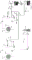
FIG. 2 illustrates an example configuration of a dual TAD system with a hot air injection system. The first TAD system includes a TAD 100, the TAD 100 including a perforated cylinder 104 at least partially surrounded by a hood 106, a main fan 108, an air heater 110, and a mixer 112. The second TAD system includes a TAD 200, the TAD 200 including a perforated cylinder 204 at least partially surrounded by a hood 202, a main fan 208, an air heater 210, and a mixer 212. Although only one main fan 208, one air heater 210, and one mixer 212 are shown, it should be understood by those skilled in the art that a TAD system may include more than one main fan 208, more than one air heater 210, and/or more than one mixer 212. As described above with reference to fig. 1, the material is dried by the first TAD 100 and the second TAD 200.
Similar to fig. 1, the system of fig. 2 is configured to recirculate some of the cooling air output from the TAD 100 to the TAD 100. Further, some of the cooling air output from the TAD 100 may be output from the TAD system as exhaust air. This air may be input to the hot air injection system via the exhaust fan 114.
The same is true of the TAD 200, as some of the air output from the TAD 200 may be recirculated to the TAD 200 (after the air is recirculated through the main fan 208, the air heater 210, and the mixer 212), and some of the cooling air may be input to the hot air injection system via the exhaust fan 206. In one example, the exhaust fan 206 injects air from the TAD 200 into the air stream between the exhaust fan 114 and the air-to-glycol heat exchanger 116 and the hot air injection system.
The system may be configured such that the hot air output from the hot air injection system may be input to both TADs (100/200) (e.g., when dampers 134, 214, and 126 are open and damper 142 is closed), one of the TADs (100/200) (e.g., when dampers 134 and 214 are open and dampers 126 and 142 are closed, or when dampers 126 and 134 are open and dampers 214 and 142 are closed), or none of the TADs (100/200) (e.g., when at least dampers 126 and 214 are closed and damper 142 is open). The decision of how to direct the hot air output by the hot air injection system may depend on maintenance considerations, the desired temperature of the air to be inserted into the TAD (e.g., certain materials may be effectively dried at a reduced temperature compared to other materials, such that hot air does not have to be injected from the hot air injection system into the TAD air stream in this use case), and other considerations.
Fig. 3 illustrates operations performed by a single TAD system with a hot air injection system. Heated air at a desired temperature is directed into the hood 106 of the TAD 100 to cause (302) the heated air at the desired temperature to dry the material on the porous cylinder 104, thereby causing the heated air at the desired temperature to become cooling air.
The at least one heating element of the hot air injection system (e.g., the glycol-to-air heat exchanger 118 and/or the electric heater 120) generates (304) first heated air from ambient air, some or all of the cooling air output by the TAD 100, or a combination of ambient air and some or all of the cooling air output by the TAD 100.
The hot air injection system injects the first heated air into the air stream of the TAD system. In one example, the first heated air is combined (306) with at least a portion of the cooling air output by the TAD 100, producing mixed air. In this embodiment, the air heater 110 heats (308) the mixed air using combustion to produce second heated air. The second heated air is then operated by the mixer 112 to mix (310) the second heated air into heated air of a desired temperature for drying the material.
The process described with reference to fig. 3 may be performed by a dual TAD system as shown in fig. 2. Further, while the steps of the method are described above in a particular order, those skilled in the art will appreciate that the steps may be performed in a different order and/or that some steps may be removed or omitted without departing from the disclosure.
Since the hot air injection system is physically coupled to the TAD system, there is a possibility that combustible gas may infiltrate the hot air injection system while the TAD system is operating. Thus, according to NFPA-86, a pre-ignition purge may be performed to evacuate at least four air volumes prior to starting the hot air injection system. The TAD system may include improved controls to ensure that the pre-ignition purge includes additional interlocks to verify that no combustible gases are available to enter the TAD system from the hot air injection system. Complete separation of the TAD system and the hot air injection system may be achieved by using a dual block and bleed arrangement that uses multiple isolation and bleed dampers.
The pre-ignition purge of the hot air injection system may be controlled by a dedicated hot air injection control system or a plant Distributed Control System (DCS). The control system ensures that the hot air injection system is isolated from the TAD system, all hot air injection lines are purged, ambient air can enter the hot air injection system, and pre-ignition purge flow is measured and verified. During the pre-ignition purge, movement of air in the hot air injection system may be facilitated by the fan 122, and a flow meter may be used to demonstrate airflow.
After the pre-ignition purge is complete, and once the TAD system is in operation and steady state conditions, the hot air injection system may be activated. To open the hot air injection system, all bleed dampers (e.g., 128/132 and 216/220, depending on the system configuration) of the hot air injection system may be closed, resulting in a single pass airflow from the glycol to the air heat exchanger 118 to the split stack (reverse stack) being established. Once the single-pass airflow is established, the electric heater 120 may begin desired operation, resulting in the temperature of the air output by the electric heater 120 (and, more generally, the hot air injection system) remaining constant (or relatively constant) thereafter.
Dampers (126 and 214, depending on the system configuration) are located at the junction between the ducts of the hot air injection system and the ducts of the TAD system and may be opened to allow heated air to be injected from the hot air injection system into the airflow of the TAD system. At the same time (or substantially the same time), the damper 142 of the bypass stack of the hot air injection system may be closed. Upon injecting heated air of the hot air injection system into the air flow of the TAD system, cooling air (e.g., exhaust air) of the TAD system may be introduced into the hot air injection system to recover exhaust energy of the TAD system.
The hot air injection system is flexible in that it allows a variable combination of ambient air and TAD system cooling air to be input thereto. For example, in a dual TAD system configuration, one or more dampers may be open to allow only cooling air for a first TAD to be input to the hot air injection system, one or more dampers may be open to allow only cooling air for a second TAD to be input to the hot air injection system, or one or more dampers may be open to allow cooling air for both TADs to be input to the hot air injection system. When the damper is open to allow cooling air for both TADs to be input to the hot air injection system, the damper may be open to allow more cooling air for the first TAD than for the second TAD, more cooling air for the second TAD than for the first TAD, or equal amounts of cooling air for the first and second TADs to be input to the hot air injection system. The cooling air of the TAD system may be input to the hot air injection system downstream of the glycol to air heat exchanger 118 but upstream of the electric heater 120 with respect to the air flow of the hot air injection system. More preferably, the cooling air of the TAD system may be input to the hot air injection system downstream of the glycol to air heat exchanger 118 but upstream of the electric heater 120 and fan 122 with respect to the flow of the hot air injection system.
Once the hot air injection system air is injected into the TAD system airflow, the heating performed by the air heater (110/210) and the speed of the main fan (108/208) may be adjusted to maintain the temperature of the air in the hood (106/202) at a desired temperature (e.g., the temperature experienced in the hood 106/202 prior to the injection of air by the hot air injection system). Thus, it should be appreciated that injecting hot air by the hot air injection system may reduce the amount of heating that needs to be performed by the air heater (110/210). In embodiments where the air heater (110/210) operates by combustion of fossil fuels, such a configuration may result in reduced use of fossil fuels.
TAD systems may experience a stock-off condition in which material to be dried (and/or already dried) is quickly removed from the TAD system. It is important to rapidly reduce the temperature of the air input to the hood of the TAD system to a safe limit to avoid thermal damage to the TAD fabric. A TAD fabric refers to a fabric used to convey material to be dried (and/or already dried) through a system.
When the TAD system generates a stock cutoff signal, the TAD control system may close the hot air injection system damper (126 and 214, depending on the system configuration) and open the bypass stack damper 142. This manages the temperature of the hot air injection system's air and electric heater 120 load, which changes during sudden material starvation conditions. Once stock on is initiated and the TAD system assumes steady state conditions, hot air injection system air may be introduced into the TAD system (e.g., by opening one or more dampers (128/214) and closing the dampers 142 of the diversion stacks).
The hot air injection system components may be forced into a safe state when a machine emergency stop command is received. This may include shutting off power to the electric heater 120, stopping the fan 122, closing all isolation dampers (e.g., 126/130/134/136/214/218) of the hot air injection system, opening the damper 142 of the bypass stack, and/or opening all bleed dampers (e.g., 128/132/216/220) of the hot air injection system. The aforementioned damper configuration ensures that there is sufficient natural ventilation through the hot air injection system to prevent overheating of the electric heater 120.
The hot air injection system may be shut down independently of the TAD system. The sequence of closing the hot air injection system may include opening the damper 142 of the diversion stack, closing all isolation dampers (e.g., 126/130/134/136/214/218) of the hot air injection system, opening all bleed dampers (e.g., 128/132/216/220) of the hot air injection system, and/or gradually reducing the power input to the electric heater 120 to zero (e.g., according to a programmed ramp). The speed of the fan 122 may also be gradually reduced (e.g., ramped) until the fan 122 stops.
While the present disclosure has been particularly described, in conjunction with a specific embodiment, it is evident that many alternatives, modifications and variations will be apparent to those skilled in the art in light of the foregoing description. It is therefore contemplated that the appended claims will embrace any such alternatives, modifications and variations as falling within the true spirit and scope of the present disclosure.
Claims (24)
1. A system for drying or bonding materials, comprising:
a first set of components for generating a first air flow, the first set of components comprising:
a combustion heater configured to generate first heated air;
a mixing element operating on the first heated air to produce second heated air at a desired temperature;
a hood receiving the second heated air; and
a perforated cylinder surrounded by the shroud, the perforated cylinder outputting cooling air;
a second set of components for generating a second air flow, the second set of components comprising:
at least one heating element configured to generate third heated air; and
at least one fan in fluid communication with the at least one heating element, the at least one fan causing the third heated air to be injected into the first air stream.
2. The system of claim 1, wherein the air input to the at least one heating element is ambient air.
3. The system of claim 1, wherein the air input to the at least one heating element is at least a second portion of the cooling air.
4. The system of claim 3, wherein ambient air is passed through the glycol-to-air heat exchanger of the at least one heating element.
5. The system of claim 1, wherein the air input to the at least one heating element is a combination of ambient air and at least a second portion of the cooling air.
6. The system of claim 1, further comprising:
a third set of components for generating a third air flow, the third set of components comprising:
a second combustion heater configured to generate fourth heated air;
a second mixing element operating on the fourth heated air to produce fifth heated air at a desired temperature;
a second hood that receives the fifth heated air; and
a second perforated cylinder surrounded by the second shroud, the second perforated cylinder outputting a second cooling air.
7. The system of claim 6, wherein the air input to the at least one heating element is a combination of at least a portion of the cooling air and at least a portion of the second cooling air.
8. The system of claim 4, wherein at least a portion of the cooling air is used to heat glycol in an air-to-glycol heat exchanger, the heated glycol being supplied to coils of the glycol-to-air heat exchanger.
9. The system of claim 1, wherein the second set of components further comprises:
a glycol-to-air heat exchanger that produces intermediate heated air; and
an electric heater operating on the intermediate heated air to generate the third heated air.
10. The system of claim 1, wherein injecting the second heated air into the first air stream reduces an amount of combustion that needs to be performed by the fired heater.
11. The system of claim 1, wherein the combustion heater operates on at least a portion of the third heated air and the cooling air to produce the first heated air.
12. The system of claim 1, wherein the mixing element operates on the first heated air and the third heated air to produce the second heated air at the desired temperature.
13. A method for drying or bonding materials, comprising:
generating a first air flow by:
the generation of the cooling air is carried out,
generating a first heated air using at least a first heating element,
mixing the first heated air to produce second heated air at a desired temperature, and
exposing the second heated air to the material to produce the cooling air;
generating a second air flow by:
generating third heated air using at least a second heating element, an
Injecting the third heated air into the first air stream.
14. The method of claim 13, further comprising:
ambient air is input to the at least second heating element.
15. The method of claim 13, further comprising:
inputting at least a portion of the cooling air to the at least second heating element.
16. The method of claim 13, further comprising:
passing ambient air through a glycol-to-air heat exchanger to produce fourth heated air, the at least second heating element comprising the glycol-to-air heat exchanger.
17. The method of claim 13, further comprising:
a combination of ambient air and at least a portion of the cooling air is input to the at least second heating element.
18. The method of claim 13, further comprising:
generating a third air flow by:
generating second cooling air;
generating fourth heated air using at least a third heating element;
mixing the fourth heated air to produce fifth heated air at a desired temperature; and
exposing the fifth heated air to a second material to produce the second cooling air.
19. The method of claim 18, further comprising:
inputting a combination of at least a portion of the cooling air and at least a portion of the second cooling air to the at least second heating element.
20. The method of claim 16, further comprising:
a glycol to glycol heat exchanger to heat air using at least a portion of the cooling air; and
supplying the heated glycol to a coil of the glycol-to-air heat exchanger.
21. The method of claim 13, further comprising:
passing ambient air through a glycol to an air heat exchanger to produce intermediate heated air; and
passing the intermediate heated air through the electric heater to produce the third heated air.
22. The method of claim 13, wherein:
injecting the third heated air into the first air stream reduces the amount of combustion that needs to be performed by the at least first heating element.
23. The method of claim 13, further comprising:
combining at least a portion of the third heated air and the cooling air to produce combined air; and
inputting the combined air into the at least first heating element.
24. The method of claim 13, further comprising:
mixing the first heated air and the third heated air to produce the second heated air at the desired temperature.
Applications Claiming Priority (3)
| Application Number | Priority Date | Filing Date | Title |
|---|---|---|---|
| US201862665120P | 2018-05-01 | 2018-05-01 | |
| US62/665120 | 2018-05-01 | ||
| PCT/US2019/014505 WO2019212612A1 (en) | 2018-05-01 | 2019-01-22 | Through air drying systems and methods with hot air injection |
Publications (1)
| Publication Number | Publication Date |
|---|---|
| CN112219080A true CN112219080A (en) | 2021-01-12 |
Family
ID=68384956
Family Applications (1)
| Application Number | Title | Priority Date | Filing Date |
|---|---|---|---|
| CN201980029585.0A Pending CN112219080A (en) | 2018-05-01 | 2019-01-22 | Through-air drying system and method with hot air injection |
Country Status (6)
| Country | Link |
|---|---|
| US (2) | US10712090B2 (en) |
| EP (1) | EP3788312A4 (en) |
| JP (2) | JP7431174B2 (en) |
| CN (1) | CN112219080A (en) |
| CA (1) | CA3092024A1 (en) |
| WO (1) | WO2019212612A1 (en) |
Families Citing this family (1)
| Publication number | Priority date | Publication date | Assignee | Title |
|---|---|---|---|---|
| WO2019212612A1 (en) | 2018-05-01 | 2019-11-07 | Valmet, Inc. | Through air drying systems and methods with hot air injection |
Citations (7)
| Publication number | Priority date | Publication date | Assignee | Title |
|---|---|---|---|---|
| WO2002022948A1 (en) * | 2000-09-18 | 2002-03-21 | Kimberly-Clark Worldwide, Inc. | Method of drying a web |
| US20040118009A1 (en) * | 2002-12-20 | 2004-06-24 | Metso Paper Usa, Inc. | Method and apparatus for adjusting a moisture profile in a web |
| CN103453751A (en) * | 2013-08-30 | 2013-12-18 | 合肥禾盛新型材料有限公司 | High heat waste gas energy source utilization system |
| CN103574630A (en) * | 2012-07-19 | 2014-02-12 | 中国电力工程顾问集团华东电力设计院 | Method for improving temperature of smoke discharged by chimney of thermal power plant, smoke heating system and thermal power generation unit |
| CN103821025A (en) * | 2013-12-16 | 2014-05-28 | 广西大学 | Black liquor gasification-fueled paper web hot air drying method and system device |
| CN204963517U (en) * | 2015-09-10 | 2016-01-13 | 丁德华 | Air source constant temperature and humidity vermicelli stoving heat recovery unit |
| CN105258518A (en) * | 2015-11-11 | 2016-01-20 | 中国中轻国际工程有限公司 | Heat recovery process and system of flue gas |
Family Cites Families (31)
| Publication number | Priority date | Publication date | Assignee | Title |
|---|---|---|---|---|
| US3303576A (en) * | 1965-05-28 | 1967-02-14 | Procter & Gamble | Apparatus for drying porous paper |
| CA937045A (en) * | 1969-08-18 | 1973-11-20 | Dominion Engineering Works | Integrated drying processes and apparatus |
| GB1519265A (en) * | 1975-04-09 | 1978-07-26 | Valmet Oy | Method and apparatus for treatment of a web in order to adjust the moisture content thereof |
| CA1066498A (en) * | 1976-01-21 | 1979-11-20 | Dominion Engineering Works Limited | Paper web streak drying system |
| DE3120738A1 (en) * | 1981-05-25 | 1982-12-09 | Windmöller & Hölscher, 4540 Lengerich | METHOD AND DEVICE FOR DRYING PRINTED OR COATED FILMS. |
| US4365425A (en) * | 1981-06-09 | 1982-12-28 | Scott Paper Company | Controlled curing of air-permeable bonded webs |
| FI79156C (en) * | 1988-03-08 | 1989-11-10 | Valmet Paper Machinery Inc | Procedure in an integrated IR dryer / yankee cover and IR dryer / yankee cover. |
| US5465504A (en) * | 1994-04-08 | 1995-11-14 | James River Paper Company, Inc. | System for modifying the moisture profile of a paper web |
| US5416979A (en) * | 1994-04-11 | 1995-05-23 | James River Paper Company, Inc. | Paper web dryer and paper moisture profiling system |
| US5553391A (en) * | 1995-06-05 | 1996-09-10 | Bakalar; Sharon F. | Method and apparatus for heat treating webs |
| US5584190A (en) * | 1995-09-25 | 1996-12-17 | Cole; Ronald A. | Freezer with heated floor and refrigeration system therefor |
| DE19806427A1 (en) * | 1998-02-17 | 1999-08-19 | Fleissner Maschf Gmbh Co | Air mixer for static mixing of two air flows |
| FI110622B (en) * | 1998-04-30 | 2003-02-28 | Metso Paper Inc | A method and apparatus for improving the drying capacity of a blanket of a Yankee cylinder |
| US6314659B1 (en) * | 1999-12-14 | 2001-11-13 | Valmet Inc. | Device and method for protecting a carrying fabric |
| US6383391B1 (en) * | 2000-07-28 | 2002-05-07 | Dais-Analytic Corporation | Water-and ion-conducting membranes and uses thereof |
| FI111092B (en) * | 2001-06-26 | 2003-05-30 | Metso Automation Oy | A method for blowing drying gas against a paper web and a paper machine blow dryer |
| FI20020159A (en) * | 2002-01-29 | 2003-07-30 | Metso Paper Inc | Surface shaping apparatus and method using the apparatus for finishing coated or uncoated fibrous web |
| US6869506B2 (en) * | 2002-11-22 | 2005-03-22 | Metso Paper Karlstad Aktiebolag (Ab) | Apparatus for dewatering a paper web and associated system and method |
| US6910283B1 (en) | 2003-12-19 | 2005-06-28 | Kimberly-Clark Worldwide, Inc. | Method and system for heat recovery in a throughdrying tissue making process |
| CN101052853B (en) * | 2004-03-02 | 2010-06-16 | 贝卡尔特股份有限公司 | Infrared drying device for conveying fabrics |
| SE529130C2 (en) * | 2004-05-26 | 2007-05-08 | Metso Paper Karlstad Ab | Paper machine for manufacturing fiber web of paper, comprises clothing that exhibits three-dimensional structure for structuring fiber web |
| AT413709B (en) * | 2004-06-28 | 2006-05-15 | Andritz Ag Maschf | DEVICE FOR CONTINUOUS DRYING OF A FIBROUS WEB |
| US7861437B2 (en) | 2006-02-27 | 2011-01-04 | Metso Paper Usa, Inc. | System and method for mixing distinct air streams |
| US7716850B2 (en) * | 2006-05-03 | 2010-05-18 | Georgia-Pacific Consumer Products Lp | Energy-efficient yankee dryer hood system |
| JP4818063B2 (en) | 2006-10-17 | 2011-11-16 | 花王株式会社 | Bulky paper manufacturing method |
| DE102012010776A1 (en) * | 2011-06-03 | 2012-12-06 | Claus-Dieter Grapengiesser | Oven useful for heating, annealing, tempering or annealing coils, profiles or pipes running through the oven, comprises radiation absorber or several radiation absorbers arranged in a rear of oven or at the beginning of re-cooling device |
| DE102011113837A1 (en) * | 2011-09-21 | 2013-03-21 | Trützschler Nonwovens Gmbh | Heating system for heating a gaseous treatment medium for a dryer |
| FR3016374B1 (en) * | 2014-01-15 | 2016-01-29 | Andritz Perfojet Sas | METHOD AND INSTALLATION FOR DRYING A WETWATER |
| ITUB20155480A1 (en) * | 2015-11-11 | 2017-05-11 | Coramtex Srl | FABRIC DRYER MACHINE AND FABRIC DRYING METHOD |
| JP6667353B2 (en) * | 2016-04-12 | 2020-03-18 | デュプロ精工株式会社 | Wet paper drying method and used paper recycling processing device |
| WO2019212612A1 (en) * | 2018-05-01 | 2019-11-07 | Valmet, Inc. | Through air drying systems and methods with hot air injection |
-
2019
- 2019-01-22 WO PCT/US2019/014505 patent/WO2019212612A1/en unknown
- 2019-01-22 JP JP2020561050A patent/JP7431174B2/en active Active
- 2019-01-22 US US16/253,830 patent/US10712090B2/en active Active
- 2019-01-22 CN CN201980029585.0A patent/CN112219080A/en active Pending
- 2019-01-22 CA CA3092024A patent/CA3092024A1/en active Pending
- 2019-01-22 EP EP19797063.5A patent/EP3788312A4/en active Pending
-
2020
- 2020-06-11 US US16/898,487 patent/US11150019B2/en active Active
-
2024
- 2024-02-01 JP JP2024014003A patent/JP2024036457A/en active Pending
Patent Citations (7)
| Publication number | Priority date | Publication date | Assignee | Title |
|---|---|---|---|---|
| WO2002022948A1 (en) * | 2000-09-18 | 2002-03-21 | Kimberly-Clark Worldwide, Inc. | Method of drying a web |
| US20040118009A1 (en) * | 2002-12-20 | 2004-06-24 | Metso Paper Usa, Inc. | Method and apparatus for adjusting a moisture profile in a web |
| CN103574630A (en) * | 2012-07-19 | 2014-02-12 | 中国电力工程顾问集团华东电力设计院 | Method for improving temperature of smoke discharged by chimney of thermal power plant, smoke heating system and thermal power generation unit |
| CN103453751A (en) * | 2013-08-30 | 2013-12-18 | 合肥禾盛新型材料有限公司 | High heat waste gas energy source utilization system |
| CN103821025A (en) * | 2013-12-16 | 2014-05-28 | 广西大学 | Black liquor gasification-fueled paper web hot air drying method and system device |
| CN204963517U (en) * | 2015-09-10 | 2016-01-13 | 丁德华 | Air source constant temperature and humidity vermicelli stoving heat recovery unit |
| CN105258518A (en) * | 2015-11-11 | 2016-01-20 | 中国中轻国际工程有限公司 | Heat recovery process and system of flue gas |
Also Published As
| Publication number | Publication date |
|---|---|
| JP7431174B2 (en) | 2024-02-14 |
| JP2024036457A (en) | 2024-03-15 |
| US20190339009A1 (en) | 2019-11-07 |
| US10712090B2 (en) | 2020-07-14 |
| EP3788312A4 (en) | 2021-12-29 |
| EP3788312A1 (en) | 2021-03-10 |
| CA3092024A1 (en) | 2019-11-07 |
| US11150019B2 (en) | 2021-10-19 |
| JP2021529921A (en) | 2021-11-04 |
| US20200300544A1 (en) | 2020-09-24 |
| WO2019212612A1 (en) | 2019-11-07 |
Similar Documents
| Publication | Publication Date | Title |
|---|---|---|
| JP5489254B2 (en) | Oxyfuel combustion system and operating method thereof | |
| CN101230985B (en) | Process for operating a thermal generator set with a coal-fired boiler as well as a thermal generator set | |
| KR20000070195A (en) | Combustion turbine with fuel heating system | |
| US20070062175A1 (en) | Flexible flow control device for cogeneration ducting applications | |
| US6957540B1 (en) | Multi-mode complex cycle power plant | |
| US20100062301A1 (en) | System having high-temperature fuel cells | |
| CN101852134A (en) | Improve the power output of power plant and system, the method and apparatus of efficient | |
| JP2010101319A (en) | System and method for heating fuel using exhaust gas recirculation system | |
| JP2024036457A (en) | Through-air drying system and method using hot air introduction | |
| EP2626534A2 (en) | System and method for gas turbine nox emission improvement | |
| CN103453540A (en) | Boiler | |
| US10570823B2 (en) | Heat recovery unit and power plant | |
| KR20020005972A (en) | System for recycling waste heat | |
| JP6407079B2 (en) | Gas turbine system using high-humidity air and its exhaust gas treatment system | |
| KR102485852B1 (en) | Waste gas recirculation in gas and steam combined turbine plants | |
| CN217441684U (en) | Device for reducing smoke discharge temperature of coal-fired boiler by utilizing waste heat of hot primary air | |
| KR102258738B1 (en) | Combustion System Combined with Pressurized Oxygen Combustion and Pulverized Coal Fuel Combustion | |
| JP3713221B2 (en) | Heat source reuse system | |
| JPH0590106U (en) | Coal fired exhaust gas reburn combined cycle plant | |
| DE102018121506A1 (en) | Method for operating a machine for producing or processing a fibrous web, in particular including a calender, and machine or calender for operating according to the method | |
| JPH05288301A (en) | Coal firing discharged gas re-igniting combined cycle plant |
Legal Events
| Date | Code | Title | Description |
|---|---|---|---|
| PB01 | Publication | ||
| PB01 | Publication | ||
| SE01 | Entry into force of request for substantive examination | ||
| SE01 | Entry into force of request for substantive examination |