CN112218694B - Game ring - Google Patents
Game ring Download PDFInfo
- Publication number
- CN112218694B CN112218694B CN201980035752.2A CN201980035752A CN112218694B CN 112218694 B CN112218694 B CN 112218694B CN 201980035752 A CN201980035752 A CN 201980035752A CN 112218694 B CN112218694 B CN 112218694B
- Authority
- CN
- China
- Prior art keywords
- shaped side
- disk
- side cover
- centering
- flywheel mass
- Prior art date
- Legal status (The legal status is an assumption and is not a legal conclusion. Google has not performed a legal analysis and makes no representation as to the accuracy of the status listed.)
- Active
Links
Images


Classifications
-
- A—HUMAN NECESSITIES
- A63—SPORTS; GAMES; AMUSEMENTS
- A63H—TOYS, e.g. TOPS, DOLLS, HOOPS OR BUILDING BLOCKS
- A63H1/00—Tops
-
- A—HUMAN NECESSITIES
- A63—SPORTS; GAMES; AMUSEMENTS
- A63H—TOYS, e.g. TOPS, DOLLS, HOOPS OR BUILDING BLOCKS
- A63H37/00—Jokes; Confetti, streamers, or other dance favours ; Cracker bonbons or the like
-
- A—HUMAN NECESSITIES
- A63—SPORTS; GAMES; AMUSEMENTS
- A63H—TOYS, e.g. TOPS, DOLLS, HOOPS OR BUILDING BLOCKS
- A63H1/00—Tops
- A63H1/24—Tops with illuminating arrangements
Landscapes
- Toys (AREA)
- Engineering & Computer Science (AREA)
- General Engineering & Computer Science (AREA)
Abstract
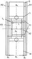
The invention relates to a rotatable playing body suitable for children' S games, comprising a freely rotatable flywheel body (S) arranged between two opposite disk-shaped side covers (K1, K2), wherein the flywheel body (S) has a housing (M) and a centering ball bearing (L), a first disk-shaped side cover (K1) has an outer edge (R1), an outer surface (F1) and a first centering projection (P1) on the inner surface (I1), an opposite second disk-shaped side cover (K2) has an outer edge (R2), an outer surface (F2) and a second centering projection (P387P 2) on the inner surface (I2), and the projections (P1, P2) are suitable for being embedded in the flywheel body (S), wherein the disk-shaped side covers (K1, K2) are movable at the outer edge (R1) and (R2) towards the freely rotatable flywheel body (S), to fix the freely rotatable flywheel mass (S) in its position.
Description
Technical Field
The invention relates to a toy suitable for children' S games, in particular a rotatable playing body, comprising a freely rotatable flywheel mass (S) arranged between two opposite disk-shaped side covers (K1) and (K2), wherein the flywheel mass (S) has a housing (M) and centering ball bearings (L), a first disk-shaped side cover (K1) has an outer edge (R1), an outer surface (F1) and a first centering projection (P1) on the inner surface (I1), an opposite second disk-shaped side cover (K2) has an outer edge (R2), an outer surface (F2) and a second centering projection (P2) on the inner surface (I2), and the projections (P1) and (P2) are suitable for being inserted into the flywheel mass (S), wherein the disk-shaped side covers (K5848) and (K583926) are movable at the outer edge (R1) and at the inner surface (R2) towards the freely rotatable flywheel mass (S), in order to fix the freely rotatable flywheel mass (S) in its position.
Background
Toys are generally objects used for games. Toys are commonly used for children, but it is also not uncommon for adults to use toys. The toy itself and the enjoyment of the game make the toy enjoyable. The exploration of the toy's materials, its functions and its possibilities can be fun. The toy can be used to fully develop the game instinct. The toy can improve the sports interest or communication demand. While toys are not generally necessary or preferred for particular learning purposes, games and toys can provide space and means to promote child development. Physical, cognitive and social skills and abilities can be developed and trained in the game. Playing with a toy that is easy to manipulate is known for the following effects: for example, tension can be eliminated by playing with a toy. Such steerable toys are also used in association with attention deficit hyperactivity disorder (ADHS) or autism. It is also possible to use a toy that is easy to manipulate to overcome bad habits such as smoking, nail biting or to eliminate stress. In order to escape from the pressure state, so-called anti-pressure balls should be mentioned here, for example.
Spinning tops are one of the oldest known toys. A spinning top is a solid body that rotates about an axis. The spinning top is generally free to move, but can also be forced to move in a particular direction by means of an axis. The top is used as a child toy in the following way: it is rotated, for example, on a base plate about a vertically held axis, on which the spinning top runs, and is then held approximately in the direction of this axis for some time. In addition to being a toy, spinning tops have historically been used for gambling and horoscopy. Game tops include, for example, a ringing top, a throwing top, a whipping top, a standing top (spinning top), or a swinging top (gyrotmaster), among others.
Thereby, the rotatable game body is well suited as a toy which can bring about fun and joy and by which a game instinct can be excellently played. The use of rotatable game pieces is an ideal way to eliminate the feeling of boredom created during waiting, for example. Especially the lightweight and portable turnable game body offers an excellent opportunity to bring a possibility of play and thereby the fun created by the game and the fun of the toy anywhere.
Fingertip tops known from the prior art usually have two or three "top arms", for example, the fingertip tops in DE 202017103662U 1, CN 107754323A, CN 107395815 a or US 9,914,063B 1, wherein the fingertip tops must be held centrally and fixed centrally on the lateral covers. CN 107320973 a discloses a fingertip top, which shows a side cover with a central recess, in which a second cover is inserted, which is used to hold the fingertip top fixedly. Fingertip gyros known from the prior art are primarily designed to bring fun and joy to people by means of the rotation of a rotating body.
Disclosure of Invention
The object of the invention is to provide a new toy, in particular a rotatable play ring, which is suitable for children's play and on the outwardly oriented visible surface of the flywheel body between the side covers can be printed, preferably with the design of a play image (spielfigure) and one of the designs can be selected from the rotational movement of the flywheel body by abruptly stopping the flywheel body.
According to the invention, this object is achieved by the technical teaching of the independent claims. Further advantageous embodiments of the invention emerge from the dependent claims, the description, the figures and the examples.
It has surprisingly been found that the object of the invention is achieved by a rotatable playing body suitable for children' S games, comprising a freely rotatable flywheel mass (S) arranged between two opposite disk-shaped side covers (K1) and (K2), wherein the flywheel mass (S) has a housing (M) and a centering ball bearing (L), the first disk-shaped side cover (K1) having an outer edge (R1), an outer surface (F1) and a first centering projection (P1) on an inner surface (I1), the opposite second disk-shaped side cover (K2) having an outer edge (R2), an outer surface (F2) and a second centering projection (P2) on an inner surface (I2), each projection (P1) and (P2) being suitable for being embedded in the flywheel mass (S), wherein the disk-shaped side covers (K1) and (K2) are freely rotatable towards the flywheel mass (S) at the outer edge (R1) and at the inner surface (I962), in order to fix the freely rotatable flywheel mass (S) in its position.
Another embodiment of the invention relates to a rotatable game body suitable for a child game, comprising a freely rotatable flywheel body (S) arranged between two opposite disk-shaped side covers (K1) and (K2), wherein the flywheel body (S) comprises an outer housing (M) with a first central recess (A1) and a centering ball bearing (L) with a second central recess (A2) and which is inserted in the first central recess (A1) of the outer housing (M), wherein the first disk-shaped side cover (K1) has an outer surface (F1) and a first centering projection (P1) on an inner surface (I1), wherein the opposite second disk-shaped side cover (K2) has an outer surface (F2) and a second centering projection (P2) on an inner surface (I2), wherein the first centering projection (P1) is suitable for use, is inserted into the second central recess (A2) of the centering ball bearing (L), while the second centering projection (P2) is adapted to be inserted into the second central recess (A2) of the centering ball bearing (L) and/or into the first centering projection (P1) of the first disk-shaped side cover (K1). Preferably, the two side covers (K1) and (K2) are anchored in the flywheel mass (S) in such a way that the disk-shaped side covers (K1) and (K2) can be moved or pressed against the freely rotatable flywheel mass (S) in order to fix the freely rotatable flywheel mass (S) in its position or to stop it as long as it is rotating.
In other words, the invention relates to a rotatable playing body suitable for children' S games, comprising a freely rotatable flywheel mass (S) arranged between two opposite disk-shaped side covers (K1) and (K2), wherein the flywheel mass (S) comprises an outer housing (M) with a first central recess (A1) and a centering ball bearing (L) with a second central recess (A2) and the centering ball bearing (L) is inserted in the first central recess (A1) of the outer housing (M), the first disk-shaped side cover (K1) has an outer surface (F1) and a first centering projection (P1) on an inner surface (I1), the opposite second disk-shaped side cover (K2) has an outer surface (F2) and a second centering projection (P2) on an inner surface (I2), the first centering projection (P1) is suitable for being inserted in the second central recess (A2) of the centering ball bearing (L), while the second centring lug (P2) is suitable for being inserted into the second central recess (A2) of the centring ball bearing (L) and/or into the first centring lug (P1) of the first discoid side cover (K1).
The invention relates to a rotatable playing body suitable for children' S games, comprising a freely rotatable flywheel mass (S) arranged between two opposite disk-shaped side covers (K1) and (K2), wherein the flywheel mass (S) comprises a housing (M) with a first central recess (A1) and a centering ball bearing (L) with a second central recess (A2) and the centering ball bearing (L) is inserted in the first central recess (A1) of the housing (M), characterized in that the first disk-shaped side cover (K1) has an outer surface (F1) and a first centering projection (P1) on an inner surface (I1), the opposite second disk-shaped side cover (K2) has an outer surface (F2) and a second centering projection (P2) on an inner surface (I2), the first centering projection (P1) is suitable for engaging in the second central ball bearing (A2) of the centering recess (L), while the second centering projection (P2) is adapted to be inserted into the second central recess (A2) of the centering ball bearing (L) and into the first centering projection (P1) of the first disk-shaped side cover (K1).
In other words, the invention relates to a rotatable playing piece suitable for children's games, comprising a freely rotatable flywheel mass arranged between two opposite disk-shaped side covers, wherein the flywheel mass comprises an outer housing with a first central recess and a centering ball bearing with a second central recess and the centering ball bearing is inserted in the first central recess of the outer housing, the two disk-shaped side covers having an outer surface and having a centering projection on the inner surface, respectively, the centering projection being suitable for engaging in the second central recess of the centering ball bearing and/or engaging in the centering projection of the opposite disk-shaped side cover.
In other words, the invention relates to a rotatable playing body suitable for children's games, comprising a freely rotatable flywheel mass arranged between two opposite disk-shaped side covers, wherein the flywheel mass comprises an outer casing with a first central recess and a centering ball bearing with a second central recess and the centering ball bearing is inserted in the first central recess of the outer casing, the outer casing concentrically surrounds the ball bearing centering, the two disk-shaped side covers have outer surfaces and have centering projections on the inner surfaces, respectively, the centering projections being suitable for being inserted in the second central recess of the centering ball bearing and/or in the centering projections of the opposite disk-shaped side covers.
As described above, the anchoring of the side covers in the flywheel mass is configured such that the rotating flywheel mass suddenly stops due to the pressing of the side covers preferably at the outer edge or the flywheel mass is fixed in its position due to the pressing of the side covers preferably at the outer edge.
The invention further relates to a rotatable playing body suitable for children' S games, comprising a freely rotatable flywheel body (S) arranged between two opposite disk-shaped side covers (K1) and (K2), wherein the flywheel body (S) has an outer housing (M) and a centering ball bearing (L), a first disk-shaped side cover (K1) has an outer edge (R1), an outer surface (F1) and a first centering projection (P1) on an inner surface (I1), an opposite second disk-shaped side cover (K2) has an outer edge (R2), an outer surface (F2) and a second centering projection (P2) on the inner surface (I2), and the projections (P1) and (P2) are suitable for being inserted in the flywheel body (S) in a form-locking manner, wherein the disk-shaped side covers (K1) and (K2) are movable at the outer edge (R1) and (R2) towards the freely rotatable flywheel body (S), to fix the freely rotatable flywheel mass (S) in its position.
In other words, the invention therefore relates to a rotatable playing body suitable for children' S games, comprising a freely rotatable flywheel mass (S) arranged between two opposite disk-shaped side covers (K1) and (K2), wherein the flywheel mass (S) has an outer housing (M) and a centering ball bearing (L), a first disk-shaped side cover (K1) having an outer edge (R1), an outer surface (F1) and a first centering projection (P1) on the inner surface (I1), an opposite second disk-shaped side cover (K2) having an outer edge (R2), an outer surface (F2) and a second centering projection (P2) on the inner surface (I2), the first centering projection (P1) being suitable for engaging in a second central recess (a2) of the centering ball bearing (L), and the second centering projection (P2) being suitable for engaging in a second central recess (a2) of the centering recess (L) and/or the first centering projection (P2) of the first disk-shaped side cover (K1) P1), wherein the disc-shaped side covers (K1) and (K2) are movable at the outer edges (R1) and (R2) towards the freely rotatable flywheel mass (S) to fix the freely rotatable flywheel mass (S) in its position.
The term "freely rotatable" is used here as a synonym for "rotatable" or "easy to rotate" and should indicate that a child can start rotating the flywheel mass (S) with little and no effort.
In a preferred embodiment, the rotatable game body has disk-shaped side covers (K1) and (K2) having a diameter in the range of 0.5 to 1.2 times the outer diameter of the flywheel body (S).
In a preferred embodiment of the rotatable game body of the invention, the disk-shaped side covers (K1) and (K2) can be reversibly moved at the outer edges (R1) and (R2) by an action pressure (AF) towards the freely rotatable flywheel mass (S) to fix the freely rotatable flywheel mass (S) in its position. In other words, it is preferred that the disk-shaped side covers (K1) and (K2) can be reversibly moved at the outer edges (R1) and (R2) by the application pressure toward the freely rotatable flywheel mass (S) in order to fix the freely rotatable flywheel mass (S) in its position and to return it again after the pressure applied has disappeared into the position before the pressure application or to be spaced apart from the freely rotatable flywheel mass (S) again as before the pressure application.
In a preferred embodiment of the rotatable game body according to the invention, the freely rotatable flywheel body (S) with the housing (M) is cylindrical and the outer cylindrical surface of the cylindrical flywheel body (S) is flat and printable. It is therefore particularly preferred that the outer radius of the housing (M) of the flywheel mass (S) is constant. Printability of the cylindrical peripheral surface of the flywheel body (S) (for example, printing of a two-dimensional image of a game figure) is important for whether the rotatable game body is suitable as a game ring for a child game. For children 'S games, it is important to bring the rotating flywheel mass (S) to a sudden stop preferably by pressing the two side covers (K1) and (K2) at two opposite points on the outer edges (R1) and (R2) and thereby to select the image pointed to by the markings on the side covers or the user' S finger. But the printability of the outwardly directed surface of the housing of the flywheel body (S) only applies to this surface Although curved in the longitudinal direction according to the cylindrical shape, it is present only if it is flat and not concave or convex in the transverse direction, i.e. parallel to the axis of rotation. The printable visible surface of the flywheel mass (S) housing is at least 25mm per image 2 Preferably 50mm 2 Preferably 70mm 2 Preferably 80mm 2 Preferably 90mm 2 Preferably 100mm 2 Preferably 110mm 2 Preferably 120mm 2 Preferably 130mm 2 Preferably 140mm 2 Preferably 150mm 2 Preferably 160mm 2 Preferably 170mm 2 Preferably 180mm 2 Preferably 190mm 2 Preferably 200mm 2 Preferably 210mm 2 Preferably 220mm 2 。
The housing (M) is preferably cylindrical or preferably has the shape of a triangle, a quadrangle, a pentagon, a hexagon, a heptagon, an octagon or a polygon.
Preferably the first pan-shaped side cover (K1) and/or the second pan-shaped side cover (K2) are cylindrical or have the shape of a triangle, quadrangle, pentagon, hexagon, heptagon, octagon or polygon.
Here, the shape of the triangle, quadrangle, pentagon, hexagon, heptagon, octagon or polygon is preferably a regular polygon.
Furthermore, the freely rotatable flywheel mass (S) with the housing (M) is preferably cylindrical and the outer cylindrical surface of the cylindrical flywheel mass (S) is flat and printable.
The wall thickness (W) of the cylindrical housing (M) of the freely rotatable flywheel body (S) is preferably constant. The outer radius of the cylindrical housing (M) of the freely rotatable flywheel body (S) is preferably constant.
In a preferred embodiment, the distance (B) between the inner surfaces (I1, I2) of the opposite disk-shaped side covers (K1) and (K2) 0 ) Greater than the width (B) of the flywheel mass (S) 3 ). It is further preferred that the distance (B) between the inner surfaces (I1, I2) of the opposite disk-shaped side covers (K1) and (K2) 0 ) Larger than the flywheel mass (S)Width (B) of shell (M) 3 ). In other words, it is preferable that the distance (B) between the inner surfaces (I1, I2) of the opposite disk-shaped side covers (K1) and (K2) 0 ) Is the width (B) of the flywheel body (S) 3 ) The distance (B) between the flywheel body and the inner surface of the first disk-shaped side cover (K1) 4 ) And the distance (B) from the flywheel body to the inner surface of the second disk-shaped side cover (K2) 5 ) And (4) summing.
As used herein, a "flywheel mass" is the portion of a rotatable game mass that can be brought into a spinning or spinning state. The flywheel mass can preferably be rotated about a central or centered axis perpendicular to the flywheel mass. The flywheel mass is preferably assembled from a housing and a centering ball bearing. The housing and the centering ball bearing preferably each have a central recess. The central recess of the outer shell is referred to herein as the first central recess, and the central recess of the centering ball bearing is referred to herein as the second central recess. Thus, according to the invention, the flywheel mass is preferably assembled from a housing with a first central recess and a centering ball bearing with a second central recess. According to the invention, the housing with the first central recess and the centering ball bearing with the second central recess constitute a unit called flywheel mass. The recess of the housing, which can be referred to as first central recess, can thus also be referred to as first central recess of the flywheel mass, while the central recess of the centering ball bearing, which can be referred to as second central recess, can be referred to as second central recess of the flywheel mass.
According to the invention, the housing surrounds the centering ball bearing in a concentric manner. This means that the spacing of the outer edge of the housing relative to the centering ball bearing and relative to the center point of the flywheel mass is preferably constant, depending on the housing shape. For example, if the outer edge of the housing is cylindrical, the outer radius of the cylindrical housing relative to the center point of the flywheel mass is constant. If the housing is cylindrical, the cylindrical housing has a constant outer diameter according to the invention. If the first central recess of the housing or of the flywheel mass is likewise cylindrical, it likewise has a constant diameter according to the invention. Preferably will include having an outer side and an inner sideThe flywheel body of the lateral cylindrical housing is also referred to herein as a flywheel ring. The side of the housing, referred to as the outer side, can be referred to as the outer edge. The side faces, which are referred to as the inner side faces of the housing, preferably form the outer edges of the first central recess of the housing or of the flywheel mass. In a preferred embodiment, the housing of the rotatable flywheel body is cylindrical and the outer cylindrical surface (also called circumferential surface) is flat and printable. "flat" as used herein means that the outer cylindrical surface or circumference of the cylindrical housing is neither concave nor convex, i.e., the outer radius or outer diameter of the cylindrical housing is the entire width (B) of the cylindrical housing 3 ) Or constant in height and over the entire circumference of the cylindrical housing. In other words, the outer casing of the rotatable flywheel body has no depressions or irregularities on the outer cylinder surface or circumferential surface.
A right circular cylinder with a central recess along its axis is also referred to as a hollow cylinder. For the housing of the hollow-cylindrical rotatable flywheel mass, the decisive parameters are in addition to the height or width (B) of the housing of the rotatable flywheel mass 3 ) The outer also includes the outer radius of the housing and the inner radius of the housing, wherein the inner radius, as used herein, is also referred to as the outer radius of the first central recess. The wall thickness (W) of the hollow cylinder is thus determined by the difference between the outer radius of the housing and the inner radius of the housing, i.e. the outer radius of the housing or of the first central recess of the flywheel mass. In a preferred embodiment, the housing of the rotatable flywheel mass is cylindrical and particularly preferably has the shape of a hollow cylinder, wherein the outer cylindrical surface or circumferential surface is flat and printable, wherein the wall thickness (W) of the housing of the rotatable flywheel mass in the shape of a hollow cylinder is constant. If the wall thickness (W) of the housing of the hollow-cylindrical, rotatable flywheel mass is constant, the outer cylindrical surface or the circumferential surface is flat as used here. It is therefore preferred that the outer cylinder surface or the circumferential surface is not convex, i.e. for example over half the width (B) of the housing of the rotatable flywheel mass 3 ) Is not greater than the wall thickness at the edge of the housing of the rotatable flywheel mass. It is also preferred that the outer cylinder surface or the circumferential surface is not concave, i.e. for example half the width (B) of the housing of the rotatable flywheel mass 3 ) Is not less than the wall thickness at the edge of the housing of the rotatable flywheel mass. The cylindrical housing of the hollow-cylindrical rotatable flywheel body with a constant wall thickness (W) is deployable, i.e. can be deployed on a surface. It has surprisingly been found that a cylindrical housing of a hollow cylindrical, rotatable flywheel body with a constant wall thickness (W) is particularly suitable and advantageous for providing a printable surface on the outer cylindrical surface or circumferential surface. It has surprisingly been found that the entire cylinder surface or circumference is printable over the entire circumference of the housing of the rotatable flywheel body only if the cylinder surface or circumference is flat.
The invention therefore preferably relates to a rotatable playing body suitable for children' S games, comprising a freely rotatable flywheel body (S) arranged between two opposite disk-shaped side covers (K1) and (K2), wherein the flywheel body (S) has a housing (M) and centering ball bearings (L), a first disk-shaped side cover (K1) has an outer edge (R1), an outer surface (F1) and a first centering projection (P1) on the inner surface (I1), an opposite second disk-shaped side cover (K2) has an outer edge (R2), an outer surface (F2) and a second centering projection (P2) on the inner surface (I2), and the projections (P1) and (P2) are suitable for being embedded in the flywheel body (S), wherein the disk-shaped side covers (K1) and (K2) are movable at the outer edge (R1) and (R2) towards the freely rotatable flywheel body (S), to fix the freely rotatable flywheel mass (S) in its position, wherein the flywheel mass (S) with the housing (M) is cylindrical and the outer cylindrical surface of the cylindrical flywheel mass (S) is flat and printable, wherein preferably the wall thickness (W) of the cylindrical housing of the flywheel mass is constant.
According to the invention, the centering ball bearing is inserted in a positive-locking manner in the first central recess of the housing. The form-locking connection is established by the mutual engagement of at least two connection partners. As a result, the connection partners cannot be released either with or without interruption of the force transmission. For example, if the centering ball bearing faces outward, i.e., the outer side or outer edge of the centering ball bearing is cylindrical and the first central recess of the housing or of the freewheel body is likewise cylindrical, the first central recess preferably has a diameter which is equal or to a certain extent equal to the outer diameter of the cylindrical ball bearing, so that the centering ball bearing can be positively inserted into the first central recess. Equal to the diameter as used herein also means that the part which is positively inserted into the recess of the second part has an outer diameter which is preferably substantially equal to the diameter of the recess of the second part. It is known to the person skilled in the art from the prior art how a component with an outer diameter and a second component with a recess with a specific diameter can be produced, whereby these components can be fitted to one another in a form-fitting manner. The "fitting of a component having an outer diameter into a recess of a second component (wherein the diameter of the recess of the second component is equal to the outer diameter of the first component)" can also be referred to herein as the insertion or fitting of the first component into the recess of the second component. Preferably, the first part with the outer diameter is inserted or inserted into the recess of the second part, thereby forming a positive fit or a positive insertion or a positive engagement.
For positive engagement of the centering ball bearing in the first central recess of the housing or of the flywheel mass, the housing can have a groove on the inner side, for example. The recess serves to fix, guide or sink the component as a form-fitting connection. However, the positive engagement of the centering ball bearing in the first central recess of the housing or of the flywheel mass (wherein the housing has a recess on the inner side) is only mentioned here as a non-limiting example. For positive engagement of the centering ball bearing in the first central recess of the housing or flywheel mass, the person skilled in the art can use any suitable known method or known process from the manufacturing technology.
For the invention according toThe flywheel body of (a) can use any suitable ball bearing known from the prior art. Preferably the flywheel mass has a centred rolling bearing, further preferably a centred ball bearing. A rolling bearing is a bearing in which frictional resistance is reduced by rolling elements between a so-called inner ring and an outer ring (as opposed to lubrication in a sliding bearing). Rolling bearings serve as a fastening element for the stationary shaft and the rotary shaft, wherein the rolling bearings, depending on the design, absorb radial and/or axial forces and at the same time enable a rotation of the shaft of the supported component (e.g. a wheel) or of the stationary shaft supported in this way. Rolling friction mainly occurs between the three main components of the inner ring, the outer ring, and the rolling bodies. Ball bearings are the most commonly used rolling bearings because of the wide range of choices of different sizes and the cost advantages. The centering ball bearing can be made of different materials, for example of different plastics, glass, wood or metal (for example aluminum), preferably the centering ball bearing is made of polypropylene (PP) and further preferably of polyvinyl chloride (PVC) and particularly preferably of Polyoxymethylene (POM). The material of the spheres is preferably made of glass, preferably of an alkali-alkaline earth-silicate-glass group, such as soda lime glass, or further Preferably of Polypropylene (PP), Polyethylene (PE), polyvinylidene fluoride (PVDF), Polytetrafluoroethylene (PTFE) or Polyetheretherketone (PEEK) and further preferably of alumina (Al) 2 O 3 ) Zirconium oxide (ZrO) 2 ) Silicon nitride (Si) 3 N 4 ) Or silicon carbide (SiC) and particularly preferably made of stainless steel, such as SUS 304 or SUS 316. The person skilled in the art can thus use any suitable ball bearing known from the prior art for the purpose of the invention. A person skilled in the art will be able to select a suitable ball bearing according to the disclosure, which ball bearing can be inserted in a form-fitting manner into a first central recess of a housing or a flywheel body of a rotatable game body according to the invention.
Ball bearings known from the prior art can be obtained, for example, by using different embodiments with different diameters. In a preferred embodiment, the flywheel masses can be assembled in such a way that a housing of the flywheel masses is provided which has a defined outer diameter and the first central recess of the housing has a defined diameter, and the centering ball bearing of the prior art is selected in such a way that it has an outer diameter which is equal to the defined diameter of the first central recess of the housing, so that it can be positively inserted into the housing of the flywheel masses. If, for example, centering ball bearings with a correspondingly defined outer diameter cannot be provided from the prior art or if, for example, larger or smaller ball bearings should preferably fit in a form-fitting manner, as in further preferred embodiments, it is possible, for example, to provide a housing of a flywheel mass whose first central recess has a diameter which is otherwise or corresponds to the outer diameter of the centering of the corresponding ball bearing. Preferably, different centering ball bearings with different outer diameters can be positively inserted into a housing of a flywheel mass, for example, with a defined outer diameter, in such a way that: different embodiments of the housing of the freewheel body with different defined outer diameters are provided, which are distinguished from one another by the different diameters of the first central recess of the housing of the freewheel body, so that respectively suitable centering ball bearings, which respectively have different outer diameters, can be positively inserted into respectively corresponding housings with a first central recess with a suitable corresponding diameter.
The invention therefore also relates to a turnable game body suitable for children's games, comprising a freely turnable flywheel body arranged between two opposite side covers in the form of discs, wherein the flywheel mass comprises a housing with a first central recess and a centering ball bearing with a second central recess and the centering ball bearing is inserted in the first central recess of the housing, a first disc-shaped side cover having an outer surface and a first centering projection on the inner surface, an opposite second disc-shaped side cover having an outer surface and a second centering projection on the inner surface, the first centering projection being adapted to engage in the second central recess of the centering ball bearing, while the second centering projection is adapted to engage in a second central recess of a centering ball bearing, which is a rolling bearing, and/or in a first centering projection of the first disk-shaped side cover.
The invention therefore likewise relates to a rotatable playing body suitable for children' S games, comprising a freely rotatable flywheel body (S) arranged between two opposite disk-shaped side covers (K1) and (K2), wherein the flywheel body (S) has a housing (M) and centering ball bearings (L), a first disk-shaped side cover (K1) has an outer edge (R1), an outer surface (F1) and a first centering projection (P1) on the inner surface (I1), an opposite second disk-shaped side cover (K2) has an outer edge (R2), an outer surface (F2) and a second centering projection (P2) on the inner surface (I2), and the projections (P1) and (P2) are suitable for being embedded in the flywheel body (S), wherein the disk-shaped side covers (K1) and (K2) are movable at the outer edge (R1) and (R2) towards the freely rotatable flywheel body (S), to fix the freely rotatable flywheel mass (S) in its position, wherein the centering ball bearing is a rolling bearing.
As already described above, the housing of the flywheel mass can be cylindrical, i.e. in the form of a hollow cylinder, for example on the outer side or on the inner side. In some embodiments, however, the housing can preferably have other shapes as well. Preferably, the outer or outer side of the housing of the flywheel mass can have the shape of a triangle, a quadrangle, a pentagon, a hexagon, a heptagon, an octagon or any other arbitrary polygon. Preferably, the polygonal shape is a regular or regular polygon having 5 to 10 corners, preferably 6 to 8 corners. Regular polygons are not only equilateral, but also equiangular, planar polygons in terms of geometry. Thus, in the case of a regular polygon all sides are of equal length and all internal angles are of equal size. The corners of the regular polygon lie on a common circumference, with adjacent corners occurring at the same central angle. Since the corners of the regular polygon lie on a common circumference, all corners are preferably equally spaced from the center point of the flywheel mass. As mentioned above, this means that the spacing of the outer edge of the housing relative to the centering ball bearing and relative to the centre point of the flywheel mass is constant depending on the shape of the housing.
The invention therefore also relates to a turnable game body suitable for children's games, comprising a freely turnable flywheel body arranged between two opposite side covers in the form of discs, wherein the flywheel mass comprises a housing with a first central recess and a centering ball bearing with a second central recess and the centering ball bearing is inserted in the first central recess of the housing, a first disc-shaped side cover having an outer surface and a first centering projection on the inner surface, an opposite second disc-shaped side cover having an outer surface and a second centering projection on the inner surface, the first centering projection being adapted to engage in the second central recess of the centering ball bearing, while the second centering projection is adapted to engage in the second central recess of the centering ball bearing and/or in the first centering projection of the first disk-shaped side cover, the housing or flywheel body is cylindrical or has the shape of a regular polygon.
The invention therefore likewise relates to a rotatable playing body suitable for children's games, comprising a freely rotatable flywheel body which is arranged between two opposite disk-shaped side covers, wherein the flywheel body comprises an outer housing with a first central recess and a centering ball bearing with a second central recess and which is inserted in the first central recess of the outer housing, the first disk-shaped side cover has an outer surface and has a first centering projection on the inner surface, the second opposite disk-shaped side cover has an outer surface and has a second centering projection on the inner surface, the first centering projection is suitable for engaging in the second central recess of the centering ball bearing and the second centering projection is suitable for engaging in the second central recess of the centering ball bearing and/or in the first centering projection of the first disk-shaped side cover, wherein the outer housing or the flywheel body is cylindrical or has a triangular shape, A quadrilateral, pentagonal, hexagonal, heptagonal, octagonal or polygonal shape and preferably has the shape of a regular polygon, preferably having 5 to 10 angles, further preferably 6 to 8 angles.
The invention also relates to a rotatable playing body suitable for a child' S game, comprising a freely rotatable flywheel body (S) arranged between two opposite disk-shaped side covers (K1) and (K2), wherein the flywheel body (S) has an outer housing (M) and a centering ball bearing (L), a first disk-shaped side cover (K1) has an outer edge (R1), an outer surface (F1) and a first centering projection (P1) on the inner surface (I1), a second opposite disk-shaped side cover (K2) has an outer edge (R2), an outer surface (F2) and a second centering projection (P2) on the inner surface (I2), and the projections (P1) and (P2) are suitable for being embedded in the flywheel body (S), wherein the disk-shaped side covers (K1) and K2) are movable at the outer edge (R1) and (R2) towards the freely rotatable flywheel body (S), in order to fix the freely rotatable flywheel mass (S) in its position, wherein the housing or flywheel mass is cylindrical or has the shape of a triangle, a quadrangle, a pentagon, a hexagon, a heptagon, an octagon or a polygon and preferably has the shape of a regular polygon, preferably having 5 to 10 angles, further preferably 6 to 8 angles.
The outer surface of the cylinder and the regular or regular polygonal outer surface may also preferably be printed with game images, pictures, designs and text. In other words, the outer surface of the cylindrical housing and the outer surface of the regular or regular polygonal shaped housing may preferably be printed with game figures, pictures, patterns and letters. In a preferred embodiment the housing of the flywheel mass has a printable outer surface on the outer edge of the housing, and in a further embodiment the outer flywheel mass preferably has a printable outer surface which is preferably at least partially covered by said opposite two disc-shaped side covers and which can be referred to as the lateral outer surfaces of the first and second sides of the housing of the flywheel mass. These lateral outer surfaces here preferably refer to the lateral outer surfaces of the housing of the flywheel mass in the region between the outer diameter of the housing and the inner diameter of the housing or the diameter of the first central recess. In a preferred embodiment, only the first side outward surface of the housing is printable. In a further preferred embodiment, only the second lateral outer surface of the casing is printable. In a particularly preferred embodiment, both the first and second laterally outward facing surfaces of the housing may be printed. In a further particularly preferred embodiment, the two lateral outer surfaces and the outer surface on the outer edge of the housing of the flywheel body can be printed with game figures, pictures, designs and text. Preferably, the outer casing of the flywheel mass preferably has at least one printable outer surface. It is further preferred that the outer casing of the flywheel mass has one or more printable outer surfaces. In a preferred embodiment, the housing of the rotatable flywheel mass is cylindrical and the outer surface on the outer edge of the housing of the flywheel mass, i.e. the outer cylindrical surface or the circumferential surface, is flat and can be printed with game drawings, pictures, designs and text. The outer surface of the flywheel mass on the outer edge of the cylindrical housing is flat and printable, i.e. the outer cylindrical surface or circumference of the cylindrical housing is neither concave nor convex and the outer radius or diameter of the cylindrical housing is constant over the width or height of the cylindrical housing and over the entire circumference of the cylindrical housing. In other words, the outer casing of the rotatable flywheel body has no depressions or irregularities on the outer surface of the outer cylinder surface or circumference or outer edge. In other words, the cylindrical housing of the freely rotatable flywheel mass in the form of a hollow cylinder particularly preferably has a constant wall thickness (W). It has surprisingly been found that a cylindrical housing of a hollow cylindrical, rotatable flywheel body with a constant wall thickness (W) is particularly suitable and advantageous for providing a printable surface on the outer cylindrical surface or the circumferential surface. It has surprisingly been found that the entire cylinder surface or circumference is printable over the entire circumference of the housing of the freely rotatable flywheel body only if said cylinder surface or circumference is flat.
In other words, the invention also relates to a rotatable playing piece suitable for children's games, comprising a freely rotatable flywheel mass arranged between two opposite disk-shaped side covers, wherein the flywheel mass comprises an outer casing with a first central recess and a centering ball bearing with a second central recess and the centering ball bearing is inserted in the first central recess of the outer casing, the first disk-shaped side cover has an outer surface and has a first centering projection on the inner surface, the second opposite disk-shaped side cover has an outer surface and has a second centering projection on the inner surface, the first centering projection is suitable for engaging in the second central recess of the centering ball bearing and the second centering projection is suitable for engaging in the second central recess of the centering ball bearing and/or in the first centering projection of the first disk-shaped side cover, wherein the outer casing of the flywheel mass has one or more printable outer surfaces and is preferably flat, i.e. flat parallel to the axis of rotation and not concave or convex.
In other words, the invention also relates to a rotatable playing body suitable for children' S games, comprising a freely rotatable flywheel body (S) arranged between two opposite disk-shaped side covers (K1) and (K2), wherein the flywheel body (S) has a housing (M) and a centering ball bearing (L), a first disk-shaped side cover (K1) has an outer edge (R1), an outer surface (F1) and a first centering projection (P1) on the inner surface (I1), an opposite second disk-shaped side cover (K2) has an outer edge (R2), an outer surface (F2) and a second centering projection (P2) on the inner surface (I2), and the projections (P1) and (P2) are suitable for being embedded in the flywheel body (S), wherein the disk-shaped side covers (K1) and (K2) are movable at the outer edge (R1) and (R2) towards the freely rotatable flywheel body (S), to fix the free-wheeling flywheel mass (S) in its position, wherein the housing of the flywheel mass has one or more printable outer surfaces, which are preferably flat, i.e. flat parallel to the axis of rotation and not concave or convex.
In other words, the invention also relates to a rotatable playing body suitable for children' S games, comprising a freely rotatable flywheel body (S) arranged between two opposite disk-shaped side covers (K1) and (K2), wherein the flywheel body (S) has a housing (M) and a centering ball bearing (L), a first disk-shaped side cover (K1) has an outer edge (R1), an outer surface (F1) and a first centering projection (P1) on the inner surface (I1), an opposite second disk-shaped side cover (K2) has an outer edge (R2), an outer surface (F2) and a second centering projection (P2) on the inner surface (I2), and the projections (P1) and (P2) are suitable for being embedded in the flywheel body (S), wherein the disk-shaped side covers (K1) and (K2) are movable at the outer edge (R1) and (R2) towards the freely rotatable flywheel body (S), to fix the freely rotatable flywheel mass (S) in its position, wherein the housing of the flywheel mass has one or more printable outer surfaces, wherein the freely rotatable flywheel mass (S) with the housing (M) is cylindrical and the outer cylindrical surface of the cylindrical flywheel mass (S) is flat and printable, wherein preferably the wall thickness (W) of the cylindrical housing (M) of the freely rotatable flywheel mass (S) is constant.
"printing" as used herein includes any suitable arbitrary process, preferably from the prior art, or any suitable arbitrary method by means of which, for example, game figures, pictures, patterns and/or text can be displayed on the surface of a material. "printable" as used herein means, inter alia, that the material of the part of the rotatable game body having a printable outer surface can be directly printed with, for example, game representations, pictures, patterns and/or text. Here, a person skilled in the art can use suitable methods or processes known from the prior art, which can be used for printing special materials. In some embodiments, the plastic or metal can be printed directly, for example, by a screen printing, offset printing, or pad printing process. Printable as used herein also means that the material of the part of the rotatable game body having a printable outer surface is capable of, for example, affixing game figures, pictures, patterns and text. Thus, in some embodiments, for printing a printable outer surface, for example, a self-adhesive film printed with game images, pictures, designs and text can be used. In some embodiments, it can be preferred here if the component made of plastic, which has a printable outer surface, has a painted outer surface, for example. In some embodiments, for example, printable magnetic films can also be used, which can be held on a magnetic material having a magnetic outer surface. In some embodiments it can be preferred if the material of the part of the rotatable game body having the printable outer surface has an engraved pattern with a game representation, picture, design and/or text. In these embodiments, materials such as metal or plastic can be processed, for example, by means of laser engraving. The foregoing methods and processes for printing the exterior surface constitute only exemplary methods and processes herein and, further, those of ordinary skill in the art will be able to use other suitable methods and processes known in the art by which game figures, patterns, pictures and text can be printed on the exterior surface.
In order to be able to print game figures, patterns, pictures and text on the surface, it is preferred that the printed surface is flat. In other words, it is preferred that the outer surface of the disc-shaped side cover is flat and even and the outer surface on the outer edge of the housing or of the disc-shaped side cover is flat. It is therefore particularly preferred that the freely rotatable flywheel mass (S) with the housing (M) is cylindrical and that the outer cylindrical surface of the cylindrical flywheel mass (S) is flat and printable. It is therefore preferred that the wall thickness (W) of the cylindrical housing (M) of the freely rotatable flywheel mass (S) is constant, in particular when the cylindrical housing (M) of the freely rotatable flywheel mass is in the form of a hollow cylinder.
As already described above, the housing can preferably have different external or internal shapes. That is to say not only the outer or outer side of the housing of the flywheel mass can be cylindrical or have the shape of a triangle, a quadrangle, a pentagon, a hexagon, a heptagon, an octagon or any other arbitrary, preferably regular polygon, but likewise can be cylindrical on the inner side of the housing, but alternatively can also have the shape of a triangle, a quadrangle, a pentagon, a hexagon or any other arbitrary, preferably regular polygon. Preferably, the housing is cylindrical on the inner side, i.e. the first central recess is circular, whereby preferably a cylindrical centering ball bearing can be fitted.
The housing of the flywheel mass according to the invention can be made of different materials, for example of different plastics, glass, wood or metal (for example aluminium), preferably if the housing of the flywheel mass is made of polypropylene (PP) and further preferably of polyvinyl chloride (PVC) and particularly preferably of Polyoxymethylene (POM). The person skilled in the art will be able to use any further suitable, arbitrary material suitable for the construction of the flywheel body or of the rotatable game body according to the invention. Further suitable materials not fully enumerated are, for example, metals, such as cast iron, steel, stainless steel, aluminum alloys, copper alloys, magnesium alloys, titanium alloys, zinc alloys; ceramics, for example glass, such as borosilicate glass, glass ceramics, quartz glass, soda lime glass, or technical ceramics, such as silicon, silicon carbide, silicon nitride, tungsten carbide, composite materials, for example aluminum silicon carbide, Carbon Fiber Reinforced Plastics (CFRP), glass fiber reinforced plastics (GRP), natural materials, for example wood or bamboo, polymers or plastics, for example elastomers, such as natural rubber, thermoplastics, such as acrylonitrile-butadiene-styrene copolymer (ABS), Cellulose Acetate (CA), ionomers, polyamides, for example nylon, Polycarbonate (PC), Polyetheretherketone (PEEK), Polyethylene (PE), polyethylene terephthalate (PET), Polymethylmethacrylate (PMMA), Polyoxymethylene (POM), polypropylene (PP), Polystyrene (PS), polyurethane thermoplastics, Polyvinylchloride (PVC), Polytetrafluoroethylene (PTFE), thermosets such as epoxy, phenolic, and polyester. In some embodiments, the housing of the flywheel mass can also preferably be formed by a combination of different components, which can also be made of different materials. For example, the housing can have a cylindrical outer ring made of plastic and a cylindrical inner ring made of metal. A further example is a housing which consists of a cylindrical outer ring made of plastic, a cylindrical middle ring made of metal and a cylindrical inner ring made of plastic. Furthermore, the housing can consist, for example, of an outer ring which has a regular hexagonal shape on the outer side and is cylindrical on the inner side, and of an inner ring, wherein the outer side of the inner ring is cylindrical, so that the outer ring and the inner ring can be fitted to one another in a form-fitting manner. One further example is a housing consisting of an outer ring having a regular hexagonal shape on the outer side and on the inner side, and also consisting of an inner ring whose outer side has a regular hexagonal shape, but whose inner side is cylindrical. The foregoing examples constitute only exemplary embodiments of the housing of the flywheel mass according to the invention and are not limited to these examples. However, it is particularly preferred if the different components of the different embodiments of the housing of the flywheel mass can be positively engaged with one another. In a further embodiment, the housing is preferably composed of an outer ring, for example, which has a regular hexagonal shape on the outer side and on the inner side, the inner ring thus likewise having a regular hexagonal shape on the outer side of the inner ring, the size and shape of the regular hexagon on the inner side of the outer ring and the size and shape of the regular hexagon on the outer side of the inner ring corresponding to one another to such an extent that the outer ring and the inner ring can be fitted to one another in an interlocking manner.
According to the invention, the centering ball bearing and therefore also the flywheel mass have a second central recess. Preferably, the second central recess is centrally located in the centering ball bearing. The second central recess may be cylindrical, but can also have the shape of a triangle, quadrangle, pentagon, hexagon, heptagon, octagon or polygon and preferably has the shape of a regular polygon, preferably having 5 to 10 corners, further preferably 6 to 8 corners. Preferably, the second central recess corresponds to the outer shape of at least one centering boss of one of the disc-shaped side covers. Preferably, at least one of the centering projections of the disk-shaped side cover can be fitted in a form-locking manner into the second central recess. For example, the second central recess, which forms the inner side of the centering ball bearing, may be cylindrical. In some embodiments, it is then preferred that the outer edge or outer side of the first centering projection is, for example, likewise cylindrical. In order to be able to positively engage the first centering projection of the first disk-shaped side cover in the second central recess, for example, it is particularly preferred if the diameter of the cylindrical second central recess of the centering ball bearing corresponds to the outer diameter of the first centering projection in such a way that positive engagement is possible. One further example of a preferred embodiment is a second central recess having the shape of a regular quadrilateral, and then it is preferred that the outer shape of the first centering projection of the first disk-shaped side cover is, for example, also a regular quadrilateral. It is particularly preferred that the flywheel body and the first disk-shaped side cover with the first centering projection do not release from each other with little effort or solely due to gravity, for example after the first centering projection of the first disk-shaped side cover has been inserted into the second central recess of the flywheel body or of the center ball bearing.
According to the invention, the flywheel mass is "freely rotatable" and can be rotated mechanically, wherein the flywheel ring is preferably freely rotatable at high rotational speeds for at least 5 to 10s and particularly preferably for at least 30 s. The rotatable game body according to the invention is preferably held by the user in a fixed manner with one hand on the non-rotating, opposite disk-shaped side covers, while the flywheel body is mechanically set into rotation with the other hand, for example by touching with the fingers of the other hand. "freely rotatable" as used herein means that the flywheel mass continues to rotate after it begins to rotate. I.e. the rotation of the flywheel mass does not end at a point in time when the force applied to the flywheel mass in order to start the rotation of the flywheel mass no longer acts on the flywheel mass. The term "freely rotatable" therefore means that the flywheel ring, with a sufficiently large force transmission, is rotated at a speed of at least one revolution per second for a period of at least 5 seconds after the end of the force application, preferably at a speed of at least one revolution per second for a period of at least 10 seconds after the end of the force application and particularly preferably for a period of at least 30 seconds after the end of the force application.
In some embodiments, the flywheel masses can preferably have different overall diameters. The overall diameter here refers to the outer diameter of the housing of the flywheel mass and thus to the outer diameter of the flywheel mass. For example, if the housing of the flywheel mass is cylindrical, the outer side of the housing is spaced a constant distance from the centre point of the flywheel mass. The spacing is the outer radius of the cylindrical shell. In other words, the outer radius of the cylindrical housing of the rotatable flywheel mass is preferably constant. The cylindrical housing of the rotatable flywheel mass preferably has a constant outer radius. In other words, the cylindrical housing of the rotatable flywheel body preferably has a constant outer radius over the entire width or height of the cylindrical housing and is thus flat on the outer cylindrical surface or circumference. In other words, the outer radius of the cylindrical housing of the freely rotatable flywheel mass in the shape of a hollow cylinder is constant, wherein thereby also the wall thickness of the cylindrical housing of the freely rotatable flywheel mass is constant. Of course, the overall diameter of the flywheel mass according to the invention is thus twice the outer radius of the cylindrical housing. If the housing has the shape of a regular polygon, the outer radius is the distance between one of the corners of the regular polygon and the center of the flywheel mass, since all the corners of the regular polygon lie on a circle as described above. In a preferred embodiment, the flywheel mass has an outer diameter of 2.0cm to 10.0 cm. An outer diameter of 2.5cm to 8.0cm is preferable, and 3.0cm to 6.0cm is more preferable. Particularly preferably, the flywheel mass has an outer diameter of 3.5 to 4.0 cm. Particularly preferably, the flywheel mass has an outer diameter of at least 3.0 cm. Particularly preferably, the flywheel mass has an outer diameter of 3.5 cm.
In some embodiments, the flywheel masses may preferably be of different widths. The width of the flywheel body is equal to the width of the housing of the flywheel body. The width of the housing of the flywheel mass can also be referred to as the height of the housing of the flywheel or as the thickness of the housing of the flywheel mass. The width of the centering ball bearing can be different from the width of the housing. The width of the centering ball bearing is preferably less than or equal to the width of the housing of the flywheel mass. Further preferably, the width of the centering ball bearing is at most equal to the width of the housing of the flywheel mass. It may also be preferred in some embodiments that the width of the centering ball bearing is greater than the width of the outer housing of the flywheel mass. As already mentioned above, the centering ball bearing preferably consists of a so-called inner ring and an outer ring with rolling bodies between the inner ring and the outer ring, which reduce the frictional resistance. In terms of the width of the centering ball bearing, it may be preferred in some embodiments that the so-called inner and outer rings of the centering ball bearing have different widths. In a preferred embodiment, the outer ring of the centering ball bearing and the rolling bodies between the outer ring and the inner ring of the centering ball bearing can therefore have a smaller width than the housing of the flywheel mass and the inner ring of the centering ball bearing can have a larger width than the housing of the flywheel mass. In a further preferred embodiment, the inner ring of the centering ball bearing can also have a width equal to the width of the outer casing of the flywheel mass. The width of the centering ball bearing can also be referred to as the height of the centering ball bearing or the thickness of the centering ball bearing. If the housing of the flywheel mass is cylindrical, for example, in a preferred embodiment, the width of the housing of the flywheel mass thus corresponds to the height of the cylinder. In a preferred embodiment of the flywheel mass according to the invention, the housing preferably has a width of 0.4cm to 5.0cm, preferably a width of 0.5cm to 3.0cm, further preferably a width of 0.7cm to 3.0cm and still further preferably a width of 0.8cm to 2.0 cm. Particularly preferred is a width of 1.0 to 1.2 cm. In a preferred embodiment, the centering ball bearing has, for example, the width of the housing of the flywheel mass at the maximum. It is particularly preferred that the width of the centering ball bearing is equal to 0.50 to 0.95 times the width of the flywheel mass. It is particularly preferred that at least the width of the outer ring of the centering ball bearing and the width of the rolling elements between the outer ring and the inner ring of the centering ball bearing are equal to 0.50 to 0.95 times the width of the flywheel mass.
The invention therefore also relates to a turnable game body suitable for children's games, comprising a freely turnable flywheel body arranged between two opposite side covers in the form of discs, wherein the flywheel mass comprises a housing with a first central recess and a centering ball bearing with a second central recess and the centering ball bearing is inserted in the first central recess of the housing, a first disc-shaped side cover having an outer surface and a first centering projection on the inner surface, an opposite second disc-shaped side cover having an outer surface and a second centering projection on the inner surface, the first centering projection being adapted to engage in the second central recess of the centering ball bearing, while the second centering projection is adapted to engage in the second central recess of the centering ball bearing and/or in the first centering projection of the first disk-shaped side cover, wherein, the width of the centering ball bearing is equal to 0.50 to 0.95 times of the width of the flywheel body.
In other words, the invention also relates to a rotatable playing body suitable for children' S games, comprising a freely rotatable flywheel body (S) arranged between two opposite disk-shaped side covers (K1) and (K2), wherein the flywheel body (S) has a housing (M) and a centering ball bearing (L), a first disk-shaped side cover (K1) has an outer edge (R1), an outer surface (F1) and a first centering projection (P1) on the inner surface (I1), an opposite second disk-shaped side cover (K2) has an outer edge (R2), an outer surface (F2) and a second centering projection (P2) on the inner surface (I2), and the projections (P1) and (P2) are suitable for being embedded in the flywheel body (S), wherein the disk-shaped side covers (K1) and (K2) are movable at the outer edge (R1) and (R2) towards the freely rotatable flywheel body (S), to fix the free-wheeling flywheel mass (S) in its position, wherein the width of the centering ball bearing is equal to 0.50 to 0.95 times the width of the flywheel mass.
In a preferred embodiment of the game body according to the invention, the housing of the flywheel body or the flywheel body can have chamfers of very different size and shape on the edges, particularly preferably on both edges.
As already mentioned above, the housing of the flywheel mass is cylindrical in a preferred embodiment, so that the distance of the outer side of the housing to the center point of the flywheel mass is constant. In these embodiments, it is preferred that the outer radius of the cylindrical housing is constant. In other words, the outer radius of the cylindrical housing of the rotatable game body is preferably constant. In other words, the cylindrical housing of the rotatable playing body preferably has a constant outer radius over the entire width or height of the cylindrical housing and is thus flat on the outer cylinder surface or circumference. In other words, the outer radius of the cylindrical housing of the freely rotatable flywheel body in the shape of a hollow cylinder is constant, wherein the wall thickness of the cylindrical housing of the freely rotatable flywheel body is thus likewise constant.
In some embodiments of the game body according to the invention in which the housing of the freely rotatable flywheel mass is cylindrical and preferably has the shape of a hollow cylinder, wherein the housing of the flywheel mass or the flywheel mass has chamfers of greatly different size and shape on the edges, particularly preferably on both edges, it is particularly preferred that the wall thickness (W) of the cylindrical housing of the flywheel mass in the shape of a hollow cylinder and the outer radius of the housing of the flywheel mass are also at least 90% of the width (B) of the housing (B) 3 ) Upper, further preferably at least 92% of the width (B) of the housing 3 ) And more preferably at least 94% of the width (B) of the housing 3 ) Upper, further preferably at least 96% of the width (B) of the housing 3 ) Upper, at least 98% of the width (B) of the housing 3 ) And particularly preferably at least 99% of the width (B) of the housing of the flywheel mass 3 ) The upper is constant. In other words, in these embodiments it is preferred that the dimension of the chamfer at the edge of the housing or preferably the total dimension of the chamfers at both edges of the housing preferably as a whole amounts to 1 to 10% of the width of the cylindrical housing of the flywheel mass, so that at least 90% to 99% of the cylindrical surface or circumferential surface of the cylindrical housing is flat and printable.
In a further preferred embodiment of the game body according to the invention, the housing of the game body can also have one or more recesses in the form of a circle or a triangle, a quadrangle, a pentagon, a hexagon or any other polygon. Preferably, the shape of the polygon constitutes a regular polygon. In a further preferred embodiment, the housing of the flywheel mass can also have one or more recesses in any shape. In a preferred embodiment, the housing of the flywheel mass can have, for example, a wedge-shaped recess oriented toward the center point of the flywheel mass, wherein the wedge-shaped recess has a maximum spacing on the outer edge of the housing and the spacing decreases in the direction of the center point of the housing. In a further embodiment, the housing of the flywheel mass can also have a recess in the form of a groove. In this case, the recess can be present, for example, on the outer edge over the entire circumference of the housing or, for example, also on the inside of the housing, oriented along the width of the housing, so that the housing of the flywheel mass has a gap, for example, at defined locations and the gap has a spacing of constant width. It is particularly preferred that the one or more recesses on the housing of the flywheel mass do not create rotational imbalance in the event of rotation of the flywheel mass and that the free-wheelability of the flywheel mass is not limited.
In preferred embodiments, in which the housing of the freely rotatable flywheel body is cylindrical and preferably has the shape of a hollow cylinder with a constant wall thickness (W), it is particularly preferred that the housing of the freely rotatable flywheel body does not have recesses on the cylinder surface or the circumference, whereby the cylinder surface or the circumference is flat and thus particularly advantageously printable.
The flywheel mass preferably constitutes at least 80%, preferably at least 85%, more preferably at least 90% and most preferably at least 95% of the mass of the body.
Alternatively, the mass of the flywheel mass (S) is at least 4 times, preferably at least 9 times, further preferably at least 15 times, still further preferably at least 19 times the mass of the two disc-shaped side covers (K1 and K2).
The invention therefore also relates to a turnable game body suitable for children's games, comprising a freely turnable flywheel body arranged between two opposite side covers in the form of discs, wherein the flywheel mass comprises a housing with a first central recess and a centering ball bearing with a second central recess and the centering ball bearing is inserted in the first central recess of the housing, a first disc-shaped side cover having an outer surface and a first centering projection on the inner surface, an opposite second disc-shaped side cover having an outer surface and a second centering projection on the inner surface, the first centering projection being adapted to engage in the second central recess of the centering ball bearing, and the second centering projection is adapted to engage in the second central recess of the centering ball bearing and/or in the first centering projection of the first disk-shaped side cover, wherein the mass of the flywheel mass is at least 15 times the mass of the two disk-shaped side covers.
According to the invention, the rotatable game body comprises two opposite disk-shaped side covers, between which a freely rotatable flywheel mass is arranged. The first pan-shaped side cover has an outer edge, an outer surface and a first centering protrusion on the inner surface, while the second pan-shaped side cover has an outer edge, an outer surface and a second centering protrusion on the inner surface. The projections are suitable for engagement, preferably form-fitting engagement, in the flywheel mass, wherein the disk-shaped side cover is preferably movable on the outer edge toward the freely rotatable flywheel mass in order to fix the freely rotatable flywheel mass in its position. A free-wheeling flywheel mass is arranged between the opposite side cover discs, so that the opposite side cover discs are at a distance B 0 Arranged relative to each other with a width B between said disc-shaped side covers 3 The flywheel body can rotate freely. The first disk-shaped side cover preferably has a spacing B between the flywheel mass (S) and the inner surface of the first disk-shaped side cover (K1) 4 And the second disk-shaped side cover preferably has a spacing B between the flywheel mass (S) and the inner surface of the second disk-shaped side cover (K2) 5 . That is, the rotatable game body of the present invention preferably has a width B 3 And two opposite disk-shaped side covers with a distance B 0 Are disposed relative to each other. In order to allow the free rotation of the flywheel mass arranged between the two opposite disk-shaped side covers, it is preferred that the distance B between the opposite side covers is 0 Greater than width B of flywheel body 3 . It is therefore particularly preferred that the distance B between the inner faces of the opposite disk-shaped side covers (K1) and (K2) 0 Greater than width B of flywheel body 3 . In other words, it is particularly preferable that the distance (B) between the inner surfaces of the opposite disk-shaped side covers (K1) and (K2) 0 ) Is the width (B) of the flywheel mass 3 ) The distance (B) between the flywheel body and the inner surface of the first disk-shaped side cover (K1) 4 ) And flywheel mass to the inner surface of the second disc-shaped side cover (K2)Distance (B) 5 ) And (4) summing. According to the invention, the first dish-shaped side cover has an outer surface and a first centering projection on the inner surface, while the opposite second dish-shaped side cover has an outer surface and a second centering projection on the inner surface. Preferably, said first centering projection is adapted to engage in the second central recess of the centering ball bearing, while the second centering projection is adapted to engage in the second central recess of the centering ball bearing and/or in the first centering projection of the first disk-shaped side cover.
Preferably, the opposed disc-shaped side covers are arranged parallel to each other. The disc-shaped side covers preferably have different outer shapes. Preferably, the disc-shaped side cover can have an outer shape which is cylindrical or the shape of a triangle, a quadrangle, a pentagon, a hexagon, a heptagon, an octagon or any other arbitrary polygon. Preferably, the shape of the polygon is a regular or regular polygon or a regular polygon having 3 to 10, preferably 6 to 8 angles. The first disc-shaped side cover preferably has the same shape as the second disc-shaped side cover. The side cover can also have a different shape. Thus, for example, the first disk-shaped side cover can be cylindrical and the second disk-shaped side cover in the form of a regular hexagon. Any conceivable combination of different outer shapes for the first and second disc-shaped side covers is conceivable according to the invention. It is particularly preferred that both the first and second disc-shaped side covers are cylindrical.
The invention therefore likewise relates to a rotatable playing body suitable for children's games, comprising a freely rotatable flywheel mass which is arranged between two opposite disk-shaped side covers, wherein the flywheel mass comprises an outer housing with a first central recess and a centering ball bearing with a second central recess and which is inserted in the first central recess of the outer housing, the first disk-shaped side cover has an outer surface and has a first centering projection on the inner surface, the opposite second disk-shaped side cover has an outer surface and has a second centering projection on the inner surface, the first centering projection is suitable for engaging in the second central recess of the centering ball bearing and the second centering projection is suitable for engaging in the second central recess of the centering ball bearing and/or in the first centering projection of the first disk-shaped side cover, wherein the first disk-shaped side cover is cylindrical or has a triangular shape, A quadrilateral, pentagonal, hexagonal, heptagonal, octagonal or polygonal shape and the triangular, quadrangular, pentagonal, hexagonal, heptagonal, octagonal or polygonal shape is preferably a regular polygon.
The invention therefore likewise relates to a rotatable playing body suitable for children's games, comprising a freely rotatable flywheel body which is arranged between two opposite disk-shaped side covers, wherein the flywheel body comprises an outer housing with a first central recess and a centering ball bearing with a second central recess and which is inserted in the first central recess of the outer housing, the first disk-shaped side cover has an outer surface and has a first centering projection on the inner surface, the opposite second disk-shaped side cover has an outer surface and has a second centering projection on the inner surface, the first centering projection is suitable for engaging in the second central recess of the centering ball bearing and the second centering projection is suitable for engaging in the second central recess of the centering ball bearing and/or in the first centering projection of the first disk-shaped side cover, wherein the second disk-shaped side cover is cylindrical or has a triangular shape, A quadrilateral, pentagonal, hexagonal, heptagonal, octagonal or polygonal shape and the triangular, quadrangular, pentagonal, hexagonal, heptagonal, octagonal or polygonal shape is preferably a regular polygon.
The invention therefore also relates to a turnable game body suitable for children's games, comprising a freely turnable flywheel body arranged between two opposite side covers in the form of discs, wherein the flywheel mass comprises a housing with a first central recess and a centering ball bearing with a second central recess and the centering ball bearing is inserted in the first central recess of the housing, a first disc-shaped side cover having an outer surface and a first centering projection on the inner surface, an opposite second disc-shaped side cover having an outer surface and a second centering projection on the inner surface, the first centering projection being adapted to engage in the second central recess of the centering ball bearing, while the second centering projection is adapted to engage in the second central recess of the centering ball bearing and/or in the first centering projection of the first disk-shaped side cover, wherein the first and/or second disc-shaped side covers are cylindrical or have the shape of a regular polygon.
The invention therefore likewise relates to a rotatable playing body suitable for children's games, comprising a freely rotatable flywheel mass which is arranged between two opposite disk-shaped side covers, wherein the flywheel mass comprises an outer housing with a first central recess and a centering ball bearing with a second central recess and which is inserted in the first central recess of the outer housing, the first disk-shaped side cover has an outer surface and has a first centering projection on the inner surface, the opposite second disk-shaped side cover has an outer surface and has a second centering projection on the inner surface, the first centering projection is suitable for engaging in the second central recess of the centering ball bearing and the second centering projection is suitable for engaging in the second central recess of the centering ball bearing and/or in the first centering projection of the first disk-shaped side cover, wherein the first disk-shaped side cover and/or the second disk-shaped side cover is cylindrical or has a triangular shape, A quadrilateral, pentagonal, hexagonal, heptagonal, octagonal or regular polygonal shape and preferably has the shape of a regular polygon having 5 to 10 angles, further preferably 6 to 8 angles.
The invention therefore preferably relates to a rotatable playing body suitable for children' S games, comprising a freely rotatable flywheel mass (S) arranged between two opposite disk-shaped side covers (K1) and (K2), wherein the flywheel mass (S) has a housing (M) and centering ball bearings (L), a first disk-shaped side cover (K1) having an outer edge (R1), an outer surface (F1) and a first centering projection (P1) on an inner surface (I1), an opposite second disk-shaped side cover (K2) having an outer edge (R2), an outer surface (F2) and a second centering projection (P2) on an inner surface (I2), and the projections (P1) and (P2) being suitable for being embedded in the flywheel mass (S), wherein the disk-shaped side covers (K1) and (K2) are movable at the outer edge (R1) and (R2) towards the freely rotatable flywheel mass (S), in order to fix the freely rotatable flywheel mass (S) in its position, wherein the first and/or the second disk-shaped side cover is cylindrical or has the shape of a triangle, quadrangle, pentagon, hexagon, heptagon, octagon or regular polygon, and preferably has the shape of a regular polygon having 5 to 10 corners, further preferably 6 to 8 corners.
The outer surface (F1) of the first disc-shaped side cover (K1) and the outer surface (F2) of the second disc-shaped side cover (K2) are preferably printable with game images, pictures, patterns and letters. In a preferred embodiment, the first and/or second disc-shaped side covers have a printable outer surface at the outer edge of the respective disc-shaped side cover. In a further embodiment, the first and/or second disc-shaped side covers preferably have a printable outer surface on the respective outer surface of the respective disc-shaped side cover. In a preferred embodiment, only the outer surface of the first disk-shaped side cover may be printed. In a further embodiment, only the outer surface of the second disc-shaped side cover may be printed. In a particularly preferred embodiment, both outer surfaces of the first and second disc-shaped side covers may be printed. In a further particularly preferred embodiment both outer surfaces of the two disc-shaped side covers and the outer edges of the disc-shaped side covers can be printed with game figures, pictures, designs and text. Preferably, the first and/or second disc-shaped side cover has at least one printable surface. It is further preferred that the first and/or second disc-shaped side cover has one or more printable outer surfaces.
The invention therefore also relates to a turnable game body suitable for children's games, comprising a freely turnable flywheel body arranged between two opposite disc-shaped side covers, wherein the flywheel mass comprises a housing with a first central recess and a centering ball bearing with a second central recess and the centering ball bearing is inserted in the first central recess of the housing, a first disc-shaped side cover having an outer surface and a first centering projection on the inner surface, an opposite second disc-shaped side cover having an outer surface and a second centering projection on the inner surface, the first centering projection being adapted to engage in the second central recess of the centering ball bearing, while the second centering projection is adapted to engage in the second central recess of the centering ball bearing and/or in the first centering projection of the first disk-shaped side cover, wherein the opposed disc-shaped side covers have one or more printable outer surfaces.
The invention therefore preferably relates to a rotatable playing body suitable for a child game, comprising a free-rotatable flywheel body (S) arranged between two opposite disc-shaped side covers (K1) and (K2), wherein the flywheel body (S) has an outer housing (M) and a centering ball bearing (L), a first disc-shaped side cover (K1) has an outer edge (R1), an outer surface (F1) and a first centering projection (P1) on the inner surface (I1), a second opposite disc-shaped side cover (K2) has an outer edge (R2), an outer surface (F2) and a second centering projection (P2) on the inner surface (I2), and the projections (P1) and (P2) are adapted to be inserted into the flywheel body (S), wherein the disc-shaped side covers (K1) and K2) are movable at the outer edge (R1) and (R2) towards the free-rotatable flywheel body (S), to secure the free-wheeling flywheel mass (S) in its position, said opposite disc-shaped side covers having one or more printable outer surfaces.
As already described above, not only can the disc-shaped side cover have one or more printable outer surfaces, but also the housing of the flywheel mass can have one or more printable outer surfaces.
In a particularly preferred embodiment of the rotatable game body, one or more of the outer surfaces of the housing of the flywheel body and the opposite disc-shaped side cover are printable.
The invention therefore also relates to a turnable game body suitable for children's games, comprising a freely turnable flywheel body arranged between two opposite side covers in the form of discs, wherein the flywheel mass comprises a housing with a first central recess and a centering ball bearing with a second central recess and the centering ball bearing is inserted in the first central recess of the housing, a first disc-shaped side cover having an outer surface and a first centering projection on the inner surface, an opposite second disc-shaped side cover having an outer surface and a second centering projection on the inner surface, the first centering projection being adapted to engage in the second central recess of the centering ball bearing, while the second centering projection is adapted to engage in the second central recess of the centering ball bearing and/or in the first centering projection of the first disk-shaped side cover, wherein the opposed disc-shaped side covers have one or more printable outer surfaces.
In other words, the invention also relates to a rotatable playing body suitable for children' S games, comprising a freely rotatable flywheel body (S) arranged between two opposite disk-shaped side covers (K1) and (K2), wherein the flywheel body (S) has a housing (M) and a centering ball bearing (L), a first disk-shaped side cover (K1) has an outer edge (R1), an outer surface (F1) and a first centering projection (P1) on the inner surface (I1), an opposite second disk-shaped side cover (K2) has an outer edge (R2), an outer surface (F2) and a second centering projection (P2) on the inner surface (I2), and the projections (P1) and (P2) are suitable for being embedded in the flywheel body (S), wherein the disk-shaped side covers (K1) and (K2) are movable at the outer edge (R1) and (R2) towards the freely rotatable flywheel body (S), to fix the free-wheeling flywheel mass (S) in its position, wherein the housing of the flywheel mass and the opposite disk-shaped side covers also have one or more printable outer surfaces.
Preferably, the invention also relates to a rotatable playing body suitable for children' S games, comprising a freely rotatable flywheel body (S) arranged between two opposite disk-shaped side covers (K1) and (K2), wherein the flywheel body (S) has a housing (M) and centering ball bearings (L), a first disk-shaped side cover (K1) has an outer edge (R1), an outer surface (F1) and a first centering projection (P1) on the inner surface (I1), an opposite second disk-shaped side cover (K2) has an outer edge (R2), an outer surface (F2) and a second centering projection (P2) on the inner surface (I2), and the projections (P1) and (P2) are suitable for being embedded in the flywheel body (S), wherein the disk-shaped side covers (K1) and (K2) are movable at the outer edge (R1) and (R2) towards the freely rotatable flywheel body (S), in order to fix the free-wheeling flywheel mass (S) in its position, wherein the housing of the flywheel mass and the opposite disk-shaped side covers also have one or more printable outer surfaces, wherein the free-wheeling flywheel mass (S) with the housing (M) is cylindrical and the outer cylindrical surface of the cylindrical flywheel mass (S) is flat and printable, wherein preferably the wall thickness (W) of the cylindrical housing (M) of the free-wheeling flywheel mass (S) is constant.
In some embodiments, each disc-shaped side cover preferably has a different diameter. Preferably, the first and second disc-shaped side covers have equal diameters. It is particularly preferred that the first and second disk-shaped side covers each have a diameter which is at least equal to the outer diameter of the centering ball bearing or the diameter of the first central recess. However, the disk-shaped side covers can likewise each have a different diameter. Thus, for example, the first disk-shaped side cover can have a diameter equal to the outer diameter of the centering ball bearing of the flywheel mass, while the second disk-shaped side cover can have a diameter equal to the outer diameter of the housing of the flywheel mass. Any conceivable combination of different diameters for the first and second disc-shaped side covers is conceivable according to the invention.
In a preferred embodiment, the disk-shaped side cover has a diameter which is smaller or larger than the outer diameter of the flywheel mass. In a further preferred embodiment, the disk-shaped side cover has a diameter which is smaller than the outer diameter of the flywheel mass. In a further preferred embodiment, the disk-shaped side cover has a diameter which is greater than the outer diameter of the flywheel mass. In a particularly preferred embodiment, both disk-shaped side covers have an equal diameter, which is furthermore equal to the outer diameter of the flywheel mass.
The opposite disk-shaped side covers (K1) and (K2) can have a diameter in the range of 0.3 to 1.5 times the outer diameter of the flywheel mass (S). Preferably, the disc-shaped side covers (K1) and (K2) have a diameter in the range of 0.5 to 1.5 times, further preferably 0.5 to 1.2 times, further preferably 0.7 to 1.4 times, further preferably 0.7 to 1.3 times, further preferably 0.8 to 1.4 times, further preferably 0.8 to 1.3 times, further preferably 0.7 to 1.2 times, further preferably 0.8 to 1.2 times, further preferably 0.7 to 1.1 times, further preferably 0.8 to 1.1 times, further preferably 0.9 to 1.1 times, further preferably 0.95 to 1.05 times, the outer diameter of the flywheel mass (S).
If one or both of the disk-shaped side covers (K1) and (K2) and/or the flywheel mass is/are not cylindrical and therefore does not have a defined diameter, the smallest distance from the center point to the outer edge is considered to be the diameter, for example if the polygonal shape is a regular polygon.
It is particularly preferred that the first and second disc-shaped side covers have a diameter equal to the outer diameter of the centering ball bearing or the diameter of the first central recess, respectively. Preferably, the first and second disc-shaped side covers each have a diameter at least equal to the outer diameter of the first central recess. In other words, it is preferred that the diameter of the respective opposite side cover is greater than the outer diameter of the first central recess of the housing of the flywheel mass or greater than the outer diameter of the centering ball bearing. It is therefore particularly preferred that the disk-shaped side covers (K1) and (K2) have a diameter in the range of 0.5 to 1.5 times, further preferably 0.5 to 1.2 times, further preferably 0.7 to 1.4 times, further preferably 0.7 to 1.3 times, further preferably 0.8 to 1.4 times, further preferably 0.8 to 1.3 times, further preferably 0.7 to 1.2 times, further preferably 0.8 to 1.2 times, further preferably 0.7 to 1.1 times, further preferably 0.8 to 1.1 times, further preferably 0.9 to 1.1 times, further preferably 0.95 to 1.05 times the outer diameter of the freely rotatable flywheel mass (S), wherein the diameter of the disk-shaped side covers is equal to at least the diameter of the first outer recess of the outer casing of the flywheel mass, respectively. Therefore, it is particularly preferred that the disc-shaped side covers (K1) and (K2) have a diameter in the range of 0.5 to 1.5 times, further preferably 0.5 to 1.2 times, further preferably 0.7 to 1.4 times, further preferably 0.7 to 1.3 times, further preferably 0.8 to 1.4 times, further preferably 0.8 to 1.3 times, further preferably 0.7 to 1.2 times, further preferably 0.8 to 1.2 times, further preferably 0.7 to 1.1 times, further preferably 0.8 to 1.1 times, further preferably 0.9 to 1.1 times, further preferably 0.95 to 1.05 times of the outer diameter of the flywheel mass (S), wherein the disc-shaped side covers (K1) and (K2) are at least equal in centering diameter to the outer diameter of the ball bearing. It is therefore particularly preferred that the disc-shaped side covers (K1) and (K2) have a diameter in the range of 0.5 to 1.5 times, further preferably 0.5 to 1.2 times, further preferably 0.7 to 1.4 times, further preferably 0.7 to 1.3 times, further preferably 0.8 to 1.4 times, further preferably 0.8 to 1.3 times, further preferably 0.7 to 1.2 times, further preferably 0.8 to 1.2 times, further preferably 0.7 to 1.1 times, further preferably 0.8 to 1.1 times, further preferably 0.9 to 1.1 times, further preferably 0.95 to 1.05 times the outer diameter of the flywheel mass (S), wherein the disc-shaped side covers (K1) and (K2) have a diameter greater than the first outer diameter of the outer housing of the flywheel mass (S). It is therefore particularly preferred that the disc-shaped side covers (K1) and (K2) have a diameter in the range of 0.5 to 1.5 times, further preferably 0.5 to 1.2 times, further preferably 0.7 to 1.4 times, further preferably 0.7 to 1.3 times, further preferably 0.8 to 1.4 times, further preferably 0.8 to 1.3 times, further preferably 0.7 to 1.2 times, further preferably 0.8 to 1.2 times, further preferably 0.7 to 1.1 times, further preferably 0.8 to 1.1 times, further preferably 0.9 to 1.1 times, further preferably 0.95 to 1.05 times the outer diameter of the flywheel mass (S), wherein the disc-shaped 1 and (K2) are larger than the outer diameter of the side covers.
The invention therefore also relates to a turnable game body suitable for children's games, comprising a freely turnable flywheel body arranged between two opposite side covers in the form of discs, wherein the flywheel mass comprises an outer casing with a first central recess and a centring ball bearing with a second central recess and inserted in the first central recess of the outer casing, a first discoid side cover having an outer surface and a first centring projection on the inner surface, an opposite second discoid side cover having an outer surface and a second centring projection on the inner surface, the first centring projection being adapted to be inserted in the second central recess of the centring ball bearing, while the second centering projection is adapted to engage in the second central recess of the centering ball bearing and/or in the first centering projection of the first disk-shaped side cover, wherein the disc-shaped side cover has a diameter in the range of 0.5 to 1.2 times the outer diameter of the flywheel mass.
In other words, the invention also relates to a rotatable playing body suitable for children' S games, comprising a freely rotatable flywheel body (S) arranged between two opposite disk-shaped side covers (K1) and (K2), wherein the flywheel body (S) has a housing (M) and a centering ball bearing (L), a first disk-shaped side cover (K1) has an outer edge (R1), an outer surface (F1) and a first centering projection (P1) on the inner surface (I1), an opposite second disk-shaped side cover (K2) has an outer edge (R2), an outer surface (F2) and a second centering projection (P2) on the inner surface (I2), and the projections (P1) and (P2) are suitable for being embedded in the flywheel body (S), wherein the disk-shaped side covers (K1) and (K2) are movable at the outer edge (R1) and (R2) towards the freely rotatable flywheel body (S), to fix the freely rotatable flywheel mass (S) in its position, wherein the disc-shaped side cover has a diameter in the range of 0.5 to 1.5, further preferably 0.5 to 1.2, further preferably 0.7 to 1.4, further preferably 0.7 to 1.3, further preferably 0.8 to 1.4, further preferably 0.8 to 1.3, further preferably 0.7 to 1.2, further preferably 0.8 to 1.2, further preferably 0.7 to 1.1, further preferably 0.8 to 1.1, further preferably 0.9 to 1.1, further preferably 0.95 to 1.05 of the outer diameter of the flywheel mass.
The invention therefore likewise relates to a rotatable playing body suitable for children's games, comprising a freely rotatable flywheel body arranged between two opposite disk-shaped side covers, wherein the flywheel body comprises an outer housing with a first central recess and a centering ball bearing with a second central recess and which is inserted in the first central recess of the outer housing, the first disk-shaped side cover has an outer surface and has a first centering projection on an inner surface, the second opposite disk-shaped side cover has an outer surface and has a second centering projection on an inner surface, the first centering projection is suitable for engaging in the second central recess of the centering ball bearing and the second centering projection is suitable for engaging in the second central recess of the centering ball bearing and/or in the first centering projection of the first disk-shaped side cover, wherein the diameters of the first and second disk-shaped side covers lie between 0.5 and 1.5 times the outer diameter of the flywheel body, Further preferably in the range of 0.5 to 1.2 times, further preferably 0.7 to 1.4 times, further preferably 0.7 to 1.3 times, further preferably 0.8 to 1.4 times, further preferably 0.8 to 1.3 times, further preferably 0.7 to 1.2 times, further preferably 0.8 to 1.2 times, further preferably 0.7 to 1.1 times, further preferably 0.8 to 1.1 times, further preferably 0.9 to 1.1 times, further preferably 0.95 to 1.05 times and the first and/or second disc-shaped side covers are cylindrical and/or have a regular polygonal shape.
In other words, the invention also relates to a rotatable playing body suitable for children' S games, comprising a freely rotatable flywheel body (S) arranged between two opposite disk-shaped side covers (K1) and (K2), wherein the flywheel body (S) has a housing (M) and a centering ball bearing (L), a first disk-shaped side cover (K1) has an outer edge (R1), an outer surface (F1) and a first centering projection (P1) on the inner surface (I1), an opposite second disk-shaped side cover (K2) has an outer edge (R2), an outer surface (F2) and a second centering projection (P2) on the inner surface (I2), and the projections (P1) and (P2) are suitable for being embedded in the flywheel body (S), wherein the disk-shaped side covers (K1) and (K2) are movable at the outer edge (R1) and (R2) towards the freely rotatable flywheel body (S), to fix the freely rotatable flywheel mass (S) in its position, wherein the disc-shaped side covers have a diameter in the range of 0.5 to 1.5, further preferably 0.5 to 1.2, further preferably 0.7 to 1.4, further preferably 0.7 to 1.3, further preferably 0.8 to 1.4, further preferably 0.8 to 1.3, further preferably 0.7 to 1.2, further preferably 0.8 to 1.2, further preferably 0.7 to 1.1, further preferably 0.8 to 1.1, further preferably 0.9 to 1.1, further preferably 0.95 to 1.05 of the outer diameter of the flywheel mass and the first and second disc-shaped side covers are of a solid shape and/or have a regular polygonal shape.
The invention also relates to a rotatable playing piece suitable for children's games, comprising a freely rotatable flywheel mass arranged between two opposite disk-shaped side covers, wherein the flywheel mass comprises an outer housing with a first central recess and a centering ball bearing with a second central recess and the centering ball bearing is inserted in the first central recess of the outer housing, the first disk-shaped side cover has an outer surface and has a first centering projection on the inner surface, the second opposite disk-shaped side cover has an outer surface and has a second centering projection on the inner surface, the first centering projection is suitable for engaging in the second central recess of the centering ball bearing, and the second centering projection is suitable for engaging in the second central recess of the centering ball bearing and/or in the first centering projection of the first disk-shaped side cover, wherein the diameters of the first and second disk-shaped side covers lie between 0.5 and 1.5 times the outer diameter of the outer housing of the flywheel mass, Further preferably in the range of 0.5 to 1.2 times, further preferably 0.7 to 1.4 times, further preferably 0.7 to 1.3 times, further preferably 0.8 to 1.4 times, further preferably 0.8 to 1.3 times, further preferably 0.7 to 1.2 times, further preferably 0.8 to 1.2 times, further preferably 0.7 to 1.1 times, further preferably 0.8 to 1.1 times, further preferably 0.9 to 1.1 times, further preferably 0.95 to 1.05 times and the first and/or second disk-shaped side covers are cylindrical and/or have a regular polygonal shape and the housing of the flywheel mass is cylindrical or has a regular polygonal shape.
The invention also relates to a rotatable playing piece suitable for children's games, comprising a freely rotatable flywheel mass arranged between two opposite disk-shaped side covers, wherein the flywheel mass comprises an outer housing with a first central recess and a centering ball bearing with a second central recess and the centering ball bearing is inserted in the first central recess of the outer housing, the first disk-shaped side cover has an outer surface and has a first centering projection on the inner surface, the second opposite disk-shaped side cover has an outer surface and has a second centering projection on the inner surface, the first centering projection is suitable for engaging in the second central recess of the centering ball bearing, and the second centering projection is suitable for engaging in the second central recess of the centering ball bearing and/or in the first centering projection of the first disk-shaped side cover, wherein the diameters of the first and second disk-shaped side covers lie between 0.5 and 1.5 times the outer diameter of the outer housing of the flywheel mass, Further preferably 0.5 to 1.2 times, further preferably 0.7 to 1.4 times, further preferably 0.7 to 1.3 times, further preferably 0.8 to 1.4 times, further preferably 0.8 to 1.3 times, further preferably 0.7 to 1.2 times, further preferably 0.8 to 1.2 times, further preferably 0.7 to 1.1 times, further preferably 0.8 to 1.1 times, further preferably 0.9 to 1.1 times, further preferably 0.95 to 1.05 times and the first and second disk-shaped side covers are cylindrical or have the shape of a regular polygon and the housing of the flywheel mass is cylindrical or have the shape of a regular polygon and the flywheel mass has an outer diameter of 3.0cm to 6.0cm and a width of 0.8 to 2.0 cm.
The opposed side covers are preferably opposed disc-shaped side covers. "disc-shaped" as used herein refers to a body having the shape of a disc or a body having a flat surface. The disk is a geometric body, preferably in the shape of a cylinder, whose radius is many times higher than the thickness. However, the disc-shaped side cover, as used herein, does not mean only a disc-shaped side cover having a cylindrical shape. This expression of disc-shaped, as used herein, likewise refers to disc-shaped side covers having other outer shapes, for example regular polygonal shapes.
The first and second disc-shaped side covers of the game body according to the present invention can preferably have different widths. The width of the disc-shaped side cover can also be referred to as the height of the disc-shaped side cover or the thickness of the disc-shaped side cover. If the disc-shaped side covers are, for example, cylindrical, the width of the disc-shaped side covers thus constitutes the height of the cylinder. In a preferred embodiment of the rotatable game body according to the invention, the disc-shaped side cover preferably has a width of 0.2mm to 5.0mm, preferably 0.3mm to 3.0 mm. A width of 1mm is particularly preferred. In a preferred embodiment, the side cover has a width in the range of 0.05 to 0.5, preferably 0.07 to 0.3, and more preferably 0.1 to 0.2 times the width of the flywheel mass or housing.
In a preferred embodiment, the disc-shaped side cover can also have a width greater than the aforementioned width. For example, the disk-shaped side covers can also have a width which is equal to the width of the flywheel mass or of the housing of the flywheel mass. In some preferred embodiments, the disc-shaped side covers have a width in the range of 0.05 to 1.0 times the width of the flywheel mass. In a particularly preferred embodiment, the disk-shaped side covers each have a width which is equal to the width of the flywheel mass.
In a further preferred embodiment, the first disc-shaped side cover has a width equal to the width of the second disc-shaped side cover. It is particularly preferred that the first and second disc-shaped side covers have the same width. In a further preferred embodiment, the first disc-shaped side cover can have a different width than the second disc-shaped side cover.
The invention therefore also relates to a turnable game body suitable for children's games, comprising a freely turnable flywheel body arranged between two opposite disc-shaped side covers, wherein the flywheel mass comprises a housing with a first central recess and a centering ball bearing with a second central recess and the centering ball bearing is inserted in the first central recess of the housing, a first disc-shaped side cover having an outer surface and a first centering projection on the inner surface, an opposite second disc-shaped side cover having an outer surface and a second centering projection on the inner surface, the first centering projection being adapted to engage in the second central recess of the centering ball bearing, while the second centering projection is adapted to engage in the second central recess of the centering ball bearing and/or in the first centering projection of the first disk-shaped side cover, wherein the dished side cover has a width in the range 0.05 to 0.5 times the width of the flywheel mass.
The invention therefore likewise relates to a rotatable playing body suitable for children' S games, comprising a freely rotatable flywheel body (S) arranged between two opposite disk-shaped side covers (K1) and (K2), wherein the flywheel body (S) has a housing (M) and centering ball bearings (L), a first disk-shaped side cover (K1) has an outer edge (R1), an outer surface (F1) and a first centering projection (P1) on the inner surface (I1), an opposite second disk-shaped side cover (K2) has an outer edge (R2), an outer surface (F2) and a second centering projection (P2) on the inner surface (I2), and the projections (P1) and (P2) are suitable for being embedded in the flywheel body (S), wherein the disk-shaped side covers (K1) and (K2) are movable at the outer edge (R1) and (R2) towards the freely rotatable flywheel body (S), to fix the freely rotatable flywheel mass (S) in its position, wherein the disc-shaped side covers have a width in the range of 0.05 to 0.5 times the width of the flywheel mass.
The invention also relates to a rotatable playing piece suitable for children's games, comprising a freely rotatable flywheel mass arranged between two opposite disk-shaped side covers, wherein the flywheel mass comprises an outer housing with a first central recess and a centering ball bearing with a second central recess and the centering ball bearing is inserted in the first central recess of the outer housing, the first disk-shaped side cover has an outer surface and has a first centering projection on the inner surface, the second opposite disk-shaped side cover has an outer surface and has a second centering projection on the inner surface, the first centering projection is suitable for engaging in the second central recess of the centering ball bearing, and the second centering projection is suitable for engaging in the second central recess of the centering ball bearing and/or in the first centering projection of the first disk-shaped side cover, wherein the diameters of the first and second disk-shaped side covers lie in the range of 0.5 to 1.2 times the outer diameter of the outer housing of the flywheel mass and the first and second disk-shaped side covers The two disc-shaped side covers are cylindrical or have the shape of a regular polygon and the housing of the flywheel mass is cylindrical or have the shape of a regular polygon and the flywheel mass has an outer diameter of 3.0 to 6.0cm and a width of 0.8 to 2.0cm and the disc-shaped side covers have a width in the range of 0.05 to 0.5 times the width of the flywheel mass.
The invention therefore likewise relates to a rotatable playing body suitable for children' S games, comprising a freely rotatable flywheel body (S) arranged between two opposite disk-shaped side covers (K1) and (K2), wherein the flywheel body (S) has a housing (M) and centering ball bearings (L), a first disk-shaped side cover (K1) has an outer edge (R1), an outer surface (F1) and a first centering projection (P1) on the inner surface (I1), an opposite second disk-shaped side cover (K2) has an outer edge (R2), an outer surface (F2) and a second centering projection (P2) on the inner surface (I2), and the projections (P1) and (P2) are suitable for being embedded in the flywheel body (S), wherein the disk-shaped side covers (K1) and (K2) are movable at the outer edge (R1) and (R2) towards the freely rotatable flywheel body (S), to fix a freely rotatable flywheel mass (S) in its position, wherein the dished side cover has a width in the range of 0.05 to 0.5 times the width of the flywheel mass, wherein the dished side cover has a width in the range of 0.5 to 1.5 times, further preferably 0.5 to 1.2 times, further preferably 0.7 to 1.4 times, further preferably 0.7 to 1.3 times, further preferably 0.8 to 1.4 times, further preferably 0.8 to 1.3 times, further preferably 0.7 to 1.2 times, further preferably 0.8 to 1.2 times, further preferably 0.7 to 1.1 times, further preferably 0.8 to 1.1 times, further preferably 0.9 to 1.1 times, further preferably 0.95 to 1.05 times the outer diameter of the flywheel mass and/or the regular polygonal shape of the first side cover and/or the second side cover has/has a regular polygonal shape.
In a preferred embodiment of the game body according to the invention, the disk-shaped side covers can have chamfers of greatly different size and shape at the edges, in particular at both edges, i.e. at the edge of the inner surface on the inner side and at the edge of the outer surface on the outer side.
In a further preferred embodiment of the game body according to the invention, the disk-shaped side cover can also have a recess in the shape of a circle or in the shape of a triangle, a quadrangle, a pentagon, a hexagon, a heptagon, an octagon or any other polygon. Preferably, the polygonal shape constitutes a regular polygon, preferably with 3 to 10 angles. In a preferred embodiment, the first and/or second pan-shaped side covers have one or more recesses at the edges of the side covers. I.e. the recesses at the edges of the respective disc-shaped side covers are not completely surrounded by the material of the side covers. In other words, the recess at the edge of the disc-shaped side cover can also be referred to as an external recess or an open recess or as an outwardly open recess. In a further preferred embodiment, the first and/or second disk-shaped side cover has one or more recesses which are completely surrounded by the material of the respective side cover. Such recesses of the first and/or second disc-shaped side covers can be referred to as internal recesses. Preferably, the first and/or second disk-shaped side cover has one or more external and/or internal recesses within a certain radius, said recesses being within the range of the outer diameter of the housing of the flywheel mass and the inner diameter of the housing of the flywheel mass or the diameter of the first central recess. Preferably, the one or more internal recesses of the first disk-shaped side cover and/or of the second disk-shaped side cover are not within the range of the outer diameter of the centering ball bearing or of the inner diameter of the housing or of the first central recess and of the inner diameter of the centering ball bearing or of the second central recess of the freewheel body. In an exemplary embodiment, the housing of the flywheel mass can, for example, be printed with numbers or with a pattern of defined dimensions within a defined radius between the outer diameter of the housing of the flywheel mass and the inner diameter of the housing of the flywheel mass, for example on the surface covered, i.e. the lateral first outer surface, by the first disk-shaped side cover, and at the same time the first disk-shaped side cover can, for example, likewise have recesses within a defined radius between the outer diameter of the housing of the flywheel mass and the inner diameter of the housing of the flywheel mass and said recesses have a diameter or shape which corresponds to the defined dimensions of the numbers or pattern. More simply, the exemplary recess on the first disk-shaped side cover in the present exemplary embodiment constitutes a "window" through which the numbers or graphics printed on the housing of the flywheel mass can be seen, preferably the recess, i.e. the "window", has such dimensions that only one of the numbers or one of the graphics, respectively, can be seen. In a further embodiment, the second disc-shaped side cover can likewise have recesses as described above for the first disc-shaped side cover, wherein the flywheel mass can accordingly also be printed with numbers or graphics as described above on the surface covered by the second disc-shaped side cover, i.e. the lateral second outer surface. In a preferred embodiment, a rotatable game body is provided which, for example, has recesses on the first and/or second disk-shaped side covers as described above, which recesses take over the function of "windows" and at the same time are printed with numbers or graphics on the lateral outer surfaces of the flywheel mass or of the housing of the flywheel mass, which are covered by the first and/or second disk-shaped side covers, so that after an initial rotation of the flywheel mass and a subsequent braking of the flywheel mass, a particular number or graphic can be seen through the "windows" or recesses on the first and/or second disk-shaped side covers. In a preferred embodiment, the disk-shaped side cover can also have a centering recess, into which further additional components can be integrated. The additional component may be, for example, a finger grip. In a preferred embodiment, the attachment member can have the shape of a finger ring into which a user's finger can be inserted so that the rotatable game body can be worn on the user's hand like a finger ring. In a further preferred embodiment, the attachment part can have the shape of a ring or eyelet, so that, for example, a string can be threaded into the ring, so that the playing body can be worn, for example, like a necklace, on the neck of a user or fixed to a key chain. In a further embodiment, the add-on part can form a pluggable object.
In a preferred embodiment of the rotatable game body according to the invention, the distance between the flywheel body and the opposite disk-shaped side covers is in the range between 0.1mm and 3.0mm, respectively. In a particularly preferred embodiment, the distance between the flywheel mass and the opposite disk-shaped side cover is between 0.1mm and 0.3 mm. In a further preferred embodiment, the spacing between the flywheel mass and the opposite disk-shaped side cover is preferably 0.1 to 3.0mm, 0.3 to 2.0mm, more preferably 0.5 to 1.5mm and most preferably 0.8 to 1.2 mm. In a preferred embodiment, the distance between the flywheel mass and the first dished side cover and between the flywheel mass and the second dished side cover is equal. In other words, the first disk-shaped side cover is connected to the flywheel bodyIs preferably equal to the distance of the second disc-shaped side cover to the flywheel mass. In a preferred embodiment, the distance between the flywheel mass and the disk-shaped side cover is at least so great that the flywheel mass can rotate freely without hindrance. In a preferred embodiment, the distance between the flywheel mass and the disk-shaped side cover is at least so great that the flywheel mass is not braked by the disk-shaped side cover during free rotation. The distance between the flywheel mass and the first dished side cover is preferably the distance between the flywheel mass and the inner surface of the first dished side cover, and the distance between the flywheel mass and the second dished side cover is preferably the distance between the flywheel mass and the inner surface of the second dished side cover. I.e. the distance (B) between said opposite disk-shaped side covers 0 ) Preferably by the distance B between the flywheel mass (S) and the inner surface of the first disk-shaped side cover (K1) 4 Plus a distance B between the flywheel mass (S) and the inner surface of the second disk-shaped side cover (K2) 5 Plus the width (B) of the flywheel mass (S) 3 ) And then the result is obtained. Thereby, the distance B between the two opposite disk-shaped side covers 0 Preferably is B 4 +B 5 +B 3 And (4) summing. Preferably, the distance B 4 And a spacing B 5 Between 0.1mm and 3.0mm, particularly preferably between 0.1 and 0.3 mm. It is therefore preferred that the distance B between the flywheel mass and the opposite disk-shaped side cover 4 And a distance B 5 Preferably 0.1 to 3.0mm, 0.3 to 2.0mm, more preferably 0.5 to 1.5mm and most preferably 0.8 to 1.2 mm.
The invention therefore likewise relates to a rotatable playing body suitable for children' S games, comprising a freely rotatable flywheel mass (S) arranged between two opposite side dished covers (K1) and (K2), wherein the flywheel mass (S) has an outer housing (M) and a centering ball bearing (L), a first disk-shaped side cover (K1) having an outer edge (R1), an outer surface (F1) and a first centering projection (P1) on the inner surface (I1), an opposite second disk-shaped side cover (K2) having an outer edge (R2), an outer surface (F2) and a second centering projection (P2) on the inner surface (I2), and said projections (P1) and (P2) being adapted, embedded in the flywheel mass (S), wherein the disc-shaped side covers (K1) and (K2) are capable of flying freely rotatably at the outer edges (R1) and (R2). A wheel body (S) moves to fix the free-rotating flywheel mass (S) in its position, wherein the disk-shaped side covers have a width in the range of 0.05 to 0.5 times the width of the flywheel mass, wherein the disk-shaped side covers have a diameter in the range of 0.5 to 1.2 times the outer diameter of the flywheel mass and the first and/or second disk-shaped side covers are cylindrical and/or have the shape of a regular polygon, wherein the distance B between the flywheel mass and the respective opposite disk-shaped side covers 4 Or the spacing B 5 Preferably 0.1mm to 3.0mm, 0.3mm to 2.0mm, more preferably 0.5mm to 1.5mm and most preferably 0.8mm to 1.2 mm.
The invention therefore likewise relates to a rotatable playing body suitable for children' S games, comprising a freely rotatable flywheel body (S) arranged between two opposite disk-shaped side covers (K1) and (K2), wherein the flywheel body (S) has a housing (M) and centering ball bearings (L), a first disk-shaped side cover (K1) has an outer edge (R1), an outer surface (F1) and a first centering projection (P1) on the inner surface (I1), an opposite second disk-shaped side cover (K2) has an outer edge (R2), an outer surface (F2) and a second centering projection (P2) on the inner surface (I2), and the projections (P1) and (P2) are suitable for being embedded in the flywheel body (S), wherein the disk-shaped side covers (K1) and (K2) are movable at the outer edge (R1) and (R2) towards the freely rotatable flywheel body (S), to fix a freely rotatable flywheel mass (S) in its position, wherein the disc-shaped side covers have a width in the range of 0.05 to 0.5 times the width of the flywheel mass, wherein the disk-shaped side covers have a diameter in the range of 0.5 to 1.2 times the outer diameter of the flywheel mass and the first and/or second disk-shaped side covers are cylindrical and/or have the shape of a regular polygon, wherein the housing (M) is cylindrical or has the shape of a regular polygon, wherein, the outer casing (M) of the freely rotatable flywheel mass and the preferably cylindrical and cylindrical outer cylindrical surface of the flywheel mass (S) are flat and printable, wherein the wall thickness (W) of the cylindrical housing (M) of the freely rotatable flywheel body (S) is preferably constant, and the outer radius of the cylindrical housing (M) of the freely rotatable flywheel body (S) is preferably constant.
In some embodiments of the inventive game body according to the invention it may be preferred that at the outer edge the disc-shaped side cover also has one or more protrusions on the inner surface of the disc-shaped side cover or protrusions extending on the inner surface of the disc-shaped side cover along the entire periphery of the outer edge, such that the disc-shaped side cover at the outer edge has a smaller distance B from the freely rotatable flywheel mass than the inner surface of the disc-shaped side cover to the freely rotatable flywheel mass 4 Or B 5 The pitch of (2). It is particularly preferred that the distance to the freely rotatable flywheel mass is at least so great that the freely rotatable flywheel mass can start to rotate and can rotate freely there.
According to the invention, the rotatable game body according to the invention is preferably held by the user in a fixed manner with one hand on the non-rotating, opposite disk-shaped side covers, while the flywheel body is brought into rotation mechanically with the other hand, for example by touching with the fingers of the other hand. In the case of prior art fingertip gyros, such as the fingertip gyros in DE 202017103662U 1, CN 107754323A, CN 107395815 a or US 9,914,063B 1 (the lateral caps having a diameter equal to the inserted ball bearings or at least larger than the diameter of the first central recess), the fingertip gyros must be held fixed on said lateral caps, whereby the rotating body can rotate freely. Prior art fingertip gyros typically have two or three "gyro arms", wherein the diameter of the rotating body, including the rotating arm, is more than twice the diameter of the inserted ball bearing of the respective fingertip top, i.e. more than twice the diameter of the lateral cap. In the case of fixedly holding such a fingertip top, it is important that the rotatable body of the fingertip top is not touched with a hand, thereby starting to rotate and being able to rotate freely. Thus, the overall diameter of prior art fingertip gyros is limited by the maximum diameter, which is related to the size of the user's hand. The child's hand is smaller than an adult, making it impossible for the child to play with any fingertip tops of the prior art, as their hand and fingers may be too small to hold such a fingertip top securely on the lateral cap only, without contacting the rotatable flywheel body. Even if the overall diameter of the fingertip gyroscope is sufficiently small, the fingertip gyroscope of the prior art must be held securely only in the center of the fingertip gyroscope, i.e., only on the lateral caps of the ball bearings, in order to ensure free rotation of the flywheel mass. This premise may be disadvantageous and frustrating to users with poor motor performance or inexperienced users when using such fingertip gyros.
The rotatable game body of the present invention preferably has two disk-shaped side covers having a diameter preferably larger than that of the centering ball bearing and further preferably having a diameter in the range of 0.5 to 1.5 times, further preferably 0.5 to 1.2 times, further preferably 0.7 to 1.4 times, further preferably 0.7 to 1.3 times, further preferably 0.8 to 1.4 times, further preferably 0.8 to 1.3 times, further preferably 0.7 to 1.2 times, further preferably 0.8 to 1.2 times, further preferably 0.7 to 1.1 times, further preferably 0.8 to 1.1 times, further preferably 0.9 to 1.1 times, further preferably 0.95 to 1.05 times of the outer diameter of the flywheel body. Therefore, it is preferable that the disk-shaped side covers (K1) and (K2) have a diameter in the range of 0.5 to 1.5 times, further preferably 0.5 to 1.2 times, further preferably 0.7 to 1.4 times, further preferably 0.7 to 1.3 times, further preferably 0.8 to 1.4 times, further preferably 0.8 to 1.3 times, further preferably 0.7 to 1.2 times, further preferably 0.8 to 1.2 times, further preferably 0.7 to 1.1 times, further preferably 0.8 to 1.1 times, further preferably 0.9 to 1.1 times, further preferably 0.95 to 1.05 times, the outer diameter of the flywheel mass (S). The inventive rotatable game body therefore has the significant advantage that it does not have to be held fixed at such a limited predetermined point, as is the case with the finger tip spinning tops of the prior art, so that the flywheel body can also rotate freely if the flywheel spinning top is held fixed. It is particularly advantageous that the disk-shaped side covers (K1) and (K2) have a diameter in the range of 0.5 to 1.5 times, further preferably 0.5 to 1.2 times, further preferably 0.7 to 1.4 times, further preferably 0.7 to 1.3 times, further preferably 0.8 to 1.4 times, further preferably 0.8 to 1.3 times, further preferably 0.7 to 1.2 times, further preferably 0.8 to 1.2 times, further preferably 0.7 to 1.1 times, further preferably 0.8 to 1.1 times, further preferably 0.9 to 1.1 times, further preferably 0.95 to 1.05 times the outer diameter of the flywheel mass (S), since this has the advantage that the disk-shaped side covers can be simply fixed at any location of the disk-shaped side covers, wherein the free rotation of the game mass is not hindered. The rotatable playing body according to the invention thus has the decisive advantage over prior art fingertip tops that, because of its easier handling, it can be used regardless of the size of the user's hand and is also easily handled by users with poor or unskilled motor functions or, in particular, by children of all ages. Due to these advantageous properties, the rotatable game body according to the invention is also particularly suitable for children of kindergarten or elementary school age.
As already mentioned above, the opposite dish-shaped side covers preferably have a distance (B) between the two opposite dish-shaped side covers 0 ) The distance is formed by the distance B between the flywheel body (S) and the inner surface of the first disk-shaped side cover (K1) 4 Plus a distance B between the flywheel mass (S) and the inner surface of the second disk-shaped side cover (K2) 5 Plus width (B) of flywheel mass (S) 3 ) And (4) forming. In other words, the opposite disc-shaped side covers preferably have a spacing (B) between them 0 ) The distance is larger than the width (B) of the flywheel body (S) 3 ). It is particularly advantageous if the opposite disk-shaped side covers (K1) and (K2) have a diameter in the range of 0.5 to 1.5 times, further preferably 0.5 to 1.2 times, further preferably 0.7 to 1.4 times, further preferably 0.7 to 1.3 times, further preferably 0.8 to 1.4 times, further preferably 0.8 to 1.3 times, further preferably 0.7 to 1.2 times, further preferably 0.8 to 1.2 times, further preferably 0.7 to 1.1 times, further preferably 0.8 to 1.1 times, further preferably 0.9 to 1.1 times, further preferably 0.95 to 1.05 times the outer diameter of the flywheel mass (S). Rotatable game body of the present invention is directed to prior art fingers The tip top has the advantageous characteristic that a more relaxed handling is achieved by means of the opposing disk-shaped side covers preferably having a diameter in the range of 0.5 to 1.5 times, further preferably 0.5 to 1.2 times, further preferably 0.7 to 1.4 times, further preferably 0.7 to 1.3 times, further preferably 0.8 to 1.4 times, further preferably 0.8 to 1.3 times, further preferably 0.7 to 1.2 times, further preferably 0.8 to 1.2 times, further preferably 0.7 to 1.1 times, further preferably 0.8 to 1.1 times, further preferably 0.9 to 1.1 times, further preferably 0.95 to 1.05 times the outer diameter of the flywheel mass (S), this is because it is not necessary to hold the rotatable game body fixedly on the cap, usually at the center of the fingertip top, only in a region which is small compared to the overall diameter of the fingertip top, as is the case with the fingertip tops in the prior art. It is also advantageous if the opposite disk-shaped side cover has a distance B from the flywheel mass 4 Or B 5 So that it is ensured that the dished side covers can be securely held also at the outermost edges, i.e. the outer edge (R1) of the first dished side cover and also at the outer edge (R2) of the second dished side cover, without inadvertently contacting the flywheel mass and thereby preventing free rotation of the flywheel mass. In prior art finger tip tops, for example in CN 107320973 a, a side cover is shown with a central recess having a diameter larger than the inserted ball bearing. A second cap having a centering boss is inserted in the central recess of the lid. These side covers are embedded in the housing of the flywheel mass, so in the case of such a fingertip top, the spacing between the inner surfaces of the covers is smaller than the width of the rotating body. Such a fingertip top therefore has the disadvantage that it cannot be held securely at the outer edge of the cover, since the cover and the rotatable flywheel body transition into one another without a height difference. Further, it is also noted herein that the fingertip top is fixedly held at the center of the fingertip top, because the cover disclosed in CN 107320973 a is a cover rotatably in connection with the rotary case. Thus, the lid in CN 107320973 a also has a central recess in which a second lid is inserted, which is used for the fixed retention of the fingertip top. Thus, the cover according to CN 107320973A is not The present invention relates to a non-rotary disk-shaped side cover of rotatable game body. Furthermore, the lid according to CN 107320973 a is not a disc-shaped side cover with a flat surface particularly suitable for printing.
The disc-shaped side cover of the rotatable game body of the invention can be made of plastic, glass, wood or metal, for example aluminum, preferably the disc-shaped side cover is made of polypropylene (PP), and further preferably of polyvinyl chloride (PVC), and particularly preferably of Polyoxymethylene (POM). Further suitable materials not fully enumerated are, for example, metals, such as cast iron, steel, stainless steel, aluminum alloys, copper alloys, magnesium alloys, titanium alloys, zinc alloys; ceramics, for example glass, such as borosilicate glass, glass ceramics, quartz glass, soda lime glass, or technical ceramics, such as silicon, silicon carbide, silicon nitride, tungsten carbide, composite materials, for example aluminum silicon carbide, Carbon Fiber Reinforced Plastics (CFRP), glass fiber reinforced plastics (GRP), natural materials, for example wood or bamboo, polymers or plastics, for example elastomers, such as natural rubber, thermoplastics, such as acrylonitrile-butadiene-styrene copolymer (ABS), Cellulose Acetate (CA), ionomers, polyamides, for example nylon, Polycarbonate (PC), Polyetheretherketone (PEEK), Polyethylene (PE), polyethylene terephthalate (PET), Polymethylmethacrylate (PMMA), Polyoxymethylene (POM), polypropylene (PP), Polystyrene (PS), polyurethane thermoplastics, Polyvinylchloride (PVC), Polytetrafluoroethylene (PTFE), thermosets such as epoxy, phenolic, and polyester. In some embodiments, the disc-shaped side covers can preferably also be made of different materials. In some embodiments, the disc-shaped side covers can be made of the same material. It is preferred if the disc-shaped side covers are made of the same material. In preferred embodiments, the disc-shaped side cover has a diameter larger than that of the centering ball bearing, and in some preferred embodiments, the disc-shaped side cover has a diameter in the range of 0.5 to 1.5 times, further preferably 0.5 to 1.2 times, further preferably 0.7 to 1.4 times, further preferably 0.7 to 1.3 times, further preferably 0.8 to 1.4 times, further preferably 0.8 to 1.3 times, further preferably 0.7 to 1.2 times, further preferably 0.8 to 1.2 times, further preferably 0.7 to 1.1 times, further preferably 0.8 to 1.1 times, further preferably 0.9 to 1.1 times, further preferably 0.95 to 1.05 times the outer diameter of the flywheel mass. It is therefore preferred that the material from which the disc-shaped side cover is made does not plastically deform or break if a small pressure is applied perpendicularly or to the disc-shaped side cover, in particular at the outer edges (R1 and R2) of the disc-shaped side cover, i.e. at a maximum distance from the centre point of the disc-shaped side cover, i.e. at a distance from the outer radius of the disc-shaped side cover. Preferably, a pressure of at least 50N, further preferably at least 60N, further preferably at least 70N, further preferably at least 80N, further preferably at least 90N, further preferably at least 100N is required to bend the first or second disc-shaped side cover at the outer edge (R1 or R2) of the respective disc-shaped side cover in the direction of the flywheel ring, wherein the disc-shaped side cover is plastically deformed or broken. It is therefore particularly preferred that the disc-shaped side cover does not plastically deform and/or break below 100N due to the pressure acting on the outer edge of the disc-shaped side cover or due to the pressure exerted.
It is particularly preferred if the disc-shaped side covers are made of a material in which, when a bending of a deflection f of one or both disc-shaped side covers occurs, said deflection preferably being maximally equal to the distance B between the flywheel mass (S) and the first disc-shaped side cover (K1) 4 And/or the distance B of the flywheel mass (S) from the inner surface of the second disk-shaped side cover (K2) 5 If, in particular, the diameter of the disk-shaped side cover is smaller than or equal to the diameter of the flywheel mass (S), the material does not plastically deform or break. These materials include, but are not limited to, glass or plastics such as PMMA or amorphous and brittle plastics or glass fibre reinforced plastics or wood, in which case they break under severe loading and permanently deform plastically under light loading (as in the case of some flexible plastics or metals or metal alloys).
Force is a directional physical quantity that can be represented by a vector. To describe the force, not only the magnitude of the force but also a description of the direction of action of the force is necessary. In addition to the magnitude and direction of the force vector, its point of action also determines the effect of the force. Therefore, as used herein, the concept of "pressure" refers to a force that acts perpendicularly on the disc-shaped side covers in the direction of the freely rotatable flywheel mass, so that the disc-shaped side covers can move toward the freely rotatable flywheel mass. The term "pressure force" as used herein preferably refers to the force required to press the disk-shaped side covers, i.e. the force required to press the free-rotating flywheel masses in the direction of each free-rotating flywheel mass in such a way that the free-rotating flywheel masses are fixed in their position, wherein fixing the free-rotating flywheel masses in their position also means here that the flywheel masses which have previously started rotating are braked. Said "pressure" preferably acts on the outer edge of the disc-shaped side cover, since the value of the pressure for fixing the freely rotatable flywheel mass in its position is minimal at the outer edge of the disc-shaped side cover. As used herein, the concept of "action pressure" refers to the amount of force that preferably acts on the outer edge of the dished side cover, wherein said "action pressure" preferably must have a minimum value in order to move the dished side cover towards the freely rotatable flywheel mass. If the value of the applied pressure is less than the minimum required to move the disc-shaped side covers towards the freely rotatable flywheel mass, the disc-shaped side covers are not moved towards the freely rotatable flywheel mass. If the pressure value rises continuously until the application pressure reaches a minimum value, the disk-shaped side cover is moved at the outer edge toward the freely rotatable flywheel mass, so that the freely rotatable flywheel mass is fixed in its position.
As used herein, the concept of "applied pressure" refers to a force which acts in the case of a fixed holding of the disc-shaped side covers or in the case of a pressing of the disc-shaped side covers, for example if the disc-shaped side covers are brought into motion towards the freely rotatable flywheel mass such that the freely rotatable flywheel mass is fixed in its position and the freely rotatable flywheel mass remains fixed in its position over a period of time. If the disk-shaped side covers are moved at the outer edges towards the freely rotatable flywheel mass by the action pressure on the outer edges of the disk-shaped side covers in such a way that the freely rotatable flywheel mass is fixed in its position, the freely rotatable flywheel mass will remain fixed in its position as long as the applied pressure remains constant. If the pressure applied is reduced, i.e. in the event of a loss of the pressure applied, the disk-shaped side covers preferably return again to the position before the pressure is applied or in other words are again spaced apart from the freely rotatable flywheel mass as before the pressure is applied. The pressure exerted is therefore preferably equal to the force which has to be exerted on the outer edge of the disc-shaped side cover for holding the side cover in the pressed position, whereby the freely rotatable flywheel mass is held fixedly in its position. The absence of the applied pressure therefore also corresponds to the disk-shaped side cover being released, whereby it is returned again to its original initial position.
It is also preferred that in the case of a small deflection f, i.e. in the case of a curvature of the disk-shaped side cover, which preferably corresponds at most to the distance (B) between the flywheel mass (S) and the inner surface of the first disk-shaped side cover (K1) 4 ) And/or the distance (B) between the flywheel mass (S) and the inner surface of the second disk-shaped side cover (K2) 5 ) In particular, when the diameter of the disk-shaped side cover is smaller than or equal to the diameter of the flywheel mass (S), elastic deformation occurs primarily, so that the disk-shaped side cover is in the initial state again after the force action ceases. It is therefore preferred that the material from which the disc-shaped side cover is made exhibits elastic or viscoelastic properties or mainly elastic properties in case of bending with a small deflection f (preferably 0.1-3.0mm, 0.3-2.0 mm, further preferably 0.5-1.5 mm and very preferably 0.8-1.2mm), so that the disc-shaped side cover does not plastically deform or break.
It is therefore also preferred that the material from which the disk-shaped side cover is made is not composed of a very elastic and flexible material, i.e. preferably not of a material with a low electrical modulus, in which case, when the rotatable game body is held fixedly, the disk-shaped side cover has been bent over, so that the disk-shaped side cover can already be moved at the outer edge, with low application pressure, towards the freely rotatable flywheel mass, so that the freely rotatable flywheel mass is fixed in its position. The inventive rotatable game body preferably has opposite disk-shaped side covers which preferably have a diameter in the range of 0.5 to 1.5 times, further preferably 0.5 to 1.2 times, further preferably 0.7 to 1.4 times, further preferably 0.7 to 1.3 times, further preferably 0.8 to 1.4 times, further preferably 0.8 to 1.3 times, further preferably 0.7 to 1.2 times, further preferably 0.8 to 1.2 times, further preferably 0.7 to 1.1 times, further preferably 0.8 to 1.1 times, further preferably 0.9 to 1.1 times, further preferably 0.95 to 1.05 times the diameter of the flywheel body and also preferably have a diameter which is equal to the diameter of the flywheel body, so that the rotatable game body is held only at the center thereof and is also able to hold the disk-shaped side covers (R6326K) or 366335 at the outer edge thereof, without interfering with the rotatable flywheel mass in the event of rotation, i.e. without fixing the rotatable flywheel mass in its position. It is therefore preferred that the action pressure for the fixed retention or the pressure exerted in the case of the fixed retention at the outermost edge (R1 or R2) of the pan-shaped side cover (K1 or K2) does not lead to a bending of the pan-shaped side cover of a deflection f, which preferably corresponds at most to the distance (B) between the flywheel mass (S) and the inner surface of the first pan-shaped side cover (K1) 4 ) And/or the distance (B) between the flywheel mass (S) and the inner surface of the second disk-shaped side cover (K2) 5 ) In particular when the diameter of the disk-shaped side cover is smaller than or equal to the diameter of the flywheel mass (S); and does not result in the disk-shaped side covers contacting the rotatable flywheel ring and interfering with the free rotation of the flywheel mass and fixing the freely rotatable flywheel mass in its position. It is therefore preferred that the action or application pressure required for bending the disk-shaped side cover is a deflection f, wherein the deflection f is preferably maximally equal to the distance (B) between the flywheel mass (S) and the inner surface of the first disk-shaped side cover (K1) 4 ) And/or the distance (B) between the flywheel mass (S) and the inner surface of the second disk-shaped side cover (K2) 5 ) In particular when the diameter of the disk-shaped side cover is smaller than or equal to the diameter of the flywheel mass (S) -not less than 15N, preferably not less than 14N, further preferably not less than 13N, further preferably not less thanLess than 12N, further preferably not less than 11N, and particularly preferably not less than 10N and particularly preferably not less than 5N.
The invention therefore preferably relates to a rotatable playing body suitable for children' S games, comprising a freely rotatable flywheel body (S) arranged between two opposite disk-shaped side covers (K1) and (K2), wherein the flywheel body (S) has a housing (M) and centering ball bearings (L), a first disk-shaped side cover (K1) has an outer edge (R1), an outer surface (F1) and a first centering projection (P1) on the inner surface (I1), an opposite second disk-shaped side cover (K2) has an outer edge (R2), an outer surface (F2) and a second centering projection (P2) on the inner surface (I2), and the projections (P1) and (P2) are suitable for being embedded in the flywheel body (S), wherein the disk-shaped side covers (K1) and (K2) are movable at the outer edge (R1) and (R2) towards the freely rotatable flywheel body (S), in order to fix the freely rotatable flywheel mass (S) in its position, wherein, in the case of a pressure acting perpendicular to the disk-shaped side covers (K1) and (K2) on the outer edges (R1) and (R2) of up to 40N, preferably up to 50N, preferably up to 60N, preferably up to 70N, preferably up to 80N, preferably up to 90N, preferably up to 100N, the disk-shaped side covers are not plastically deformed or broken, and in the case of a pressure acting perpendicular to the disk-shaped side covers (K1) and (K2) on the outer edges (R1) and (R2) of less than 5N, preferably less than 10N, preferably less than 15N, the disk-shaped side covers are not bent or cannot move toward the freely rotatable flywheel mass (S) in order to fix the freely rotatable flywheel mass (S) in its position.
The invention therefore relates to a rotatable playing body suitable for children' S games, comprising a freely rotatable flywheel body (S) arranged between two opposite disk-shaped side covers (K1) and (K2), wherein the flywheel body (S) has an outer housing (M) and a centering ball bearing (L), a first disk-shaped side cover (K1) has an outer edge (R1), an outer surface (F1) and a first centering projection (P1) on an inner surface (I1), an opposite second disk-shaped side cover (K2) has an outer edge (R2), an outer surface (F2) and a second centering projection (P2) on an inner surface (I2), and the projections (P1) and (P2) are suitable for being embedded in the flywheel body (S), wherein the disk-shaped side covers (K1) and (K2) are adapted to be freely rotatable, wherein the disk-shaped side covers are embedded in the flywheel body (S)The covers (K1) and (K2) are movable at the outer edges (R1) and (R2) toward the freely rotatable flywheel mass (S) in order to fix the freely rotatable flywheel mass (S) in its position, wherein the disk-shaped side covers (K1) and (K2) preferably have a diameter of 0.5 to 1.5, further preferably 0.5 to 1.2, further preferably 0.7 to 1.4, further preferably 0.7 to 1.3, further preferably 0.8 to 1.4, further preferably 0.8 to 1.3, further preferably 0.7 to 1.2, further preferably 0.8 to 1.2, further preferably 0.7 to 1.1, further preferably 0.8 to 1.1, further preferably 0.9 to 1.9, further preferably 0.95 to 1.95, further 0.05 to 1, further 75 to 1.95, and the opposite inner surfaces (K8663) of the flywheel mass (S) in the range of the outer diameter of the flywheel mass (S), preferably 0.5 to 1.5, further preferably 0.8 to 1, further 1.3, further preferably 0.7 to 1, further 0.9 to 1, further 95 to 1.95 to 1, further 95 to 95, and to 95.4 of the inner surfaces of the disk-shaped side covers (K865) of the inner surfaces of the inner surface (K8663) of the flywheel mass (S) of the inner surface (S) of the flywheel mass (S) of the inner surface of the disk-shaped side covers (S) of the flywheel mass (S) preferably, I2) A distance (B) 0 ) Greater than the width (B) of the flywheel mass (S) 3 ) The disk-shaped side covers are not plastically deformed or broken under a pressure acting on the outer edges (R1) and (R2) perpendicular to the disk-shaped side covers (K1) and (K2) of up to 40N, preferably up to 50N, preferably up to 60N, preferably up to 70N, preferably up to 80N, preferably up to 90N, preferably up to 100N, and are not bent under a pressure acting on the outer edges (R1) and (R2) perpendicular to the disk-shaped side covers (K1) and (K2) of less than 5N, preferably less than 10N, preferably less than 15N.
The invention therefore preferably relates to a rotatable playing body suitable for children' S games, comprising a freely rotatable flywheel body (S) arranged between two opposite disk-shaped side covers (K1) and (K2), wherein the flywheel body (S) has a housing (M) and centering ball bearings (L), a first disk-shaped side cover (K1) has an outer edge (R1), an outer surface (F1) and a first centering projection (P1) on the inner surface (I1), an opposite second disk-shaped side cover (K2) has an outer edge (R2), an outer surface (F2) and a second centering projection (P2) on the inner surface (I2), and the projections (P1) and (P2) are suitable for being embedded in the flywheel body (S), wherein the disk-shaped side covers (K1) and (K2) are movable at the outer edge (R1) and (R2) towards the freely rotatable flywheel body (S), in order to fix the freely rotatable flywheel mass (S) in its position, wherein the disk-shaped side covers (K1) and (K2) are reversibly movable at the outer edges (R1) and (R2) towards the freely rotatable flywheel mass (S) as a result of a pressure acting parallel to the axis of rotation in the range from 5N to 100N, preferably from 8N to 90N, preferably from 10N to 80N, preferably from 12N to 70N, preferably from 14N to 60N, preferably from 16N to 50N, preferably from 18N to 40N, preferably from 20N to 35N, in order to fix the freely rotatable flywheel mass (S) in its position.
The play ring according to the invention is a component of a children' S game and for this purpose must have a printable, flat and visible surface of the housing (M) of the flywheel mass (S) along the axis of rotation and the possibility of selecting one from the printed pattern by the flywheel mass (S) stopping rotation, wherein the stopping and fixing is achieved by pressing the side covers (K1) and (K2) against the flywheel mass (S). The pressure should be in the range of approximately 14N to 60N, preferably 16N to 50N, preferably 18N to 40N, preferably 20N to 35N, which is comfortable for the child. If the pressure is reduced again, the fixation of the flywheel mass (S) will be cancelled again, the side covers (K1) and (K2) reversibly return to their initial position and can rotate the flywheel mass (S) again and then stop. With the aid of the game ring it is possible to carry out millions of such rotation and stop cycles.
A further advantage of the inventive rotatable game body over prior art fingertip tops is that a larger surface area is provided for printing by means of the disc-shaped side cover of the rotatable game body according to the invention. Prior art finger tip tops according to DE 202017103662U 1, CN 107754323A, CN 107395815 a or US 9,914,063B 1 have caps which, with a fixed hold, are largely completely covered by the fingers. If the disc-shaped side cover has a diameter larger than the diameter of the center ball bearing, preferably in the range of 0.5 to 1.5 times, further preferably 0.5 to 1.2 times, further preferably 0.7 to 1.4 times, further preferably 0.7 to 1.3 times, further preferably 0.8 to 1.4 times, further preferably 0.8 to 1.3 times, further preferably 0.7 to 1.2 times, further preferably 0.8 to 1.2 times, further preferably 0.7 to 1.1 times, further preferably 0.8 to 1.1 times, further preferably 0.9 to 1.1 times, further preferably 0.95 to 1.05 times, the diameter of the flywheel body, the outer surface of the disc-shaped side cover can be preferably printed so that printed characters, figures, pictures and letters are not completely covered. The advantage of printing on the disc-shaped side covers over printing on the lateral outer surface of the flywheel mass is that the disc-shaped side covers do not rotate, i.e. do not rotate freely, so that also characters, patterns, pictures and text can be clearly identified during rotation of the flywheel mass. Thus, the fingertip tops in the prior art cannot provide a similar printable surface in which the characters, patterns, pictures and characters can be clearly recognized during the use of the fingertip top, that is, during the game, while the rotator is rotating. In the prior art fingertip tops according to CN 107320973 a, the cover is also a cover that is rotatably and rotatably connected with the rotating body, and thus rotates together with the rotating body. The display of characters, patterns, figures and text on the non-rotating or non-rotating discoid side covers increases the enjoyment and enjoyment of the printed surface during use of the rotatable game body of the invention, i.e. during play, i.e. during rotation of the freely rotatable flywheel body of the invention.
In a preferred embodiment, the disc-shaped side cover of the rotatable game body according to the invention can be exchanged. Since in the case of the prior art fingertip gyros, the non-rotating cap is largely covered with the fingers while being fixedly held and characters, patterns, pictures, and letters on the lateral surface of the outside of the rotating body while rotating are not clearly recognized due to the rotational movement during rotation, in the case of the prior art fingertip gyros, replacing the cap does not cause an increase in the interest of the game. In the case of the rotatable game body of the present invention, the characters, patterns, pictures and letters are preferably not completely covered with being fixedly held, so that a user can arbitrarily replace the disc-shaped side covers according to his or her preference and can use different disc-shaped side covers printed with the characters, patterns, pictures and letters. The inventive rotatable game body advantageously makes it possible to provide a rotatable game body which has a specially printed, disc-shaped side cover outer surface which does not rotate during use of the rotatable game body and which therefore also increases the interest during rotation of the rotatable game body, from which many users, in particular children, experience great enjoyment.
A further advantage of the rotatable game body according to the invention is that the disk-shaped side covers can be printed with one or more characters, patterns, pictures, figures and text in the form of markings which, after the free-rotating flywheel body has come to rest and has finished rotating, can point at or indicate the printed area on the outer edge of the rotatable game body (on the cylinder surface or on the circumference in the case of a cylindrical housing). In the case of prior art fingertip gyros, such markings must be obscured when held firmly with the finger, or the user must be bothered to lift the finger to identify which area may be selected. Since the rotary body of the prior art fingertip tops is a freely rotatable body, it is possible that the rotary body may accidentally continue to rotate or to move, in particular when the hand or finger of a user who holds such a fingertip top is moved. Thus, by means of the inventive rotatable game body having opposite disc-shaped side covers, which preferably have a diameter in the range of 0.5 to 1.5, further preferred 0.5 to 1.2, further preferred 0.7 to 1.4, further preferred 0.7 to 1.3, further preferred 0.8 to 1.4, further preferred 0.8 to 1.3, further preferred 0.7 to 1.2, further preferred 0.8 to 1.2, further preferred 0.7 to 1.1, further preferred 0.8 to 1.1, further preferred 0.9 to 1.1, further preferred 0.95 to 1.05 of the diameter of the rotatable flywheel body, a rotatable game body can be provided, by means of which an additional fun-tional function can be integrated into the game simply and easily by providing a disc-shaped side cover with a large-area, preferably printable, outer surface. Furthermore, the rotatable game body has the advantage that the disk-shaped side cover can preferably be moved at the outer edge relative to the rotatable flywheel body in order to fix the freely rotatable flywheel body in its position, so that, contrary to prior art fingertip gyros, unintentional rotation or movement of the freely rotatable flywheel body can be prevented, since the fixed freely rotatable flywheel body cannot rotate freely.
The disadvantages of prior art fingertip tops are due in particular to their mere purpose of being fun and joy by the rotation of the rotating body. For this reason, the object in the prior art is to provide a rotating body which, when rotated, produces additional effects, for example a light effect by means of incorporated LEDs. In its very simple form, the visual effect achieved with the fingertip gyroscopes of the prior art is that, in the case of fingertip gyroscopes having two or three or more "gyro arms", these two or three or more "gyro arms" can no longer be clearly distinguished and delimited from one another during rotation, so that in the eyes of the user the rotating body having two or three or more "gyro arms" appears to be round and round.
The inventive rotatable game body has advantageous properties in that the disk-shaped side cover can be printable on the outer surface and the diameter of the disk-shaped side cover is preferably so large that characters, patterns, pictures and writings are not completely covered, while the housing of the flywheel body also has one or more printable surfaces, such as preferably on the outer edge of the housing, that is to say on the circumferential surface or cylindrical surface in the case of a cylindrical housing, so that the visual effect of a prior art fingertip top can be integrated into the inventive rotatable game body. It is thereby possible by means of the inventive turnable game body to provide a display of characters, pictures, patterns and texts, preferably during the rotation, and at the same time also by means of the inventive turnable game body to provide visual effects through the rotation of the turnable flywheel body. It has surprisingly been found that such a combination of a printable non-rotating surface and a printable rotating surface has a positive effect on increasing the enjoyment and enjoyment of a game played using the rotatable game body of the present invention.
According to the present invention, there is provided a rotatable game body which is easy to manipulate and which on the other hand provides increased enjoyment by combining the free rotation of the flywheel body with the additional outer surface(s) of the present invention, the free rotation of the flywheel body and the additional outer surface(s) of the present invention provides increased enjoyment by providing a freely rotatable flywheel body between two disk-shaped side covers having a diameter in the range of 0.5 to 1.5 times, further preferably 0.5 to 1.2 times, further preferably 0.7 to 1.4 times, further preferably 0.8 to 1.3 times, further preferably 0.7 to 1.2 times, further preferably 0.8 to 1.2 times, further preferably 0.7 to 1.1 times, further preferably 0.8 to 1.1 times, further preferably 0.9 to 1.1 times, further preferably 0.95 to 1.05 times the diameter of the rotatable flywheel body The game fun brought by the rotatable game body. Therefore, with these advantageous characteristics, by means of the present invention, a rotatable game body is provided by means of which, in particular, the interest of a game can be maintained for a long time and the intention and interest in playing the game using the rotatable game body can be maintained for a long time or even enhanced. Furthermore, due to the advantageous technical properties of the rotatable gaming body according to the invention, valuable educational functions can also be integrated into the course of a game played with the rotatable gaming body, which, in addition to the fun of the game, in particular can bring about advantageous and positive learning effects for children.
In some embodiments, the material from which the disc-shaped side cover is made may be a metal or a metal alloy, such as steel, stainless steel, having a high modulus of elasticity E. The force that must be consumed to bend a material having a given geometry is related to the material constants of the materials used, and also to the geometry and material stresses. The force which has to be dissipated in order to bend the disc-shaped side cover depends on the location of the force application. If the force acts perpendicular to the disc-shaped side cover, the required acting pressure that has to be applied for maximum deflection of the disc-shaped side cover is minimal when the pressure acts at a maximum distance from the center point of the side cover, i.e. preferably at the outer edge (R1 or R2) of the disc-shaped side cover (K1 or K2). The maximum distance from the center point is therefore located at the outer edge of the disk-shaped side cover. The minimum value of the action pressure for moving the disc-shaped side cover towards the freely rotatable flywheel mass for fixing the freely rotatable flywheel mass in its position is therefore dependent on the diameter of the disc-shaped side cover, the diameter of the centering projections on the inner surface of the disc-shaped side cover, the shape of the centering projections on the inner surface of the disc-shaped side cover, the thickness or width or height of the disc-shaped side cover and also on the material constant of the material from which the disc-shaped side cover is made. The thicker or wider or higher the side cover, the smaller the radius of the side cover and the harder the material, for example with a high modulus of elasticity, the greater the pressure that has to be dissipated. If the material is bent, it can exhibit elastic properties, exhibiting inelastic, viscoelastic or inelastic properties. The material can thus be plastically deformed or broken at a certain deflection or elastically deformed at a certain deflection, so that after the force action ceases, the material elastically returns to its original state.
If the disk-shaped side covers have a diameter which is smaller than or equal to the diameter of the flywheel mass, the disk-shaped side covers can only be moved towards the freely rotatable flywheel mass to such an extent that they are deflected inward to the extent of the distance B from the inner surface of the disk-shaped side covers to the flywheel mass 4 Or B 5 The same is true. It is therefore preferred that the dished side cover does not plastically deform or break with the deflection being the distance of the inner surface of the dished side cover to the flywheel mass. Care must therefore be taken to the spacing between the dished side cover and the flywheel mass. The diameter of the disc-shaped side cover is preferably in the range of 0.5 to 1.5 times, further preferably 0.5 to 1.2 times, further preferably 0.7 to 1.4 times, further preferably 0.7 to 1.3 times, further preferably 0.8 to 1.4 times, further preferably 0.8 to 1.3 times, further preferably 0.7 to 1.2 times, further preferably 0.8 to 1.2 times, further preferably 0.7 to 1.1 times, further preferably 0.8 to 1.1 times, further preferably 0.9 to 1.1 times, further preferably 0.95 to 1.05 times the diameter of the flywheel mass. If the diameter of the disc-shaped side coverFor example equal to 1.2 times the diameter of the flywheel mass, it is possible to have the disc-shaped side covers at the outer edges of the side covers at a distance greater than the distance B 4 Or B 5 The deflection of (2) is deflected. Preferably, in the event of this deflection, the disk-shaped side cover is not plastically deformed and likewise does not break.
In a further preferred embodiment, the disk-shaped side covers and the flywheel masses are spaced apart by a suitable distance, so that, for example, a force directed toward the inside perpendicular to the disk-shaped side covers can be applied preferably to the outer edges of the disk-shaped side covers, so that a braking of the rotation of the flywheel masses is brought about after the flywheel masses have previously been set into rotation. In an exemplary embodiment of the rotatable flywheel mass, the aforementioned forces can be applied by: the game body is squeezed with two fingers at the outer edge of the side cover. In a preferred embodiment, the rotating, freely rotating flywheel mass is braked by pressing the disk-shaped side cover, preferably at its outer edge. Preferably, at least 20N of pressure must be applied to the outer edge of the disc-shaped side cover, thereby braking the rotating, free-wheeling flywheel mass.
In other words, it is preferred that the dished side cover and the flywheel mass have a suitable spacing such that the dished side cover can be moved towards the freely rotatable flywheel mass at the outer edge to secure the freely rotatable flywheel mass in its position. "stationary" as used herein means that the flywheel mass that has previously begun to rotate is braked until the free-wheeling flywheel mass is stationary, and also means that the stationary flywheel mass cannot begin to rotate. In other words, namely: the freely rotatable flywheel mass is fixed and thus retains its position. In an exemplary embodiment of the rotatable game body, a force acting perpendicular to the disk-shaped side cover can be applied in such a way that: the game body is squeezed with two fingers at the outer edges of the side covers. In a preferred embodiment, it is not possible for the flywheel mass, which is fixed by pressing the disk-shaped side covers, to start rotating as a result of the pressure applied. Only when the disk-shaped side cover is no longer pressed, i.e. when the pressing pressure has disappeared, is it preferably in the position it was in before the pressing pressure was applied, i.e. the disk-shaped side cover, as before the pressing pressure, is again spaced apart from the freely rotatable flywheel mass, so that the freely rotatable flywheel mass is no longer fixed, i.e. is again freely rotatable and can thus start rotating again.
In order to be able to brake or fix the rotation of the flywheel mass by pressing the side cover at the outer edge of the disk-shaped side cover, it is preferred that the side cover is made of a material which, under a certain force which causes the material to bend and thus the disk-shaped side cover, i.e. the deflection f at the outer edge of the disk-shaped side cover, substantially elastically deforms the disk-shaped side cover made of this material and returns to the initial state again after the force action has ended or ceased. In this case, the side cover is particularly preferably deformed non-plastically or non-permanently as a result of the pressing, i.e., as a result of the applied pressure. In other words, it is preferred that the material from which the disc-shaped side covers are made is elastically deformed and thereby elastically deformed, with the side covers being pressed at their outer edges to brake or fix the rotation of the flywheel mass. It is further preferred that the inner surfaces of the disk-shaped side covers are spaced from the flywheel masses by a distance B, respectively 4 Or B 5 The disk-shaped side cover is bent inward, i.e. moved, i.e. bent in the direction of the flywheel mass or bent toward the other, i.e. can be moved toward the freely rotatable flywheel mass by a force directed toward the inside perpendicular to the disk-shaped side cover (preferably a pressure force acting at the outer edge of the disk-shaped side cover), i.e. the distance B of movement of the flywheel mass 4 Or B 5 In such a way that the disk-shaped side cover comes into contact with the flywheel mass, i.e. the disk-shaped side cover is bent or moved in the direction of the flywheel mass, in such a way that the disk-shaped side cover and the flywheel mass touch one another in such a way that, after the flywheel mass has been rotated in advance, the braking of the rotation of the flywheel mass is brought about by the frictional force generated, wherein the disk-shaped side cover returns to the initial state again after the force action has ended or stopped, i.e. after the pressure exerted has disappeared, i.e. again after the force action has ended or stopped, i.e. at a distance B from the flywheel mass 4 Or B 5 I.e. again back to the position before the pressure is applied. In other words, namely: if pressure is applied to or exerted onAt the outer edge of the disk-shaped side cover, wherein the rotation of the freely rotatable flywheel mass is braked or fixed in its position, at least one of the disk-shaped side covers is preferably subjected to a distance B with a deflection f 4 Or B 5 I.e. at a deflection f of B 4 Or B 5 Without plastically deforming or breaking the disc-shaped side cover, i.e. the material of which the disc-shaped side cover is made is essentially at a deflection f-B 4 Or B 5 Elastically deformed in the case of (1).
The invention therefore particularly preferably relates to a rotatable playing body suitable for children' S games, comprising a freely rotatable flywheel body (S) arranged between two opposite disk-shaped side covers (K1) and (K2), wherein the flywheel body (S) has a housing (M) and centering ball bearings (L), a first disk-shaped side cover (K1) has an outer edge (R1), an outer surface (F1) and a first centering projection (P1) on the inner surface (I1), an opposite second disk-shaped side cover (K2) has an outer edge (R2), an outer surface (F2) and a second centering projection (P2) on the inner surface (I2), and the projections (P1) and (P2) are suitable for being embedded in the flywheel body (S), wherein the disk-shaped side covers (K1) and (K2) are movable at the outer edge (R1) and (R2) towards the freely rotatable flywheel body (S), to fix the freely rotatable flywheel mass (S) in its position.
The force at the outer edge of the disc-shaped side cover means here that the force or point force acting or exerted on the disc-shaped side cover perpendicular to the disc-shaped side cover, or the pressure, acts at a point which is spaced apart from the center point of the disc-shaped side cover by the maximum distance, i.e. the outer radius of the disc-shaped side cover. If the disc-shaped side cover is cylindrical, said force advantageously acts on the outer edge of the disc-shaped side cover, i.e. at any point of the outer periphery on the outer edge of the disc-shaped side cover, at a distance of the outer radius from the disc-shaped side cover. If the dish-shaped side cover has a triangular, quadrangular, pentagonal, hexagonal, heptagonal, octagonal or polygonal shape, wherein preferably the triangular, quadrangular, pentagonal, hexagonal, heptagonal, octagonal or polygonal shape is a regular polygon, it is preferred that the pressure acts or is exerted on the outer edge of the dish-shaped side cover at a maximum distance from the center point. In the case of a regular polygon, the corners of the polygon are all located on an assumed circumference, as already described above. It is therefore preferred that the pressure acting on the outer edge of the disc-shaped side cover acts on the corners of the regular polygon, since said corners have the largest radius with respect to the centre point of the disc-shaped side cover. A cylindrical, preferably hollow-cylindrical, housing is particularly preferred, since the pressure acting at the outer edge of the disc-shaped side cover can advantageously act on any point of the outer circumference of the disc-shaped side cover in the case of a cylindrical, preferably hollow-cylindrical, housing of the freely rotatable flywheel mass, preferably with a constant wall thickness (W) and a constant outer diameter.
The invention therefore preferably relates to a rotatable playing body suitable for children' S games, comprising a freely rotatable flywheel body (S) arranged between two opposite disk-shaped side covers (K1) and (K2), wherein the flywheel body (S) has a housing (M) and centering ball bearings (L), a first disk-shaped side cover (K1) has an outer edge (R1), an outer surface (F1) and a first centering projection (P1) on the inner surface (I1), an opposite second disk-shaped side cover (K2) has an outer edge (R2), an outer surface (F2) and a second centering projection (P2) on the inner surface (I2), and the projections (P1) and (P2) are suitable for being embedded in the flywheel body (S), wherein the disk-shaped side covers (K1) and (K2) are movable at the outer edge (R1) and (R2) towards the freely rotatable flywheel body (S), in order to fix the freely rotatable flywheel mass (S) in its position, wherein the freely rotatable flywheel mass (S) with the housing (M) is cylindrical and the outer cylindrical surface of the cylindrical flywheel mass (S) is flat and printable, wherein preferably the wall thickness (W) of the cylindrical housing (M) is constant, wherein preferably the outer radius of the freely rotatable cylindrical housing (M) is constant.
If the first and second pan-shaped side covers have a triangular, quadrangular, pentagonal, hexagonal, heptagonal, octagonal or polygonal shape, preferably a regular polygonal shape, it is preferred that the regular polygonal corners of the first and second pan-shaped side covers coincide with each other such that said reaction pressures can act on both sides of the rotatable flywheel mass at opposite locations.
It is therefore particularly preferred that the distance B between the inner surface of the first disk-shaped side cover and the flywheel mass is 4 And the distance B between the inner surface of the second disc-shaped side cover and the flywheel body 5 Before a force action directed toward the inside perpendicular to the disc-shaped side cover (preferably at the outer edge of the disc-shaped side cover, preferably at a maximum distance from the center point of the disc-shaped side cover, i.e. at a distance from the outer radius of the disc-shaped side cover) and after the force action has ended or has ceased, it remains constant or identical. That is, preferably, B 4 (before application of force) B 4 (after application of force) and B 5 (before application of force) B 5 (after application of force). It is therefore preferred that the disk-shaped side cover can be reversibly moved towards the freely rotatable flywheel mass at the outer edge as a result of the applied pressure, in order to fix the freely rotatable flywheel mass in its position.
Preferably, an operating pressure of at least 20N must be applied to the outer edge of the disk-shaped side cover, preferably perpendicularly to the disk-shaped side cover, so that the disk-shaped side cover is deflected at least by the distance of the distance between the disk-shaped side cover and the freely rotatable flywheel mass, i.e. by the distance B 4 Or B 5 So that a braking of the rotating flywheel mass is brought about or in which the freely rotatable flywheel mass is fixed in its position.
The values of the strength properties of technical significance can be determined by the person skilled in the art by methods known from the prior art and a stress-strain diagram created for a given material. A distinction is made between different intervals in the stress-strain diagram: a linear elastic region in which strain is proportional to stress and therefore hooke's law applies; a non-linear elastic zone in which the deformation is still reversible, i.e. elastic, but no longer proportional to the stress; and an elastic plastic region in which the deformation is partly plastic, i.e. irreversible. If the elastic limit is exceeded, permanent deformations occur in the component or the material. It is therefore preferred that the disk-shaped side cover can be reversibly moved at the outer edge by an application pressure towards the freely rotatable flywheel mass in order to fix the freely rotatable flywheel mass in its position, wherein the disk-shaped side cover does not exceed the elastic limit of the material of the disk-shaped side cover in the event of a deflection f at the outer edge of the side cover in the direction of the freely rotatable flywheel mass.
The strength of a material describes the load bearing capacity to withstand mechanical loads before it fails and is referred to as mechanical stress σ (force per unit cross-sectional area). The failure can be an inadmissible deformation, in particular a plastic or permanent deformation or a fracture. Different strengths can be achieved according to different types of materials, states of materials, temperatures, loads and loading speeds. That is, the strength of a material is related to the material itself, the time profile of the load, and the type of load.
The stiffness of a material describes the relationship between strain and mechanical stress and thus the ability of an object to resist elastic deformation due to force or moment (bending moment or torque). The stiffness of a component is not only related to the elastic properties (modulus of elasticity) of the material, but also to the geometry of the component. The bending stiffness is the product of the modulus of elasticity (E) of the material and the area moment of inertia (I) of the cross-section. The curvature of an object is directly proportional to the applied bending moment and inversely proportional to the bending stiffness. Bending moment refers to the moment that loads and thus bends an elongated (e.g., beam) or thin member (e.g., plate). To determine the effect of moment loading, the profile of the bending moment was observed via (e.g. in the case of) the longitudinal orientation of the beam. The deformation or bending lines of the components and the mechanical or bending stresses occurring therein are generally determined in order to be able to compare them with the maximum permissible stress or strength of the material. For example, a single-side clamped beam can be acted upon at the free end by a force F as a point load P with a distance L. The cross-section and material properties are preferably constant along the beam. The bending moment is equal to zero at the force introduction point and increases linearly up to a maximum M ═ F · L up to the clamping point.
Elasticity is the property of an object or material to change its shape under force and return to its original shape when the force is removed. A distinction is made between linear elastic properties, described by hooke's law, which usually occur with small deformations; and a nonlinear elastic characteristic in which stress is nonlinearly related to deformation. If the deformation is maintained after the flexural force is removed, it is referred to as elastic hysteresis. In all materials there is a limit to the elastic range beyond which inelastic properties are observed. The elastic modulus (E), also called E-modulus, is a material characteristic value in the field of material engineering, which in the case of linear elastic properties describes the proportional relationship between stress and strain when a solid is deformed. The modulus of elasticity is a proportionality constant in hooke's law. The greater the value of the modulus of elasticity, the greater the resistance of the material to its elastic deformation. A component made of a material with a high modulus of elasticity (e.g. steel) is harder than a component of the same construction made of a material with a low modulus of elasticity (e.g. rubber). The elastic modulus is defined as the slope of the graph in the stress-strain curve with infinitesimal changes in distortion under compressive strength under uniaxial loading. Most materials have at least a small linear elastic region, also known as the hooke's region. Real materials have elastic limits within which they can elastically deform, beyond which dissipative processes such as cracking can occur. Hooke's law describes the elastic deformation (linear elastic behavior) of a solid when the deformation of the solid is proportional to the applied load. This method is typical for metals (if the load does not become too large); and for hard, brittle materials such as glass, ceramics, silicon, generally until fracture.
The yield limit is a characteristic value of a material and refers to the stress at which the material does not exhibit permanent plastic deformation under uniaxial and moment-free tensile stress until the stress is reached: without exceeding the yield limit, the material returns elastically to its original shape after the load has been removed, while the change in shape is retained beyond the yield limit, i.e. it remains elongated during the tensile test and, in the case of bending, it remains permanently bent. The characteristic values corresponding to the yield limit in the case of other types of material stress are called the extrusion, bending and torsion limits, which one also generalizes under the generic concept of flow and elastic limits. It is therefore preferred that the yield or bending limit of the material of the flap is not exceeded in the case of a deflection f of the flap at the outer edge of the flap in the direction of the freely rotatable flywheel mass.
The elastic limit of a material refers to the value of the mechanical stress below which the material is elastic, i.e. if the load is removed, the material will regain its original shape (reversible deformation). When the elastic limit is exceeded, irreversible strain or compression or plastic deformation occurs. The elasticity limit value is used together with other material characteristic values for calculating and determining the strength and stability of the mechanical structure.
Surprisingly, it was found that the smaller the width of the disc-shaped side cover, the smaller the distance between the disc-shaped side cover and the freely rotatable flywheel mass and the further the distance of the point of action of the pressure from the center point of the disc-shaped side cover and the greater the difference between the outer diameter of the disc-shaped side cover and the outer diameter of the centering projection, the distance of the distance between the flywheel mass and the inner side of the side cover, or the bending or movement distance B, for bending or moving the disc-shaped side cover at the outer edge, is 4 Or B 5 The smaller the distance and thus the application pressure which has to be dissipated on the outer edge of the disk-shaped side cover in order to brake the rotating flywheel mass or to fix the freely rotatable flywheel mass in its position.
The diameter of the centering projections on the inner side of the disk-shaped side cover therefore also plays an important role. If, for example, the diameter of the centering projection is assumed to be punctiform, the distance between this point and the point of action of the applied pressure (which distance is approximately equal to the outer radius of the disc-shaped side cover) is taken into account in the calculation of the applied force at the outer edge of the disc-shaped side cover made of the given material. That is, in the case where the acting pressure acts at the outer edge of the disc-shaped side cover, the distance between the center point and the acting site where the force acts (as the point force acting) is referred to as the length. In that In the case of such an approximate calculation (assuming that the centering projection is punctiform), the maximum length to the point of action of the applied pressure is the length of the outer radius, i.e. half the diameter of the disc-shaped side cover. If the diameter of the centering projection is large and has, for example, an outer diameter which is, for example, equal to half the diameter of the disk-shaped side cover, i.e. the disk-shaped side cover has a diameter which is 50% larger than the centering projection, or has a diameter which is twice as large as the centering projection, the length to the point of action of the applied pressure is equal to half the outer radius of the disk-shaped side cover. It is known to the person skilled in the art that in the case of a bent, one-sided clamped beam or one-sided clamped plate, the smaller the length of the beam or plate, the greater the force that has to be dissipated. The one-sided clamped beam or the one-sided clamped plate can be acted upon by the action pressure only at the unclamped ends or sides, so that bending occurs. In the case of the inventive rotatable game body, the disk-shaped side covers each have a centering projection on the inner surface, which is in each case suitable for engaging in the flywheel mass, preferably positively engaging in the flywheel mass. That is to say the disk-shaped side cover is clamped centrally via the centering projection and can be acted on by an acting pressure at the unclamped outer edge, so that a bending occurs. In contrast to tensile and compressive tests, bending loads produce variable stress and strain in a solid cross-section. As a result, tensile stresses are produced on the upper side of the disk-shaped side cover and compressive stresses are produced on the lower side, which react to the compressive or strain of the edge fibers. The maximum strain is also referred to as the edge fiber strain. The edge fibre strain epsilon for the case of a disc-shaped side cover deflection f at the outer edge of the side cover must therefore be calculated. Preferably, the edge fiber strain ε is lower than the maximum allowable strain ε zul 。
I.e. if applied to the rotatable game body of the invention, the larger the outer radius or diameter of the centering protrusions, the greater the pressure that must be exerted on the outer edge of the disc-shaped side cover in order to enable the disc-shaped side cover to move or bend at the outer edge with a given deflection f. I.e. the smaller the length, the greater the value of the applied pressure, and the greater the applied pressure, the earlier the material will plastically deform or break. In other words, in order to be able to move or deform the disc-shaped side cover reversibly or elastically with a deflection f at the outer edge, attention must be paid to the diameter of the disc-shaped side cover and the diameter of the centering projection and thus also to the diameter of the second central recess.
It is therefore preferred that the diameter of the disc-shaped side cover is at least twice as large as the outer diameter of the centering projection of the disc-shaped side cover. It is also preferred that the diameter of the disc-shaped side cover is at least one third greater than the diameter of the centring projection of the disc-shaped side cover. It is also preferred that the diameter of the disc-shaped side cover is at least one third greater than the diameter of the second central recess of the flywheel mass. It is therefore preferred that the diameter of the disc-shaped side cover is at least 50%, further preferably at least 40% and most preferably at least 30% larger than the diameter of the centering projection of the disc-shaped side cover. It is also preferred that the diameter of the disc-shaped side cover is at least 50%, further preferred at least 40% and most preferred at least 30% larger than the diameter of the second central recess of the flywheel mass. It is therefore preferred that the disc-shaped side covers have a diameter which is at least 1.5 times, more preferably at least 1.4 times and most preferably at least 1.3 times the diameter of the centering projections of the disc-shaped side covers. It is also preferred that the disc-shaped side cover has a diameter which is at least 1.5 times, further preferred at least 1.4 times and most preferred at least 1.3 times the diameter of the second central recess of the flywheel mass.
A non-exhaustive list of material characteristics such as modulus of elasticity, yield stress and tensile strength for some materials, such as metal alloys and polymers (plastics) is shown in fig. 1. It is known to those skilled in the art that these values are related to the exact composition and characteristics of the respective materials.
Table 1: elastic modulus, yield stress and tensile Strength of some materials


Thermoplastics are classified into amorphous and semi-crystalline polymers based on their structure. Plastics with amorphous structures are generally transparent and tend to be susceptible to stress cracking. Semicrystalline plastics are opaque and mostly tough. Thermoplastics are further subdivided on the basis of their heat resistance: high temperature plastics are suitable for long term use temperatures above 150 ℃, structural plastics are suitable for long term use temperatures between 100 ℃ and 150 ℃ and have good mechanical properties, and standard plastics such as polypropylene or polyethylene can be used for long term use at temperatures below 100 ℃. The specific addition of fillers makes it possible to adapt the properties of the plastic to the desired field of application, for example the use of reinforcing fibers (e.g. glass fibers), by means of which primarily increased strength values, such as in particular tensile strength, are achieved, but also other characteristic values, such as compressive strength and dimensional stability under heat, can be increased. Instead of glass fibers, carbon fibers can be used to increase the strength values. Through the addition of pigments and dyes, individually tailored color settings can be made in engineering plastics. The addition of uv or heat stabilizers can reduce the effects of environmental factors or of a continuously high thermal load, which can lead to discoloration or to impaired mechanical properties in many plastics.
In the prior art, mechanical characteristic values are generally determined in standardized or uniform tensile tests and are used to evaluate the properties of plastics under short-term uniaxial loading. In addition to the properties under stress and strain, the temperature and the loading time are also important for the choice of plastic. The tensile stress σ is the tensile force at any arbitrary point in time in the test relative to the smallest measured initial cross-section of the test specimen. Tensile Strength σ B Is the tensile stress at maximum force. Breaking Strength σ R Is the tensile stress at the moment of fracture. Yield stress sigma S Is the tensile stress when the slope of the force-length curve first becomes zero. Strain ε is the initial measured length L relative to the sample at any arbitrary point in time during the test 0 Length change ofAnd L. Strain in case of maximum force using epsilon B Denotes the strain at break by ε R And e for yield strain S And (4) showing. It is to be noted that, in the case of plastics, the modulus of elasticity E has a linear, curved course only in the lowermost region of the stress-strain diagram. In this region, hooke's law applies, whose content is the quotient of stress and strain (modulus of elasticity) (E ═ σ/∈, either in MPa or N/mm 2 In units) is constant.
The outer radius of the disc-shaped side cover, the outer radius of the centering projection, the width of the disc-shaped side cover, the distance of the inner surface of the disc-shaped side cover from the freely rotatable flywheel mass and the influence of the material from which the disc-shaped side cover is made on the operating pressure by which the disc-shaped side cover is reversibly moved at the outer edge toward the freely rotatable flywheel mass in order to fix the freely rotatable flywheel mass in its position are shown below by means of a few simplified approximations. Although in the following a single-side clamped beam or a single-side clamped plate is assumed for the sake of simplicity, it is known to the person skilled in the art how the relationships described below can be applied to the disc-shaped side covers of the rotatable game body of the invention. Since the following approximate calculations are made for the sake of simplicity, the physical equations shown below and the calculated forces do not equal the absolute actual forces which would have to be consumed or possibly occur in moving the disc-shaped side covers at their outer edges towards the freely rotatable flywheel mass in the case of a centered clamping of the disc-shaped side covers in order to fix the freely rotatable flywheel mass.
As an approximation calculation, the starting point is a single-side clamped beam or a single-side clamped plate, which deflects under a single load F. Bending theory provides a beam or plate with a constant cross-section with a deflection or deflection f
f=F L 3 /3·E·I (I)
Where F is the deflection, F is the force, L is the length of the beam/plate, E is the modulus of elasticity, and I is the area moment of inertia. The product of the elastic modulus E and the axial area moment of inertia for the bending axis is the bending stiffness EI. The effective pressure to bend or move the single-side clamped beam or plate with a deflection f is thus derived by transposing the above equation (I):
F=3f·EI/L 3 (II)
for a single-side clamped rectangular plate, the following equation (III) can be applied for the area moment of inertia:
I=bh 3 /12 (III)
the term "area moment of inertia" is used herein to mean the diameter of the unilateral fixation plate, and "h" is the width or height of the unilateral fixation plate.
After substituting equation (III) into equation (II) and assuming that the diameter b is 2r and L is r (where r is half the length of the plate, representing the outer radius of the disc-shaped side cover) and assuming that the centering projection is point-like and the outer radius of the centering projection is therefore negligibly small, equation (IV) is obtained:
F=0.5f E h 3 /r 2 (IV)
if the centering projections are not point-shaped and have an outer radius r f Then equation (V) is derived therefrom:
F=0.5f E r h 3 /(r-r f ) 3 (V)
as an example, when the deflection f is 1mm and the width of the plate is 1mm (assuming that the width represents the width of the disc-shaped side cover) and the material has E4000N/mm 2 In the case of an elastic modulus of (e.g. plastic) of (a), the operating pressure F of 9.5N is approximately determined according to equation (IV) when the outer radius of the disc-shaped side cover is, for example, 14.5 mm. Assuming that the centering boss has an outer radius of 6mm, the force F is 47.2N according to equation (V). If the outer radius of the disk-shaped side cover is assumed to increase by 20%, the force F is approximately 23.5N for the applied pressure according to equation (V). If the outer radius of the disk-shaped side cover is assumed to be reduced by 20%, the force F is approximately 132.1N for the application pressure according to equation (V). Therefore, equation (VI) is approximately derived from equation (V) with the introduction of variable x as an increasing or decreasing factor of the outer radius of the disc-shaped side cover:
F=0.5fExrh 3 /(xr-r f ) 3 (VI)
The exemplary calculated working pressures required for moving the disk-shaped side covers at the outer edges toward the freely rotatable flywheel masses in order to fix the freely rotatable flywheel masses in their position clearly show the technical ratio of the working pressures to the rotatable game masses, such as diameter, width, height and spacing, and also how sensitively the material characteristic values are. These exemplary calculations show intuitively how the value of the effective pressure required to move the dished side cover at the outer edge towards the freely rotatable flywheel mass increases when the outer radius of the centering lobe increases or the outer radius of the dished side cover decreases. It is clear that the value of the applied pressure increases in the case of using a material with a higher modulus of elasticity. The value of the effective pressure likewise rises significantly when the distance between the disk-shaped side cover and the flywheel mass increases, i.e. when the deflection f increases.
The permissible deflection f can be dependent on the permissible strain epsilon of the material used zul And (4) performing calculation. Preferably, the permissible deflection f is not exceeded in the case of pressing the disk-shaped side cover.
Permissible strain epsilon in the case of one-off short-time deflection at a temperature of 23 DEG C zul Or stress σ zul Can be estimated according to the following law: in the case of semicrystalline thermoplastics, approximately 70% of the yield strain in the case of amorphous thermoplastics and approximately 50% of the strain at break in the case of glass-fibre-reinforced thermoplastics. In the case of frequent short-time manipulations, it is recommended to start approximately with about 60% of the one-time permitted value. Amorphous materials risk forming stress cracks under long term or permanent loading. It is known for amorphous materials that the risk of stress cracking is significantly less at strains below about 0.5%. Maximum edge fiber strain ε zul Can also be roughly calculated. Approximately adapted strain at break epsilon for brittle materials Bruch Yield strain ∈ - Streck And thus e zul =0.5ε Bruch . Approximately adapted strain at break epsilon for tough materials Bruch Greater than 2 yield strain epsilon Streck And thus e zul =0.8ε Bruch . For partial plastic incompletenessAnd non-limiting options, the allowable strains for short and long term loads are listed as standard values (in%) in table 2.
Table 2: allowable strain in% for short and long term loading of partially selected materials (plastics)


The flexural force can be calculated accordingly from the geometric stiffness (cross-sectional configuration), the allowed strain and the material stiffness (E modulus). If the strains occurring exceed the proportional range of the stress-strain curve, the so-called "secant modulus E" should be used s "(modulus of elasticity associated with strain) instead of modulus of elasticity. It is known to the person skilled in the art how the modulus of elasticity related to strain can be determined from a stress-strain diagram for a given material, in particular for a plastic. If the test specimens are loaded in a uniaxial tensile test, different stress-strain curves result depending on the type of plastic. Amorphous thermoplastics (polystyrene, PMMA) have relatively brittle mechanical material properties, while semi-crystalline thermoplastics (PE, PP) exhibit more ductile, tough properties at room temperature. The reason for this is that amorphous thermoplastics are used at temperatures below the glass transition temperature. The material here exhibits hard brittleness. In contrast, semi-crystalline thermoplastics are used at crystal melting temperatures below the crystalline structure and above the glass transition temperature of the amorphous regions thereof. The crystalline regions impart stiffness, while the amorphous regions provide ductile-tough elastic properties. Even if plastics have significant non-linear viscoelastic properties and also plastic strains above a certain load level, a solution of a linear elastic material model under short-term loading may still be sufficient.
To determine the edge fiber strain ∈ the following equation (VII) in the case of a single-side clamped plate or a single-side clamped beam can be approximated for a disc-shaped side cover:
ε=3fh/2L 2 (VII)
where f is the deflection, L is the length of the beam/plate, and h is the width or height of the single-side clamped plate. Whereby the allowable strain ε is obtained by transforming equation (VII) zul Allowable deflection f in the case of (1):
f=ε2L 2 /3h (VIII)
the maximum permissible deflection can thus be determined approximately with equation (VIII) for a linear (visco) elastic material model, given the permissible strain. This offers the possibility of estimating the permissible deflection without determining whether a correct material model is known or, for example, in the case of linear elasticity, if the E modulus is not exactly known or, for example, if there is no stress-strain curve, since the strain is purely geometrically derived by means of equation (VII) and is independent of the E modulus. However, if a material model having an irreversible effect (e.g., an elastoplastic material model) is used, a partially irreversible effect may be generated according to a difference in load.
For example, a rotatable game ring made of plastic can be provided, wherein the width or height of the disk-shaped side cover is 1mm and the difference between the outer radius of the disk-shaped side cover and the outer radius of the centering projection is 10 mm. If the material from which the disc-shaped side cover is made has an allowable strain of e.g. 4.0% for short-term loads, an allowable deflection of 2.7mm is derived from equation (VIII) and an allowable strain of e.g. 2.0% is given for long-term loads, an allowable deflection of 1.3mm is derived from equation (VIII). It may thus be particularly preferred for the present example that the maximum deflection, i.e. preferably the spacing B between the disk-shaped side cover and the freely rotatable flywheel mass 4 Or B 5 A deflection of 1.3mm or less or at most 2.7 mm.
By means of the approximate calculations shown above, the person skilled in the art can estimate which technical proportions of diameter, distance, width and which materials are suitable for providing the rotatable game body according to the invention, whereby the pan-shaped side covers (K1) and (K2) can be moved at the outer edges (R1) and (R2) towards the freely rotatable flywheel mass (S) in order to fix the freely rotatable flywheel mass (S) in its position, wherein the pan-shaped side covers (K1) and (K2) can be moved at the outer edges (R1) and (R2) due to the acting pressure, in particular preferably reversibly, towards the freely rotatable flywheel mass (S) in order to fix the freely rotatable flywheel mass (S) in its position.
The invention therefore preferably relates to a rotatable playing body suitable for a child game, comprising a free-rotatable flywheel body (S) arranged between two opposite disc-shaped side covers (K1) and (K2), wherein the flywheel body (S) has an outer housing (M) and a centering ball bearing (L), a first disc-shaped side cover (K1) has an outer edge (R1), an outer surface (F1) and a first centering projection (P1) on the inner surface (I1), a second opposite disc-shaped side cover (K2) has an outer edge (R2), an outer surface (F2) and a second centering projection (P2) on the inner surface (I2), and the projections (P1) and (P2) are adapted to be inserted into the flywheel body (S), wherein the disc-shaped side covers (K1) and K2) are movable at the outer edge (R1) and (R2) towards the free-rotatable flywheel body (S), to fix the freely rotatable flywheel mass (S) in its position, wherein the disc-shaped side cover is made of plastic, preferably a thermoplastic, preferably a plastic selected from the group consisting of acrylonitrile-butadiene-styrene copolymer (ABS), Cellulose Acetate (CA), ionomer, Polyamide (PA), Polycarbonate (PC), Polyetheretherketone (PEEK), Polyethylene (PE), polyethylene terephthalate (PET), Polymethylmethacrylate (PMMA), Polyoxymethylene (POM), polypropylene (PP), Polystyrene (PS), polyurethane thermoplastic, Polyvinylchloride (PVC), Polytetrafluoroethylene (PTFE) or polybutylene terephthalate (PBT), it is further preferably made of a plastic with an allowable strain for short-term loading of at least 4.0% or an allowable strain for long-term loading of at least 2.0% and particularly preferably made of polyoxymethylene.
The invention therefore further preferably relates to a turnable game body suitable for children's games, comprising a cover part, which is arranged between two opposite disc-shaped side covers (K1) and (K2),A freely rotatable flywheel mass (S), wherein the flywheel mass (S) has a housing (M) and a centering ball bearing (L), a first disk-shaped side cover (K1) has an outer edge (R1), an outer surface (F1) and has a first centering projection (P1) on an inner surface (I1), an opposite second disk-shaped side cover (K2) has an outer edge (R2), an outer surface (F2) and has a second centering projection (P2) on an inner surface (I2), and the projections (P1) and (P2) are adapted to be embedded in the flywheel mass (S), wherein the disk-shaped side covers (K1) and (K2) are movable at the outer edge (R1) and (R2) towards the freely rotatable flywheel mass (S) to fix the freely rotatable flywheel mass (S) in their position, wherein the disk-shaped side covers (K1) and (K2) have a diameter in the range of from 1.5 to 1.2 times the diameter of the outer mass (S), wherein disk-shaped side covers (K1) and (K2) are reversibly movable at the outer edges (R1) and (R2) due to the action pressure towards the freely rotatable flywheel mass (S) in order to fix the freely rotatable flywheel mass (S) in its position, wherein the freely rotatable flywheel mass (S) with the outer casing (M) is cylindrical and the outer cylindrical surface of the cylindrical flywheel mass (S) is flat and printable, wherein the wall thickness (W) of the cylindrical outer casing (M) of the freely rotatable flywheel mass (S) is constant, wherein the outer radius of the cylindrical outer casing (M) of the freely rotatable flywheel mass (S) is constant, wherein the disk-shaped side covers are made of plastic, preferably thermoplastic plastic, preferably from a material selected from the group consisting of acrylonitrile-butadiene-styrene copolymers (ABS), Cellulose Acetate (CA), ionomer, Polyamide (PA), Polycarbonate (PC), Polyetheretherketone (PEEK), Polyethylene (PE), polyethylene terephthalate (PET), Polymethylmethacrylate (PMMA), Polyoxymethylene (POM), polypropylene (PP), Polystyrene (PS), polyurethane thermoplastics, polyvinyl chloride (PVC), Polytetrafluoroethylene (PTFE) or polybutylene terephthalate (PBT), further preferably made of a plastic having an allowable strain for short term loads of at least 4.0% or for long term loads of at least 2.0% and especially preferably made of polyoxymethylene. It is also preferred that the disk-shaped side covers (K1) and (K2) can be pressed at the outer edges (R1) and (R2) by an action pressure in the range of 5N to 100N Reversibly towards the freely rotatable flywheel mass (S) to fix the freely rotatable flywheel mass (S) in its position. Furthermore, it is preferred that the distance (B) between the inner surfaces (I1, I2) of the opposite disk-shaped side covers (K1) and (K2) 0 ) Greater than the width (B) of the flywheel mass (S) 3 ). It is also preferred that the width of the centering ball bearing (L) is equal to 0.5 to 0.95 times the width of the flywheel mass (S). It is also preferred that the two disk-shaped side covers (K1) and (K2) have the same width. It is also preferable that the disk-shaped side covers (K1) and (K2) each have a width in the range of 0.1 to 0.2 times the width of the flywheel mass (S). Furthermore, the flywheel mass (S) or the housing (M) of the flywheel mass (S) and the opposite disk-shaped side covers (K1 and K2) also preferably have one or more printable outer surfaces. It is furthermore preferred that the first centering projection is adapted to engage in the second central recess of the centering ball bearing, and the second centering projection is adapted to engage in the second central recess of the centering ball bearing and/or in the first centering projection of the first disk-shaped side cover.
According to the invention, the disk-shaped side covers each have a centering projection on the respective inner side or inner surface. The first pan-shaped side cover has a first centering protrusion on an inner surface, and the opposing second pan-shaped side cover has a second centering protrusion on an inner surface. The first centering projection is adapted to engage in the second central recess of the centering ball bearing, while the second centering projection is adapted to engage in the second central recess of the centering ball bearing and/or in the first centering projection of the first disk-shaped side cover.
In a preferred embodiment, the first centering projection of the first disk-shaped side cover engages in a form-fitting manner in the second central recess of the centering ball bearing and the second centering projection of the second disk-shaped side cover can engage in a form-fitting manner in the first centering projection of the first disk-shaped side cover in the second central recess of the centering ball bearing.
In a preferred embodiment, the inner surfaces of the disk-shaped side covers have a distance B from one another 0 . In this embodiment, it is preferable that the length B of the first centering projection of the first disk-shaped side cover is shorter than the length B of the first centering projection of the first disk-shaped side cover 1 Here maximum length B 0 . In this embodiment, it is also preferred that the length B of the second centering bead of the second disc-shaped side cover 2 Here maximum length B 0 And the second centering projection of the second disk-shaped side cover can be inserted in a form-fitting manner into the first centering projection of the first disk-shaped side cover in the second central recess of the centering ball bearing. It is also preferred that the first centering projection of the first disk-shaped side cover has a maximum depth B in this preferred embodiment 0 And has a central recess of a diameter such that it has an outer diameter equal to the diameter of the central recess of the first centering boss and a maximum length of B 0 Can be positively inserted into the central recess of the first centering projection until the corresponding depth B is reached 0 。
In a further preferred embodiment, the distance B 0 Preferably by the width B of the flywheel mass 3 Or by the width B of the flywheel mass housing 3 And a corresponding distance B between the flywheel mass and the corresponding inner surface of the corresponding disk-shaped side cover 4 Or B 5 And (4) the sum of the components. In this embodiment, it is particularly preferred that the centering ball bearing has a width which is equal to the width of the housing of the flywheel mass. In other words, in this embodiment, the total length B 0 Preferably the distance B from the flywheel mass to the inner surface of the first disk-shaped side cover 4 Distance B from flywheel body to inner surface of second disk-shaped side cover 5 And width B of flywheel body 3 Is composed of, and thus preferably, B 0 =B 3 +B 4 +B 5 . In order to enable the second centering projection of the second disk-shaped side cover to be inserted only into the first centering projection of the first disk-shaped side cover which is located in the second central recess of the centering ball bearing, the first centering projection of the first disk-shaped side cover preferably has a length B 1 The length of the flywheel body is at least equal to the distance B from the inner surface of the first disk-shaped side cover to the flywheel body 4 And width B of flywheel body 3 And (4) forming. In one embodiment, it is therefore preferred that the length B of the first centering projection is equal to the length of the second centering projection 1 Between (B) 3 +B 4 ) And B 0 In the meantime. It is particularly preferred that the first centering protrusionThe part has a length B 1 =B 3 +B 4 And can thus be inserted in a positive-locking manner into the second central recess of the centering ball bearing until the width B of the flywheel mass is reached 3 Equal depth T 1 . Of the first disc-shaped side cover, e.g. having a length B 1 =B 3 +B 4 Preferably in the length section B 3 I.e. the width of the flywheel mass, has an outer diameter equal to the diameter of the second central recess, so that this part of the first central projection can be positively inserted into the second central recess of the centering ball bearing.
In some preferred embodiments, however, the width of the centering ball bearing may also be less than or greater than the width of the outer casing of the flywheel mass. In some preferred embodiments it is further preferred that the centering ball bearing is inserted centrally in the first central recess of the flywheel mass, that is to say that the centering ball bearing has, for example, a smaller width than the housing of the flywheel mass, the difference in width between the housing of the flywheel mass and the centering ball bearing preferably being equal on both sides. The width difference U, which is derived from the difference between half the width of the flywheel mass and half the width of the centering ball bearing, then preferably applies. In these embodiments, it is then preferred that the centering ball bearing has the same width difference on both sides as the housing of the flywheel mass, i.e. the width difference U 1 =U 2 . If the width of the centering ball bearing is B 6 In these embodiments, it is preferable that B is 3 =B 6 +U 1 +U 2 And further preferably when U 1 =U 2 When, B 3 =B 6 +2U 1 。
If, as in some preferred embodiments, the centering ball bearing has a width B less than the housing of the flywheel mass 3 Width B of 6 In these embodiments, it is preferably provided that the first centering projection of the first disk-shaped side cover can be inserted in a form-fitting manner into the second central recess of the centering ball bearing and the second centering projection of the second disk-shaped side cover can be inserted in a form-fitting manner into the first centering projection of the first disk-shaped side cover in the second central recess of the centering ball bearingLength B 1 Preferably between (B) 4 +B 6 +U 1 ) And B 0 And the first centering projection is preferably at least insertable into the second central recess of the ball bearing until the depth T is reached 1 The depth being equal to the width B of the centering ball bearing 6 。
However, in some preferred embodiments, it may also be preferred that the first centering projection of the first side cover engages in the second central recess of the ball bearing to a depth that is not as great as the width B of the centering ball bearing 6 Equal depth T 1 So as to be preferably applicable in these embodiments, for example in B 3 =B 6 In the case of (1), the length B of the first centering projection of the first disk-shaped side cover 1 Preferably at a distance between B 4 And a spacing B 4 Width B of flywheel body 3 Within and between, and preferably applies, B 4 <B 1 <B 3 +B 4 Or in B 3 >B 6 In the case of (1), the length B of the first centering projection of the first disk-shaped side cover 1 Preferably at a distance between B 4 Difference with width U 1 And a sum and a distance B 4 Width difference U 1 Width B of centering ball bearing 6 Within and between, and preferably applies, B 4 +U 1 <B 1 <B 6 +B 4 +U 1 Or in B 3 <B 6 In the case of (1), the length B of the first centering projection of the first disk-shaped side cover 1 Preferably less than the spacing B 4 Width B of centering ball bearing 6 And preferably applies, B 1 <B 6 +B 4 . In a further embodiment, the width B of the ball bearing is centered 6 For example, can be equal to the spacing B of opposed disc-shaped side covers 0 So that preferably B 1 <B 6 +B 4 . In a further preferred embodiment, the width B of the ball bearing is centered 6 Preferably at a distance between B 0 And width B of outer casing of flywheel body 3 Within the range of (a). In these embodiments, the length B of the first fixed centering protrusion 1 At least the distance B between the inner surface of the first disk-shaped side cover and the centering ball bearing 4 And is equally long. In some further embodiments, the same applies to the second centering projection of the second disk-shaped side cover as described for the first centering projection.
In some preferred embodiments, the centering ball bearing can preferably also have a width greater than the width of the housing of the flywheel mass. This then preferably applies for the difference U in width between the width of the centering ball bearing and the width of the flywheel mass on the respective side, which is derived from the difference between half the width of the flywheel mass and half the width of the centering ball bearing. In these embodiments, it is then preferred that the centering ball bearing has the same width difference on both sides as the housing of the flywheel mass, i.e. the width difference U 1 =U 2 . If the width of the centering ball bearing is B 6 In these embodiments, it is preferable that B is 6 =B 3 +U 1 +U 2 And further preferably when U 1 =U 2 When, B 6 =B 3 +2U 1 。
If, as in some preferred embodiments, the centering ball bearing has a width B greater than the housing of the flywheel mass 3 Width B of 6 In these embodiments, it is preferably the case that the first centering projection of the first disk-shaped side cover can be inserted in a form-fitting manner into the second central recess of the centering ball bearing and the second centering projection of the second disk-shaped side cover can be inserted in a form-fitting manner into the first centering projection of the first disk-shaped side cover in the second central recess of the centering ball bearing until the depth T is reached 1 The depth being determined by the width B of the centering ball bearing 6 And thus preferably T 1 =B 6 。
In the preferred embodiment described above, the first centering projection of the first disk-shaped side cover preferably has a central recess into which the second centering projection of the second disk-shaped side cover can be inserted in a form-fitting manner. The central recess of the first centering boss has a depth T 2 Second centering protrusionThe raised part can be inserted into the depth to the maximum of the depth T 2 . For the preferred application of the aforementioned embodiment, the central recess of the first centering projection has a maximum depth T 2 The depth being equal to the length B of the first centering projection of the first disk-shaped side cover 1 。
In order to be able to positively engage the second centering projection in the first centering projection, the first centering projection is present, for example, as a hollow cylinder which comprises a circular central recess of the first centering projection with a specific diameter. The second centering projection accordingly preferably has an outer diameter which is equal to the diameter of the central recess of the first centering projection, so that it can be inserted into the first centering projection in a form-fitting manner. The central recesses of the first bosses of the first disc-shaped side cover can have different depths and the second centering bosses of the second disc-shaped side cover can have different lengths. It is preferred in some embodiments that the width B of the centering ball bearing if, as in some embodiments (as is preferred), B 6 Equal to the width B of the flywheel body housing 3 And the length B of the first centering projection 1 Preferably B 1 =B 3 +B 4 The depth T of the central recess of the first centering projection of the first disk-shaped side cover 2 Preferably equal to the width B of the flywheel mass 3 So that correspondingly the second centering projection of the second disk-shaped side cover can engage in the first centering projection of the first disk-shaped side cover in the second central recess of the centering ball bearing until the width B of the flywheel mass is reached 3 Equal depth T 3 . It is particularly preferred that the central recess of the first centering projection of the first disk-shaped side cover has a defined depth T 2 And the second centering projection of the second disc-shaped side cover has a defined length B 2 Such that the distance B of the inner surfaces of the opposite side covers is such that if the first centering projection of the first disk-shaped side cover is positively inserted into the second central recess of the ball bearing and the second centering projection of the second disk-shaped side cover is positively inserted into the first centering ball bearing of the first disk-shaped side cover in the second central recess of the centering ball bearing 0 Is B 0 =B 3 +B 4 +B 5 . In a preferred embodiment, a width B is provided 3 Wherein the flywheel body is spaced from the inner surface of the first disk-shaped side cover by a distance B 4 And the flywheel body has a distance B with the inner surface of the second disc-shaped side cover 5 . Preferably, the first centering boss has a length B in this exemplary embodiment 1 =B 3 +B 4 The length is defined by the width B of the flywheel body 3 And the distance B between the flywheel body and the inner surface of the first disk-shaped side cover 4 And (4) forming. Preferably, the first centering projection can in this exemplary embodiment preferably engage in the second central recess of the centering ball bearing until the depth T is reached 1 The depth and width B of the flywheel body 3 Are equal. In this example, the first centering projection furthermore has a depth T 2 The second centering projection can be inserted into the central recess in a form-fitting manner. In this exemplary embodiment, the depth T of the central recess of the first centering projection 2 Preferably equal to the depth T 3 The depth to which the second centering projection can be inserted into the central recess of the first centering projection is also preferably equal to the width B of the flywheel mass 3 . The second centering projection has at least a length B in the preferred exemplary embodiment 2 The length is equal to the width B of the flywheel body 3 The second centering projection is thereby preferably insertable in a form-locking manner into the first centering projection of the first disk-shaped side cover in the second central recess of the centering ball bearing until the depth T is reached 3 The depth is equal to the width B of the flywheel body 3 . The flywheel mass in this exemplary embodiment likewise has a spacing B from the inner surface of the second dished side cover 5 . Thus, in the exemplary embodiment, the length B of the second centering lobe 2 Preferably by the width B of the flywheel mass in this example 3 Equal depth T 3 And a spacing B 5 Is composed of and thus B 2 =B 3 +B 5 . Furthermore, it is preferred that the second centering projection of the second disk-shaped side cover engages in a centering ball bearingUntil reaching the depth T in the first centering projection of the first disk-shaped side cover in the second central recess 3 Then, the space between the inner surfaces of the two opposite disk-shaped side covers is B 0 And preferably B 0 =B 3 +B 4 +B 5 . This preferably means that the length B of the first centering projection of the first disk-shaped side cover 1 And length B of second centering projection of second disc-shaped side cover 2 With depth T of engagement of the second centering boss in the central recess of the first centering boss 3 Is preferably equal to B 0 And furthermore preferably B 0 =B 3 +B 4 +B 5 =B 1 +(B 2 -T 3 )=B 1 +B 5 。
Here, the foregoing embodiments constitute only exemplary embodiments. The first centering projection of the first dish-shaped side cover can also have a length B, for example 1 The length is longer than the length B 1 =B 3 +B 4 Longer. The central recess of the first centering projection of the first disk-shaped side cover can also have a width B different from that of the flywheel mass 3 Equal depth T 1 To different depths of the substrate. In a preferred embodiment, the first centering projection can have a depth, for example T 2 The depth of the central recess being equal to the length B of the first centering projection 1 . In this preferred embodiment, the second centering projection has a depth T at least equal to 3 Length B of 2 The depth and the length B of the first fixed central bulge 1 In this case, the first centering projection of the first disk-shaped side cover, which is located in the first central recess of the centering ball bearing, can be inserted in a positive-locking manner into the first centering projection of the second disk-shaped side cover until T is reached 3 =B 1 Of the depth of (c). The length of the second centering projection which can engage in the central recess of the first centering projection is preferably determined by the distance B from the flywheel mass to the inner surface of the second disk-shaped side cover 5 Equal length B 5 And the central recess of the first centering projection of the second centering projection, which can be positively inserted into the first centering projection of the first disk-shaped side cover, until a depth T is reached 3 The composition of (1). In a preferred embodiment, the depth T of the central recess of the first centering projection of the first disk-shaped side cover 2 Can also be inserted into the central recess of the first centering projection of the first disk-shaped side cover in a form-fitting manner, up to a depth T, in comparison with the central recess of the second centering projection 3 Length T of the portion(s) 3 And deeper. Depth T of central recess of first centering projection 2 Particularly preferably at least one second centering projection which can be inserted in a form-fitting manner into the central recess of the first centering projection until the depth T is reached 3 Length T of the portion(s) 3 . In other words, it is particularly preferred that the portion of the second centering projection which can be inserted into the central recess of the first centering projection is completely the length T of this portion of the second centering projection 3 Engagement, whereby B is preferably adapted to the distance of the opposite disc-shaped side covers 0 =B 3 +B 4 +B 5 。
In some embodiments, the width of the centering ball bearing, as described above, may preferably be equal to, less than or greater than the width of the housing of the flywheel mass. Furthermore, it is preferred in some embodiments that in B 3 =B 6 In the case of (3), the length B of the first centering projection 1 Preferably B 4 <B 1 <B 3 +B 4 In addition, it is preferable that B is 3 >B 6 In case of (B) 4 <B 1 <B 6 +B 4 +U 1 And furthermore preferably in B 3 <B 6 In case of (B) 4 <B 1 <B 6 +B 4 . In these embodiments it is further preferred that the first centering protrusion of the first disk-shaped side cover has a depth T 2 Wherein preferably the depth T 2 Length B of the first fixed central bulge 1 . The second centering projection of the second disc-shaped side cover preferably has a maximum length B in these embodiments 2 The length is defined by the depth T 3 =T 2 And a spacing B 0 And length B of the first convex part 1 Difference value B of 7 Length B of the second centering projection 2 Preferably at most B 2 =T 2 +B 7 . In addition, in the embodiments, it is preferred that the second centering projection has a length T 3 The inner part has an outer diameter which is equal to the diameter of the central recess of the first centering projection, so that this part of the second centering projection can engage in a form-fitting manner in the central recess of the first centering projection. The second centering projection has a length of B 7 Can in some preferred embodiments be associated with a length T 3 Have equal outer diameters, and in some further embodiments, the second centering boss has a length B 7 Can also have different outer diameters. In these embodiments, it is particularly preferred that the length of the second centering projection is B 7 Against the inner surface of the second centring projection. However, since in the preferred embodiment described above it is preferred that the second centering bead of the second disk-shaped side cover engages in a positive-locking manner in the centering bead of the first disk-shaped side cover in the second central recess of the centering ball bearing and in this case preferably does not engage in a positive-locking manner in the second central recess of the centering ball bearing, it is particularly preferred if the length B of the second centering bead is the same as the length B of the first centering bead 7 Has an outer diameter smaller than the diameter of the second central recess of the centering ball bearing.
The invention therefore likewise relates to a rotatable playing piece suitable for children's games, comprising a freely rotatable flywheel mass which is arranged between two opposite disk-shaped side covers, wherein the flywheel mass comprises an outer housing with a first central recess and a centering ball bearing with a second central recess and which is inserted in the first central recess of the outer housing, the first disk-shaped side cover has an outer surface and has a first centering projection on the inner surface, the opposite second disk-shaped side cover has an outer surface and has a second centering projection on the inner surface, the first centering projection is suitable for engaging in the second central recess of the centering ball bearing and the second centering projection is suitable for engaging in the second central recess of the centering ball bearing and/or in the first centering projection of the first disk-shaped side cover, wherein the first centering projection of the first disk-shaped side cover engages in a positive manner in the second central recess of the centering ball bearing, while the second centering projection of the second disk-shaped side cover engages in a positive-locking manner in the first centering projection of the first disk-shaped side cover in the second central recess of the centering ball bearing.
The invention therefore likewise relates to a rotatable playing body suitable for children' S games, comprising a freely rotatable flywheel body (S) arranged between two opposite disk-shaped side covers (K1) and (K2), wherein the flywheel body (S) has a housing (M) and centering ball bearings (L), a first disk-shaped side cover (K1) has an outer edge (R1), an outer surface (F1) and a first centering projection (P1) on the inner surface (I1), an opposite second disk-shaped side cover (K2) has an outer edge (R2), an outer surface (F2) and a second centering projection (P2) on the inner surface (I2), and the projections (P1) and (P2) are suitable for being embedded in the flywheel body (S), wherein the disk-shaped side covers (K1) and (K2) are movable at the outer edge (R1) and (R2) towards the freely rotatable flywheel body (S), in order to fix the freely rotatable flywheel mass (S) in its position, wherein the first centering projection of the first disk-shaped side cover engages in a positive manner in the second central recess of the centering ball bearing, and the second centering projection of the second disk-shaped side cover engages in a positive manner in the first centering projection of the first disk-shaped side cover which is located in the second central recess of the centering ball bearing.
The invention therefore likewise relates to a rotatable playing body suitable for children's games, comprising a freely rotatable flywheel body which is arranged between two opposite disk-shaped side covers, wherein the flywheel body comprises an outer housing with a first central recess and a centering ball bearing with a second central recess and which is inserted in the first central recess of the outer housing, the first disk-shaped side cover has an outer surface and has a first centering projection on an inner surface, the second opposite disk-shaped side cover has an outer surface and has a second centering projection on an inner surface, the first centering projection is suitable for engaging in the second central recess of the centering ball bearing and the second centering projection is suitable for engaging in the second central recess of the centering ball bearing and/or in the first centering projection of the first disk-shaped side cover, wherein the first centering projection is suitable for engaging in the second central recess of the centering ball bearing and/or in the first centering projection of the first disk-shaped side cover The first centering projection of the disk-shaped side cover engages in a positive-locking manner in the second central recess of the ball bearing until a depth (T) equal to the width of the flywheel mass is reached 1 ) While the second centering projection of the second disk-shaped side cover engages in a positive-locking manner in the first centering projection of the first side cover in the second central recess of the ball bearing until a depth (T) equal to the width of the flywheel mass is reached 3 )。
The centering projections of the two opposite disk-shaped side covers described above in the exemplary embodiment can likewise have different outer shapes. Thus, the first centering projection of the first disc-shaped side cover or the second centering projection of the second disc-shaped side cover may be cylindrical or have the shape of a triangle, quadrangle, pentagon, hexagon, heptagon, octagon or polygon, wherein the shape of the triangle, quadrangle, pentagon, hexagon, heptagon, octagon or polygon preferably has the shape of a regular polygon having 5 to 10 corners, further preferably 6 to 8 corners. Furthermore, the central recess of the first centering projection of the first disk-shaped side cover can preferably have different shapes. In a preferred embodiment, the central recess of the first centering projection of the first disk-shaped side cover can be cylindrical or have the shape of a triangle, quadrangle, pentagon, hexagon, heptagon, octagon or polygon, wherein the shape of the triangle, quadrangle, pentagon, hexagon, heptagon, octagon or polygon preferably has the shape of a regular polygon having 5 to 10 corners, more preferably 6 to 8 corners. Preferably, the outer shape of the first centering projection of the first disk-shaped side cover corresponds to the shape of the second central recess of the ball bearing. In an exemplary embodiment, the second central recess of the ball bearing may be, for example, cylindrical. Therefore, in this exemplary embodiment, it is preferable that the outer shape of the first centering projection of the first disk-shaped side cover is also cylindrical. Furthermore, the exemplary cylindrical first centering projection of the first disk-shaped side cover preferably has an outer diameter which corresponds to the outer diameter of the first centering projection The cylindrical second central recess of the centering ball bearing has an equal diameter, so that the cylindrical first centering projection can be positively inserted into the cylindrical second central recess of the centering ball bearing. In a further preferred embodiment, the first centering projection has, for example, a cylindrical shape with a depth T 2 Preferably, the second centering projection of the second disk-shaped side cover is then likewise cylindrical, so that it can be positively inserted into the central recess of the first centering projection until the depth T is reached 3 And it preferably has an outer diameter equal to the diameter of the central recess of the first centering projection. In further embodiments, the first centering boss of the first disc-shaped side cover, the second centering boss of the second disc-shaped side cover, and the central recess of the first centering boss can also have different shapes. In a preferred embodiment, the second central recess of the ball bearing can be, for example, cylindrical, and the first centering projection of the first disk-shaped side cover can preferably have the shape of a regular hexagon, preferably the outer diameter of the first centering projection, i.e. the double radius of the circumference in which the corners of the regular hexagon lie, is preferably equal to the diameter of the second central recess of the centering ball bearing, so that it is possible to engage the first centering projection of the first disk-shaped side cover in a positive-locking manner in the second central recess of the centering ball bearing. According to the invention, any conceivable combination of different outer shapes of the first centering projection of the first disk-shaped side cover, of the second centering projection of the second disk-shaped side cover and of the central recess of the first centering projection is conceivable, wherein preferably the outer diameter of the first centering projection of the first disk-shaped side cover is equal to the diameter of the second central recess in the ball bearing centering, so that a positive fit of the first centering projection into the second central recess of the centering ball bearing is possible, and preferably the outer diameter of the second centering projection of the second disk-shaped side cover is equal to the diameter of the central recess of the first centering projection, so that a positive fit of the second centering projection of the second disk-shaped side cover into the first centering recess of the first disk-shaped side cover in the second central recess of the centering ball bearing A raised portion is possible.
In a preferred embodiment, the first centering bead of the first disk-shaped side cover can engage in a form-fitting manner in the second central recess of the centering ball bearing, while the second centering bead of the second disk-shaped side cover can engage in a form-fitting manner in the first central recess of the centering ball bearing and can also engage in the first centering bead of the first disk-shaped side cover located in the second central recess of the centering ball bearing.
In some preferred embodiments, the inner surfaces of the disc-shaped side covers have a spacing B from one another 0 And preferably has a width B 3 Has a housing and a width of B 6 The centering ball bearing of (1). In a preferred embodiment, the width B of the outer casing of the flywheel mass 3 Equal to the width B of the centering ball bearing 6 And it is furthermore preferred that the length B of the first centering projection of the first disk-shaped side cover 1 Here less than the distance B from the flywheel body to the inner surface of the first disk-shaped side cover 4 Length of and width B of flywheel body 3 And thus preferably B 1 <B 3 +B 4 . Furthermore, it is preferred that the length B of the first centering projection of the first disk-shaped side cover 1 Is larger than the distance B between the flywheel body and the inner surface of the first disk-shaped side cover 4 And thus preferably B 1 >B 4 . In accordance therewith, it is furthermore preferred that B 4 <B 1 <B 3 +B 4 . It is also preferred that the first centering projection of the first pan-shaped side cover is not of the total length B 1 Is embedded in the second central recess of the centering ball bearing. Preferably, the first centering projection can be inserted into the second central recess of the ball bearing in a form-fitting manner until a depth T is reached 1 The depth is equal to the length B of the first fixed central bulge 1 And width B of flywheel body 3 The distance B between the flywheel body and the inner surface of the first disk-shaped side cover 4 Difference D of the sums 1 Composition and thus preferably difference D 1 =(B 3 +B 4 )-B 1 From the width B of the flywheel mass 3 The difference is subtracted. From this, the depth T 1 Preferably T 1 =B 3 -D 1 And whereby the first centering projection of the first disk-shaped side cover engages in the second central recess of the centering ball bearing until a depth T is reached 1 =B 3 -D 1 . Furthermore, the first centering projection preferably has a depth T 2 Of the central recess. In a preferred embodiment, the depth T 2 Length B of the first fixed central bulge 1 . But a depth T 2 Or less than the length B of the first fixed central bulge 1 And a depth T 2 Is preferably greater than zero and the length B of the projection is between zero and the first fixed 1 In the meantime. In a preferred embodiment, the depth T of the central recess of the first centering projection 2 Equal to half width B of flywheel body 3 And thus in this embodiment it is preferred that T is 2 =1/2B 3 。
In a preferred embodiment, the length B of the second side cover 2 By a central recess which can be positively inserted into a first centering projection of the first disk-shaped side cover up to a depth T 3 And a length of B 7 Can be positively inserted into a second central recess of the centering ball bearing until a depth T is reached 4 The components of (1). The second centering projection has a length of B 7 Preferably from the flywheel mass to the inner surface of the second disc-shaped side cover 5 And depth T 4 Composition of preferably B 7 =T 4 +B 5 . This is particularly preferred in embodiments in which the width B of the housing of the flywheel mass is such that it is greater than the width of the housing of the flywheel mass 3 Equal to the width B of the centering ball bearing 6 . In these embodiments, it is preferred that the length B of the second centering projection of the second disc-shaped side cover 7 Here less than the distance B from the flywheel mass to the inner surface of the second disk-shaped side cover 5 Length of (d) and width of flywheel mass (B) 3 And thus preferably B 7 <B 3 +B 5 . It is also preferred that the first centering projection of the first disk-shaped side cover has a length B 7 Is greater than the distance B from the flywheel mass to the inner surface of the second disc-shaped side cover 5 And thus preferably B 7 >B 5 . In addition, it is correspondingly preferred to apply B 5 <B 7 <B 3 +B 5 . It is furthermore preferred that the second centering projection of the second disc-shaped side cover is not of total length B 7 Is inserted into the second central recess of the centering ball bearing. Preferably, the second centering projection can be inserted into the second central recess of the ball bearing in a positive-locking manner until the depth T is reached 4 The depth is determined by the length B of the second centering projection 7 And width B of flywheel body 3 A distance B from the flywheel body to the inner surface of the second disc-shaped side cover 5 Difference D of the sums 2 Composition and thus preferably difference D 2 =(B 3 +B 5 )-B 7 From the width B of the flywheel mass 3 The difference is subtracted. From this, the depth T 4 Preferably T 4 =B 3 -D 2 And whereby the second centering projection of the second disc-shaped side cover preferably engages in the second central recess of the centering ball bearing until the depth T is reached 4 =B 3 -D 2 . In a preferred embodiment, the difference D 1 And D 2 And is preferably B 3 So that B 3 =D 1 +D 2 Or B 3 =T 1 +T 4 . In a further preferred embodiment, D 1 =D 2 And thus D 1 =D 2 =1/2B 3 . It is thereby preferred that the second centering bead of the second disk-shaped side cover can be inserted into the second central recess of the centering ball bearing in a form-fitting manner until the depth T is reached 4 This depth is equal to half the width of the flywheel mass. In a further preferred embodiment, the length B of the first centering projection 1 And length B of the second centering projection 7 And is preferably B 0 And thus it is preferred that B 0 =B 3 +B 4 +B 5 =B 1 +(B 2 -T 4 )=B 1 +B 7 . In a further preferred embodiment, the difference D 1 And D 2 And is preferably B 3 So that B is 3 =D 1 +D 2 Or B 3 =T 1 +T 4 Wherein, for example, D 1 Is not equal to D 2 Or T 1 Is not equal to T 4 . In an exemplary embodiment, the first centering projection of the first disk-shaped side cover can be inserted into the second central recess of the centering ball bearing in a form-fitting manner, for example, until a depth T is reached 1 The depth is greater than half the width of the flywheel mass. In this exemplary embodiment, the second centering projection of the second disk-shaped side cover can preferably be inserted into the second central recess of the centering ball bearing until a depth T is reached 4 Wherein the depth T 4 Preferably by the width B of the flywheel mass 3 Depth T of embedding with first centering projection into second central recess of centering ball bearing 1 So that preferably T is 4 =B 3 -T 1 =D 1 . In a further preferred embodiment, even the depth T 1 And depth T 4 May add up to less than B 3 And the difference D 1 And D 2 May also be greater than B 3 So that preferably T 1 +T 4 <B 3 <D 1 +D 2 . In a preferred exemplary embodiment, the first centering projection of the first disk-shaped side cover engages, for example, in the second central recess of the centering ball bearing until a depth T is reached 1 The depth of which is less than half the width of the flywheel mass, and the second centring projection of the second disc-shaped side cover being inserted into the second central recess of the centring ball bearing, for example until the depth T is reached 4 This depth is also less than half the width of the flywheel mass. In this exemplary embodiment, the two centering projections of the disk-shaped side cover, which are each fitted into the second central recess of the centering ball bearing on one side of the flywheel mass, have a difference D between them 3 Or pitch. Here, the difference D 3 Preferably by the width B of the flywheel mass 3 And depth T 1 And depth T 4 Is made up of the difference of the sum of (1), such that preferably D 3 =B 3 -(T 1 +T 4 ) And furthermore preferably B 3 =D 3 +T 1 +T 4 . In a further preferred embodiment, the first centering projection of the first disk-shaped side cover engages in the second central recess of the centering ball bearing, for example until a depth T is reached 1 The depth is greater than half the width of the flywheel mass, wherein, as described above, it is preferred in this case that the second centering projection of the second disk-shaped side cover can be inserted maximally into the second central recess of the centering ball bearing until the depth T is reached 4 Wherein for the depth T 4 Suitably, it can have the difference D at its maximum 1 Because T is preferably applied 1 =B 3 -D 1 And whereby B 3 =T 1 +D 1 And furthermore preferably B 3 =T 1 +T 4 . In a preferred embodiment, however, the second centering projection can also engage in the second central recess of the centering ball bearing, for example up to a depth T 4 The depth is less than the difference D 1 Where preferably applies, B 3 =T 1 +T 4 +D 3 . According to the invention, it is possible to select different lengths B of the first centering projection 1 And a different length B of the second centering boss 7 Any combination of (1), wherein preferably, the length B of the first definite convexity 1 And the length of the second centering projection is B 7 The sum of the lengths of the parts of (A) is at most B 0 =B 3 +B 4 +B 5 =B 1 +(B 2 -T 4 )=B 1 +B 7 And preferably applies to B 4 <B 1 <B 3 +B 4 And B 5 <B 7 <B 3 +B 5 。
It may also be preferred in some embodiments to center the width B of the ball bearing 6 Smaller or larger than the width B of the flywheel mass or of the housing of the flywheel mass 3 . In some preferred embodiments, centering ball bearing width B 6 Less than the width B of the flywheel body or of the housing of the flywheel body 3 . In these preferred embodiments (wherein the centering ball bearing has a width B less than the housing of the flywheel mass 3 Width B of 6 And a first disk-shaped side coverThe centering projection can be inserted in a form-fitting manner into the second central recess of the centering ball bearing, while the second centering projection of the second disk-shaped side cover can be inserted in a form-fitting manner into the second central recess of the centering ball bearing and also into the first centering projection of the first disk-shaped side cover), the length B of the first centering projection preferably being adapted 1 Preferably between the spaces B 4 +U 1 And is prepared from B 4 +B 6 +U 1 Obtained a sum of, wherein U 1 Is a first width difference between the width of the housing of the flywheel mass and the width of the centering ball bearing, and the first centering projection is preferably at least insertable into the second central recess of the ball bearing until a depth T is reached 1 The depth is less than the width B of the centering ball bearing 6 So as to be preferably applicable in these embodiments, B 4 +U 1 <B 1 <B 6 +B 4 +U 1 And T 1 <B 6 . In addition, in these embodiments, it is preferred that the second projection can be inserted into the second central recess in a form-fitting manner until the depth T is reached 4 And preferably less than the width B of the centering ball bearing 6 Length B of the member (a) 7 Preferably between the spaces B 5 +U 2 And is prepared from B 5 +B 6 +U 2 Obtained a sum of, wherein U 2 Is the width B of the outer casing of the flywheel mass 3 Width B of centering ball bearing 6 Is different from the first width.
In some preferred embodiments, centering ball bearing width B 6 Greater than width B of flywheel body housing 3 . In these preferred embodiments (wherein the centering ball bearing has a width B greater than the housing of the flywheel mass 3 Width B of 6 And the first centering projection of the first disk-shaped side cover can be inserted in a form-fitting manner into the second central recess of the centering ball bearing and the second centering projection of the second disk-shaped side cover can be inserted in a form-fitting manner into the second central recess of the centering ball bearing and also into the first centering projection of the first disk-shaped side cover), the length B of the first centering projection preferably being adapted such that the first centering projection can be inserted in a form-fitting manner into the second central recess of the centering ball bearing 1 Or of a second centering projection against the inner surfaceLength B of 7 Preferably smaller than the distance B between the opposite side covers 0 And preferably applies to B 1 +B 7 =B 0 . Further, in these embodiments, it is preferable that the length B can be made equal to the maximum 1 Depth T of 1 Until reaching a maximum equal to length B 2 Depth T of 4 Is positively fitted into a second central recess of the centering ball bearing. Among these, T is preferably used 1 =B 1 And T 4 =B 2 Preferably, the width B of the centering ball bearing 6 Equal to the distance B between opposite disc-shaped side covers 0 . In these embodiments, it is particularly preferred that, for example, only the inner ring of the centering ball bearing has a width B 0 Wherein the centering ball bearing outer ring preferably has a diameter less than B 0 Such that the free-wheeling ability of the flywheel mass can be unrestricted or impeded.
In a further preferred embodiment, the length B of the second centering bead of the second disc-shaped side cover 2 And further comprises a length T 3 Can be positively inserted into the central recess of the first centering projection of the first disk-shaped side cover up to a depth T 3 And has a length T 7 Can be positively inserted into a second central recess of the centering ball bearing until a depth T is reached 4 And thus B 2 =T 3 +T 7 . Said has a length T 3 Can be positively inserted into the central recess of the first centering projection of the first disk-shaped side cover up to a depth T 3 Preferably has an outer diameter equal to the diameter of the central recess of the first centering boss, so that this of the second centering boss can be given a length T 3 Is positively inserted into the central recess of the first centering projection.
In a preferred embodiment, the first centering projection of the first dish-shaped side cover has, for example, a length B 1 So that it can be positively inserted into the second central recess of the centering ball bearing until the centering ball bearing reaches the endTo a depth T 1 This depth is equal to half the width of the flywheel mass, and moreover the second centring relief of the second dished side cover has for example a length B as previously described 7 Can be positively inserted into a second central recess of the centering ball bearing on the opposite side of the flywheel mass until a depth T is reached 4 This depth is equal to half the width of the flywheel mass. Thus, both the first centering projection and the second centering projection are respectively inserted into the second central recess of the centering ball bearing until a depth T is reached, which is equal to half the width of the flywheel mass. As already described above, in a preferred embodiment the first centering projection of the first disk-shaped side cover can have a central recess with a depth T 2 The depth is at most equal to the length B of the first fixed central bulge 1 . In a preferred embodiment, the second centering projection of the second disc-shaped side cover has a length T 3 Can be positively inserted into the central recess of the first centering projection, wherein the maximum length T of this part of the second centering projection 3 Preferably at most equal to the depth T of the central recess of the first centering projection 2 . Length T of this portion of the second centering projection 3 Or less than the depth T of the central recess of the first centering projection 2 Length of (d). As already described above, in some preferred embodiments, the first centering projection of the first disk-shaped side cover can engage, for example, in the second central recess of the centering ball bearing until the depth T is reached 1 The depth of which is less than half the width of the flywheel mass, while the second centering projection of the second disk-shaped side cover can be inserted, for example, into the second central recess of the centering ball bearing until the depth T is reached 4 This depth is likewise less than half the width of the flywheel mass. In these preferred embodiments, the centering projections which engage in the second central recess of the centering ball bearing have a difference D between one another 3 . In this embodiment, the first centering projection of the first disk-shaped side cover has a central recess with a depth T 2 The depth is at most equal to the length B of the first fixed central bulge 1 . The second centering projection has a length T 3 Can be positively inserted into the central recess of the first centering projection of the first disk-shaped side cover up to a depth T 3 . To enable the length to be T in this exemplary embodiment 3 Is inserted into the central recess of the first fixed central ball bearing until a depth T is reached 3 Length B of second centering lobe 2 From a length of T 3 Fraction of (D), difference D 3 And a length of B 7 So that the length B of the second centering projection 2 Has a length preferably B 2 =T 3 +D 3 +B 7 . According to the invention, any combination of different lengths of the respective lobes can be selected as already described above for the other preferred embodiments, wherein the depth T of the central recess of the first centering lobe 2 And the length of the second centering projection is T 3 Can likewise be variably selected. Preferably, B is used 0 =B 3 +B 4 +B 5 =B 1 +(B 2 -T 4 )=B 1 +B 7 And applies to B 4 <B 1 <B 3 +B 4 And B 5 <B 7 <B 3 +B 5 And applies to B 3 =B 6 。
In a particularly preferred embodiment, the first centering projection of the first disk-shaped side cover engages in the second central recess of the centering ball bearing, preferably in a form-locking manner, until a depth T is reached 1 The depth is equal to half the width of the flywheel mass, and the second centering projection of the second disk-shaped side cover preferably engages positively in the second central recess of the centering ball bearing and also in the first centering projection of the first disk-shaped side cover, which is located in the second central recess of the centering ball bearing, until the depth T is reached 4 This depth is equal to half the width of the flywheel mass.
In some of the foregoing preferred embodiments, the first centering boss of the first pan-shaped side cover, the second centering boss of the second pan-shaped side cover, and the central recess of the first centering boss of the first pan-shaped side cover can also preferably have different shapes, which can be the same as those already described above for the centering boss and the central recess of the first centering boss.
The invention therefore likewise relates to a rotatable playing piece suitable for children's games, comprising a freely rotatable flywheel mass which is arranged between two opposite disk-shaped side covers, wherein the flywheel mass comprises an outer housing with a first central recess and a centering ball bearing with a second central recess and which is inserted in the first central recess of the outer housing, the first disk-shaped side cover has an outer surface and has a first centering projection on the inner surface, the opposite second disk-shaped side cover has an outer surface and has a second centering projection on the inner surface, the first centering projection is suitable for engaging in the second central recess of the centering ball bearing and the second centering projection is suitable for engaging in the second central recess of the centering ball bearing and/or in the first centering projection of the first disk-shaped side cover, wherein the first centering projection of the first disk-shaped side cover engages in a positive manner in the second central recess of the centering ball bearing, while the second centering projection of the second disk-shaped side cover engages in a positive-locking manner in the second central recess of the centering ball bearing and also in the first centering projection of the first disk-shaped side cover which is located in the second central recess of the centering ball bearing.
The invention therefore likewise relates to a rotatable playing body suitable for children' S games, comprising a freely rotatable flywheel body (S) arranged between two opposite disk-shaped side covers (K1) and (K2), wherein the flywheel body (S) has a housing (M) and centering ball bearings (L), a first disk-shaped side cover (K1) has an outer edge (R1), an outer surface (F1) and a first centering projection (P1) on the inner surface (I1), an opposite second disk-shaped side cover (K2) has an outer edge (R2), an outer surface (F2) and a second centering projection (P2) on the inner surface (I2), and the projections (P1) and (P2) are suitable for being embedded in the flywheel body (S), wherein the disk-shaped side covers (K1) and (K2) are movable at the outer edge (R1) and (R2) towards the freely rotatable flywheel body (S), in order to fix the freely rotatable flywheel mass (S) in its position, wherein the first centering projection of the first disk-shaped side cover engages in a positive manner in the second central recess of the centering ball bearing, and the second centering projection of the second disk-shaped side cover engages in a positive manner in the second central recess of the centering ball bearing and also in the first centering projection of the first disk-shaped side cover which is located in the second central recess of the centering ball bearing.
The invention therefore likewise relates to a rotatable playing body suitable for children's games, comprising a freely rotatable flywheel body which is arranged between two opposite disk-shaped side covers, wherein the flywheel body comprises an outer housing with a first central recess and a centering ball bearing with a second central recess and which is inserted in the first central recess of the outer housing, the first disk-shaped side cover has an outer surface and has a first centering projection on the inner surface, the opposite second disk-shaped side cover has an outer surface and has a second centering projection on the inner surface, the first centering projection is suitable for engaging in the second central recess of the centering ball bearing and the second centering projection is suitable for engaging in the second central recess of the centering ball bearing and/or in the first centering projection of the first disk-shaped side cover, wherein the first centering projection of the first disk-shaped side cover engages in the second central recess of the centering ball bearing in a form-locking manner up to depth T, which is equal to half the width of the flywheel mass, while the second centering projection of the second disk-shaped side cover engages positively in the second central recess of the centering ball bearing and also in the first centering projection of the first disk-shaped side cover, which is located in the second central recess of the centering ball bearing, until a depth T, which is equal to half the width of the flywheel mass, is reached.
In a further preferred embodiment, the first centering projection is adapted to engage in the second central recess of the centering ball bearing and the second centering projection is adapted to engage in the second central recess of the centering ball bearing. In a particularly preferred embodiment, the centering projections do not engage with one another. Preferably, the first centering projection engages in the second central recess on the first side of the centering ball bearing, and the second centering projection engages in the second central recess on the second side of the centering ball bearing.
In a preferred embodiment, the first and/or second centering projection has a defined length B which is equal to half the distance between the first and second disc-shaped side covers. If the distance between the inner surfaces of the first and second disc-shaped side covers is B 0 Each centering boss therefore preferably has a length 1/2B 0 B. The half-pitch B of the first centering projection for the first pan-shaped side cover is the length B 1 And half the pitch B of the second centering projection for the second disc-shaped side cover is the length B 2 . In a preferred embodiment, the length B of the first projection of the first pan-shaped side cover 1 Equal to the length B of the second raised portion of the second disc-shaped side cover 2 And thus preferably B 1 =B 2 And B 1 +B 2 =B 0 . It is particularly preferred that the first centering projection of the first dish-shaped side cover and the second centering projection of the second dish-shaped side cover have a total length B 0 The total length is defined by the width B of the flywheel body housing 3 And a corresponding distance B between the flywheel body and the corresponding inner surface of the disk-shaped side cover 4 Or B 5 And (4) the sum of the components. In other words, the total length B 0 I.e. by the length B of the first centering projection 1 And length B of the second centering projection 2 Resulting and, preferably, a distance B from the flywheel mass to the inner surface of the first disk-shaped side cover 4 A distance B from the flywheel body to the inner surface of the second disc-shaped side cover 5 And width B of flywheel mass 3 And, preferably, B 0 =B 1 +B 2 =B 3 +B 4 +B 5 . Preferably, the length B of the first centering protrusion 1 And length B of the second centering lobe 2 Equally and preferably, the distance B of the flywheel body from the first disk-shaped side cover 4 And the distance B between the flywheel body and the second disc-shaped side cover 5 Is equal and thus if B 1 =B 2 And B 4 =B 5 Then B is 0 =2B 1 =B 3 +2B 4 . In a preferred embodiment, the opposing side coversLength B of centering boss 1 And B 2 Preferably may be of different lengths. Preferably, the first centering protrusion of the first disc-shaped side cover has at least a length B of the distance of the flywheel mass to the inner surface of the first disc-shaped side cover 4 And preferably the second centring projection of the second dished side cover has at least the spacing B of the freewheel body to the inner surface of the second dished side cover 5 So that B is preferably applied 4 <B 1 And B 5 <B 2 . It is also preferred that the length B of the first centering projection is 1 Less than the spacing B 4 Length of (d) and width of flywheel mass (B) 3 Sum and length B of the second centering projection 2 Less than the spacing B 5 Length of (d) and width of flywheel mass (B) 3 And make B preferably applicable 1 <B 4 +B 3 And B 2 <B 5 +B 3 . It is thus particularly preferred to apply B 4 <B 1 <B 4 +B 3 And B 5 <B 2 <B 5 +B 3 。
In some preferred embodiments, the first centering projection of the first disk-shaped side cover can engage in the second central recess of the centering ball bearing, for example, until the depth T is reached 1 The depth of which is less than half the width of the flywheel mass, while the second centering projection of the second disk-shaped side cover can be inserted, for example, into the second central recess of the centering ball bearing until the depth T is reached 4 This depth is also less than half the width of the flywheel mass. In these preferred embodiments, the centering protrusions which are inserted into the second central recess of the centering ball bearing have a difference D from one another 3 Preferably applies to B 3 =T 1 +T 4 +D 3 And furthermore preferably applies to B 0 =B 1 +B 2 =B 3 +B 4 +B 5 =T 1 +T 4 +D 3 +B 4 +B 5 。
In a particularly preferred embodiment, the first centering projection of the first disk-shaped side cover engages in the second central recess of the centering ball bearing, preferably in a form-fitting manner, until a width equal to half the width of the flywheel mass is reached Depth T 1 And the second centering projection is preferably inserted in the second central recess of the centering ball bearing until a depth T equal to half the width of the flywheel mass is reached 4 And the centering protrusions are not fitted to each other.
It may also be preferred in some embodiments to center the width B of the ball bearing 6 Smaller or larger than the width B of the flywheel mass or of the housing of the flywheel mass 3 . In some preferred embodiments, centering ball bearing width B 6 Less than the width B of the flywheel body or of the housing of the flywheel body 3 . In these preferred embodiments (wherein the centering ball bearing has a width B less than the housing of the flywheel mass 3 Width B of 6 And the first centering projection of the first pan-shaped side cover can be inserted in a form-fitting manner into the second central recess of the centering ball bearing and the second centering projection of the second pan-shaped side cover can be inserted in a form-fitting manner into the second central recess of the centering ball bearing, without said centering projections engaging one another), preferably, the length B of the first centering projection is adapted to the length B of the first centering projection 1 Is at least equal to the spacing B 4 Difference with width U 1 Sum and maximum equal to the sum and additionally centering the width B of the ball bearing 6 And thus preferably applies, B 4 +U 1 <B 1 <B 6 +B 4 +U 1 . It is also preferable in these embodiments that the length B of the second centering projection is 2 Is at least equal to the spacing B 5 Difference of width U 2 Sum and maximum equal to the sum and additionally centering the width B of the ball bearing 6 Sum and preferably applies to B 5 +U 2 <B 2 <B 6 +B 5 +U 2 . Furthermore, in these embodiments, it is particularly preferred that B 0 =B 1 +B 2 =B 3 +B 4 +B 5 =U 1 +U 2 +B 6 +B 4 +B 5 。
In some preferred embodiments, the width B of the ball bearing is centered 6 Greater than width B of flywheel body housing 3 . In these preferred embodiments (whereinThe centering ball bearing having a width B greater than the housing of the flywheel mass 3 Width B of 6 And the first centering projection of the first pan-shaped side cover can be inserted in a form-fitting manner into the second central recess of the centering ball bearing and the second centering projection of the second pan-shaped side cover can be inserted in a form-fitting manner into the second central recess of the centering ball bearing, without said centering projections engaging one another), preferably, the length B of the first centering projection is adapted to the length B of the first centering projection 1 And length B of the second centering lobe 2 Preferably at least half the distance B between the two opposite disk-shaped side covers 0 As large as the difference in the half width of the centering ball bearing, it is particularly preferred that the centering ball bearing has an equal distance to the two disk-shaped side covers. In these embodiments, it is particularly preferred that, for example, only the inner ring of the centering ball bearing has a width B 0 Wherein the outer ring of the centering ball bearing preferably has a diameter smaller than B 0 Such that the free-wheeling ability of the flywheel mass can be unrestricted or impeded.
The invention therefore likewise relates to a rotatable playing body suitable for children's games, comprising a freely rotatable flywheel body which is arranged between two opposite disk-shaped side covers, wherein the flywheel body comprises an outer housing with a first central recess and a centering ball bearing with a second central recess and which is inserted in the first central recess of the outer housing, the first disk-shaped side cover has an outer surface and has a first centering projection on the inner surface, the opposite second disk-shaped side cover has an outer surface and has a second centering projection on the inner surface, the first centering projection is suitable for engaging in the second central recess of the centering ball bearing and the second centering projection is suitable for engaging in the second central recess of the centering ball bearing and/or in the first centering projection of the first disk-shaped side cover, wherein the first centering projection of the first disk-shaped side cover engages in the second central recess of the centering ball bearing in a positive manner and the second centering projection engages in the second central recess of the centering ball bearing The centering projections also engage in the second central recesses of the centering ball bearings, without said centering projections engaging in one another.
The invention therefore likewise relates to a rotatable playing body suitable for children' S games, comprising a freely rotatable flywheel body (S) arranged between two opposite disk-shaped side covers (K1) and (K2), wherein the flywheel body (S) has a housing (M) and centering ball bearings (L), a first disk-shaped side cover (K1) has an outer edge (R1), an outer surface (F1) and a first centering projection (P1) on the inner surface (I1), an opposite second disk-shaped side cover (K2) has an outer edge (R2), an outer surface (F2) and a second centering projection (P2) on the inner surface (I2), and the projections (P1) and (P2) are suitable for being embedded in the flywheel body (S), wherein the disk-shaped side covers (K1) and (K2) are movable at the outer edge (R1) and (R2) towards the freely rotatable flywheel body (S), in order to fix the freely rotatable flywheel mass (S) in its position, wherein the first centering projection of the first disk-shaped side cover engages in a positive-locking manner in the second central recess of the centering ball bearing and the second centering projection also engages in the second central recess of the centering ball bearing, without said centering projections engaging in one another.
In other words, the invention likewise relates to a rotatable playing body suitable for children's games, comprising a freely rotatable flywheel body which is arranged between two opposite disk-shaped side covers, wherein the flywheel body comprises an outer housing with a first central recess and a centering ball bearing with a second central recess and which is inserted in the first central recess of the outer housing, the first disk-shaped side cover has an outer surface and has a first centering projection on the inner surface, the opposite second disk-shaped side cover has an outer surface and has a second centering projection on the inner surface, the first centering projection is suitable for engaging in the second central recess of the centering ball bearing, and the second centering projection is suitable for engaging in the second central recess of the centering ball bearing and/or engaging in the first centering projection of the first disk-shaped side cover, wherein the first centering projection of the first disk-shaped side cover engages in a positive manner in the second central recess of the centering ball bearing until it reaches the first centering projection of the second central recess of the centering ball bearing To a depth T equal to half the width of the flywheel mass and the second centring lug is inserted into the second central recess of the centring ball bearing until a depth T equal to half the width of the flywheel mass is reached, without said centring lugs engaging each other.
In a preferred embodiment, the first and second disk-shaped side covers have a defined distance B from the flywheel mass 4 Or B 5 So that the flywheel mass can rotate freely and is not braked by the side covers in the event of rotation. In a preferred embodiment, the flywheel body has a defined distance B from the inner surface of the first disk-shaped side cover 4 The method comprises the following steps: for example, the first centering projection has two regions of unequal diameter in the form of a two-step projection and the part of the first centering projection that rests on the inner surface, i.e. the first step of the two-step projection, has a diameter that is greater than the diameter of the second central recess of the centering ball bearing and less than the diameter of the first central recess of the flywheel mass and has a width that is at least equal to the half width of the flywheel mass minus the half width of the centering ball bearing or, more preferably, at least equal to B 4 And a second region of the first centering projection which bears against the first region of the first centering projection, i.e. a second step of the two-step projection, has a diameter which is equal to the diameter of the second central recess of the centering ball bearing.
In a preferred embodiment, the flywheel mass has a defined distance B from the inner surface of the second disk-shaped side cover 5 The method is as follows: for example, the second centering projection has two regions of unequal diameter in the form of a two-step projection and the part of the second centering projection that rests on the inner surface, i.e. the first step of the two-step projection, has a diameter that is greater than the diameter of the second central recess of the centering ball bearing and less than the diameter of the first central recess of the flywheel mass and has a width that is at least equal to the half width of the flywheel mass minus the half width of the centering ball bearing or, more preferably, at least equal to B 5 And a second region of the second centering projection which bears against the first region of the second centering projection, i.e. the second step of the two-step projection, has a diameter which is equal to the diameter of the second central recess of the centering ball bearing.
In other words, the centering projections each have a distance (B) between the inner surface of one of the disk-shaped side covers, preferably the inner surface of the disk-shaped side cover, and the flywheel mass 4 OrB 5 ) Has an outer diameter which is greater than the diameter of the second central recess of the centering ball bearing and which is less than the diameter of the first central recess of the flywheel mass. Furthermore, it is preferred that the centering projections each have a distance (B) between the inner surface of one of the disk-shaped side covers and the flywheel mass on the inner side surface of said side cover 4 Or B 5 ) Has an outer diameter in a range between the diameter of the second central recess of the centering ball bearing and the diameter of the first central recess of the flywheel mass. Particularly preferably, the centering projections each have a distance (B) between the inner surface of one of the disk-shaped side covers, preferably the inner surface of the disk-shaped side cover, and the flywheel mass 4 Or B 5 ) Has an outer diameter which is smaller than the diameter of the first central recess, so that the housing is not braked by the part of the centering projection which bears against the inner surface, not by the corresponding part which bears against the inner surface, i.e. the two first steps of the two-step projection, during rotation or during its free rotation.
In some preferred embodiments, however, the flywheel mass can also have a centering ball bearing with a width B that is smaller than the housing of the flywheel mass 3 Width B of 6 . In these embodiments, the distance (B) of the centering projections of the disc-shaped side cover between the inner surface of the side cover and the flywheel mass 4 Or B 5 ) And additionally in the width difference (U) between the centering ball bearing and the flywheel mass 1 Or U 2 ) The length of the distance resulting from or obtained by subtracting the half width of the centering ball bearing from the half width of the flywheel mass has, in addition, an outer diameter which is preferably greater than the diameter of the second central recess of the centering ball bearing and preferably smaller than the diameter of the first central recess of the flywheel mass, and which preferably lies in a range between the diameter of the second central recess of the centering ball bearing and the diameter of the first central recess of the flywheel mass.
If the centering ball bearing has a width B smaller than the housing of the flywheel mass 3 Width B of 6 It is preferableThe centering ball bearing is inserted into the first central recess in such a way that the same difference in width and thus preferably U-shaped on both sides is obtained with respect to the housing of the flywheel mass 1 =U 2 And thus preferably when U 1 =U 2 When, B 3 =B 6 +U 2 +U 2 Or particularly preferably B 3 =B 6 +2U 1 . The first and second centering projections are thus preferably mounted in such a way that they extend from the inner surface of the disk-shaped side cover to the distance between the centering ball bearing and the disk-shaped side cover (B) 4 +U 1 And B 5 +U 2 ) Preferably greater than the outer diameter of the second central recess and preferably smaller than the diameter of the first central recess and further preferably in a range between the diameter of the second central recess of the centering ball bearing and the diameter of the first central recess of the freewheel body.
Preferably, the centering projections extend from the inner surface of the respective disk-shaped side cover up to the distance between the centering ball bearings, preferably up to half the width (B) of the corresponding centering ball bearing 1 -(B 4 +U 1 )=1/2B 6 And (B) 2 -(B 5 +U 2 )=1/2B 6 ) Has an outer diameter which is equal to the outer diameter of the second central recess, so that a positive fit into the second central recess is possible.
If the centering ball bearing has a width B greater than the outer envelope of the flywheel mass 3 Width B of 6 Preferably, the centering ball bearing is then inserted into the first central recess in such a way that the same difference in width and thus preferably U is obtained on both sides with respect to the housing of the flywheel mass 1 =U 2 And thus when U is 1 =U 2 When B is preferred 6 =B 3 +U 2 +U 2 Or particularly preferably B 6 =B 3 +2U 1 . The first and second centering projections are thus preferably mounted such that they start from the inner or inner surface of the disk-shaped side cover up to the centering ball shaftThe distance between the bearing and the disk-shaped side cover has an outer diameter over its length which is preferably greater than the outer diameter of the second central recess and preferably smaller than the diameter of the first central recess and furthermore preferably lies in a range between the diameter of the second central recess of the centering ball bearing and the diameter of the first central recess of the flywheel mass. In a further preferred embodiment, it is particularly preferred if, for example, the inner ring of the centering ball bearing has, for example, a width B 0 Wherein the outer ring of the centering ball bearing preferably has a diameter smaller than B 0 Such that the free-wheeling ability of the flywheel mass is not hindered or hindered.
Preferably, the centering projections extend from the inner surface of the respective disk-shaped side cover up to the distance between the centering ball bearings, preferably up to half the width (B) of the corresponding centering ball bearing 1 -(B 4 +U 1 )=1/2B 6 And (B) 2 -(B 5 +U 2 )=1/2B 6 ) Has an outer diameter which is equal to the outer diameter of the second central recess, so that a positive fit into the second central recess is possible.
In a preferred embodiment, the first and second centering projections can engage in the second central recess only over half the width of the centering ball bearing, since, due to the larger outer diameter of the centering projections, there is a distance (B) between the inner surface of the respective disc-shaped side cover and the centering ball bearing 4 +U 1 And B 5 +U 2 ) The projection cannot engage in a form-locking manner in the second central recess over the distance length, since the second central recess has a smaller diameter.
As already mentioned above, the flywheel mass and the inner surface of the disk-shaped side cover each have a distance B 4 Or B 5 The spacing is preferably in the range of between 0.1-3.0mm, 0.3mm-2.0mm, further preferably 0.5mm-1.5mm and most preferably 0.8mm-1.2 mm.
The invention therefore likewise relates to a rotatable playing body suitable for children's games, comprising a freely rotatable flywheel body which is arranged between two opposite disk-shaped side covers, wherein the flywheel body comprises an outer housing with a first central recess and a centering ball bearing with a second central recess and which is inserted in the first central recess of the outer housing, the first disk-shaped side cover has an outer surface and has a first centering projection on an inner surface, the second opposite disk-shaped side cover has an outer surface and has a second centering projection on an inner surface, the first centering projection is suitable for engaging in the second central recess of the centering ball bearing and the second centering projection is suitable for engaging in the second central recess of the centering ball bearing and/or in the first centering projection of the first disk-shaped side cover, wherein the first centering projection has two regions of different diameter and the portion of the first centering projection which bears against the inner surface A diameter which is smaller than the diameter of the first central recess of the flywheel mass and which is greater than the diameter of the second central recess of the centering ball bearing; and has a width equal to the half width of the flywheel mass minus the half width of the centering ball bearing plus 0.1mm to 0.3mm, while the second region of the first centering projection, which rests on the first region of the first centering projection, has a diameter equal to the diameter of the second central recess of the centering ball bearing.
The invention therefore likewise relates to a rotatable playing body suitable for children's games, comprising a freely rotatable flywheel body which is arranged between two opposite disk-shaped side covers, wherein the flywheel body comprises an outer housing with a first central recess and a centering ball bearing with a second central recess and which is inserted in the first central recess of the outer housing, the first disk-shaped side cover has an outer surface and has a first centering projection on the inner surface, the second opposite disk-shaped side cover has an outer surface and has a second centering projection on the inner surface, the first centering projection is suitable for engaging in the second central recess of the centering ball bearing and the second centering projection is suitable for engaging in the second central recess of the centering ball bearing and/or in the first centering projection of the first disk-shaped side cover, wherein the first centering projection has two regions of unequal diameter and the portion of the first centering projection which bears against the inner surface Respectively, have a diameter such that,the diameter is smaller than that of the first central notch of the flywheel body and is larger than that of the second central notch of the centering ball bearing; and has a width equal to half the width of the flywheel mass minus half the width of the centering ball bearing plus the spacing B between the flywheel mass and the inner surface of the first discoid side cover 4 While the second region of the first centering projection which bears against the first region of the first centering projection has a diameter which is equal to the diameter of the second central recess of the centering ball bearing.
The invention therefore likewise relates to a rotatable playing body suitable for children's games, comprising a freely rotatable flywheel body which is arranged between two opposite disk-shaped side covers, wherein the flywheel body comprises an outer housing with a first central recess and a centering ball bearing with a second central recess and which is inserted in the first central recess of the outer housing, the first disk-shaped side cover has an outer surface and has a first centering projection on an inner surface, the second opposite disk-shaped side cover has an outer surface and has a second centering projection on an inner surface, the first centering projection is suitable for engaging in the second central recess of the centering ball bearing and the second centering projection is suitable for engaging in the second central recess of the centering ball bearing and/or in the first centering projection of the first disk-shaped side cover, wherein the second centering projection has two regions of unequal diameter and the portion of the second centering projection which bears against the inner surface A diameter which is smaller than the diameter of the first central recess of the flywheel mass and which is greater than the diameter of the second central recess of the centering ball bearing; and has a width equal to the half width of the flywheel mass minus the half width of the centering ball bearing plus 0.1mm to 3.0mm, while a second region of the second centering lug, which rests on a first region of the second centering lug, has a diameter equal to the diameter of the second central recess of the centering ball bearing.
The invention therefore also relates to a turnable game body suitable for children's games, comprising a freely turnable flywheel body arranged between two opposite side dished covers, wherein the flywheel body comprises a first central recessAnd a centering ball bearing having a second central recess and inserted in the first central recess of the housing, a first disk-shaped side cover having an outer surface and a first centering projection on the inner surface, an opposite second disk-shaped side cover having an outer surface and a second centering projection on the inner surface, the first centering projection being adapted to be inserted into a second central recess of a centering ball bearing, while the second centering projection is adapted to engage in the second central recess of the centering ball bearing and/or in the first centering projection of the first disk-shaped side cover, wherein the second centering projection has two regions of unequal diameter and the portion of the second centering projection that bears against the inner surface has a diameter, the diameter is smaller than that of the first central notch of the flywheel body and is larger than that of the second central notch of the centering ball bearing; and has a width equal to half the width of the flywheel mass minus half the width of the centering ball bearing plus a spacing B between the flywheel mass and the inner surface of the second dished side cover 5 While the second region of the second centering projection which bears against the first region of the second centering projection has a diameter which is equal to the diameter of the second central recess of the centering ball bearing.
The invention therefore likewise relates to a rotatable playing body suitable for children' S games, comprising a freely rotatable flywheel body (S) arranged between two opposite disk-shaped side covers (K1) and (K2), wherein the flywheel body (S) has a housing (M) and centering ball bearings (L), a first disk-shaped side cover (K1) has an outer edge (R1), an outer surface (F1) and a first centering projection (P1) on the inner surface (I1), an opposite second disk-shaped side cover (K2) has an outer edge (R2), an outer surface (F2) and a second centering projection (P2) on the inner surface (I2), and the projections (P1) and (P2) are suitable for being embedded in the flywheel body (S), wherein the disk-shaped side covers (K1) and (K2) are movable at the outer edge (R1) and (R2) towards the freely rotatable flywheel body (S), in order to fix the freely rotatable flywheel mass (S) in its position, the first centering projection has two regions of unequal diameter and the part of the first centering projection that rests on the inner surface has a diameter that is small The diameter of the first central notch of the flywheel body is larger than that of the second central notch of the centering ball bearing; and has a width equal to half the width of the flywheel mass minus half the width of the centering ball bearing plus the spacing B between the flywheel mass and the inner surface of the first disk-shaped side cover 4 While the second region of the first centering projection, which bears against the first region of the first centering projection, has a diameter equal to the diameter of the second central recess of the centering ball bearing, and/or the second centering projection has two regions of unequal diameters and the portion of the second centering projection, which bears against the inner surface, has a diameter which is smaller than the diameter of the first central recess of the flywheel mass and which is larger than the diameter of the second central recess of the centering ball bearing; and has a width equal to half the width of the flywheel mass minus half the width of the centering ball bearing plus a spacing B between the flywheel mass and the inner surface of the second dished side cover 5 While the second region of the second centering projection which bears against the first region of the second centering projection has a diameter which is equal to the diameter of the second central recess of the centering ball bearing.
In a further preferred embodiment, the first and/or second projection can also have a total length which is shorter than half the distance between the side covers. In a further embodiment, the first and second projections can have different overall lengths. Preferably, the part of the first projection of the first side cover which has an outer diameter equal to the outer diameter of the second central recess of the ball bearing so that a part of the first projection can be positively inserted into the second central recess of the centering ball bearing and the part of the second projection of the second side cover which has an outer diameter equal to the outer diameter of the second central recess of the ball bearing so that a part of the second projection can be positively inserted into the second central recess of the centering ball bearing together are at most equal to the width of the flywheel mass or at most equal to the width of the housing of the flywheel mass or at most equal to the width of the centering ball bearing. Preferably, the length of the portion of the first and second projections which has an outer diameter which is equal to the outer diameter of the second central recess of the centering ball bearing and can be positively inserted into the second central recess of the centering ball bearing has a length such that the side cover, after positive insertion into the second central recess of the centering ball bearing, is not released again from the second central recess of the centering ball bearing without any difficulty, for example solely by gravity.
The first and second projections on the inner surface of the disc-shaped side cover can also preferably have different shapes as shown in the embodiments described hereinbefore. The centering projections on the inner surface of the disc-shaped side cover can thus be, for example, cylindrical, but alternatively also triangular, quadrangular, pentagonal or regular polygonal in shape. The part of the centering projection on the inner surface of the disk-shaped side cover which is spaced apart from the inner surface of the disk-shaped side cover and the flywheel mass, i.e. for example the first step of the two-step projection, can have a different outer shape than the part of the projection which has an outer diameter which is equal to the outer diameter of the second central recess of the centering ball bearing, i.e. the second step of the two-step projection, so that this part of the centering projection can be positively inserted into the second central recess of the centering ball bearing. If the section of the disk-shaped side cover in which the form-locking projection can be inserted is cylindrical, it is preferred if this section has an outer diameter which is equal to the outer diameter of the second central recess. In this case, it is particularly preferred if the second central recess is likewise cylindrical. If the positively locking insertable part of the centering projection of the disk-shaped side cover has, for example, the shape of a regular hexagon, it is preferable if the double spacing between the corners of the regular hexagon and the center of the regular hexagon, i.e. the double radius or the diameter through the circumference of all the corners of the regular hexagon, is equal to the outer diameter of the second central recess of the centering ball bearing, so that the part of the projection of the side cover in the form of the regular hexagon can be positively inserted into the second central recess of the centering ball bearing.
The aforementioned preferred embodiment, in which the centering projection has two steps as a two-step projection, shows here only one possibility of achieving a defined spacing between the flywheel mass and the inner surface of the side cover. In some further preferred embodiments, spacers can also be present on the inner surface of the disk-shaped side cover within a defined diameter. These spacers preferably have a length which is equal to the length of the first step of the two-step projection which has been described earlier. In an exemplary embodiment, for example, the first centering bead has spacers on the inner surface, which are in the range of the diameter of the disk-shaped side cover and which are equal to the diameter of the inner ring of, for example, a centering ball bearing. The aforementioned embodiments (in which the centering projections with two step portions are present as two-step projections or the disk-shaped side cover has a spacer) can be used for all the above-described embodiments of the centering projections, for example the first centering projection engages in the second central recess of the centering ball bearing and the second projection engages in the first projection in the second central recess of the centering ball bearing, and the first centering projection engages in the second central recess of the centering ball bearing and the second centering projection engages in the second central recess of the centering ball bearing and also the first centering projection also engages in the second central recess of the centering ball bearing and also, for example, the first and second centering projections engage in the second central recess of the centering ball bearing, respectively, without these centering projections engaging in one another.
In order that the first centering bead of the first disk-shaped side cover inserted into the second central recess of the centering ball bearing and the second centering bead of the flywheel mass and of the second disk-shaped side cover inserted into the first centering bead of the first disk-shaped side cover do not fall out of one another again after mutual engagement, in some preferred embodiments, a locking mechanism in the form of a resistive plug-in connection is provided inside the first centering bead of the first disk-shaped side cover, which plug-in connection requires a specific pressure force for pressing the second centering bead into the first centering bead and a specific tensile force for releasing the plug-in connection again. Plug connections of this type can be realized simply by a material thickening and a corresponding material thinning. For example, a material thickening or a punctiform or round projection can be provided in the central region on the outer surface of the second centering projection, which projection engages in a matching manner in a corresponding recess on the inner surface of the first centering projection. In order to loosen the connection, i.e. to engage the second centering boss into the first centering boss with a tight fit, a minimum of 20N of pressure is required. A minimum of 20N of tension is also required to loosen the connection.
The plug connection described above represents only one possibility for realizing the locking mechanism. It is therefore also possible to use further methods known from the prior art, so that the flywheel mass, the first disk-shaped side cover and the second disk-shaped side cover do not fall off from one another after assembly of the rotatable game body according to the invention. It may also be preferred that the connection can be made by a force-fitting interengagement, for example if the central recess of the first centering projection has a thread into which the second centering projection can be screwed like a screw. In some embodiments, it may be preferred that the parts of the rotatable game body which are plugged together cannot be released from one another, for example one of the two disk-shaped side covers can be assembled with the flywheel body (for example by means of a suitable adhesive) in such a way that the two parts of the rotatable game body cannot be released, in particular can no longer be released under a tensile force of 20N. In these embodiments, it may be preferred, for example, that only one of the pan-shaped side covers can be released and replaced by a pulling force of 20N. In a preferred embodiment, the first centering projection can engage in a second central recess of the centering ball bearing, wherein the first centering projection of the first disk-shaped side cover has a central recess into which the second centering projection of the second disk-shaped side cover can engage positively and the first disk-shaped side cover and the centering ball bearing can no longer be released from one another and the second projection can engage positively in the central recess of the first projection. However, it is particularly preferred that the assembled disk-shaped side covers can be released again from one another and likewise from the flywheel mass under force. This is particularly preferred, for example, if one or both of the flywheel body or the disk-shaped side cover of the rotatable game body should be replaced. In an exemplary embodiment, different flywheel masses and different pan-shaped side covers are provided, which can be assembled to one another in any combination by the user.
It is thereby preferred that the second centering cam (P2) of the second pan-shaped side cover (K2) engages in the first centering cam (P1) of the first pan-shaped side cover (K1) in such a way that, when engaged, the second centering cam (P2) of the second pan-shaped side cover (K2) can be connected to the first centering cam (P1) of the first pan-shaped side cover (K1) in such a way that a pressure of at least 20N is required to establish the connection and a pulling force of at least 20N is required to break the connection again.
In order to be able to replace the side covers independently of one another, it is preferred that the first centering projection is adapted to engage in the second central recess of the centering ball bearing and the second centering projection is adapted to engage in the second central recess of the centering ball bearing, wherein the centering projections do not engage in one another. Preferably, the first centering projection engages in the second central recess on the first side of the centering ball bearing, and the second centering projection engages in the second central recess on the second side of the centering ball bearing.
In a preferred embodiment of the rotatable game body according to the invention, the flywheel body or the housing of the flywheel body and the opposite disk-shaped side cover also have one or more printable outer surfaces. In an exemplary embodiment of the printed rotatable game body, the housing of the flywheel body has, for example, the shape of a regular hexagon. On the sides of the hexagon, the six outer areas are printed, for example, with different game figures or numbers from 1 to 6. Thus, this exemplary embodiment of the rotatable game body, if it is printed with numbers from 1 to 6, can be used like a die. The user starts the flywheel mass to rotate and stops it, for example with a finger, wherein the area in which the flywheel mass is arrested by the user's finger shows the number rolled by the user "dice". Conversely, if a game image or motion is printed on the outer surface of the outer edge of the housing, the user can select the game image or motion by stopping the rotating flywheel body.
In some preferred embodiments of the rotatable game body according to the invention, further components, for example, which generate an acoustic and/or visual signal, can also be integrated into the flywheel body or into the two disk-shaped side covers. Suitable components for generating a visual signal are, for example, light-emitting diodes (LEDs), which can be integrated, for example, into one or more recesses of the housing of the flywheel body, of the flywheel body or of the disk-shaped side cover. In a preferred embodiment, for example, a plurality of LEDs with different emission colors can be incorporated into the housing of the flywheel body. Suitable components for generating an acoustic signal, as in the case of LEDs, can be components which have an acoustic signal instead of a visually perceptible luminescence or, for example, are integrated in such a way that, in the event of rotation, an air flow passes through the components, wherein the acoustic signal is generated. Such means for generating an acoustic or visual signal, particularly preferably only in the case of a rotation of the flywheel body, are known from the prior art and a person skilled in the art will be able to select suitable means for generating an acoustic and/or visual signal according to the present disclosure for integration into the turnable game body.
Drawings
Fig. 1 shows a preferred embodiment of a rotatable game body according to the invention. A flywheel mass (S) is arranged in the center between the two disk-shaped side covers (K1) and (K2), said flywheel mass being cylindrical and having a printable surface. On the right side, a first disk-shaped side cover (K1) with a flat, printable, circular outer surface (F1) can be seen as a cylindrical disk. The second disk-shaped side cover (K2) is shown on the left only by its outer edge. The diameter of the first disk-shaped side cover (K1) is equal to that of the second disk-shaped side cover (K2) and the diameter is equal to that of the flywheel body (S). The width of the flywheel body (S) is equal to 10 to 12 times the width of the disc-shaped side cover, wherein the width of the first disc-shaped side cover (K1) is equal to the width of the second disc-shaped side cover (K2).
FIG. 2: fig. 2A shows a picture of a flywheel mass (S) formed by a housing (M) and a positively and centrally inserted centering ball bearing (L). The centering ball bearing (L) has a second central recess (A2). Fig. 2B shows the arrangement of the centering of the outer shell (M) and the inner centering ball bearing (L). A cylindrical centering ball bearing (L) with a second central recess (A2) is concentrically surrounded by a cylindrical housing (M). The axis of rotation about which the flywheel mass (S) can rotate freely extends perpendicularly through the centre point of the flywheel mass (S).
Fig. 3 shows the inserted disk-shaped side covers (K1) and (K2) without the flywheel mass (S) arranged between them, which have the same width and the same diameter. The cylinder centrally arranged between the disk-shaped side covers (K1) and (K2) about the axis of rotation is a first centering projection (P1) arranged centrally on the inner surface (I1) of the first disk-shaped side cover (K1), into which a second centering projection (P2), not visible in fig. 3, arranged centrally on the inner surface (I2) of the side cover (K2) engages.
Fig. 4 shows a game body with a flywheel mass (S) with a cylindrical housing (M), a cylindrical centering ball bearing (L) and a cylindrical central recess of the centering ball bearing (L). A cylindrical second disk-shaped side cover (K2) having an outer surface (F2) and a second centering projection (P2) which is arranged in a centered manner is located on the right side of the flywheel mass (S). The left side shows a cylindrical first disk-shaped side cover (K1) with an inner surface (I1) and a cylindrical first centering projection (P1) arranged centrally on the inner surface.
Fig. 5 shows an exemplary, cylindrical second centering projection (P2) in the shape of a hollow cylinder or cylinder circumference, which is suitable for engaging in the first centering projection (P1), from above (left side) and from the side (right side).
Fig. 6 shows an exemplary cylindrical first centering projection (P1) in the shape of a hollow cylinder or a cylinder circumference from above (left side) and from the side (right side).
FIG. 7 shows a preferred embodiment of a rotatable game body according to the present invention having a flywheel mass (S) comprising a flywheel mass having a width B 3 Having a width B 6 Centering ball bearing (L) and centering ball bearing (L)) A second central recess (a 2). Including centrally disposed, having a length B 1 Is located on the right side of the flywheel body (S), the first disk-shaped side cover (K1) of the first fixed middle bulge portion (P1). The first centering protrusion (P1) has a depth T 2 Of the central recess. The left side shows a centrally arranged, with a length B 2 A second disc-shaped side cover (K2) of the second centering boss (P2).
FIG. 8: FIG. 8A shows a second disc-shaped side cover (K2) having a length B 2 Has a length B of embedding the second centering convex part (P2) of the first disk-shaped side cover (K1) 1 Without a flywheel body (S) disposed therebetween, in the first centering projection (P1). The two projections being of equal length, i.e. B 1 =B 2 So that complete mutual embedding can be achieved. The disk-shaped side covers (K1) and (K2) have a distance B from one another 0 . FIG. 8B shows a second dish-shaped side cover (K2) having a length B 2 Is embedded in the first disk-shaped side cover (K1) and has a length of B 1 Is provided with a flywheel body (S) therebetween in the first centering projection (P1). The two projections being of equal length, i.e. B 1 =B 2 So that complete mutual embedding can be achieved. The disk-shaped side covers (K1) and (K2) have a distance B from one another 0 . The housing (M) has a width B 3 And the centering ball bearing (L) has a width B 6 And a second central recess (A2) of the ball bearing (L). The distance between the flywheel body (S) and the first disk-shaped side cover (K1) is equal to the length B 4 And the distance between the flywheel mass (S) and the second disk-shaped side cover (K2) is equal to the length B 5 . In the present exemplary embodiment, the first centering projection (P1) of the first disk-shaped side cover (K1) engages positively in the second central recess (a2) of the ball bearing (L) and the second centering projection (P2) of the second disk-shaped side cover (K2) engages positively in the first centering projection (P1) of the first disk-shaped side cover (K1) in the second central recess (a2) of the centering ball bearing (L).
FIG. 9 shows a preferred embodiment of a rotatable game body according to the present invention having a flywheel mass (S) comprising a flywheel mass having a width B 3 Having a width B 6 Centering ball bearing (L) and centering A second central recess (A2) of the ball bearing (L). Including centrally disposed, having a length B 1 Is located on the right side of the flywheel body (S), the first disk-shaped side cover (K1) of the first centering projection (P1). The left side shows a centering arrangement with a length B 2 A second disc-shaped side cover (K2) of the second centering boss (P2).
FIG. 10: FIG. 10A shows the second disc-shaped side cover (K2) assembled together having a length B 2 Has a length B of the second centering projection (P2) and the first disk-shaped side cover (K1) 1 Without a flywheel body (S) therebetween. The two projections being of equal length, i.e. B 1 =B 2 So that complete mutual embedding can be achieved. The disk-shaped side covers (K1) and (K2) have a distance B from one another 0 . FIG. 10B shows the length B of the second disc-shaped side cover (K2) fitted into the second central recess (A2) of the centering ball bearing (L) 2 And a first disk-shaped side cover (K1) having a length B and fitted into a second central recess (A2) of the centering ball bearing (L) 1 A flywheel body (S) is arranged between the first fixed convex part (P1). The two projections being of equal length, i.e. B 1 =B 2 . The disk-shaped side covers (K1) and (K2) have a distance B from one another 0 So that B is 1 +B 2 =B 0 . The housing (M) has a width B 3 And the centering ball bearing (L) has a width B 6 And a second central recess (A2) of the ball bearing (L). The distance between the flywheel body (S) and the first disk-shaped side cover (K1) is equal to the length B 4 And the distance between the flywheel mass (S) and the second disk-shaped side cover (K2) is equal to the length B 5 . In the preferred embodiment, the first centering protrusion (P1) of the first disk-shaped side cover (K1) engages in a form-locking manner in the second central recess (A2) of the ball bearing (L) until the depth T is reached 1 And the second centering projection (P2) of the second disk-shaped side cover (K2) is positively inserted into the second central recess (A2) of the centering ball bearing (L) until the depth T is reached 4 The centering protrusions (P1) and (P2) are not fitted to each other.
FIG. 11 shows a preferred embodiment of a rotatable game body according to the invention with a flywheelA flywheel body (S) having a width B 3 Having a width B 6 And a second central recess (a2) of the centering ball bearing (L). Including centrally disposed, having a length B 1 Is located on the right side of the flywheel body (S), the first disk-shaped side cover (K1) of the first centering projection (P1). The first centering protrusion (P1) has a depth T 2 Of the central recess. The left side shows a centrally arranged, with a length B 2 A second disc-shaped side cover (K2) of the second centering boss (P2). The second centering projection has a length B abutting against the inner surface (I2) 7 Has a diameter equal to the diameter of the second central recess (A2) of the ball bearing (L) and has a length T 3 Can be inserted into the central recess of the first centring projection (P1) of the first disc-shaped side cover (K1) until a depth T is reached 3 。
FIG. 12: FIG. 12A shows a second disc-shaped side cover (K2) having a length B 2 Has a length B of embedding the second centering convex part (P2) of the first disk-shaped side cover (K1) 1 Without a flywheel body (S) disposed therebetween, in the first centering projection (P1). Said length T of the second centering projection (P2) 3 Is embedded in the central recess of the first centring projection (P1) until the depth T is reached 3 . Said length T of the second centering projection (P2) 3 In the present embodiment, corresponds to the depth T of the central recess of the first centering projection 2 . Length T 2 And T 3 Equal so that a complete mutual embedding can be achieved. The disk-shaped side covers (K1) and (K2) have a distance B from one another 0 . The second centering lug (P2) is in contact with the inner surface (I2) and has a length B 7 Is not embedded in the central recess of the first centering projection (P1). FIG. 12B shows the length B of the second disc-shaped side cover (K2) fitted into the second central recess (A2) of the centering ball bearing (L) and fitted into the central recess of the first centering protrusion (P1) 2 And a first disk-shaped side cover (K1) having a length B and inserted into a second central recess (A2) of a centering ball bearing (L) and a second centering boss (P2) 1 With a fly-off being provided therebetween, a first centering projection (P1)A wheel body (S). The disk-shaped side covers (K1) and (K2) have a distance B from one another 0 . The housing (M) has a width B 3 And the centering ball bearing (L) has a width B 6 And a second central recess (A2) of the ball bearing (L). The distance between the flywheel body (S) and the first disk-shaped side cover (K1) is equal to the length B 4 And the distance between the flywheel mass (S) and the second disk-shaped side cover (K2) is equal to the length B 5 . In the preferred embodiment, the first centering protrusion (P1) of the first disk-shaped side cover (K1) engages in a form-locking manner in the second central recess (A2) of the ball bearing (L) until the depth T is reached 1 And the second centering projection (P2) of the second disk-shaped side cover (K2) is positively inserted into the second central recess (A2) of the centering ball bearing (L) until the depth T is reached 4 And also in the first centring relief (P1) of the first disk-shaped side cover (K1) in the second central recess (A2) of the centring ball bearing (L).
FIG. 13 shows a preferred embodiment of a rotatable game body according to the present invention having a flywheel mass (S) comprising a flywheel mass having a width B 3 Having a width B 6 And a second central recess (a2) of the centering ball bearing (L). Including centrally disposed, having a length B 1 Is located on the right side of the flywheel body (S), the first disk-shaped side cover (K1) of the first fixed middle two-step protruding portion (P1). The left side shows a centrally arranged, with a length B 2 A second disc-shaped side cover (K2) of the second centering double step boss (P2). The second centering projection comprises a second centering protrusion having a length B and abutting against the inner surface (I2) 7 And the first centering projection (P1) comprises a first portion of length B abutting against the inner surface (I1) 8 Wherein the length B 7 And B 8 Has a diameter smaller than the diameter of the first central recess (a1) of the outer shell (M) and larger than the diameter of the second central recess (a2) of the centering ball bearing (L). The first centering protrusion (P1) has a length T 5 Capable of being inserted into a second central notch (A2) of a centred ball bearing (L) until a depth T is reached 5 And the second centering projection (P2) comprises a second centering protrusion having a length T 3 Part of (2) which can be embedded in a ball bearing(L) in a second central recess (A2) until a depth T is reached 3 The centering protrusions (P1) and (P2) are not fitted to each other.
FIG. 14: FIG. 14A shows the second disc-shaped side cover (K2) assembled together having a length B 2 Has a length B of the second centering double-step convex part (P2) and the first disk-shaped side cover (K1) 1 Without a flywheel body (S) therebetween, is provided with a first fixed middle two-step convex portion (P1). FIG. 14B shows the length B of the second disc-shaped side cover (K2) fitted into the second central recess (A2) of the centering ball bearing (L) 2 And a first disk-shaped side cover (K1) having a length B and fitted into a second central recess (A2) of the centering ball bearing (L) 1 A flywheel body (S) is arranged between the first fixed convex part (P1). The disk-shaped side covers (K1) and (K2) have a distance B from one another 0 . The housing (M) has a width B 3 And the centering ball bearing (L) has a width B 6 And a second central recess (A2) of the ball bearing (L). The distance between the flywheel body (S) and the first disk-shaped side cover (K1) is equal to the length B 4 And the distance between the flywheel mass (S) and the second disk-shaped side cover (K2) is equal to the length B 5 . In the preferred embodiment, the first centering projection (P1) of the first disk-shaped side cover (K1) engages in a form-locking manner in the second central recess (A2) of the ball bearing (L) until a depth T is reached 1 The depth here being equal to the length T 3 While the second centering projection (P2) of the second disk-shaped side cover (K2) is positively inserted into the second central recess (A2) of the centering ball bearing (L) until the depth T is reached 4 The depth here being equal to the length T 5 。
FIG. 15: FIG. 15A shows a rotatable flywheel mass, shown in FIG. 14B, rotated 90, having a flywheel mass (S) comprising a flywheel mass having a width B 3 And a second central recess (a2) having a centering ball bearing (L) and a centering ball bearing (L). A first disk-shaped side cover (K1) with an exemplary centrally arranged first fixed middle two-step projection (P1) is located above the flywheel mass (S). A second disc-shaped side cover (K2) with an exemplary, centrally arranged second centering, two-step cam (P2) is shown below. The first disk-shaped side cover has an outer edge (R1) andand the second disc-shaped side cover has an outer edge (R2). The disk-shaped side covers (K1) and (K2) can be moved at the edges (R1) and (R2) toward the freely rotatable flywheel mass (S) in order to fix the freely rotatable flywheel mass (S) in its position. Shown is the point of application of pressure (AF) on the outer edges (R1) and (R2) of the opposed dished side covers to move the dished side covers (K1) and (K2) relative to the flywheel mass to secure the rotatable flywheel mass (S) in its position. Fig. 15B shows the rotatable flywheel mass of fig. 15A, wherein the disk-shaped side covers (K1, K2) are moved at the outer edges (R1, R2) towards the freely rotatable flywheel mass (S) as a result of the inwardly directed acting pressure (AF) such that the freely rotatable flywheel mass (S) is fixed in its position. The illustrated disk-shaped side covers (K1) and (K2) are at a suitable distance from the flywheel mass (S) such that said inwardly directed force (AF) perpendicular to the disk-shaped side covers can preferably be exerted on the outer edges (R1, R2) of the disk-shaped side covers such that a braking of the rotation of the flywheel mass is brought about after the previous start of the rotation of the flywheel mass.
Detailed Description
Example 1:
an example of an assembled rotatable game body according to the present invention is shown in fig. 1. It consists of a cylindrical flywheel mass (S) and a cylindrical disk-shaped side cover (K1) with an outer edge (R1) and a disk-shaped side cover (K2) with an outer edge (R2). The cylindrical flywheel body (S) is made of Polyoxymethylene (POM). The flywheel body (S) or the housing (M) of the flywheel body (S) has an outer diameter of 3.5cm and a width of 1.0 cm. The housing (M) is two-dimensionally printed with 10 patterns. A centering ball bearing (L) is inserted in a positively locking and centering manner in a cylindrical housing (M) of the flywheel body (S), said ball bearing being made of Polyoxymethylene (POM) and the balls of the ball bearing (L) being made of stainless steel. The first central notch (a1) has a diameter of 1.6 cm. The cylindrical centering ball bearing (L) has an outer diameter of 1.6cm, a width of 0.8cm and a cylindrical second central recess (A2) with a diameter of 1.0 cm. The assembled rotatable game body comprises, on the one hand, as a circular disc, a disc-shaped side cover (K1) with a planar printable circular outer surface (F1) and, on the other hand, a planar printable circular disc-shaped side cover (K2). The cylindrical, disk-shaped side covers are likewise made of Polyoxymethylene (POM) and each have an outer diameter of 3.5cm and a width of 1 mm. The assembled disc-shaped side covers (K1) and (K2) were disposed in parallel to each other at a spacing of 1.2cm from the two inner surfaces (I1) and (I2). The disc-shaped side covers (K1) and (K2) have centrally disposed, two-step protrusions (P1) and (P2) of 0.5cm length, respectively, at central portions on the inner surfaces (I1) and (I2) of the disc-shaped side covers (K1) and (K2), respectively. The first step portions of the two-step protrusions (P1) and (P2) had a length of 2.0mm and a diameter of 1.2 cm. The second step portions of the two-step protrusions (P1) and (P2) had a length of 3.0mm and a diameter of 1.0 cm. The first centering boss (P1) is thus inserted into the second central recess (a2) of the centering ball bearing (L) up to a depth of 3.0mm and the second centering boss (P2) is inserted into the second central recess (a2) of the centering ball bearing up to a depth of 3.0mm, without the centering bosses (P1) and (P2) engaging each other.
The assembly of the rotatable game body is carried out in such a way that first a first disk-shaped side cover (K1) is assembled with the flywheel body (S) in such a way that: a first centering projection (P1) of a disk-shaped side cover (K1) is fitted into a second center recess (A2) of a centering ball bearing (L). Then, the second disk-shaped side cover (K2) is assembled with the previously assembled flywheel body (S) and the first disk-shaped side cover (K1) in the following way: the second centering projection (P2) engages positively in a second central recess (A2) of the centering ball bearing (L) on the opposite side. The rotatable game body according to the invention is thus provided, in the case of which the distance between the flywheel mass (S) and the inner surfaces (I1) and (I2) of the respective pan-shaped side covers (K1) and (K2) is 0.1mm, respectively, so that the flywheel mass (S) can rotate freely between the two pan-shaped side covers (K1) and (K2), so that it can be taken in the left hand and the flywheel mass (S) rotated with the right hand, which flywheel mass, after 10 seconds, is still free to rotate at a speed of 2 revolutions per second at all times.
The side covers (K1 and (K2) can be pressed against the flywheel mass (S) by pressing with a pressure of approximately 22N against the outer edge (R1) of the side cover (K1) and against the outer edge (R2) of the side cover (K2) at opposite points in such a way that they can no longer rotate and their position and thus the pattern on the housing (M) is fixed.
Claims (29)
1. Rotatable playing body suitable for children' S games, comprising a freely rotatable flywheel mass (S) arranged between two opposite disk-shaped side covers (K1) and (K2), wherein the flywheel mass (S) has an outer shell (M) and centering ball bearings (L), a first disk-shaped side cover (K1) has an outer edge (R1), an outer surface (F1) and a first centering projection (P1) on the inner surface (I1), an opposite second disk-shaped side cover (K2) has an outer edge (R2), an outer surface (F2) and a second centering projection (P2) on the inner surface (I2), and the projections (P1) and (P2) are suitable for being embedded in the flywheel mass (S), wherein the disk-shaped side covers (K1) and (K2) are movable at the outer edge (R1) and (R2) towards the freely rotatable flywheel mass (S), in order to fix the free-wheeling flywheel mass (S) in its position, the disk-shaped side covers (K1) and (K2) have a diameter which is greater than the outer diameter of the centering ball bearing (L).
2. The rotatable game body according to claim 1, wherein the disk-shaped side covers (K1) and (K2) have a diameter in the range of 0.5 to 1.2 times the outer diameter of the flywheel mass (S).
3. Rotatable game body according to claim 1, wherein the disk-shaped side covers (K1) and (K2) are reversibly movable at the outer edges (R1) and (R2) towards the freely rotatable flywheel mass (S) due to the acting pressure (AF) in order to fix the freely rotatable flywheel mass (S) in its position.
4. Rotatable playing body according to claim 1, wherein the housing (M) is cylindrical or has the shape of a triangle, quadrangle, pentagon, hexagon, heptagon, octagon or polygon.
5. Rotatable game body according to claim 1, wherein the first disc-shaped side cover (K1) and/or the second disc-shaped side cover (K2) is cylindrical or has a triangular, quadrangular, pentagonal, hexagonal, heptagonal, octagonal or polygonal shape.
6. The rotatable gaming body of claim 4, wherein the triangular, quadrilateral, pentagonal, hexagonal, heptagonal, octagonal, or polygonal shape is a regular polygon.
7. The rotatable game body according to claim 1, wherein the freely rotatable flywheel mass (S) with the housing (M) is cylindrical and the outer cylindrical surface of the cylindrical flywheel mass (S) is flat and printable.
8. The rotatable game body according to claim 7, wherein the wall thickness (W) of the cylindrical housing (M) of the freely rotatable flywheel mass (S) is constant.
9. The rotatable game body according to claim 7, wherein the outer radius of the cylindrical housing (M) of the freely rotatable flywheel mass (S) is constant.
10. Rotatable game body according to any one of claims 1 to 7, wherein the disk-shaped side covers (K1) and (K2) are reversibly movable at the outer edges (R1) and (R2) towards the freely rotatable flywheel mass (S) due to an acting pressure in the range of 5N to 100N, in order to fix the freely rotatable flywheel mass (S) in its position.
11. Rotatable game body according to any one of claims 1 to 7, wherein the distance (B) of the inner surfaces (I1, I2) of the opposing side covers (K1) and (K2) 0 ) Greater than the width (B) of the flywheel mass (S) 3 )。
12. The rotatable game body according to any one of claims 1 to 7, wherein the disk-shaped side covers (K1) and (K2) have a diameter in the range of 0.8 to 1.1 times the outer diameter of the flywheel mass (S).
13. Rotatable game body according to any one of claims 1 to 7, wherein both the disk-shaped side covers (K1) and (K2) have the same diameter, which is equal to the outer diameter of the flywheel mass (S).
14. Rotatable gaming body according to any one of claims 1 to 7 wherein the width of the centering ball bearing (L) is equal to 0.50 to 0.95 times the width of the flywheel mass (S).
15. The rotatable game body according to any one of claims 1 to 7, wherein the disk-shaped side covers (K1) and (K2) each have a width in the range of 0.05 to 0.5 times the width of the flywheel mass (S).
16. The rotatable game body according to any one of claims 1 to 7, wherein the disk-shaped side covers (K1) and (K2) each have a width in the range of 0.07 to 0.3 times the width of the flywheel mass (S).
17. The rotatable game body according to any one of claims 1 to 7, wherein the disk-shaped side covers (K1) and (K2) each have a width in the range of 0.1 to 0.2 times the width of the flywheel mass (S).
18. Rotatable game body according to any one of claims 1 to 7, wherein both the disc-shaped side covers (K1) and (K2) have the same width.
19. The rotatable gaming body according to any of claims 1-7 wherein the flywheel mass (S) or the housing (M) of the flywheel mass (S) and the opposite disk-shaped side covers (K1 and K2) also have one or more printable outer surfaces.
20. The rotatable game body according to any one of claims 1 to 7, wherein the mass of the flywheel mass (S) is at least 15 times the mass of the two dished side covers (K1 and K2).
21. Rotatable game body according to any one of claims 1 to 7, wherein the first centering projection (P1) of the first disk-shaped side cover (K1) is positively inserted into the second central recess (A2) of the centering ball bearing (L) and the second centering projection (P2) of the second disk-shaped side cover (K2) is positively inserted into the first centering projection (P1) of the first disk-shaped side cover (K1) in the second central recess (A2) of the centering ball bearing (L).
22. Rotatable gaming body according to one of claims 1 to 7, wherein the first centering projection (P1) of the first disk-shaped side cover (K1) engages positively in the second central recess (A2) of the centering ball bearing (L) and the second centering projection (P2) of the side cover (K2) engages positively not only in the second central recess (A2) of the centering ball bearing (L) but also in the first centering projection (P1) of the first disk-shaped side cover (K1) in the second central recess (A2).
23. Rotatable game body according to any one of claims 1 to 7, wherein the first centering projection (P1) of the first disk-shaped side cover (K1) is positively inserted into the second central recess (A2) of the centering ball bearing (L) and the second centering projection (P2) is also inserted into the second central recess (A2) of the centering ball bearing (L), without the respective centering projections (P1) and (P2) being inserted into one another.
24. Rotatable game body according to any one of claims 1 to 7, wherein the first centering projection (P1) has two regions of unequal diameter, and the portion of the first centering projection (P1) that bears against the inner surface (I1) has a diameter that is smaller than the diameter of the first central recess (A1) of the flywheel mass (S) and larger than the diameter of the second central recess (A2) of the centering ball bearing (L) and has a width equal to half the width of the flywheel mass (S) minus half the width of the centering ball bearing (L) plus the spacing (B) between the flywheel mass (S) and the inner surface (I1) of the second dished side cover (K1) 4 ) And is anda second region of the first centering projection (P1) which bears against the first region of the first centering projection (P1) has a diameter which is equal to the diameter of the second central recess (A2) of the centering ball bearing (L).
25. Rotatable playing body according to one of claims 1 to 7, wherein the second centering lobe (P2) has two regions of unequal diameter and the portion of the second centering lobe (P2) that rests on the inner surface (I2) has a diameter that is smaller than the diameter of the first central recess (A1) of the flywheel mass (S) and larger than the diameter of the second central recess (A2) of the centering ball bearing (L) and has a width equal to half the width of the flywheel mass (S) minus half the width of the centering ball bearing (L) plus the spacing (B2) between the flywheel mass (S) and the inner surface (I2) of the second dished side cover (K2) 5 ) And a second region of the second centering boss (P2) bearing against the first region of the second centering boss (P2) has a diameter equal to the diameter of the second central recess (A2) of the centering ball bearing (L).
26. Rotatable game body according to one of claims 1 to 7, wherein the second centering projection (P2) of the second disk-shaped side cover (K2) is embedded in the first centering projection (P1) of the side cover (K1) or the second projection (P2) of the side cover (K2) can be connected with the first projection (P1) of the side cover (K1) in the embedded condition, so that at least 20N of pressure is required to establish the connection and at least 20N of pulling force is required to re-break the connection.
27. Rotatable game body according to any one of claims 1 to 7, wherein the housing (M) has one or more recesses.
28. Rotatable game body according to any one of claims 1 to 7, wherein the first disc-shaped side cover (K1) and/or the second disc-shaped side cover (K2) has one or more recesses at the outer edges (R1, R2) of the side covers (K1, K2).
29. Rotatable game body according to any one of claims 1 to 7, wherein the first and/or second disc-shaped side cover (K1, K2) has one or more recesses which are completely surrounded by the material of the respective side cover (K1, K2).
Applications Claiming Priority (3)
| Application Number | Priority Date | Filing Date | Title |
|---|---|---|---|
| EP18165196.9 | 2018-03-29 | ||
| EP18165196.9A EP3546041A1 (en) | 2018-03-29 | 2018-03-29 | Play ring |
| PCT/EP2019/058094 WO2019185921A1 (en) | 2018-03-29 | 2019-03-29 | Play ring |
Publications (2)
| Publication Number | Publication Date |
|---|---|
| CN112218694A CN112218694A (en) | 2021-01-12 |
| CN112218694B true CN112218694B (en) | 2022-09-27 |
Family
ID=61868338
Family Applications (1)
| Application Number | Title | Priority Date | Filing Date |
|---|---|---|---|
| CN201980035752.2A Active CN112218694B (en) | 2018-03-29 | 2019-03-29 | Game ring |
Country Status (6)
| Country | Link |
|---|---|
| US (1) | US11400385B2 (en) |
| EP (2) | EP3546041A1 (en) |
| JP (1) | JP7478665B2 (en) |
| CN (1) | CN112218694B (en) |
| CA (1) | CA3095529A1 (en) |
| WO (1) | WO2019185921A1 (en) |
Families Citing this family (2)
| Publication number | Priority date | Publication date | Assignee | Title |
|---|---|---|---|---|
| CN107443956B (en) * | 2017-08-30 | 2023-05-16 | 广东智高文化创意股份有限公司 | Rotary pen |
| US20230302377A1 (en) * | 2022-03-24 | 2023-09-28 | Nicholas DeStefano | Fidget spinner |
Citations (5)
| Publication number | Priority date | Publication date | Assignee | Title |
|---|---|---|---|---|
| JP2001232071A (en) * | 2000-02-24 | 2001-08-28 | Oopakku Kk | Motor-driven top |
| CN204093025U (en) * | 2014-10-09 | 2015-01-14 | 武汉漫迪文化科技有限公司 | A kind of Climbing top Yo-Yo with multiple playing method |
| CN206823166U (en) * | 2017-06-26 | 2018-01-02 | 深圳市迈瑞莱科技有限公司 | A kind of spherical finger tip gyro |
| CN206823165U (en) * | 2017-06-06 | 2018-01-02 | 白鑫 | Whirligig |
| CN206881115U (en) * | 2017-04-24 | 2018-01-16 | 宁波三泰轴承有限公司 | Finger tip gyro |
Family Cites Families (17)
| Publication number | Priority date | Publication date | Assignee | Title |
|---|---|---|---|---|
| JPS5738224Y2 (en) * | 1979-11-02 | 1982-08-23 | ||
| JPS56166088U (en) * | 1980-05-12 | 1981-12-09 | ||
| JPH02243186A (en) * | 1989-03-17 | 1990-09-27 | Keyence Corp | Wheel toy |
| JP2000093660A (en) * | 1998-07-22 | 2000-04-04 | Hirotada Ikeda | Structure of yo-yo top and spinning top with bearing inside |
| KR200364076Y1 (en) * | 2004-04-16 | 2004-10-08 | 허석진 | A Yo-Yo |
| US7874891B2 (en) * | 2005-11-07 | 2011-01-25 | Van Dan Elzen Hans W | Motorized yo-yo |
| US7740518B2 (en) * | 2006-03-06 | 2010-06-22 | Michael Elliott | Jousting toy |
| JP5671289B2 (en) | 2010-09-28 | 2015-02-18 | 京セラ株式会社 | Radio base station and mobile station |
| US9914063B1 (en) * | 2016-05-11 | 2018-03-13 | Md Intellectual Holdings Llc | Toy designed to spin in a user's hand |
| US20180200638A1 (en) * | 2017-01-16 | 2018-07-19 | Nicole Chin | Multilayered Fidget Device |
| US20180345155A1 (en) * | 2017-06-01 | 2018-12-06 | Hantover, Inc. | Fidget toy |
| DE202017103662U1 (en) * | 2017-06-20 | 2017-09-21 | JAST Gifts (Shenzhen) Company Limited | Finger gyroscope with light and sound |
| HK1232387A2 (en) * | 2017-07-14 | 2018-01-05 | 大皇蜂工作室有限公司 | A spinning toy |
| US10537819B2 (en) * | 2017-07-28 | 2020-01-21 | Selene S. Waddell | Tactile orbiting concentration device |
| CN107395815A (en) * | 2017-08-24 | 2017-11-24 | 安徽酷米智能科技有限公司 | A kind of finger tip gyro mobile phone |
| CN107320973A (en) * | 2017-08-25 | 2017-11-07 | 深圳市迈科特塑胶制品有限公司 | A kind of self power generation finger tip gyro |
| CN107754323A (en) * | 2017-12-14 | 2018-03-06 | 威海光威复合材料股份有限公司 | Composite finger tip gyro |
-
2018
- 2018-03-29 EP EP18165196.9A patent/EP3546041A1/en not_active Withdrawn
-
2019
- 2019-03-29 WO PCT/EP2019/058094 patent/WO2019185921A1/en active Application Filing
- 2019-03-29 CA CA3095529A patent/CA3095529A1/en active Pending
- 2019-03-29 US US17/043,053 patent/US11400385B2/en active Active
- 2019-03-29 EP EP19714205.2A patent/EP3773958A1/en active Pending
- 2019-03-29 JP JP2020552411A patent/JP7478665B2/en active Active
- 2019-03-29 CN CN201980035752.2A patent/CN112218694B/en active Active
Patent Citations (5)
| Publication number | Priority date | Publication date | Assignee | Title |
|---|---|---|---|---|
| JP2001232071A (en) * | 2000-02-24 | 2001-08-28 | Oopakku Kk | Motor-driven top |
| CN204093025U (en) * | 2014-10-09 | 2015-01-14 | 武汉漫迪文化科技有限公司 | A kind of Climbing top Yo-Yo with multiple playing method |
| CN206881115U (en) * | 2017-04-24 | 2018-01-16 | 宁波三泰轴承有限公司 | Finger tip gyro |
| CN206823165U (en) * | 2017-06-06 | 2018-01-02 | 白鑫 | Whirligig |
| CN206823166U (en) * | 2017-06-26 | 2018-01-02 | 深圳市迈瑞莱科技有限公司 | A kind of spherical finger tip gyro |
Also Published As
| Publication number | Publication date |
|---|---|
| JP2021519634A (en) | 2021-08-12 |
| WO2019185921A1 (en) | 2019-10-03 |
| US20210016193A1 (en) | 2021-01-21 |
| EP3773958A1 (en) | 2021-02-17 |
| CA3095529A1 (en) | 2019-10-03 |
| US11400385B2 (en) | 2022-08-02 |
| CN112218694A (en) | 2021-01-12 |
| EP3546041A1 (en) | 2019-10-02 |
| JP7478665B2 (en) | 2024-05-07 |
Similar Documents
| Publication | Publication Date | Title |
|---|---|---|
| CN112218694B (en) | Game ring | |
| US5947786A (en) | Educational blocks with enhanced manipulation features | |
| CN101430540B (en) | Crown for a timepiece | |
| US7335085B2 (en) | Entertainment and stress relief disk | |
| TWI661906B (en) | Torque wrench structure | |
| US7946756B2 (en) | Shock absorber for the oscillating weight of a timepiece | |
| WO2009072376A1 (en) | Surface light-diffusing polyester film | |
| US1222377A (en) | Identification device for tooth-brushes and the like. | |
| PH12020050109A1 (en) | Developer bearing member, developing apparatus, process cartridge, and image forming apparatus | |
| CN103933741A (en) | Combined sword ball | |
| US848458A (en) | Clinical thermometer. | |
| JP2004081359A (en) | Dice | |
| US753831A (en) | Puzzle. | |
| WO2019071292A1 (en) | A spinning ball toy | |
| CN218392246U (en) | Float disc | |
| GB2567814A (en) | An improved spinning toy | |
| TWM598719U (en) | Tumbler doll | |
| EP3572134A1 (en) | Roulette wheel device | |
| JP3201067U (en) | Baseball ball decoration | |
| US398576A (en) | Toy fortune-wheel | |
| RU2021137305A (en) | OPTICAL FIBER | |
| TW202138984A (en) | Magnetic induction finger-toggle joystick which can generate stable signals and have a long service life | |
| JP2020014813A (en) | Ball marker | |
| CN201445787U (en) | Swinging ball toy | |
| JPWO2019185921A5 (en) |
Legal Events
| Date | Code | Title | Description |
|---|---|---|---|
| PB01 | Publication | ||
| PB01 | Publication | ||
| SE01 | Entry into force of request for substantive examination | ||
| SE01 | Entry into force of request for substantive examination | ||
| GR01 | Patent grant | ||
| GR01 | Patent grant |