CN112201460A - Dry-type high-voltage coil and preparation process thereof - Google Patents
Dry-type high-voltage coil and preparation process thereof Download PDFInfo
- Publication number
- CN112201460A CN112201460A CN202011064999.8A CN202011064999A CN112201460A CN 112201460 A CN112201460 A CN 112201460A CN 202011064999 A CN202011064999 A CN 202011064999A CN 112201460 A CN112201460 A CN 112201460A
- Authority
- CN
- China
- Prior art keywords
- voltage coil
- dry
- epoxy resin
- coil
- framework
- Prior art date
- Legal status (The legal status is an assumption and is not a legal conclusion. Google has not performed a legal analysis and makes no representation as to the accuracy of the status listed.)
- Pending
Links
- 238000002360 preparation method Methods 0.000 title abstract description 6
- 238000005070 sampling Methods 0.000 claims abstract description 37
- 239000003822 epoxy resin Substances 0.000 claims abstract description 36
- 229920000647 polyepoxide Polymers 0.000 claims abstract description 36
- 238000005266 casting Methods 0.000 claims abstract description 19
- 238000004519 manufacturing process Methods 0.000 claims abstract description 16
- 238000004804 winding Methods 0.000 claims description 17
- 238000000034 method Methods 0.000 claims description 13
- 230000008569 process Effects 0.000 claims description 11
- IISBACLAFKSPIT-UHFFFAOYSA-N bisphenol A Chemical compound C=1C=C(O)C=CC=1C(C)(C)C1=CC=C(O)C=C1 IISBACLAFKSPIT-UHFFFAOYSA-N 0.000 claims description 8
- 239000003292 glue Substances 0.000 claims description 8
- 238000001035 drying Methods 0.000 claims description 6
- 239000011521 glass Substances 0.000 claims description 6
- 239000000203 mixture Substances 0.000 claims description 6
- 230000007704 transition Effects 0.000 claims description 5
- 239000000463 material Substances 0.000 claims description 4
- 238000002156 mixing Methods 0.000 claims description 4
- 238000004140 cleaning Methods 0.000 claims description 3
- 238000001816 cooling Methods 0.000 claims description 3
- 238000007872 degassing Methods 0.000 claims description 3
- 238000010438 heat treatment Methods 0.000 claims description 3
- 238000003756 stirring Methods 0.000 claims description 3
- 238000013461 design Methods 0.000 abstract description 11
- 238000009413 insulation Methods 0.000 abstract description 8
- 238000012423 maintenance Methods 0.000 abstract description 2
- 239000010410 layer Substances 0.000 description 12
- 239000000306 component Substances 0.000 description 10
- 239000011810 insulating material Substances 0.000 description 4
- 239000011152 fibreglass Substances 0.000 description 3
- 230000017525 heat dissipation Effects 0.000 description 3
- 238000010586 diagram Methods 0.000 description 2
- 230000000694 effects Effects 0.000 description 2
- 230000004907 flux Effects 0.000 description 2
- 239000011229 interlayer Substances 0.000 description 2
- 238000004806 packaging method and process Methods 0.000 description 2
- 230000003071 parasitic effect Effects 0.000 description 2
- 238000000926 separation method Methods 0.000 description 2
- 238000005728 strengthening Methods 0.000 description 2
- 239000004593 Epoxy Substances 0.000 description 1
- XEEYBQQBJWHFJM-UHFFFAOYSA-N Iron Chemical group [Fe] XEEYBQQBJWHFJM-UHFFFAOYSA-N 0.000 description 1
- 229910000831 Steel Inorganic materials 0.000 description 1
- 239000008358 core component Substances 0.000 description 1
- 230000007547 defect Effects 0.000 description 1
- 238000011161 development Methods 0.000 description 1
- 238000005538 encapsulation Methods 0.000 description 1
- 230000006872 improvement Effects 0.000 description 1
- 239000002184 metal Substances 0.000 description 1
- 229910052751 metal Inorganic materials 0.000 description 1
- 238000012986 modification Methods 0.000 description 1
- 230000004048 modification Effects 0.000 description 1
- 238000012545 processing Methods 0.000 description 1
- 239000010959 steel Substances 0.000 description 1
- 238000012546 transfer Methods 0.000 description 1
Images


Classifications
-
- H—ELECTRICITY
- H01—ELECTRIC ELEMENTS
- H01F—MAGNETS; INDUCTANCES; TRANSFORMERS; SELECTION OF MATERIALS FOR THEIR MAGNETIC PROPERTIES
- H01F27/00—Details of transformers or inductances, in general
- H01F27/28—Coils; Windings; Conductive connections
- H01F27/32—Insulating of coils, windings, or parts thereof
- H01F27/327—Encapsulating or impregnating
-
- H—ELECTRICITY
- H01—ELECTRIC ELEMENTS
- H01F—MAGNETS; INDUCTANCES; TRANSFORMERS; SELECTION OF MATERIALS FOR THEIR MAGNETIC PROPERTIES
- H01F27/00—Details of transformers or inductances, in general
- H01F27/28—Coils; Windings; Conductive connections
- H01F27/30—Fastening or clamping coils, windings, or parts thereof together; Fastening or mounting coils or windings on core, casing, or other support
- H01F27/306—Fastening or mounting coils or windings on core, casing or other support
-
- H—ELECTRICITY
- H01—ELECTRIC ELEMENTS
- H01F—MAGNETS; INDUCTANCES; TRANSFORMERS; SELECTION OF MATERIALS FOR THEIR MAGNETIC PROPERTIES
- H01F41/00—Apparatus or processes specially adapted for manufacturing or assembling magnets, inductances or transformers; Apparatus or processes specially adapted for manufacturing materials characterised by their magnetic properties
- H01F41/02—Apparatus or processes specially adapted for manufacturing or assembling magnets, inductances or transformers; Apparatus or processes specially adapted for manufacturing materials characterised by their magnetic properties for manufacturing cores, coils, or magnets
- H01F41/04—Apparatus or processes specially adapted for manufacturing or assembling magnets, inductances or transformers; Apparatus or processes specially adapted for manufacturing materials characterised by their magnetic properties for manufacturing cores, coils, or magnets for manufacturing coils
- H01F41/12—Insulating of windings
- H01F41/127—Encapsulating or impregnating
Landscapes
- Engineering & Computer Science (AREA)
- Power Engineering (AREA)
- Manufacturing & Machinery (AREA)
- Insulating Of Coils (AREA)
Abstract
The invention discloses a dry-type high-voltage coil and a preparation process thereof, wherein the preparation process comprises the following steps: the high-voltage coil comprises a high-voltage coil framework and an insulating wire, wherein the insulating wire is wound on the outer surface of the high-voltage coil framework; the epoxy resin is wrapped on the outer surfaces of the insulated wire and the high-voltage coil framework and is solidified to form a rigid body; the casting mold is arranged on the outer surface of the epoxy resin; one side of the sampling plate is connected with the high-voltage coil framework and the casting mold; the wire outlet end and the wire inlet end are respectively arranged at two ends of the high-voltage coil framework. The dry-type high-voltage coil adopts a modular design scheme for the high-voltage coil with high requirements on environment and manufacturing process in the transformer, is suitable for oil-immersed transformers and epoxy resin insulation dry-type transformers, has a coil design structure with a mould, does not need mould opening, realizes operation without maintenance, and reduces production cost.
Description
Technical Field
The invention relates to the technical field of transformers in high-frequency high-voltage switching power supplies, in particular to a dry-type high-voltage coil and a preparation process thereof.
Background
The high-voltage coil is a core component of the transformer and is characterized by more turns, usually more than 1000 turns, and complex manufacturing process. The design scheme of the high-voltage coil directly influences the distributed capacitance and the leakage inductance of the high-frequency high-voltage transformer, and the two parameters are important indexes of the high-frequency high-voltage transformer, so the design scheme of the high-voltage coil is very important for the overall performance of the transformer.
The high-voltage coil has two main design schemes, one is the high-voltage coil for the oil-immersed transformer insulated by adopting oil paper; the other is a high-voltage coil for a dry type transformer insulated by epoxy resin. At present, a high-voltage coil for a dry-type transformer is generally encapsulated with an iron core and a low-voltage coil, and epoxy resin used for encapsulation has poor heat transfer capacity, so that the heat dissipation of the transformer is not facilitated, and the reliability and the service life of the transformer are influenced. The epoxy resin needs to use a metal mold in the encapsulating process, the mold opening cost is high, and the development cost of a new transformer product is directly influenced.
Disclosure of Invention
The invention aims to overcome the existing defects and provides a dry-type high-voltage coil and a preparation process thereof, wherein a modular design scheme is adopted for the high-voltage coil with higher requirements on environment and manufacturing process in a transformer, the high-voltage coil is simultaneously suitable for an oil-immersed transformer and an epoxy resin insulation dry-type transformer, a coil design structure is provided with a mould, mould opening is not needed, operation and maintenance are avoided, and meanwhile, the production cost is reduced.
In order to solve the technical problems, the invention provides the following technical scheme:
the invention provides a dry-type high-voltage coil, comprising:
a high-voltage coil bobbin;
the insulating wire is wound on the outer surface of the high-voltage coil framework;
the epoxy resin is wrapped on the outer surfaces of the insulating wire and the high-voltage coil framework and is solidified to form a rigid body;
the casting mold is arranged on the outer surface of the epoxy resin;
one side of the sampling plate is connected with the high-voltage coil framework and the casting mold;
the wire outlet end and the wire inlet end are respectively arranged at two ends of the high-voltage coil framework.
As a preferred scheme, the insulated wire is wound in sections and is respectively and independently wound on the high-voltage coil framework.
Preferably, the insulated wire wound in segments is divided into 12 segments, the 2400 turns of insulated wire are included, 200 turns of insulated wire are included in each segment, and the insulated wire is wound by a single conducting wire.
Preferably, the transition part between each two sections is provided with DMD insulating paper.
Preferably, each layer of insulated wires in each section has 20 turns and has 10 layers, and each two layers are separated by a glass ribbon.
Preferably, the lower end of the casting mold is bonded with the sampling plate and the high-voltage coil framework through 502 glue.
Preferably, the sampling plate is made of a PCB board, and a sampling coil with 10 turns is printed inside the sampling plate.
As a preferable scheme, a ground connection point is arranged on the sampling plate, and the ground connection point is connected with a ground end of the insulated wire.
Preferably, the epoxy resin is bisphenol A two-component epoxy resin with the heat resistance grade of H, the A, B component has the mixing viscosity of less than 1000 Pas, and the compressive strength of the cured epoxy resin is higher than 20 kV/mm by adopting a high-temperature curing process.
The first aspect has the following technical effects or advantages: the whole packaging design is adopted, the conducting wire and the insulating material are solidified into a rigid body through epoxy resin, and normal work under a high-voltage state can be realized without the aid of a main insulating material of the transformer.
The high-voltage coil framework 1 is mainly used for supporting the winding of the insulated wire, and the outer diameter of the high-voltage coil framework is the same as the effective inner diameter of the coil.
The insulated wire adopts a sectional winding scheme, 2400 turns of conducting wires are divided into 12 sections according to the design scheme, each section has 200 turns, a single conducting wire is adopted for winding, and DMD insulating paper is used for strengthening insulation at a transition part between the sections in the manufacturing process.
Each layer of lead in the section has 20 turns and 10 layers, and glass ribbons are used for separation between layers, so that the heat dissipation efficiency of the coil can be improved.
The lower end of the pouring mold is adhered to the sampling plate and the high-voltage coil framework through 502 glue, and the function of the pouring mold is to provide a mold for epoxy resin pouring.
The sampling plate is made of a PCB board, turns of sampling coils are printed inside the sampling plate, and the sampling plate is used for measuring the real-time voltage of the high-voltage coil of the transformer.
And the sampling plate is provided with a grounding connection point which is connected with a grounding end of the insulated wire, and the grounding end is simultaneously used as a grounding end of the 10-turn sampling coil.
The inlet end and the outlet end are external interfaces of the high-voltage coil, and the coil is usually wound from the inlet end, and the winding direction accords with the right-hand rule with the magnetic flux direction of the transformer. The inter-layer size and the inter-segment size are monitored during the winding process, and the two sizes can influence the parasitic parameters of the transformer.
The epoxy resin is bisphenol A bi-component epoxy resin with the heat resistance grade of H grade, the A, B component has the mixed viscosity of less than 1000 Pas, the high-temperature curing process is adopted, and the compressive strength of the cured epoxy resin is higher than 20 kilovolts/millimeter.
In a second aspect, a process for preparing the dry-type high-voltage coil comprises the following steps:
step 1: cleaning the high-voltage coil framework, drying and then entering a manufacturing link;
step 2: one end of an insulated wire is fixed on a high-voltage coil framework, and is wound according to the determined winding direction of the right-hand rule;
and step 3: after the winding is finished, putting the material into an oven for drying;
and 4, step 4: bonding the wound coil, the sampling plate and the casting mold together through 502 glue, and entering the next step after the bonding is firm;
and 5: mixing the two-component epoxy resin according to the process requirement, uniformly stirring, placing the mixture into a vacuum box, degassing, and injecting the mixture into a casting mold;
step 6: and (3) putting the workpiece into an oven, heating to 130 ℃, keeping for 3 hours, naturally cooling to room temperature, and finishing the manufacturing of the dry-type high-voltage coil.
The second aspect plays the same role as the first aspect, and therefore, the description thereof is omitted.
Drawings
The accompanying drawings, which are included to provide a further understanding of the invention and are incorporated in and constitute a part of this specification, illustrate embodiments of the invention and together with the description serve to explain the principles of the invention and not to limit the invention.
In the drawings:
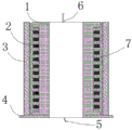
fig. 1 is a schematic view of a dry high-voltage coil according to an embodiment of the present invention.
Fig. 2 is a top view of a dry high voltage coil in an embodiment of the invention.
Fig. 3 and 4 are schematic diagrams of a high-voltage coil bobbin of a dry high-voltage coil in an embodiment of the invention.
Fig. 5 and 6 are schematic diagrams of a casting mold of the dry type high-voltage coil in the embodiment of the invention.
Reference numbers in the figures: 1-high-voltage coil framework, 2-insulated wire, 3-casting mould, 4-sampling plate, 5-wire inlet end, 6-wire outlet end and 7-epoxy resin.
Detailed Description
In order to make the objects, technical solutions and advantages of the present invention more apparent, the present invention is described in further detail below with reference to the accompanying drawings and embodiments. It should be understood that the specific embodiments described herein are merely illustrative of the invention and are not intended to limit the invention.
It will be understood that when an element is referred to as being "secured to" or "disposed on" another element, it can be directly on the other element or be indirectly on the other element. When an element is referred to as being "connected to" another element, it can be directly connected to the other element or be indirectly connected to the other element.
In the description of the present invention, it is to be understood that the terms "length", "width", "upper", "lower", "front", "rear", "left", "right", "vertical", "horizontal", "top", "bottom", "inner", "outer", and the like, indicate orientations or positional relationships based on the orientations or positional relationships illustrated in the drawings, and are used merely for convenience in describing the present invention and for simplicity in description, and do not indicate or imply that the devices or elements referred to must have a particular orientation, be constructed in a particular orientation, and be operated, and thus, are not to be construed as limiting the present invention.
Furthermore, the terms "first", "second" and "first" are used for descriptive purposes only and are not to be construed as indicating or implying relative importance or implicitly indicating the number of technical features indicated. Thus, a feature defined as "first" or "second" may explicitly or implicitly include one or more of that feature. In the description of the present invention, "a plurality" means two or more unless specifically defined otherwise.
For better understanding of the above technical solutions, the following detailed descriptions will be provided in conjunction with the drawings and the detailed description of the present invention.
Example (b):
referring to fig. 1-6, the present embodiment provides a dry type high voltage coil, including: a high-voltage coil bobbin 1;
the insulating wire 2 is wound on the outer surface of the high-voltage coil framework 1;
the epoxy resin 7 is wrapped on the outer surfaces of the insulated wire 2 and the high-voltage coil framework 1 and is solidified to form a rigid body;
the casting mold 3 is arranged on the outer surface of the epoxy resin 7;
one side of the sampling plate 4 is connected with the high-voltage coil framework 1 and the casting mold 3;
the high-voltage coil comprises a wire outlet end 6 and a wire inlet end 5, wherein the wire outlet end 6 and the wire inlet end 5 are respectively arranged at two ends of the high-voltage coil framework 1.
In the dry-type high-voltage coil provided by this embodiment, the insulating wires 2 are wound in segments and are respectively and independently wound on the high-voltage coil framework 1.
In the dry-type high-voltage coil provided by this embodiment, the insulation wire 2 wound in segments is divided into 12 segments, which totally include 2400 turns of insulation wire, 200 turns of each segment of insulation wire, and is wound by using a single conducting wire.
In the dry-type high-voltage coil provided by the embodiment, the DMD insulation paper is arranged at the transition part between each two segments.
In the dry-type high-voltage coil provided by the embodiment, each layer of the insulating wire 2 in each section has 20 turns and 10 layers, and each two layers are separated by the glass ribbon.
In the dry high-voltage coil provided by this embodiment, the lower end of the casting mold 3, the sampling plate 4 and the high-voltage coil framework 1 are bonded by 502 glue.
In the dry high-voltage coil provided by this embodiment, the sampling plate 4 is made of a PCB board, and a sampling coil with 10 turns is printed inside the sampling plate 4.
In the dry high-voltage coil provided by this embodiment, the sampling plate 4 is provided with a ground connection point, and the ground connection point is connected to the ground terminal of the insulating wire 2.
In the dry high-voltage coil provided by this embodiment, the epoxy resin 7 is a bisphenol a two-component epoxy resin with a heat resistance level of H, the A, B component has a mixed viscosity of less than 1000 pa, and the compressive strength of the cured epoxy resin is higher than 20 kv/mm by using a high-temperature curing process.
The first aspect has the following technical effects or advantages: by adopting the integral packaging design, the lead and the insulating material are solidified into a rigid body through the epoxy resin 7, and normal work under a high-voltage state can be realized without the help of a main insulating material of the transformer.
The high-voltage coil framework 1 is mainly used for supporting the winding of the insulated wire 2, the outer diameter of the high-voltage coil framework is the same as the effective inner diameter of the coil in size, the high-voltage coil framework 1 is a glass reinforced plastic framework, the glass reinforced plastic framework is formed by processing FR4 glass reinforced plastic profiles, and an internal cavity is used for mounting a transformer core.
The insulated wire 2 adopts a sectional winding scheme, 2400 turns of conducting wires are divided into 12 sections according to the design scheme, each section has 200 turns, a single conducting wire is adopted for winding, and DMD insulating paper is used for strengthening insulation at the transition part between the sections in the manufacturing process.
Each layer of lead in the section has 20 turns and 10 layers, and glass ribbons are used for separation between layers, so that the heat dissipation efficiency of the coil can be improved.
The lower end of the pouring mold 3 is adhered to the sampling plate 4 and the high-voltage coil framework 1 through 502 glue, and the function of the pouring mold is to provide a mold for epoxy resin pouring, wherein the pouring mold 3 is an epoxy cylinder which is made of glass steel materials, can be processed by section bars, and can also be manufactured by batch pouring of molds.
The sampling plate 4 is made of a PCB board, 10 turns of sampling coils are printed inside the sampling plate, and the sampling plate is used for measuring the real-time voltage of the high-voltage coil of the transformer.
The sampling plate 4 is provided with a grounding connection point which is connected with the grounding end of the insulated wire 2, and the grounding end is simultaneously used as the grounding end of the 10-turn sampling coil.
The inlet end 5 and the outlet end 6 are external interfaces of the high-voltage coil, and the coil is usually wound from the inlet end 5, and the winding direction accords with the right-hand rule with the magnetic flux direction of the transformer. The inter-layer size and the inter-segment size are monitored during the winding process, and the two sizes can influence the parasitic parameters of the transformer.
The epoxy resin 7 adopts bisphenol A bi-component epoxy resin with H-grade heat resistance, the A, B component has the mixed viscosity lower than 1000 Pas, and the high-temperature curing process is adopted, and the compressive strength of the cured epoxy resin is higher than 20 kilovolts/millimeter.
In a second aspect, a process for preparing the dry-type high-voltage coil comprises the following steps:
step 1: cleaning the high-voltage coil framework, drying and then entering a manufacturing link;
step 2: one end of an insulated wire is fixed on a high-voltage coil framework, and is wound according to the determined winding direction of the right-hand rule;
and step 3: after the winding is finished, putting the material into an oven for drying;
and 4, step 4: bonding the wound coil, the sampling plate and the casting mold together through 502 glue, and entering the next step after the bonding is firm;
and 5: mixing the two-component epoxy resin according to the process requirement, uniformly stirring, placing the mixture into a vacuum box, degassing, and injecting the mixture into a casting mold;
step 6: and (3) putting the workpiece into an oven, heating to 130 ℃, keeping for 3 hours, naturally cooling to room temperature, and finishing the manufacturing of the dry-type high-voltage coil.
The second aspect plays the same role as the first aspect, and therefore, the description thereof is omitted.
Finally, it should be noted that: although the present invention has been described in detail with reference to the foregoing embodiments, it will be apparent to those skilled in the art that changes may be made in the embodiments and/or equivalents thereof without departing from the spirit and scope of the invention. Any modification, equivalent replacement, or improvement made within the spirit and principle of the present invention should be included in the protection scope of the present invention.
Claims (10)
1. A dry high voltage coil, characterized by: the method comprises the following steps:
a high-voltage coil bobbin (1);
the insulating wire (2) is wound on the outer surface of the high-voltage coil framework (1);
the epoxy resin (7) is wrapped on the outer surfaces of the insulated wire (2) and the high-voltage coil framework (1) and is solidified to form a rigid body;
the casting mold (3), the casting mold (3) is arranged on the outer surface of the epoxy resin (7);
one side of the sampling plate (4) is connected with the high-voltage coil framework (1) and the casting mold (3);
the coil comprises a coil outlet end (6) and a coil inlet end (5), wherein the coil outlet end (6) and the coil inlet end (5) are respectively arranged at two ends of the high-voltage coil framework (1).
2. A dry high-voltage coil as claimed in claim 1, wherein: the insulating wire (2) is wound in sections and is respectively and independently wound on the high-voltage coil framework (1).
3. A dry high-voltage coil as claimed in claim 2, wherein: the insulated wire (2) wound in sections is divided into 12 sections, 2400 turns of insulated wire are included totally, 200 turns of insulated wire are included totally, and a single conducting wire is used for winding.
4. A dry high-voltage coil as claimed in claim 3, wherein: and DMD insulating paper is arranged at the transition part between every two sections.
5. A dry high-voltage coil according to claim 4, characterized in that: each layer of the insulated wires (2) in each section has 20 turns and has 10 layers, and each two layers are separated by a glass ribbon.
6. A dry high-voltage coil according to claim 5, characterized in that: the lower end of the pouring mold (3) is bonded with the sampling plate (4) and the high-voltage coil framework (1) through 502 glue.
7. A dry high-voltage coil according to claim 6, characterized in that: the sampling plate (4) is made of a PCB (printed circuit board), and a sampling coil with 10 turns is printed inside the sampling plate (4).
8. A dry high-voltage coil as claimed in claim 7, wherein: and a grounding connection point is arranged on the sampling plate (4), and the grounding connection point is connected with the grounding end of the insulated wire (2).
9. A dry high-voltage coil as claimed in claim 1, wherein: the epoxy resin (7) is bisphenol A bi-component epoxy resin with the heat resistance grade of H grade, the A, B component has the mixed viscosity of less than 1000 Pas, and the compressive strength of the cured epoxy resin is higher than 20 kilovolts/millimeter by adopting a high-temperature curing process.
10. A process for preparing a dry high-voltage coil according to any one of claims 1 to 9, characterized in that: the method comprises the following steps:
step 1: cleaning the high-voltage coil framework, drying and then entering a manufacturing link;
step 2: one end of an insulated wire is fixed on a high-voltage coil framework, and is wound according to the determined winding direction of the right-hand rule;
and step 3: after the winding is finished, putting the material into an oven for drying;
and 4, step 4: bonding the wound coil, the sampling plate and the casting mold together through 502 glue, and entering the next step after the bonding is firm;
and 5: mixing the two-component epoxy resin according to the process requirement, uniformly stirring, placing the mixture into a vacuum box, degassing, and injecting the mixture into a casting mold;
step 6: and (3) putting the workpiece into an oven, heating to 130 ℃, keeping for 3 hours, naturally cooling to room temperature, and finishing the manufacturing of the dry-type high-voltage coil.
Priority Applications (1)
| Application Number | Priority Date | Filing Date | Title |
|---|---|---|---|
| CN202011064999.8A CN112201460A (en) | 2020-09-30 | 2020-09-30 | Dry-type high-voltage coil and preparation process thereof |
Applications Claiming Priority (1)
| Application Number | Priority Date | Filing Date | Title |
|---|---|---|---|
| CN202011064999.8A CN112201460A (en) | 2020-09-30 | 2020-09-30 | Dry-type high-voltage coil and preparation process thereof |
Publications (1)
| Publication Number | Publication Date |
|---|---|
| CN112201460A true CN112201460A (en) | 2021-01-08 |
Family
ID=74013695
Family Applications (1)
| Application Number | Title | Priority Date | Filing Date |
|---|---|---|---|
| CN202011064999.8A Pending CN112201460A (en) | 2020-09-30 | 2020-09-30 | Dry-type high-voltage coil and preparation process thereof |
Country Status (1)
| Country | Link |
|---|---|
| CN (1) | CN112201460A (en) |
Cited By (1)
| Publication number | Priority date | Publication date | Assignee | Title |
|---|---|---|---|---|
| WO2023125633A1 (en) * | 2021-12-29 | 2023-07-06 | 江苏神马电力股份有限公司 | High-voltage winding and method for preparing high-voltage winding |
-
2020
- 2020-09-30 CN CN202011064999.8A patent/CN112201460A/en active Pending
Cited By (1)
| Publication number | Priority date | Publication date | Assignee | Title |
|---|---|---|---|---|
| WO2023125633A1 (en) * | 2021-12-29 | 2023-07-06 | 江苏神马电力股份有限公司 | High-voltage winding and method for preparing high-voltage winding |
Similar Documents
| Publication | Publication Date | Title |
|---|---|---|
| US9478347B2 (en) | Dry type transformer with improved cooling | |
| CN102013322B (en) | Dry-type high-voltage capacitor core and manufacturing method thereof | |
| CN102576596A (en) | Disc wound transformer with improved cooling | |
| CN202333669U (en) | Wall bushing used for switch cabinet | |
| CN104124043A (en) | Casting type split reactor | |
| CN112201460A (en) | Dry-type high-voltage coil and preparation process thereof | |
| CA1224548A (en) | Method of making an electrical transformer | |
| CN112271065A (en) | High-power high-voltage high-frequency transformer | |
| CN201845638U (en) | Broadband inductor | |
| CN1516206A (en) | Resin-poured insulation dry transformer and its production method | |
| CN201084525Y (en) | A bare-conductor dry-type transformer coil | |
| CN112562972B (en) | Surface-mounted transformer and processing method thereof | |
| EP4099348A2 (en) | Dry-type transformer and winding method thereof | |
| CN111768959A (en) | Transformer device | |
| US3548357A (en) | Encapsulated electrical inductive apparatus | |
| CN108492979B (en) | Pouring method for insulating cylinder between high-voltage windings of 10kV grounding transformer | |
| CN209880353U (en) | Iron core reactor structure | |
| CN110752080A (en) | Epoxy resin insulation high-frequency high-voltage transformer | |
| CN114220640A (en) | Low-voltage coil for dry-type transformer | |
| CN113451017A (en) | High-voltage winding structure of dry-type insulation high-voltage transformer | |
| CN201608024U (en) | High-frequency and high-voltage solid rectifier transformer | |
| CN116313439B (en) | Insulation pouring structure and pouring manufacturing method for high-voltage coil of transformer | |
| CN216287908U (en) | Glue-pouring high-voltage isolation transformer | |
| CN213519540U (en) | Wire outlet structure of dry type transformer | |
| CN2641784Y (en) | Dry type transformer of resin casted insulation winding iron core |
Legal Events
| Date | Code | Title | Description |
|---|---|---|---|
| PB01 | Publication | ||
| PB01 | Publication | ||
| WD01 | Invention patent application deemed withdrawn after publication | ||
| WD01 | Invention patent application deemed withdrawn after publication |
Application publication date: 20210108 |