CN112191050A - Dust collector is used in electric automatization workshop - Google Patents
Dust collector is used in electric automatization workshop Download PDFInfo
- Publication number
- CN112191050A CN112191050A CN202011412897.0A CN202011412897A CN112191050A CN 112191050 A CN112191050 A CN 112191050A CN 202011412897 A CN202011412897 A CN 202011412897A CN 112191050 A CN112191050 A CN 112191050A
- Authority
- CN
- China
- Prior art keywords
- auxiliary
- box
- dust removal
- pull rod
- dust
- Prior art date
- Legal status (The legal status is an assumption and is not a legal conclusion. Google has not performed a legal analysis and makes no representation as to the accuracy of the status listed.)
- Granted
Links
Images


Classifications
-
- B—PERFORMING OPERATIONS; TRANSPORTING
- B01—PHYSICAL OR CHEMICAL PROCESSES OR APPARATUS IN GENERAL
- B01D—SEPARATION
- B01D46/00—Filters or filtering processes specially modified for separating dispersed particles from gases or vapours
- B01D46/24—Particle separators, e.g. dust precipitators, using rigid hollow filter bodies
- B01D46/2403—Particle separators, e.g. dust precipitators, using rigid hollow filter bodies characterised by the physical shape or structure of the filtering element
- B01D46/2411—Filter cartridges
-
- B—PERFORMING OPERATIONS; TRANSPORTING
- B01—PHYSICAL OR CHEMICAL PROCESSES OR APPARATUS IN GENERAL
- B01D—SEPARATION
- B01D46/00—Filters or filtering processes specially modified for separating dispersed particles from gases or vapours
- B01D46/42—Auxiliary equipment or operation thereof
- B01D46/48—Removing dust other than cleaning filters, e.g. by using collecting trays
-
- B—PERFORMING OPERATIONS; TRANSPORTING
- B01—PHYSICAL OR CHEMICAL PROCESSES OR APPARATUS IN GENERAL
- B01D—SEPARATION
- B01D46/00—Filters or filtering processes specially modified for separating dispersed particles from gases or vapours
- B01D46/56—Filters or filtering processes specially modified for separating dispersed particles from gases or vapours with multiple filtering elements, characterised by their mutual disposition
-
- B—PERFORMING OPERATIONS; TRANSPORTING
- B01—PHYSICAL OR CHEMICAL PROCESSES OR APPARATUS IN GENERAL
- B01D—SEPARATION
- B01D46/00—Filters or filtering processes specially modified for separating dispersed particles from gases or vapours
- B01D46/66—Regeneration of the filtering material or filter elements inside the filter
- B01D46/74—Regeneration of the filtering material or filter elements inside the filter by forces created by movement of the filter element
- B01D46/76—Regeneration of the filtering material or filter elements inside the filter by forces created by movement of the filter element involving vibrations
Landscapes
- Chemical & Material Sciences (AREA)
- Chemical Kinetics & Catalysis (AREA)
- Physics & Mathematics (AREA)
- Geometry (AREA)
- Filtering Of Dispersed Particles In Gases (AREA)
Abstract
The invention relates to the field of electrical automation, in particular to a dust removal device for an electrical automation workshop.A support plate is fixedly arranged in a box body, two dust removal boxes are oppositely and fixedly arranged on the left side and the right side of the support plate, a main air inlet and an auxiliary air inlet are respectively arranged on the left side wall and the right side wall of the box body, a first plugging mechanism is arranged at the auxiliary air inlet, a second plugging mechanism is respectively arranged in a first air outlet pipe and a second air outlet pipe, an air guide pipe is connected between the first air outlet pipe and the second dust removal box, and a linkage mechanism for opening and closing the first plugging mechanism and the second plugging mechanism is arranged on the box body; when the dust content in a workshop is less, the dust is removed only through the first dust removal box; when the dust content requirement of a workshop is high, secondary dust removal is carried out through the second dust removal box after dust removal is carried out through the first dust removal box; or dust is removed through the first dust removal box and the second dust removal box simultaneously, so that the dust is removed quickly.
Description
Technical Field
The invention relates to the field of electrical automation, in particular to a dust removal device for an electrical automation workshop.
Background
Electrical equipment is by the wide application in fields such as industry, electron, electrical equipment often need long-time operation, can produce a large amount of heats in electrical equipment's operation process, causes equipment operation delay or trouble, for giving electrical equipment heat dissipation, often can set up more louvre on electrical equipment's storage box, but the louvre has often increased the entering of dust, consequently just need in real time to the dust in the electric automatization workshop handle the purification. Dust removal purification equipment in the existing market is diverse, also is different to the degree that the dust purified, and the dust removal purification equipment that nevertheless has now is single dust collecting equipment mostly and absorbs the dust, because the space in the electric automatization workshop is great, traditional dust collecting equipment is comprehensive high-efficient inadequately to the processing of dust. In addition, a large amount of dust can be accumulated in the dust removing equipment after the dust removing equipment runs for a long time, the dust removing equipment needs to be cleaned regularly to ensure the high efficiency of the equipment in dust treatment, and the traditional dust removing equipment is not convenient and fast to clean the dust in the traditional dust removing equipment.
Disclosure of Invention
The invention aims to solve the technical problem of providing a dust removal device for an electric automation workshop, which can provide a plurality of dust removal modes according to different requirements of the workshop, is convenient for cleaning internal dust and solves the problems in the prior art.
In order to solve the technical problems, the technical scheme of the invention is as follows: a supporting plate is fixedly installed in the box body, two dust removing boxes are oppositely and fixedly installed on the left side and the right side of the supporting plate, the two dust removing boxes are respectively a first dust removing box located on the left side and a second dust removing box located on the right side, two cleaning holes are oppositely formed in the left side and the right side of the supporting plate, the bottoms of the dust removing boxes are communicated with the corresponding cleaning holes, and a dust removing mechanism is arranged below the supporting plate; a main air inlet and an auxiliary air inlet are respectively formed in the left side wall and the right side wall of the box body, air inlet pipes are respectively connected between the main air inlet and the first dust removal box and between the auxiliary air inlet and the second dust removal box, and a first blocking mechanism is arranged at the auxiliary air inlet; the top parts of the first dust removal box and the second dust removal box are respectively and fixedly provided with a first air outlet pipe and a second air outlet pipe which extend vertically, the upper ends of the first air outlet pipe and the second air outlet pipe respectively extend to the outer side of the box body, a second plugging mechanism is respectively arranged in the first air outlet pipe and the second air outlet pipe, and an air guide pipe is connected between the first air outlet pipe and the second dust removal box; the box body is provided with a linkage mechanism for opening and closing the first blocking mechanism and the second blocking mechanism; and a dust removing mechanism is arranged in the dust removing box.
As a preferred technical scheme, the second plugging mechanism comprises a first adjusting pipe and a second adjusting pipe which are respectively slidably mounted in the first air outlet pipe and the second air outlet pipe, the upper ends of the first adjusting pipe and the second adjusting pipe are both closed ends, the outer sides of the first adjusting pipe and the second adjusting pipe are respectively provided with a plurality of air holes, annular plates are coaxially and fixedly mounted in the first air outlet pipe and the second air outlet pipe respectively, and first tension springs are respectively connected between the lower ends of the first adjusting pipe and the second adjusting pipe and the corresponding annular plates; the upper ends of the first adjusting pipe and the second adjusting pipe are respectively and fixedly provided with a first auxiliary block and a second auxiliary block, and the first auxiliary block and the second auxiliary block are both used for being connected with the linkage mechanism.
As an optimal technical scheme, the first plugging mechanism comprises an installation cavity located in the right side wall of the box body, a slot is arranged at the bottom of the installation cavity, the slot is communicated with the auxiliary air inlet, a baffle is slidably mounted in the slot from top to bottom, a second tension spring is connected between the lower end of the baffle and the bottom of the slot, a third auxiliary block located in the installation cavity is fixedly mounted at the upper end of the baffle, and the third auxiliary block is used for being connected with the linkage mechanism.
As a preferred technical scheme, the linkage mechanism comprises a driving box positioned above the box body, two vertical plates are oppositely and fixedly installed on the left and right sides of the top of the box body, and the driving box is fixedly installed between the upper ends of the two vertical plates; a first driving shaft extending transversely is rotatably mounted in the driving box, a first gear is coaxially and fixedly mounted on the first driving shaft, a first auxiliary cavity is arranged in the first auxiliary cavity, a first auxiliary hole extending upwards and penetrating through the first auxiliary cavity is formed in the top wall of the first auxiliary cavity, a first pull rod is movably mounted in the first auxiliary hole, a first pull block positioned in the first auxiliary cavity is fixedly mounted at the lower end of the first pull rod, the upper end of the first pull rod extends into the driving box, a first rack meshed with the first gear is fixedly mounted on the first pull rod, and a first motor used for driving the first driving shaft to rotate is fixedly mounted on the driving box; a second driving shaft which extends transversely is rotatably mounted in the driving box, a second gear is coaxially and fixedly mounted on the second driving shaft, a second auxiliary cavity is arranged in the second auxiliary block, a second auxiliary hole which extends upwards and penetrates through the second auxiliary block is formed in the top wall of the second auxiliary cavity, a second pull rod is movably mounted in the second auxiliary hole, a second pull block which is located in the second auxiliary cavity is fixedly mounted at the lower end of the second pull rod, the upper end of the second pull rod extends into the driving box, a second rack which is meshed with the second gear is fixedly mounted on the second pull rod, and a second motor which is used for driving the second driving shaft to rotate is fixedly mounted on the driving box; a third driving shaft which extends transversely is rotatably mounted in the driving box, a third gear is coaxially and fixedly mounted on the third driving shaft, a third auxiliary hole which extends upwards and penetrates through the first auxiliary block is formed in the top wall of the first auxiliary cavity, a third pull rod is movably mounted in the third auxiliary hole, a third pull block which is located in the first auxiliary cavity is fixedly mounted at the lower end of the third pull rod, the upper end of the third pull rod extends into the driving box, and a third rack which is meshed with the third gear is fixedly mounted on the third pull rod; a fourth gear is coaxially and fixedly installed on the third driving shaft, a fourth auxiliary hole which extends upwards and penetrates through the second auxiliary block is formed in the top wall of the second auxiliary cavity, a fourth pull rod is movably installed in the fourth auxiliary hole, a fourth pull block located in the second auxiliary cavity is fixedly installed at the lower end of the fourth pull rod, the upper end of the fourth pull rod extends into the driving box, and a fourth rack meshed with the fourth gear is fixedly installed on the fourth pull rod; a fifth gear is coaxially and fixedly installed on the third driving shaft, a third auxiliary cavity is formed in the third auxiliary block, a fifth auxiliary hole which extends upwards and penetrates through the third auxiliary block is formed in the top wall of the third auxiliary cavity, a fifth pull rod is movably installed in the fifth auxiliary hole, a fifth pull block which is located in the third auxiliary cavity is fixedly installed at the lower end of the fifth pull rod, the upper end of the fifth pull rod extends into the driving box, and a fifth rack which is meshed with the fifth gear is fixedly installed on the fifth pull rod; the third rack, the fourth rack and the fifth rack are located on the same side of the third driving shaft, and a third motor for driving the third driving shaft to rotate is fixedly installed on the driving box.
As a further improvement, air inlet filter screens are respectively and fixedly arranged in the main air inlet and the auxiliary air inlet; two air outlet filter screens are oppositely and fixedly arranged between the front part and the rear part of the vertical plate, and the height of the air outlet filter screens is equal to that of the vertical plates.
As a preferred technical scheme, the dust removing mechanism comprises a connecting pipe fixedly installed on the inner side of the top wall of the dust removing box, the upper end of the connecting pipe is communicated with the first air outlet pipe or the second air outlet pipe, an air filtering cylinder with an open upper end is movably installed in the connecting pipe up and down, and a spring is connected between the upper end of the air filtering cylinder and the top of the dust removing box; first air-out pipe with there is the dust removal motor through dead lever fixed mounting respectively in the second air-out pipe, the axis of rotation of dust removal motor with first air-out pipe or the axis syntropy that the second goes out the tuber pipe extends, fixed mounting has fan blade in the axis of rotation of dust removal motor.
As a preferred technical scheme, the ash removing mechanism comprises two supporting shafts which are arranged in the box body in a left-right relative rotation mode, the supporting shafts extend forwards and backwards, a conveying belt is connected between the two supporting shafts, and a conveying motor for driving any one of the supporting shafts to rotate is fixedly arranged on the box body; the conveyer belt will two the bottom in clearance hole is sealed, the surface of conveyer belt is equipped with a plurality of edges the ash chute that the width direction of conveyer belt extends, one side of the diapire of box is equipped with the pull groove, slidable mounting has and is located in the pull groove connect the silo below the tail end of conveyer belt, be equipped with the intercommunication in the box the inner chamber of box with the punishment in advance hole in pull groove.
As a further improvement, a cleaning motor is fixedly mounted on the box body, a rotating shaft of the cleaning motor extends along the length direction of the conveyor belt, a cleaning shaft located below the tail end of the conveyor belt is coaxially and fixedly mounted on the rotating shaft of the cleaning motor, and bristles are arranged on the outer side of the cleaning shaft.
As a further improvement, two auxiliary shafts extending in the same direction as the support shaft are respectively rotatably mounted in the two dust removal boxes, a plurality of arc-shaped push blocks are uniformly arranged on the auxiliary shafts below the gas filter cylinder at intervals around the axis, and a convex block is arranged at the bottom of the gas filter cylinder and corresponds to the position of the push block; two coaxial fixed mounting respectively is gone up to the auxiliary shaft has and is located the first band pulley in the outside of box, two be connected with first belt between the first band pulley, one of them coaxial fixed mounting has and is located on the back shaft the second band pulley in the outside of box, one of them coaxial fixed mounting still is located on the auxiliary shaft the third band pulley in the outside of box, the second band pulley with be connected with the second belt between the third band pulley.
As a further improvement, the bottom of the box body is provided with a movable wheel.
According to the technical scheme, the dust removal device for the electric automation workshop is characterized in that a supporting plate is fixedly installed in the box body, two dust removal boxes are oppositely and fixedly installed on the left side and the right side of the supporting plate, a dust removal mechanism is arranged below the supporting plate, a main air inlet and an auxiliary air inlet are respectively arranged on the left side wall and the right side wall of the box body, a first blocking mechanism is arranged at the position of the auxiliary air inlet, a first air outlet pipe and a second air outlet pipe which extend vertically are fixedly installed at the tops of the first dust removal box and the second dust removal box respectively, a second blocking mechanism is arranged in the first air outlet pipe and the second air outlet pipe respectively, an air guide pipe is connected between the first air outlet pipe and the second dust removal box, and a linkage mechanism for opening and closing the first blocking mechanism and the second blocking mechanism is arranged on the box body; when the dust content of a workshop is low, only the first dust removal box is used for removing dust, so that energy consumption is saved, when the dust content requirement of the workshop is high, secondary dust removal is carried out through the second dust removal box after dust removal is carried out through the first dust removal box, so that the dust content in the air is effectively reduced, or dust removal is carried out through the first dust removal box and the second dust removal box simultaneously, so that rapid dust removal is carried out, the modes are various, and various use requirements of the workshop can be met; the first motor drives the first driving shaft to rotate so as to adjust the opening and closing of the first air outlet pipe, the second motor drives the second driving shaft to rotate so as to adjust the opening and closing of the second air outlet pipe, or the third motor drives the third driving shaft to rotate so as to simultaneously adjust the opening and closing of the first air outlet pipe, the second air outlet pipe and the auxiliary air inlet, so that the air conditioner has the advantage of convenience in adjustment; according to the dust collecting device, dust is collected through the dust grooves in the conveying belt, and the dust is conveyed to the material receiving grooves in a unified mode through the conveying belt, so that the dust is conveniently and intensively treated; according to the invention, the sweeping motor drives the sweeping shaft to rotate so as to clean the conveying belt, so that dust can be prevented from being accumulated in the dust groove; the conveying belt of the dust remover rotates and simultaneously drives the auxiliary shaft to rotate, the auxiliary shaft drives the air filter cylinder to vibrate up and down through the push block, so that dust accumulated on the outer wall of the air filter cylinder is promoted to fall off, and the dust remover has the advantage of good dust cleaning effect.
Drawings
In order to more clearly illustrate the embodiments of the present invention or the technical solutions in the prior art, the drawings used in the description of the embodiments or the prior art will be briefly described below, and it is obvious that the drawings in the following description are only some embodiments of the present invention, and for those skilled in the art, other drawings can be obtained according to these drawings without creative efforts.
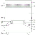
FIG. 1 is a schematic structural diagram of an embodiment of the present invention;
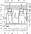
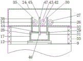
FIG. 2 is a schematic cross-sectional view of FIG. 1;
FIG. 3 is a schematic structural view of a first air outlet pipe according to an embodiment of the present invention;
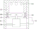
FIG. 4 is a schematic structural view of a first dust removal box according to an embodiment of the present invention;
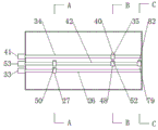
FIG. 5 is a schematic top view of a drive housing of an embodiment of the invention;
FIG. 6 is a schematic sectional view A-A of FIG. 5;
FIG. 7 is a schematic cross-sectional view B-B of FIG. 5;
fig. 8 is a schematic cross-sectional view of C-C in fig. 5.
In the figure: 1-a box body; 2-a support plate; 3-cleaning the hole; 4-a first dust removal box; 5-a second dust removal box; 6-main air inlet; 7-auxiliary air inlet; 8-an air inlet pipe; 9-a first air outlet pipe; 10-a second air outlet pipe; 11-a wind guide pipe; 12-a first conditioning tube; 13-a second regulating tube; 14-air holes; 15-an annular plate; 16-a first tension spring; 17-a first auxiliary block; 18-a second auxiliary block; 19-mounting a cavity; 20-a slot; 21-a baffle plate; 22-a second tension spring; 23-a third auxiliary block; 24-a drive box; 25-standing the plate; 26-a first drive shaft; 27-a first gear; 28-a first auxiliary chamber; 29-a first auxiliary hole; 30-a first pull rod; 31-a first pull block; 32-a first rack; 33-a first motor; 34-a second drive shaft; 35-a second gear; 36-a second auxiliary chamber; 37-a second auxiliary well; 38-a second tie rod; 39-a second pull block; 40-a second rack; 41-a second motor; 42-a third drive shaft; 43-third gear; 44-a third auxiliary well; 45-a third pull rod; 46-a third pull block; 47-third rack; 48-fourth gear; 49-fourth auxiliary hole; 50-a fourth pull rod; 51-a fourth pull block; 52-fourth rack; 53-a third motor; 54-intake screen; 55-air outlet filter screen; 56-connecting tube; 57-gas filter cylinder; 58-a spring; 59-a dust removal motor; 60-fan blades; 61-supporting shaft; 62-a conveyor belt; 63-a conveyor motor; 64-ash chute; 65-drawing the groove; 66-material receiving groove; 67-material passing holes; 68-a sweeping motor; 69-sweeping shaft; 70-an auxiliary shaft; 71-a push block; 72-a bump; 73-a first pulley; 74-a first belt; 75-a second pulley; 76-a third pulley; 77-a second belt; 78-moving wheels; 79-fifth gear; 80-a third auxiliary chamber; 81-fifth auxiliary hole; 82-a fifth pull rod; 83-a fifth pull block; 84-fifth rack.
Detailed Description
As shown in fig. 1 to 8, the dust removing device for the electric automation workshop comprises a box body 1, wherein a supporting plate 2 is fixedly installed in the box body 1, two dust removing boxes are oppositely and fixedly installed on the left side and the right side of the supporting plate 2, the two dust removing boxes are respectively a first dust removing box 4 on the left side and a second dust removing box 5 on the right side, two cleaning holes 3 are oppositely arranged on the left side and the right side of the supporting plate 2, the bottoms of the dust removing boxes are communicated with the corresponding cleaning holes 3, and a dust removing mechanism is arranged below the supporting plate 2; a main air inlet 6 and an auxiliary air inlet 7 are respectively arranged on the left side wall and the right side wall of the box body 1, air inlet pipes 8 are respectively connected between the main air inlet 6 and the first dust removal box 4 and between the auxiliary air inlet 7 and the second dust removal box 5, and a first plugging mechanism is arranged at the auxiliary air inlet 7; the top parts of the first dust removing box 4 and the second dust removing box 5 are respectively and fixedly provided with a first air outlet pipe 9 and a second air outlet pipe 10 which extend vertically, the upper ends of the first air outlet pipe 9 and the second air outlet pipe 10 respectively extend to the outer side of the box body 1, second blocking mechanisms are respectively arranged in the first air outlet pipe 9 and the second air outlet pipe 10, and an air guide pipe 11 is connected between the first air outlet pipe 9 and the second dust removing box 5; the box body 1 is provided with a linkage mechanism for opening and closing the first blocking mechanism and the second blocking mechanism; and a dust removing mechanism is arranged in the dust removing box.
The invention has three modes when in use:
in the first mode, the first air outlet pipe 9 is opened, the second air outlet pipe 10 is closed, the auxiliary air inlet 7 is closed simultaneously, dust-containing gas enters the first dust removal box 4 through the main air inlet 6, and after dust is removed through the dust removal mechanism in the first dust removal box 4, clean air flow is discharged through the first air outlet pipe 9, so that the mode is suitable for being used when the dust content in a workshop is less.
The second mode, open second air-out pipe 10, and close first air-out pipe 9, close supplementary air intake 7 simultaneously, dirty gas gets into first dust removal case 4 through main air intake 6 in, dust removal mechanism through first dust removal case 4 removes dust after, the air current through once removing dust gets into in second dust removal case 5 through first air-out pipe 9 and guide duct 11, and carry out the secondary dust removal back through the dust removal mechanism in the second dust removal case 5, clean air current is discharged through second air-out pipe 10, can effectively reduce the dust content in the air through the secondary removes dust, this mode is fit for using when higher to the dust content requirement in workshop.
And in the third mode, the first air outlet pipe 9 and the second air outlet pipe 10 are opened simultaneously, the auxiliary air inlet 7 is opened, dust-containing gas enters the first dust removal box 4 and the second dust removal box 5 through the main air inlet 6 and the auxiliary air inlet 7 respectively, dust removal is performed simultaneously by the dust removal mechanisms in the first dust removal box 4 and the second dust removal box 5, and after dust removal is finished, clean air flow is discharged through the first air outlet pipe 9 and the second air outlet pipe 10 respectively, so that the mode is suitable for rapidly removing dust in a workshop.
As shown in fig. 2 and 3, the second plugging mechanism includes a first adjusting pipe 12 and a second adjusting pipe 13 respectively slidably mounted in the first air outlet pipe 9 and the second air outlet pipe 10, the upper ends of the first adjusting pipe 12 and the second adjusting pipe 13 are both closed ends, the outer sides of the first adjusting pipe 12 and the second adjusting pipe 13 are respectively provided with a plurality of air holes 14, annular plates 15 are respectively coaxially and fixedly mounted in the first air outlet pipe 9 and the second air outlet pipe 10, and a first tension spring 16 is respectively connected between the lower ends of the first adjusting pipe 12 and the second adjusting pipe 13 and the corresponding annular plate 15; the upper ends of the first adjusting pipe 12 and the second adjusting pipe 13 are respectively and fixedly provided with a first auxiliary block 17 and a second auxiliary block 18, and the first auxiliary block 17 and the second auxiliary block 18 are both used for being connected with the linkage mechanism.
When the air-out device is used, the first auxiliary block 17 is pulled to move upwards through the linkage mechanism, the first auxiliary block 17 drives the first adjusting pipe 12 to move upwards to enable the air holes 14 to be exposed out of the first air-out pipe 9, at the moment, the first air-out pipe 9 is in an open state, and air in the first dust removal box 4 can be exhausted through the air holes 14; or the corresponding first tension spring 16 pulls the first adjusting pipe 12 to move downwards so that the air holes 14 are retracted into the first air outlet pipe 9, at the moment, the first air outlet pipe 9 is in a closed state, and the gas in the first dust removing box 4 cannot be discharged through the first air outlet pipe 9. Similarly, the second adjusting pipe 13 is driven by the linkage mechanism to move upwards to expose the air holes 14 out of the second air outlet pipe 10, and at this time, the second air outlet pipe 10 is in an open state; or the second adjusting pipe 13 is pulled by the corresponding first tension spring 16 to move downwards so that the air holes 14 are retracted into the second air outlet pipe 10, and at the moment, the second air outlet pipe 10 is in a closed state.
As shown in fig. 2 and 8, the first blocking mechanism includes an installation cavity 19 located in the right side wall of the box body 1, a slot 20 is arranged at the bottom of the installation cavity 19, the slot 20 is communicated with the auxiliary air inlet 7, a baffle 21 is vertically slidably installed in the slot 20, a second tension spring 22 is connected between the lower end of the baffle 21 and the bottom of the slot 20, a third auxiliary block 23 located in the installation cavity 19 is fixedly installed at the upper end of the baffle 21, and the third auxiliary block 23 is used for being connected with the linkage mechanism.
When the air conditioner is used, the third auxiliary block 23 is pulled to move upwards through the linkage mechanism, and the third auxiliary block 23 drives the baffle plate 21 to move upwards to open the auxiliary air inlet 7; or the second tension spring 22 pulls the baffle plate 21 to move downwards to close the auxiliary air inlet 7.
As shown in fig. 5 to 8, the linkage mechanism includes a driving box 24 located above the box body 1, two vertical plates 25 are relatively and fixedly installed on the left and right of the top of the box body 1, and the driving box 24 is fixedly installed between the upper ends of the two vertical plates 25; a first driving shaft 26 extending transversely is rotatably mounted in the driving box 24, a first gear 27 is coaxially and fixedly mounted on the first driving shaft 26, a first auxiliary cavity 28 is arranged in the first auxiliary block 17, a first auxiliary hole 29 extending upwards and penetrating through the first auxiliary block 17 is formed in the top wall of the first auxiliary cavity 28, a first pull rod 30 is movably mounted in the first auxiliary hole 29, a first pull block 31 located in the first auxiliary cavity 28 is fixedly mounted at the lower end of the first pull rod 30, the upper end of the first pull rod 30 extends into the driving box 24, a first rack 32 engaged with the first gear 27 is fixedly mounted on the first pull rod 30, and a first motor 33 for driving the first driving shaft 26 to rotate is fixedly mounted on the driving box 24; a second driving shaft 34 extending transversely is rotatably mounted in the driving box 24, a second gear 35 is coaxially and fixedly mounted on the second driving shaft 34, a second auxiliary cavity 36 is arranged in the second auxiliary block 18, a second auxiliary hole 37 extending upwards and penetrating through the second auxiliary block 18 is formed in the top wall of the second auxiliary cavity 36, a second pull rod 38 is movably mounted in the second auxiliary hole 37, a second pull block 39 located in the second auxiliary cavity 36 is fixedly mounted at the lower end of the second pull rod 38, the upper end of the second pull rod 38 extends into the driving box 24, a second rack 40 engaged with the second gear 35 is fixedly mounted on the second pull rod 38, and a second motor 41 for driving the second driving shaft 34 to rotate is fixedly mounted on the driving box 24; a third driving shaft 42 extending transversely is rotatably mounted in the driving box 24, a third gear 43 is coaxially and fixedly mounted on the third driving shaft 42, a third auxiliary hole 44 extending upwards and penetrating through the first auxiliary block 17 is formed in the top wall of the first auxiliary cavity 28, a third pull rod 45 is movably mounted in the third auxiliary hole 44, a third pull block 46 positioned in the first auxiliary cavity 28 is fixedly mounted at the lower end of the third pull rod 45, the upper end of the third pull rod 45 extends into the driving box 24, and a third rack 47 engaged with the third gear 43 is fixedly mounted on the third pull rod 45; a fourth gear 48 is further coaxially and fixedly mounted on the third driving shaft 42, a fourth auxiliary hole 49 extending upward and penetrating through the second auxiliary block 18 is formed in the top wall of the second auxiliary cavity 36, a fourth pull rod 50 is movably mounted in the fourth auxiliary hole 49, a fourth pull block 51 located in the second auxiliary cavity 36 is fixedly mounted at the lower end of the fourth pull rod 50, the upper end of the fourth pull rod 50 extends into the driving box 24, and a fourth rack 52 engaged with the fourth gear 48 is fixedly mounted on the fourth pull rod 50; a fifth gear 79 is further coaxially and fixedly mounted on the third driving shaft 42, a third auxiliary cavity 80 is arranged in the third auxiliary block 23, a fifth auxiliary hole 81 which extends upwards and penetrates through the third auxiliary block 23 is formed in the top wall of the third auxiliary cavity 80, a fifth pull rod 82 is movably mounted in the fifth auxiliary hole 81, a fifth pull block 83 which is located in the third auxiliary cavity 80 is fixedly mounted at the lower end of the fifth pull rod 82, the upper end of the fifth pull rod 82 extends into the driving box 24, and a fifth rack 84 which is meshed with the fifth gear 79 is fixedly mounted on the fifth pull rod 82; the third rack 47, the fourth rack 52 and the fifth rack 84 are located on the same side of the third driving shaft 42, and a third motor 53 for driving the third driving shaft 42 to rotate is fixedly mounted on the driving box 24.
The first motor 33 drives the first driving shaft 26 and the first gear 27 to rotate forward, the first gear 27 drives the first pull rod 30 to move upward through the first rack 32 when rotating forward, the first pull rod 30 drives the first auxiliary block 17 to move upward through the first pull block 31, and the first auxiliary block 17 drives the first adjusting pipe 12 to move upward to open the first air outlet pipe 9; or the first motor 33 drives the first driving shaft 26 and the first gear 27 to rotate reversely, when the first gear 27 rotates reversely, the first rack 32 drives the first pull rod 30 to move downwards, and the corresponding first tension spring 16 pulls the first adjusting pipe 12 to move downwards so as to close the first air outlet pipe 9.
The second motor 41 drives the second driving shaft 34 and the second gear 35 to rotate forward, the second gear 35 drives the second pull rod 38 to move upward through the second rack 40 when rotating forward, the second pull rod 38 drives the second auxiliary block 18 to move upward through the second pull block 39, and the second auxiliary block 18 drives the second adjusting pipe 13 to move upward to open the second air outlet pipe 10; or the second motor 41 drives the second driving shaft 34 and the second gear 35 to rotate reversely, when the second gear 35 rotates reversely, the second rack 40 drives the second pull rod 38 to move downwards, and the corresponding first tension spring 16 pulls the second adjusting pipe 13 to move downwards, so that the second air outlet pipe 10 is closed.
The third motor 53 drives the third driving shaft 42 to rotate forwards, the third driving shaft 42 drives the third gear 43, the fourth gear 48 and the fifth gear 79 to rotate forwards, the third gear 43 drives the third pull rod 45 to move upwards through the third rack 47 when rotating forwards, the third pull rod 45 drives the first auxiliary block 17 to move upwards through the third pull block 46, and the first auxiliary block 17 drives the first adjusting pipe 12 to move upwards to open the first air outlet pipe 9; meanwhile, the fourth gear 48 drives the fourth pull rod 50 to move upwards through the fourth rack 52, the fourth pull rod 50 drives the second auxiliary block 18 to move upwards through the fourth pull block 51, and the second auxiliary block 18 drives the second adjusting pipe 13 to move upwards to open the second air outlet pipe 10; meanwhile, the fifth gear 79 drives the fifth pull rod 82 to move upwards through the fifth rack 84, the fifth pull rod 82 drives the third auxiliary block 23 to move upwards through the fifth pull block 83, and the third auxiliary block 23 drives the baffle 21 to move upwards to open the auxiliary air inlet 7. Or the third motor 53 drives the third driving shaft 42 to rotate reversely, the third driving shaft 42 drives the third gear 43, the fourth gear 48 and the fifth gear 79 to rotate reversely, the third gear 43, the fourth gear 48 and the fifth gear 79 respectively drive the third pull rod 45 to move upwards, the fourth pull rod 50 and the fifth pull rod 82 to move downwards, so that the first air outlet pipe 9, the second air outlet pipe 10 and the auxiliary air inlet 7 are closed again.
As shown in fig. 1 and fig. 2, an air intake filter 54 is fixedly installed in each of the main air intake 6 and the auxiliary air intake 7, and the air intake filter 54 is used for blocking foreign matters from entering the main air intake 6 and the auxiliary air intake 7. Two relative fixed mounting has two filter screens 55 of giving vent to anger around between the riser 25, the filter screen 55 of giving vent to anger highly equal with the riser 25, filter screen 55 of giving vent to anger is used for blockking that the foreign matter gets into first tuber pipe 9 and second tuber pipe 10 of giving vent to anger.
As shown in fig. 2 and 4, the dust removing mechanism includes a connecting pipe 56 fixedly installed on the inner side of the top wall of the dust removing box, the upper end of the connecting pipe 56 is communicated with the first air outlet pipe 9 or the second air outlet pipe 10, an air filtering cylinder 57 with an open upper end is movably installed in the connecting pipe 56 up and down, and a spring 58 is connected between the upper end of the air filtering cylinder 57 and the top of the dust removing box; first play tuber pipe 9 with there is dust removal motor 59 through dead lever fixed mounting respectively in the second play tuber pipe 10, the axis of rotation of dust removal motor 59 with first play tuber pipe 9 or the axis syntropy of second play tuber pipe 10 extends, fixed mounting has fan blade 60 in the axis of rotation of dust removal motor 59.
When the first air outlet pipe 9 or the second air outlet pipe 10 is opened, the corresponding dust removal motor 59 is started and drives the fan blade 60 to rotate, the fan blade 60 generates a bottom-up airflow and promotes the dust-containing gas entering the dust removal box to permeate the filter cylinder 57 upwards and be discharged from the corresponding air outlet pipe. When the dust-containing gas passes through the filter cylinder 57, the filter cylinder 57 blocks dust in the dust-containing gas to achieve the purpose of dust removal.
As shown in fig. 2, the ash removing mechanism includes two supporting shafts 61 installed in the box body 1 in a left-right relative rotation manner, the supporting shafts 61 extend forward and backward, a conveyor belt 62 is connected between the two supporting shafts 61, and a conveying motor 63 for driving any one of the supporting shafts 61 to rotate is fixedly installed on the box body 1; the conveyer belt 62 will two the bottom of clearance hole 3 is sealed, the surface of conveyer belt 62 is equipped with a plurality of edges ash chute 64 that the width direction of conveyer belt 62 extends, one side of the diapire of box 1 is equipped with drawing groove 65, slidable mounting has in drawing groove 65 to be located the below of the tail end of conveyer belt 62 connects silo 66, be equipped with the intercommunication in the box 1 the inner chamber of box 1 with drawing groove 65's punishment in advance hole 67.
After the air filter cylinder 57 blocks dust in the dust-containing gas, the dust is accumulated on the outer wall of the air filter cylinder 57, and along with the continuous accumulation of the dust, the dust falls into the dust groove 64 of the conveyor belt 62 through the cleaning hole 3 downwards under the action of gravity. When the dust is cleaned, the conveying motor 63 is started to drive one of the supporting shafts 61 to rotate, the supporting shaft 61 drives the conveying belt 62 to rotate, the dust moves along with the dust groove 64 on the conveying belt 62, and when the dust is conveyed to the tail end of the conveying belt 62, the dust downwards falls into the material receiving groove 66 through the material passing hole 67 so as to be collected.
A cleaning motor 68 is fixedly installed on the box body 1, a rotating shaft of the cleaning motor 68 extends along the length direction of the conveyor belt 62, a cleaning shaft 69 positioned below the tail end of the conveyor belt 62 is coaxially and fixedly installed on the rotating shaft of the cleaning motor 68, and bristles are arranged on the outer side of the cleaning shaft 69.
The sweeping motor 68 drives the sweeping shaft 69 to rotate, and the sweeping shaft 69 sweeps dust in the dust groove 64 above the material passing hole 67 through the bristles to prevent the dust from accumulating in the dust groove 64.
As shown in fig. 1 and 2, an auxiliary shaft 70 extending in the same direction as the support shaft 61 is rotatably mounted in each of the two dust removing boxes, a plurality of arc-shaped push blocks 71 are uniformly arranged on the auxiliary shaft 70 below the filter cylinder 57 at intervals around the axis, and a convex block 72 is arranged at the bottom of the filter cylinder 57 and at the position corresponding to the position of the push block 71; the two auxiliary shafts 70 are respectively and coaxially and fixedly provided with a first belt wheel 73 positioned on the outer side of the box body 1, a first belt 74 is connected between the first belt wheels 73, one of the support shafts 61 is coaxially and fixedly provided with a second belt wheel 75 positioned on the outer side of the box body 1, one of the auxiliary shafts 70 is also coaxially and fixedly provided with a third belt wheel 76 positioned on the outer side of the box body 1, and a second belt 77 is connected between the second belt wheel 75 and the third belt wheel 76.
When the transmission motor 63 drives the supporting shaft 61 to rotate, the supporting shaft 61 drives the third belt wheel 76 and one of the auxiliary shafts 70 to rotate through the second belt wheel 75 and the second belt 77, the two auxiliary shafts 70 are linked with the first belt wheel 73 and the first belt 74, the auxiliary shaft 70 drives the push block 71 to rotate, when the auxiliary shaft 70 drives one of the push blocks 71 to rotate to be in contact with the bump 72, the filter cylinder 57 is pushed to move upwards and the spring 58 is compressed, and when the auxiliary shaft 70 drives the push block 71 to be separated from the bump 72, the spring 58 in a compressed state pushes the filter cylinder 57 to move downwards, so that the filter cylinder 57 vibrates upwards and downwards, and dust accumulated on the outer wall of the filter cylinder 57 is enabled to fall off.
The bottom of the box body 1 is provided with moving wheels 78 for facilitating the movement of the box body 1.
The foregoing shows and describes the general principles, essential features, and advantages of the invention. It will be understood by those skilled in the art that the present invention is not limited to the embodiments described above, which are described in the specification and illustrated only to illustrate the principle of the present invention, but that various changes and modifications may be made therein without departing from the spirit and scope of the present invention, which fall within the scope of the invention as claimed. The scope of the invention is defined by the appended claims and equivalents thereof.
Claims (10)
1. The utility model provides an electric for automation workshop dust collector which characterized in that: the dust removal box comprises a box body, wherein a supporting plate is fixedly arranged in the box body, two dust removal boxes are oppositely and fixedly arranged on the left side and the right side of the supporting plate, the two dust removal boxes are respectively a first dust removal box positioned on the left side and a second dust removal box positioned on the right side, two cleaning holes are oppositely arranged on the left side and the right side of the supporting plate, the bottoms of the dust removal boxes are communicated with the corresponding cleaning holes, and a dust removal mechanism is arranged below the supporting plate; a main air inlet and an auxiliary air inlet are respectively formed in the left side wall and the right side wall of the box body, air inlet pipes are respectively connected between the main air inlet and the first dust removal box and between the auxiliary air inlet and the second dust removal box, and a first blocking mechanism is arranged at the auxiliary air inlet; the top parts of the first dust removal box and the second dust removal box are respectively and fixedly provided with a first air outlet pipe and a second air outlet pipe which extend vertically, the upper ends of the first air outlet pipe and the second air outlet pipe respectively extend to the outer side of the box body, a second plugging mechanism is respectively arranged in the first air outlet pipe and the second air outlet pipe, and an air guide pipe is connected between the first air outlet pipe and the second dust removal box; the box body is provided with a linkage mechanism for opening and closing the first blocking mechanism and the second blocking mechanism; and a dust removing mechanism is arranged in the dust removing box.
2. The dust removing device for an electric automation plant as set forth in claim 1, characterized in that: the second plugging mechanism comprises a first adjusting pipe and a second adjusting pipe which are respectively installed in the first air outlet pipe and the second air outlet pipe in a sliding mode, the upper ends of the first adjusting pipe and the second adjusting pipe are both closed ends, a plurality of air holes are respectively formed in the outer sides of the first adjusting pipe and the second adjusting pipe, annular plates are coaxially and fixedly installed in the first air outlet pipe and the second air outlet pipe respectively, and first tension springs are connected between the lower ends of the first adjusting pipe and the second adjusting pipe and the corresponding annular plates respectively; the upper ends of the first adjusting pipe and the second adjusting pipe are respectively and fixedly provided with a first auxiliary block and a second auxiliary block, and the first auxiliary block and the second auxiliary block are both used for being connected with the linkage mechanism.
3. The dust removing device for an electric automation plant as set forth in claim 2, characterized in that: first shutoff mechanism is including being located the installation cavity in the right side wall of box, the bottom of installation cavity is equipped with the slot, the slot with supplementary air intake is linked together, slidable mounting has the baffle from top to bottom in the slot, the lower extreme of baffle with be connected with the second extension spring between the bottom of slot, the upper end fixed mounting of baffle has and is located the supplementary piece of third of installation cavity, the supplementary piece of third is used for connecting interlock mechanism.
4. The dust removing device for an electric automation plant as set forth in claim 3, characterized in that: the linkage mechanism comprises a driving box positioned above the box body, two vertical plates are oppositely and fixedly arranged on the left and right sides of the top of the box body, and the driving box is fixedly arranged between the upper ends of the two vertical plates; a first driving shaft extending transversely is rotatably mounted in the driving box, a first gear is coaxially and fixedly mounted on the first driving shaft, a first auxiliary cavity is arranged in the first auxiliary cavity, a first auxiliary hole extending upwards and penetrating through the first auxiliary cavity is formed in the top wall of the first auxiliary cavity, a first pull rod is movably mounted in the first auxiliary hole, a first pull block positioned in the first auxiliary cavity is fixedly mounted at the lower end of the first pull rod, the upper end of the first pull rod extends into the driving box, a first rack meshed with the first gear is fixedly mounted on the first pull rod, and a first motor used for driving the first driving shaft to rotate is fixedly mounted on the driving box; a second driving shaft which extends transversely is rotatably mounted in the driving box, a second gear is coaxially and fixedly mounted on the second driving shaft, a second auxiliary cavity is arranged in the second auxiliary block, a second auxiliary hole which extends upwards and penetrates through the second auxiliary block is formed in the top wall of the second auxiliary cavity, a second pull rod is movably mounted in the second auxiliary hole, a second pull block which is located in the second auxiliary cavity is fixedly mounted at the lower end of the second pull rod, the upper end of the second pull rod extends into the driving box, a second rack which is meshed with the second gear is fixedly mounted on the second pull rod, and a second motor which is used for driving the second driving shaft to rotate is fixedly mounted on the driving box; a third driving shaft which extends transversely is rotatably mounted in the driving box, a third gear is coaxially and fixedly mounted on the third driving shaft, a third auxiliary hole which extends upwards and penetrates through the first auxiliary block is formed in the top wall of the first auxiliary cavity, a third pull rod is movably mounted in the third auxiliary hole, a third pull block which is located in the first auxiliary cavity is fixedly mounted at the lower end of the third pull rod, the upper end of the third pull rod extends into the driving box, and a third rack which is meshed with the third gear is fixedly mounted on the third pull rod; a fourth gear is coaxially and fixedly installed on the third driving shaft, a fourth auxiliary hole which extends upwards and penetrates through the second auxiliary block is formed in the top wall of the second auxiliary cavity, a fourth pull rod is movably installed in the fourth auxiliary hole, a fourth pull block located in the second auxiliary cavity is fixedly installed at the lower end of the fourth pull rod, the upper end of the fourth pull rod extends into the driving box, and a fourth rack meshed with the fourth gear is fixedly installed on the fourth pull rod; a fifth gear is coaxially and fixedly installed on the third driving shaft, a third auxiliary cavity is formed in the third auxiliary block, a fifth auxiliary hole which extends upwards and penetrates through the third auxiliary block is formed in the top wall of the third auxiliary cavity, a fifth pull rod is movably installed in the fifth auxiliary hole, a fifth pull block which is located in the third auxiliary cavity is fixedly installed at the lower end of the fifth pull rod, the upper end of the fifth pull rod extends into the driving box, and a fifth rack which is meshed with the fifth gear is fixedly installed on the fifth pull rod; the third rack, the fourth rack and the fifth rack are located on the same side of the third driving shaft, and a third motor for driving the third driving shaft to rotate is fixedly installed on the driving box.
5. The dust removing device for an electric automation plant as set forth in claim 4, characterized in that: an air inlet filter screen is fixedly arranged in the main air inlet and the auxiliary air inlet respectively; two air outlet filter screens are oppositely and fixedly arranged between the front part and the rear part of the vertical plate, and the height of the air outlet filter screens is equal to that of the vertical plates.
6. The dust removing device for an electric automation plant as set forth in claim 1, characterized in that: the dust removal mechanism comprises a connecting pipe fixedly arranged on the inner side of the top wall of the dust removal box, the upper end of the connecting pipe is communicated with the first air outlet pipe or the second air outlet pipe, an air filtering cylinder with an open upper end is movably arranged in the connecting pipe up and down, and a spring is connected between the upper end of the air filtering cylinder and the top of the dust removal box; first air-out pipe with there is the dust removal motor through dead lever fixed mounting respectively in the second air-out pipe, the axis of rotation of dust removal motor with first air-out pipe or the axis syntropy that the second goes out the tuber pipe extends, fixed mounting has fan blade in the axis of rotation of dust removal motor.
7. The dust removing device for an electric automation plant as set forth in claim 6, characterized in that: the ash removing mechanism comprises two supporting shafts which are arranged in the box body in a left-right relative rotating mode, the supporting shafts extend forwards and backwards, a conveying belt is connected between the two supporting shafts, and a conveying motor for driving any one of the supporting shafts to rotate is fixedly arranged on the box body; the conveyer belt will two the bottom in clearance hole is sealed, the surface of conveyer belt is equipped with a plurality of edges the ash chute that the width direction of conveyer belt extends, one side of the diapire of box is equipped with the pull groove, slidable mounting has and is located in the pull groove connect the silo below the tail end of conveyer belt, be equipped with the intercommunication in the box the inner chamber of box with the punishment in advance hole in pull groove.
8. The dust removing device for an electric automation plant as set forth in claim 7, characterized in that: the cleaning machine is characterized in that a cleaning motor is fixedly mounted on the box body, a rotating shaft of the cleaning motor extends along the length direction of the conveyor belt, a cleaning shaft located below the tail end of the conveyor belt is coaxially and fixedly mounted on the rotating shaft of the cleaning motor, and bristles are arranged on the outer side of the cleaning shaft.
9. The dust removing device for an electric automation plant as set forth in claim 7, characterized in that: auxiliary shafts extending in the same direction as the supporting shafts are rotatably mounted in the two dust removal boxes respectively, a plurality of arc-shaped push blocks are arranged on the auxiliary shafts below the gas filter cylinders at uniform intervals around the axis, and convex blocks are arranged at the positions, corresponding to the push blocks, of the bottoms of the gas filter cylinders; two coaxial fixed mounting respectively is gone up to the auxiliary shaft has and is located the first band pulley in the outside of box, two be connected with first belt between the first band pulley, one of them coaxial fixed mounting has and is located on the back shaft the second band pulley in the outside of box, one of them coaxial fixed mounting still is located on the auxiliary shaft the third band pulley in the outside of box, the second band pulley with be connected with the second belt between the third band pulley.
10. The dust removing device for an electric automation plant as set forth in claim 1, characterized in that: the bottom of the box body is provided with a movable wheel.
Priority Applications (1)
| Application Number | Priority Date | Filing Date | Title |
|---|---|---|---|
| CN202011412897.0A CN112191050B (en) | 2020-12-07 | 2020-12-07 | Dust collector is used in electric automatization workshop |
Applications Claiming Priority (1)
| Application Number | Priority Date | Filing Date | Title |
|---|---|---|---|
| CN202011412897.0A CN112191050B (en) | 2020-12-07 | 2020-12-07 | Dust collector is used in electric automatization workshop |
Publications (2)
| Publication Number | Publication Date |
|---|---|
| CN112191050A true CN112191050A (en) | 2021-01-08 |
| CN112191050B CN112191050B (en) | 2021-02-19 |
Family
ID=74034511
Family Applications (1)
| Application Number | Title | Priority Date | Filing Date |
|---|---|---|---|
| CN202011412897.0A Active CN112191050B (en) | 2020-12-07 | 2020-12-07 | Dust collector is used in electric automatization workshop |
Country Status (1)
| Country | Link |
|---|---|
| CN (1) | CN112191050B (en) |
Citations (7)
| Publication number | Priority date | Publication date | Assignee | Title |
|---|---|---|---|---|
| US5387406A (en) * | 1990-09-17 | 1995-02-07 | Walther & Cie Ag | Method and device for the adsorption and chemisorption, respectively, of gaseous components in a gas stream |
| JP2002320811A (en) * | 2001-04-27 | 2002-11-05 | Amano Corp | Dust level detection method for duct collector and apparatus therefor |
| CN103673643A (en) * | 2013-11-22 | 2014-03-26 | 宝钢集团广东韶关钢铁有限公司 | High-temperature flue gas waste heat recovery and dust extraction all-in-one device |
| CN108744803A (en) * | 2018-06-27 | 2018-11-06 | 逯亚静 | A kind of double mode deduster |
| CN209362069U (en) * | 2018-11-27 | 2019-09-10 | 温州市三合环保设备有限公司 | A kind of antifouling type industrial waste gas dedusting equipment |
| CN111408442A (en) * | 2020-04-21 | 2020-07-14 | 绍兴上虞丙方环保设备有限公司 | But broken sorter of building rubbish of dust fall |
| CN211885828U (en) * | 2019-12-26 | 2020-11-10 | 盐城市普天涂装工业有限公司 | Filter bag type dust collector capable of switching secondary filtration |
-
2020
- 2020-12-07 CN CN202011412897.0A patent/CN112191050B/en active Active
Patent Citations (7)
| Publication number | Priority date | Publication date | Assignee | Title |
|---|---|---|---|---|
| US5387406A (en) * | 1990-09-17 | 1995-02-07 | Walther & Cie Ag | Method and device for the adsorption and chemisorption, respectively, of gaseous components in a gas stream |
| JP2002320811A (en) * | 2001-04-27 | 2002-11-05 | Amano Corp | Dust level detection method for duct collector and apparatus therefor |
| CN103673643A (en) * | 2013-11-22 | 2014-03-26 | 宝钢集团广东韶关钢铁有限公司 | High-temperature flue gas waste heat recovery and dust extraction all-in-one device |
| CN108744803A (en) * | 2018-06-27 | 2018-11-06 | 逯亚静 | A kind of double mode deduster |
| CN209362069U (en) * | 2018-11-27 | 2019-09-10 | 温州市三合环保设备有限公司 | A kind of antifouling type industrial waste gas dedusting equipment |
| CN211885828U (en) * | 2019-12-26 | 2020-11-10 | 盐城市普天涂装工业有限公司 | Filter bag type dust collector capable of switching secondary filtration |
| CN111408442A (en) * | 2020-04-21 | 2020-07-14 | 绍兴上虞丙方环保设备有限公司 | But broken sorter of building rubbish of dust fall |
Also Published As
| Publication number | Publication date |
|---|---|
| CN112191050B (en) | 2021-02-19 |
Similar Documents
| Publication | Publication Date | Title |
|---|---|---|
| CN112191050B (en) | Dust collector is used in electric automatization workshop | |
| CN111248817A (en) | Hand-push type cleaning vehicle device for property cleaning | |
| CN114849430A (en) | Adsorption type drying machine convenient to clean and using method thereof | |
| CN210522044U (en) | Sack cleaner between trucd mixer | |
| CN112605058A (en) | Dust collector is used in processing of useless sand | |
| CN218872833U (en) | Vibrations formula polyamide resin granule sieve separator | |
| CN212263950U (en) | Cleaning device for jig | |
| CN210529593U (en) | Nursery stock fallen leaves collection device convenient to use | |
| CN113565501A (en) | Dust removal device for mining of mining equipment and application method thereof | |
| CN112547604A (en) | Dust collecting equipment for electronic product recovery | |
| CN219253391U (en) | Sealing gasket stamping forming device | |
| CN221625234U (en) | Dust collecting device of bagged cement truck loader | |
| CN220860945U (en) | Dust collector of efficient granulator | |
| CN113995347B (en) | Riding type full-automatic sweeper | |
| CN220083095U (en) | Efficient flow guiding device for flue | |
| CN213437188U (en) | Reducing mechanism is used in metal powder processing | |
| CN215034730U (en) | Rotary welding machine for electrical engineering | |
| CN216460012U (en) | Pig is dust collector for feed processing production | |
| CN220310952U (en) | Cereal edulcoration machine | |
| CN211140880U (en) | Environment-friendly grain scraping machine | |
| CN220779492U (en) | Dust collector of iron ore dry separation machine | |
| CN217119768U (en) | A dust collector for industrial automation | |
| CN221313861U (en) | Derusting scale sand blasting collecting device of vehicle-mounted heat exchanger | |
| CN215842219U (en) | Dry-wet separation device for dust fall | |
| CN221492618U (en) | Metal powder scattering device |
Legal Events
| Date | Code | Title | Description |
|---|---|---|---|
| PB01 | Publication | ||
| PB01 | Publication | ||
| SE01 | Entry into force of request for substantive examination | ||
| SE01 | Entry into force of request for substantive examination | ||
| GR01 | Patent grant | ||
| GR01 | Patent grant |