CN112186771A - Electric energy router based on matrix converter and electric energy routing method - Google Patents
Electric energy router based on matrix converter and electric energy routing method Download PDFInfo
- Publication number
- CN112186771A CN112186771A CN202011073332.4A CN202011073332A CN112186771A CN 112186771 A CN112186771 A CN 112186771A CN 202011073332 A CN202011073332 A CN 202011073332A CN 112186771 A CN112186771 A CN 112186771A
- Authority
- CN
- China
- Prior art keywords
- matrix converter
- phase
- interface
- switch state
- electric energy
- Prior art date
- Legal status (The legal status is an assumption and is not a legal conclusion. Google has not performed a legal analysis and makes no representation as to the accuracy of the status listed.)
- Granted
Links
Images


Classifications
-
- H—ELECTRICITY
- H02—GENERATION; CONVERSION OR DISTRIBUTION OF ELECTRIC POWER
- H02J—CIRCUIT ARRANGEMENTS OR SYSTEMS FOR SUPPLYING OR DISTRIBUTING ELECTRIC POWER; SYSTEMS FOR STORING ELECTRIC ENERGY
- H02J3/00—Circuit arrangements for ac mains or ac distribution networks
- H02J3/02—Circuit arrangements for ac mains or ac distribution networks using a single network for simultaneous distribution of power at different frequencies; using a single network for simultaneous distribution of ac power and of dc power
Landscapes
- Engineering & Computer Science (AREA)
- Power Engineering (AREA)
- Ac-Ac Conversion (AREA)
Abstract
The embodiment of the invention discloses an electric energy router based on a matrix converter and an electric energy routing method, wherein the electric energy router is constructed by a multi-port plug-and-play electric energy router based on three-phase and single-phase matrix converter type intelligent transformers, and the three-phase matrix converter type intelligent transformers can be connected with three-phase alternating current power grids or loads with different voltage grades; the single-phase matrix converter type intelligent transformer can output single-phase alternating current and direct current, and can be butted with a single-phase alternating current and direct current distributed power supply, energy storage equipment or a load by the characteristic of bidirectional power flow, and the unified converter structure simplifies a system circuit and control design; the matrix converter enables all interfaces of the electric energy router to be full single-stage power conversion without a large-capacity bus capacitor, so that the size of the electric energy router is reduced, and the efficiency and the reliability are improved; the high-frequency isolation transformer forms a high-frequency alternating current bus of the electric energy router, and parameters and the size of passive devices can be further reduced.
Description
Technical Field
The embodiment of the invention relates to the technical field of power electronic equipment of a power system, in particular to an electric energy router and an electric energy routing method based on a matrix converter.
Background
The electric energy router is used as one of key equipment for constructing an energy Internet, can be used for interconnecting transmission networks and power distribution networks with different voltage grades, has a basic voltage conversion function, provides a plug-and-play interface for the power networks, distributed power supplies, energy storage equipment and loads, and has the functions of electric isolation, electric energy quality control, energy bidirectional flow and the like. Renewable energy power generation is not suitable for a spontaneous self-service power supply system due to intermittent and fluctuating characteristics, and can be merged into an energy internet through an electric energy router to realize consumption and efficient utilization.
The power electronic converter is the basis of a power structure of an electric energy router, the electric energy router comprises a plurality of distributed power supplies, energy storage ports and load ports, and voltage grades among the ports are greatly different, such as a 10kV medium-voltage power grid alternating-current port, a 380V three-phase alternating-current port, a 220V single-phase alternating-current port, a 400V direct-current port and the like. In order to ensure the safety of equipment and the personal safety of operators, electrical isolation is generally required between ports with different voltage levels. The high-frequency intelligent transformer with high working frequency, small volume, light weight and flexible control becomes a key part.
Research has been conducted at home and abroad on various electric energy router topologies, such as a three-stage electric energy router topology based on a cascaded H-bridge, a three-level midpoint clamp, and a modular multilevel converter for high-voltage side rectification, i.e., Low Voltage Direct Current (LVDC) -High Frequency Alternating Current (HFAC) -High Voltage Direct Current (HVDC). The American FREEDOM center develops a 20kVA prototype of a high-voltage direct-current bus 7.2kV, a low-voltage side 240V/120V single-phase alternating current and a 400V direct current based on a cascade H bridge structure; the Zhang Richardship university designs a 1MVA topology with a medium-voltage distribution network at a high-voltage side and a 400V three-phase alternating-current bus at a low-voltage side based on a three-level neutral point clamped converter; a1 MW prototype of a 10kV high-voltage direct-current bus, a 380V low-voltage alternating-current bus and a 750V low-voltage direct-current bus is developed by a Chinese academy of sciences team based on a modular multilevel converter.
At present, an electric energy router based on three-level power conversion with high-voltage side rectification based on a cascade H bridge, three-level midpoint clamping and a modular multilevel converter is convenient for butt joint with various distributed new energy sources because of a low-voltage direct-current bus, however, due to the existence of the direct-current bus, electrolytic capacitors are needed on the high-voltage direct-current bus and the low-voltage direct-current bus, particularly, the high-voltage direct-current bus needs a large-capacity electrolytic capacitor bank for energy storage, the large-size direct-current bus capacitor which is easy to break down not only causes the volume of equipment to be greatly increased, but also shortens the service life of the system and reduces the reliability. In addition, a high-voltage bus is formed by a cascade H bridge and a cascade structure of the modular multilevel converter, so that the number of system power devices is greatly increased, and the cost is further increased.
Disclosure of Invention
Therefore, the embodiment of the invention provides an electric energy router based on a matrix converter and an electric energy routing method, and aims to solve the technical problems that the existing three-level electric energy router based on a cascaded H bridge, three-level neutral point clamping and modular multilevel converter for high-voltage side rectification is large in equipment size, multiple in system power devices and the like.
In order to achieve the above object, the embodiments of the present invention provide the following technical solutions:
according to a first aspect of embodiments of the present invention, there is provided a matrix converter based power router, comprising: a high frequency ac bus and at least two plug interfaces connected to said high frequency ac bus, said plug interfaces comprising: the high-frequency alternating-current bus comprises at least one input interface and at least one output interface, wherein the input interface inputs electric energy to the high-frequency alternating-current bus, and the input interface outputs the electric energy from the high-frequency alternating-current bus; the output interface includes: at least one first matrix converter interface formed by a single-stage single-phase matrix converter and/or at least one second matrix converter interface formed by a single-stage three-phase matrix converter; each plug interface is connected to the high-frequency alternating current bus through a high-frequency isolation transformer with the transformation ratio of 1: n.
Further, the first matrix converter interface comprises: at least one dc port for interfacing with a dc power source or load and at least one single phase ac cross-current port for interfacing with a single phase ac power grid or load.
Further, the second matrix converter interface comprises at least one first three-phase ac port for interfacing to a three-phase ac medium voltage grid, at least one second three-phase ac port for interfacing to a three-phase ac low voltage grid, and at least one third three-phase ac port for interfacing to a three-phase ac low voltage load.
Further, the power router further includes: the space vector modulator is respectively connected to each single-stage single-phase matrix converter and each single-stage three-phase matrix converter; the space vector modulator generates an indirect switching state S 'for each matrix converter according to a space vector modulation strategy of the indirect matrix converter, and the indirect switching state S' and a unit switching state SunitCombining to obtain an electric energy route switch state S; and at the beginning of the next control period, the electric energy routing switch state S is distributed to the corresponding matrix converter by the space vector modulator for switch control.
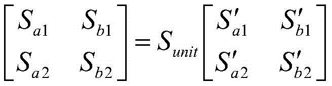
Preferably, the space vector modulator generates the power routing switch state S (a, b) of each single-stage single-phase matrix converter according to the following first switch state algorithm formula:

wherein the content of the first and second substances, is a single-stage single-phase matrix transformationThe electrical energy routing switch state of the device S (a, b);
 a first indirect switching state S' (a, b); sunitIs in unit switch state, when the first matrix converter interface is used as output interface, SunitTake the first unit switch state Sunit1,
 When the first matrix converter interface is used as the input interface, SunitTake the second unit switch state Sunit2,
The space vector modulator generates an electric energy routing switch state S (u, v, w) of each single-stage three-phase matrix converter according to the following second switch state algorithm formula:

wherein the content of the first and second substances,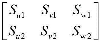 a switch state S (u, v, w) for the power routing of the single-stage three-phase matrix converter;
 a second indirect switch state S' (u, v, w); sunitIs in a unit switch state, when the second matrix converter interface is used as an output interface, SunitTake the first unit switch state Sunit1,
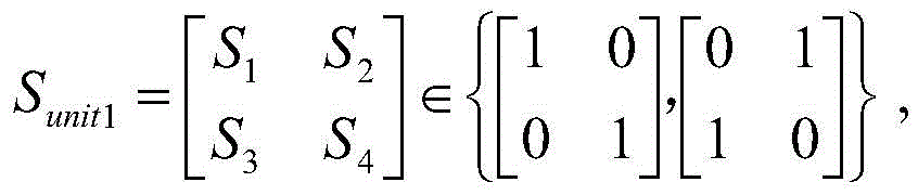 When the second matrix converter interface is used as the input interface, SunitTake the second unit switch state Sunit2,
Furthermore, the transformation ratio 1: n of the high-frequency isolation transformer is the average direct current voltage of each single-stage single-phase matrix converter/single-stage three-phase matrix converter Voltage amplitude of high frequency AC bus
 The ratio of (a) to (b).
According to a second aspect of embodiments of the present invention, there is provided a matrix converter based power routing method, the method comprising: connect two at least plug interfaces through a high frequency interchange generating line, plug interface includes: the high-frequency alternating-current bus comprises at least one input interface and at least one output interface, wherein the input interface inputs electric energy to the high-frequency alternating-current bus, and the input interface outputs the electric energy from the high-frequency alternating-current bus; the output interface includes: at least one first matrix converter interface formed by a single-stage single-phase matrix converter and/or at least one second matrix converter interface formed by a single-stage three-phase matrix converter; a three-phase alternating current port is used as a second matrix converter interface to be butted with a three-phase alternating current medium voltage power grid; or a three-phase alternating current port is used as a second matrix converter interface and is used for butting a three-phase alternating current low-voltage power grid; the three-phase alternating current low-voltage load is butted by taking at least one three-phase alternating current port as a second matrix converter interface; connecting a direct current power supply or a load by using at least one direct current port as a first matrix converter interface; and docking a single-phase alternating current grid or load through at least one single-phase current-intersecting port as a first matrix converter interface; each first matrix converter interface and each second matrix converter interface are connected to the high-frequency alternating current bus through a high-frequency isolation transformer with the transformation ratio of 1: n.
Further, the method further comprises: for each momentThe matrix converter generates an indirect switch state S' by using a space vector modulation strategy of the indirect matrix converter; the indirect switching state S' is compared with the unit switching state SunitCombining to obtain the electric energy routing switch state S of each matrix converter; and at the beginning of the next control period, distributing the electric energy routing switch state S to the corresponding matrix converter for switching control.
Further, the space vector modulator generates an electric energy routing switch state S (a, b) of each single-stage single-phase matrix converter according to the following first switch state algorithm formula:

wherein the content of the first and second substances, an electrical energy routing switch state S (a, b) for a single-stage single-phase matrix converter;
 a first indirect switching state S' (a, b); sunitIs in unit switch state, when the first matrix converter interface is used as output interface, SunitTake the first unit switch state Sunit1,
 When the first matrix converter interface is used as the input interface, SunitTake the second unit switch state Sunit2,
The space vector modulator generates an electric energy routing switch state S (u, v, w) of each single-stage three-phase matrix converter according to the following second switch state algorithm formula:

wherein the content of the first and second substances, a switch state S (u, v, w) for the power routing of the single-stage three-phase matrix converter;
 a second indirect switch state S' (u, v, w); sunitIs in a unit switch state, when the second matrix converter interface is used as an output interface, SunitTake the first unit switch state Sunit1,
 When the second matrix converter interface is used as the input interface, SunitTake the second unit switch state Sunit2,
Furthermore, the transformation ratio 1: n of the high-frequency isolation transformer is the average direct current voltage of each single-stage single-phase matrix converter/single-stage three-phase matrix converter Voltage amplitude of high frequency AC bus
 The ratio of (a) to (b).
The embodiment of the invention has the following advantages: the embodiment of the invention provides an electric energy router based on a matrix converter and an electric energy routing method, wherein the electric energy router is constructed on the basis of three-phase and single-phase matrix converter type intelligent transformers, and the three-phase matrix converter type intelligent transformers can be connected with three-phase alternating current power grids or loads with different voltage grades; the single-phase matrix converter type intelligent transformer can output single-phase alternating current and direct current, and can be butted with a single-phase alternating current and direct current distributed power supply, energy storage equipment or a load by the characteristic of bidirectional power flow, and the unified converter structure simplifies a system circuit and control design; the matrix converter enables all interfaces of the electric energy router to be full single-stage power conversion without a large-capacity bus capacitor, so that the size of the electric energy router is reduced, and the efficiency and the reliability are improved; the high-frequency isolation transformer forms a high-frequency alternating current bus of the electric energy router, so that parameters and the volume of passive devices can be further reduced; with the development of a novel wide-bandgap high-voltage silicon carbide semiconductor device technology, the three-phase matrix converter can be directly connected with a medium-voltage power grid without a cascade structure to expand the voltage level, and the switching devices and the cost are effectively reduced. Therefore, the embodiment of the invention realizes the matrix converter type intelligent transformer-based electric energy router, the full single-stage power conversion electronic interface with uniform structure and the high-frequency isolation alternating current bus, so that the matrix converter type intelligent transformer electric energy router has the advantages of compact volume, long service life, easiness in installation and maintenance, improved efficiency and reliability and greatly reduced volume.
Drawings
In order to more clearly illustrate the embodiments of the present invention or the technical solutions in the prior art, the drawings used in the description of the embodiments or the prior art will be briefly described below. It should be apparent that the drawings in the following description are merely exemplary, and that other embodiments can be derived from the drawings provided by those of ordinary skill in the art without inventive effort.
The structures, ratios, sizes, and the like shown in the present specification are only used for matching with the contents disclosed in the specification, so as to be understood and read by those skilled in the art, and are not used to limit the conditions that the present invention can be implemented, so that the present invention has no technical significance, and any structural modifications, changes in the ratio relationship, or adjustments of the sizes, without affecting the effects and the achievable by the present invention, should still fall within the range that the technical contents disclosed in the present invention can cover.
Fig. 1 is a schematic electrical structural diagram of an electrical energy router based on a matrix converter according to an embodiment of the present invention;
fig. 2 is a circuit diagram of a first matrix converter interface formed by a single-stage single-phase matrix converter according to an embodiment of the present invention;
FIG. 3 is a circuit diagram of a second matrix converter interface formed by a single-stage three-phase matrix converter according to an embodiment of the present invention;
fig. 4 is a voltage space vector diagram of a space vector modulation strategy of an indirect matrix converter of the single-stage single-phase matrix converter disclosed in the embodiment of the invention;
FIG. 5 is a schematic current space vector diagram of a space vector modulation strategy of an indirect matrix converter of the single-stage three-phase matrix converter disclosed in the present invention;
fig. 6 is a schematic power structure diagram of a plc software simulation example of a matrix converter-based power router according to another embodiment of the present invention;
FIG. 7 is a waveform diagram of 10kHz/400V high-frequency AC bus bar obtained from the simulation result of the simulation example shown in FIG. 6;
fig. 8a and 8b are graphs showing voltage and current waveforms of a 380V/50Hz three-phase ac power supply port, respectively, according to the simulation results of the simulation example shown in fig. 6;
FIGS. 9a and 9b are graphs of voltage and current waveforms, respectively, at a 120V/60Hz single-phase AC load port, as a result of a simulation of the example of the simulation shown in FIG. 6;
FIGS. 10a and 10b are graphs of voltage and current waveforms, respectively, at a 400V DC load port, obtained as a result of a simulation of the example simulation shown in FIG. 6;
fig. 11a and 11b are graphs of voltage and current waveforms of a 380V/50Hz three-phase ac load port, respectively, obtained as a result of the simulation example shown in fig. 6.
Detailed Description
The following description of the embodiments of the present invention is provided for illustrative purposes, and other advantages and effects of the present invention will become apparent to those skilled in the art from the present disclosure.
In the following description, for purposes of explanation and not limitation, specific details are set forth such as particular system structures, interfaces, techniques, etc. in order to provide a thorough understanding of the present invention. It will be apparent, however, to one skilled in the art that the present invention may be practiced in other embodiments that depart from these specific details. In other instances, detailed descriptions of well-known systems, circuits, and methods are omitted so as not to obscure the description of the present invention with unnecessary detail.
Referring to fig. 1, an embodiment of the present invention provides a matrix converter-based power router, which includes: a high frequency alternating current bus 01 and at least two plug interfaces connected to the high frequency alternating current bus 01, the plug interfaces comprising: the high-frequency alternating-current bus 01 comprises at least one input interface for inputting electric energy to the high-frequency alternating-current bus 01 and at least one output interface for outputting the electric energy from the high-frequency alternating-current bus 01, wherein the input interface is a first matrix converter interface formed by a single-stage single-phase matrix converter 02 and/or a second matrix converter interface formed by a single-stage three-phase matrix converter 03; the output interface includes: at least one first matrix converter interface formed by a single-stage single-phase matrix converter 02 and/or at least one second matrix converter interface formed by a single-stage three-phase matrix converter 03; the frequency of the high-frequency alternating current bus 01 depends on a switching device and can be 10 kHz-50 kHz.
Referring to fig. 1, further, the first matrix converter interface includes: at least one dc port and at least one single-phase ac port, wherein the dc port is used to interface a dc power source or load, such as the photovoltaic panel 05, the dc load 06 and the energy storage battery 07 shown in fig. 1; the single phase ac port is used to interface to a single phase ac grid or load, such as the 50/60Hz single phase ac load shown in fig. 1. The second matrix converter interface includes: at least one first three-phase ac port, at least one second three-phase ac port, and at least one third three-phase ac port; wherein the first three-phase ac port is used for docking a three-phase ac medium voltage grid, such as the 10kV three-phase ac medium voltage grid shown in fig. 1, the second three-phase ac port is used for docking a three-phase ac low voltage grid, such as the 380V three-phase ac low voltage grid shown in fig. 1, and the third three-phase ac port is used for docking a three-phase ac low voltage load.
As described above, in the embodiment of the present invention, a high-frequency ac bus may have both a first matrix converter interface and a second matrix converter interface as output interfaces, the first matrix converter interface may include a plurality of different types of ports, and the second matrix converter interface may also include a plurality of different types of ports, so that the power router adaptability is improved, and the power router may be suitable for connecting various outputs. In addition, a high frequency ac bus may have both a first matrix converter interface and a second matrix converter interface as input interfaces, the first matrix converter interface may include a plurality of different types of ports, and the second matrix converter interface may include a plurality of different types of ports. That is, in the embodiment of the present invention, a plurality of matrix converters simultaneously supply power to one high-frequency ac bus, the plurality of matrix converters may simultaneously include a first matrix converter interface and a second matrix converter interface, and the first matrix converter interface and the second matrix converter interface may be different types of ports. Therefore, on one hand, when one input interface fails and cannot supply power to the high-frequency alternating-current bus, other input interfaces can supply power to the high-frequency alternating-current bus, and the high-frequency alternating-current bus can be ensured to supply power continuously when the high-frequency alternating-current bus fails. On the other hand, the plurality of different types of ports simultaneously supply power for the high-frequency alternating-current bus, one input interface can be used as a main input interface mainly for supplying power for the high-frequency alternating-current bus, the other input interfaces can be used as compensation input interfaces for compensating and supplying power for the high-frequency alternating-current bus, the main input interface supplies power for the high-frequency alternating-current bus with the maximum power under the control of the space vector modulator, and meanwhile, the compensation input interface compensates and supplies power for the high-frequency alternating-current bus under the control of the space vector modulator. Therefore, the maximum utilization rate of input electric energy can be ensured, and the waste of electric energy caused by the fact that the input power of the high-frequency alternating current bus is greater than the output power is avoided.
The first and second matrix converter interfaces are shown in fig. 2 and 3, respectively. FIG. 2 is a circuit diagram of a first matrix converter interface formed by a single-stage single-phase matrix converter according to an embodiment of the present invention, which is formed by connecting a high-frequency AC bus 01 and a single-stage single-phase matrix converter interface by a high-frequency isolation transformer 04 with a transformation ratio of 1: nThe converter 02, the single-stage single-phase matrix converter 02 is composed of four bidirectional switch tubes Sa1、Sa2、Sb1、Sb2The single-phase side of the single-stage single-phase matrix converter 02 can be a single-phase alternating current power grid or a load, or a direct current power supply or a load. FIG. 3 is a circuit diagram of a second matrix converter interface formed by a single-stage three-phase matrix converter according to an embodiment of the present invention, which is also connected to a high-frequency AC bus 01 and a single-stage three-phase matrix converter 03 through a high-frequency isolation transformer 04 with a transformation ratio of 1: n, wherein the single-stage three-phase matrix converter 03 includes six bidirectional switch tubes Su1、Su2、Sv1、Sv2、Sw1、Sw2The single-stage three-phase matrix converter 03 can be connected to a 380V low-voltage or 10kV medium-voltage power grid or a three-phase load. It can be seen that the unified interface topology of the first matrix converter interface and the second matrix converter interface facilitates installation, debugging and maintenance.
Preferably, the electric energy router in the embodiment of the present invention further includes: space vector modulators (not shown in the figure) respectively connected to each single-stage single-phase matrix converter 02 and each single-stage three-phase matrix converter 03, and switch state control signal input lines of each bidirectional switching tube are respectively shown in fig. 2 and 3; the switching states S of the single-stage single-phase matrix converters 02 and the single-stage three-phase matrix converters 03 in the power router are assigned to the corresponding matrix converters by the space vector modulator for switching control.
Corresponding to the above embodiments, the embodiments of the present invention further provide an electric energy routing method based on a matrix converter, where the method includes: connect two at least plug interfaces through a high frequency alternating current bus 01, the plug interface includes: the high-frequency alternating-current bus comprises at least one input interface for inputting electric energy to a high-frequency alternating-current bus 01 and at least one output interface for outputting the electric energy from the high-frequency alternating-current bus, wherein the input interface is a first matrix converter interface formed by a single-stage single-phase matrix converter 02 and/or a second matrix converter interface formed by a single-stage three-phase matrix converter 03; the output interface includes: at least one first matrix converter interface formed by a single-stage single-phase matrix converter 02 and/or at least one second matrix converter interface formed by a single-stage three-phase matrix converter 03; a first three-phase alternating current port is used as a second matrix converter interface to butt joint a three-phase alternating current medium-voltage power grid; or a second three-phase alternating current port is used as a second matrix converter interface and is used for butting the three-phase alternating current low-voltage power grid; the three-phase alternating current low-voltage load is butted by using at least one first three-phase alternating current port as a second matrix converter interface; connecting a direct current power supply or a load by using at least one direct current port as a first matrix converter interface; and docking a single-phase alternating current power supply or a load by using at least one single-phase current-intersecting port as a first matrix converter interface; each first matrix converter interface and each second matrix converter interface are connected to the high-frequency alternating current bus through a high-frequency isolation transformer 04 with the transformation ratio of 1: n.
Preferably, the electric energy routing method in the embodiment of the present invention further includes the following steps performed by the space vector modulator: generating an indirect switch state S' for each matrix converter by using a space vector modulation strategy of an indirect matrix converter; the indirect switching state S' is compared with the unit switching state SunitCombining to obtain the electric energy routing switch state S of each matrix converter; at the beginning of the next control cycle, the electrical energy is distributed to the corresponding matrix converter for switching control by the switching state S.
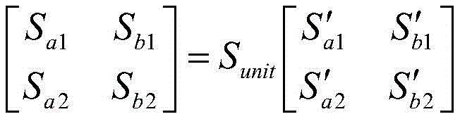
Specifically, the space vector modulator generates the power routing switch states S (a, b) of each single-stage single-phase matrix converter 02 according to the following first switch state algorithm formula:

wherein the content of the first and second substances, an electrical energy routing switch state S (a, b) for a single-stage single-phase matrix converter;
 a first indirect switching state S' (a, b); sunitIs in unit switch state, when the first matrix converter interface is used as output interface, SunitTake the first unit switch state Sunit1,
 When the first matrix converter interface is used as the input interface, SunitTake the second unit switch state Sunit2,
 I.e. the second unit switch state Sunit2And a first unit switch state Sunit1At a constant 50% duty cycle
 And
And alternating between them.
In the embodiment of the invention, the state S is switched by the second unit switchunit2And a first unit switch state Sunit1With a constant 50% duty cycle And
And in an alternating relationship, a complementary control relationship is established between the matrix converters forming the output interface and the matrix converters forming the input interface, the second unit switch state Sunit2And a first unit switch state Sunit1The complementary relationship is established between the high-frequency alternating current bus 01 and the high-frequency square wave, so that the high-frequency transformer can operate normally.
Referring to fig. 4, the space vector modulation strategy of the indirect matrix converter of the single-stage single-phase matrix converter includes two effective state vectorsQuantity V1And V2And two zero state vectors V3And V4Wherein V is1~V4Are respectively specifically V1(1001)、V2(0110)、V3(1010) And V4(0101),V1(1001) Represents S'a1=ON,S′a2=OFF,S′b1=OFF,S′b2=ON;V2(0110) Represents S'a1=OFF,S′a2=ON,S′b1=ON,S′b2=OFF;V3(1010) Represents S'a1=ON,S′a2=OFF,S′b1=ON,S′b2=OFF;V4(0101) Represents S'a1=OFF,S′a2=ON,S′b1=OFF,S′b2And (5) turning ON. Two valid state vectors V1And V2The space is divided into two sectors I and II, reference voltage vector VrefWhen falling into any sector, the reference voltage vector VrefAre all composed of a valid state vector VaAnd two zero state vectors VZ1And VZ2Synthetic, valid state vector VaBy the resulting effective state duty cycle d21To modulate a first indirect switching state S' (a, b), zero state vector V, of a single-stage, single-phase matrix converterZ1And VZ2By the zero state duty cycle d after synthesis20To modulate a first indirect switching state S' (a, b) of a single-stage, single-phase matrix converter, the resultant effective state duty cycle d21And the synthesized zero-state duty cycle d20The synthesis formula of (A) is as follows:
d21=d′21·d11+d′21·d12
d20=d′20·d11+d′20·d12+d10。
further, active state duty cycle d'21And zero state duty cycle d'20The calculation formula of (2) is as follows:

d′20=1-d′21
wherein M is2Modulation factor, V, representing the inverter stage of an indirect matrix converteromThe amplitude of the alternating current output voltage of the single-stage single-phase matrix converter, the voltage amplitude of the high frequency alternating current bus. The power routing switch state S (a, b) of the single-stage single-phase matrix converter is modulated as shown in the following table:
electric energy routing switch state S (a, b) modulation meter of meter I single-stage single-phase matrix converter

Similarly, the expression of the first indirect switching state S' (a, b) of the single-stage single-phase matrix converter, the resulting effective state duty cycle d21And the synthesized zero-state duty cycle d20The synthetic formula of (a) and the correlation formula of the state S (a, b) of the power routing switch of the single-stage single-phase matrix converter 02 take into account the coupling to the primary side and the secondary voltage v of the high-frequency transformersAnd a reference voltage vector VrefAfter the sector, the corresponding valid state vector V can be selected from the table IaAnd zero state vector VZ1And VZ2The control signal for the switch state S (a, b) is routed as power for a single-stage single-phase matrix converter.
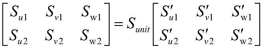
Similarly, the space vector modulator generates the power routing switch state S (u, v, w) of each single-stage three-phase matrix converter 03 according to the following second switch state algorithm formula:

wherein the content of the first and second substances, a switch state S (u, v, w) for the power routing of the single-stage three-phase matrix converter;
 a second indirect switch state S' (u, v, w); sunitIs in a unit switch state, when the second matrix converter interface is used as an output interface, SunitTake the first unit switch state Sunit1,
 When the second matrix converter interface is used as the input interface, SunitTake the second unit switch state Sunit2,
 I.e. the second unit switch state Sunit2And a first unit switch state Sunit1At a constant 50% duty cycle
 And
And alternating between them.
In the embodiment of the invention, the state S is switched by the second unit switchunit2And a first unit switch state Sunit1With a constant 50% duty cycle And
And in an alternating relationship, a complementary control relationship being established between the matrix converters forming the input interface and the matrix converters forming the output interface, the second unit switching state Sunit2And a first unit switch state Sunit1The complementary relationship is established between the high-frequency alternating current bus 01 and the high-frequency square wave which is required by the operation of the high-frequency transformer, so that the normal operation of the high-frequency transformer is ensuredAnd (6) rows.
Referring to fig. 5, in the embodiment of the present invention, the space vector modulation strategy of the indirect matrix converter of the single-stage three-phase matrix converter includes six effective state vectors I1~I6And three zero state vectors I7~I9Wherein, I1~I9Are respectively specifically I1(100001)、I2(001001)、I3(011000)、I4(010010)、I5(000110)、I6(100100)、I7(110000)、I8(001100) and I9(000011),I1(100001) represents S'u1=ON,S′u2=OFF,S′v1=OFF,S′v2=OFF,S′w1=OFF,S′w2=ON;I2(001001) represents S'u1=OFF,S′u2=OFF,S′v1=ON,S′v2=OFF,S′w1=OFF,S′w2=ON;I3(011000) denotes S'u1=OFF,S′u2=ON,S′v1=ON,S′v2=OFF,S′w1=OFF,S′w2=OFF;I4(010010) represents S'u1=OFF,S′u2=ON,S′v1=OFF,S′v2=OFF,S′w1=ON,S′w2=OFF;I5(000110) represents S'u1=OFF,S′u2=OFF,S′v1=OFF,S′v2=ON,S′w1=ON,S′w2=OFF;I6(100100) represents S'u1=ON,S′u2=OFF,S′v1=OFF,S′v2=ON,S′w1=OFF,S′w2=OFF;I7(110000) represents S'u1=ON,S′u2=ON,S′v1=OFF,S′v2=OFF,S′w1=OFF,S′w2=OFF;I8(001100) represents S'u1=OFF,S′u2=OFF,S′v1=ON,S′v2=ON,S′w1=OFF,S′w2=OFF;I9(000011) represents S'u1=OFF,S′u2=OFF,S′v1=OFF,S′v2=OFF,S′w1=ON,S′w2And (5) turning ON. Six significant state vectors I1~I6The space is divided into six sectors I-VI, reference current vector IrefWhen falling into any sector, the reference current vector IrefTwo valid state vectors I, both adjacent to the sectoraAnd IbAnd two zero state vectors IZ1And IZ2Synthetic, valid state vector IaAnd IbRespectively by effective state duty cycle d11And d12To modulate the second indirect switching state S' (u, v, w), zero state vector I of the single-stage three-phase matrix converterZ1And IZ2By zero state duty cycle d10To modulate the second indirect switch state S' (u, v, w), the effective state duty cycle d11And d12And zero state duty cycle d10The calculation formula of (2) is as follows:
d11=M1sin(π/3-θi)
d12=M1sin(θi)
d10=1-(d11+d12)
wherein the content of the first and second substances, M1representing the modulation factor of the rectifier stage of an indirect matrix converter, IpRepresenting the absolute value of the high-frequency AC bus current, IsmRepresenting the amplitude, theta, of three-phase AC current of a single-stage three-phase matrix converteriRepresenting a reference current vector IrefAnd a valid vector IaThe included angle of (a). The power routing switch state S (u, v, w) of the single-stage three-phase matrix converter is modulated as shown in the following table:
table II electric energy routing switch state S (u, v, w) modulation table of single-stage three-phase matrix converter

Table II lists all possible switch states of the power routing switch states S (u, v, w) of the single-stage three-phase matrix converter for a given control signal for the bidirectional switches of the single-stage three-phase matrix converter. Taking sector I and positive polarity voltage as an example, see I in FIG. 56And I1Are respectively I in Table IaAnd IbBased on the minimum switching times of the switch, the ratio of I to II8And I9Are respectively selected as zero state vector IZ1And IZ2。
In addition, the transformation ratio 1: n of each high-frequency isolation transformer 04 is the average direct current voltage of each single-stage single-phase matrix converter/single-stage three-phase matrix converter Voltage amplitude of high frequency AC bus
 The ratio of (a) to (b). The specific calculation method is as follows:
firstly, the average DC voltage of each port matrix converter is calculated For example, for three-phase AC, single-phase AC and DC ports, the average DC voltage
 Respectively calculated by the following formulas:
average dc voltage of single-phase current-intersecting port:
average dc voltage of the first, second, and third three-phase ac ports:
average dc voltage of dc port:
wherein M is1Is the modulation index, U, of the convertersmIs the port ac voltage amplitude or the dc voltage average, is the power factor of the port.
Obtaining the voltage amplitude of the high frequency AC bus And each single-stage single-phase matrix converter/single-stage three-phase matrix converter average DC voltage
 Voltage amplitude of high frequency AC bus
 The ratio of (a) to (b), i.e.,
referring to fig. 6, fig. 6 is a schematic diagram of an electrical structure of a power router based on a matrix converter in a plccs software simulation example according to another embodiment of the present invention. Specifically, the power router in the PLECS software simulation example comprises: a second three-phase ac port for interfacing with a 380V/50Hz three-phase ac low-voltage power grid, a single phase ac port for interfacing with a 120V/60Hz single-phase ac load, a dc port for interfacing with a 400V dc load, and a third three-phase ac port for interfacing with a 380V/50Hz load; the switching frequency of the matrix converter in the embodiment is 10kHz, so that a high-frequency alternating current bus of 10kHz/400V is formed; the transformation ratios 1: n of the high-frequency isolation transformers of the ports calculated according to the method are 1:1.4, 1:1.75, 1:2.2 and 1:2 respectively.
FIG. 7 is a waveform diagram of 10kHz/400V high-frequency AC bus bar obtained from the simulation result of the simulation example shown in FIG. 6; fig. 8a and 8b are graphs showing voltage and current waveforms of a 380V/50Hz three-phase ac power supply port, respectively, according to the simulation results of the simulation example shown in fig. 6; FIGS. 9a and 9b are graphs of voltage and current waveforms, respectively, at a 120V/60Hz single-phase AC load port, as a result of a simulation of the example of the simulation shown in FIG. 6; FIGS. 10a and 10b are graphs of voltage and current waveforms, respectively, at a 400V DC load port, obtained as a result of a simulation of the example simulation shown in FIG. 6; fig. 11a and 11b are graphs of voltage and current waveforms of a 380V/50Hz three-phase ac load port, respectively, obtained as a result of the simulation example shown in fig. 6. The results show that the conversion of voltage amplitude and frequency is realized under the condition that each port is provided with a 10kHz/400V high-frequency alternating current bus, and the single-stage matrix converter runs at rated voltage amplitude and frequency, so that the feasibility and the effectiveness of the electric energy router provided by the embodiment of the invention are shown. And the whole electric energy router has no direct current bus capacitor, compact structure and few switching devices, and if a wide bandgap silicon carbide switching device is used, the bus voltage frequency can be increased, so that the volumes of passive devices and high-frequency isolation transformers are further reduced, and the efficiency of the electric energy router is improved.
The embodiment of the invention has the following advantages:
according to the electric energy router based on the matrix converter, the power electronic interface of the electric energy router is completely composed of the single-stage matrix converter, and single-stage power conversion is beneficial to improving the efficiency; the high-frequency alternating current bus greatly reduces the parameters and the volume of passive devices, particularly reduces the volume and the weight of an isolation transformer; the direct current bus electrolytic capacitor with large capacity does not exist, the reliability is improved, and the service life is prolonged; the medium-voltage power grid is directly butted, so that fewer power devices are used, and the structure is compact; the unified interface topology is convenient for installation, debugging and maintenance.
The above-mentioned embodiments, objects, technical solutions and advantages of the present invention are further described in detail, it should be understood that the above-mentioned embodiments are only exemplary embodiments of the present invention, and are not intended to limit the scope of the present invention, and any modifications, equivalent substitutions, improvements and the like made on the basis of the technical solutions of the present invention should be included in the scope of the present invention.
Claims (10)
1. A matrix converter based power router, the power router comprising: a high frequency ac bus and at least two plug interfaces connected to said high frequency ac bus, said plug interfaces comprising: the high-frequency alternating-current bus comprises at least one input interface and at least one output interface, wherein the input interface inputs electric energy to the high-frequency alternating-current bus, and the input interface outputs the electric energy from the high-frequency alternating-current bus; the output interface includes: at least one first matrix converter interface formed by a single-stage single-phase matrix converter and/or at least one second matrix converter interface formed by a single-stage three-phase matrix converter; each plug interface is connected to the high-frequency alternating current bus through a high-frequency isolation transformer with the transformation ratio of 1: n.
2. The power router of claim 1, wherein the first matrix converter interface comprises: at least one dc port for interfacing with a dc power source or load and at least one single phase ac cross-current port for interfacing with a single phase ac power grid or load.
3. The power router of claim 1, wherein: the second matrix converter interface comprises at least one first three-phase ac port for interfacing with a three-phase ac medium voltage grid, at least one second three-phase ac port for interfacing with a three-phase ac low voltage grid, and at least one third three-phase ac port for interfacing with a three-phase ac low voltage load.
4. The power router of claim 1, further comprising: the space vector modulator is respectively connected to each single-stage single-phase matrix converter and each single-stage three-phase matrix converter; the space vectorThe modulator generates an indirect switching state S 'for each matrix converter by using a space vector modulation strategy of the indirect matrix converter, and the indirect switching state S' and a unit switching state SunitCombining to obtain an electric energy route switch state S; and at the beginning of the next control period, the electric energy routing switch state S is distributed to the corresponding matrix converter by the space vector modulator for switch control.
5. The power router of claim 4 wherein the space vector modulator generates the power routing switch states S (a, b) for each single-stage single-phase matrix converter according to the following first switch state algorithm formula:
wherein the content of the first and second substances,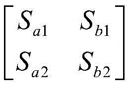 an electrical energy routing switch state S (a, b) for a single-stage single-phase matrix converter;
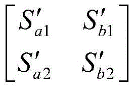 a first indirect switching state S' (a, b); sunitIs in unit switch state, when the first matrix converter interface is used as output interface, SunitTake the first unit switch state Sunit1,
 When the first matrix converter interface is used as the input interface, SunitTake the second unit switch state Sunit2,
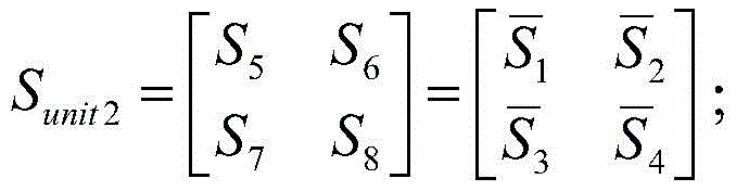
The space vector modulator generates an electric energy routing switch state S (u, v, w) of each single-stage three-phase matrix converter according to the following second switch state algorithm formula:

wherein the content of the first and second substances, a switch state S (u, v, w) for the power routing of the single-stage three-phase matrix converter;
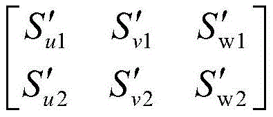 a second indirect switch state S' (u, v, w); sunitIs in a unit switch state, when the second matrix converter interface is used as an output interface, SunitTake the first unit switch state Sunit1,
 When the second matrix converter interface is used as the input interface, SunitTake the second unit switch state Sunit2,
6. The electrical energy router of claim 1, wherein the high frequency isolation transformer has a transformation ratio of 1: n of each single-stage single-phase matrix converter/single-stage three-phase matrix converter average DC voltage Voltage amplitude of high frequency AC bus
 The ratio of (a) to (b).
7. A method for matrix converter based routing of electrical energy, the method comprising:
connect two at least plug interfaces through a high frequency interchange generating line, plug interface includes: the high-frequency alternating-current bus comprises at least one input interface and at least one output interface, wherein the input interface inputs electric energy to the high-frequency alternating-current bus, and the input interface outputs the electric energy from the high-frequency alternating-current bus; the output interface includes: at least one first matrix converter interface formed by a single-stage single-phase matrix converter and/or at least one second matrix converter interface formed by a single-stage three-phase matrix converter;
a three-phase alternating current port is used as a second matrix converter interface to be butted with a three-phase alternating current medium voltage power grid; or a three-phase alternating current port is used as a second matrix converter interface and is used for butting a three-phase alternating current low-voltage power grid;
the three-phase alternating current low-voltage load is butted by taking at least one three-phase alternating current port as a second matrix converter interface;
connecting a direct current power supply or a load by using at least one direct current port as a first matrix converter interface; and
docking a single-phase alternating current power grid or a load through at least one single-phase current-intersecting port as a first matrix converter interface;
each first matrix converter interface and each second matrix converter interface are connected to the high-frequency alternating current bus through a high-frequency isolation transformer with the transformation ratio of 1: n.
8. The method of claim 7, further comprising:
generating an indirect switch state S' for each matrix converter by using a space vector modulation strategy of an indirect matrix converter;
the indirect switching state S' is compared with the unit switching state SunitCombining to obtain the electric energy routing switch state S of each matrix converter;
and at the beginning of the next control period, distributing the electric energy routing switch state S to the corresponding matrix converter for switching control.
9. The method of claim 8, wherein the space vector modulator generates the power routing switch states S (a, b) for each single-stage single-phase matrix converter according to the following first switch state algorithm formula:
wherein the content of the first and second substances, an electrical energy routing switch state S (a, b) for a single-stage single-phase matrix converter;
 a first indirect switching state S' (a, b); sunitIs in unit switch state, when the first matrix converter interface is used as output interface, SunitTake the first unit switch state Sunit1,
 When the first matrix converter interface is used as the input interface, SunitTake the second unit switch state Sunit2,
The space vector modulator generates an electric energy routing switch state S (u, v, w) of each single-stage three-phase matrix converter according to the following second switch state algorithm formula:
wherein the content of the first and second substances, a switch state S (u, v, w) for the power routing of the single-stage three-phase matrix converter;
 a second indirect switch state S' (u, v, w); sunitIs in a unit switch state, when the second matrix converter interface is used as an output interface, SunitTake the first unit switch state Sunit1,
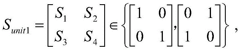 When the second matrix converter interface is used as the input interface, SunitTake the second unit switch state Sunit2,
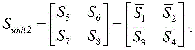
10. The method as claimed in claim 7, wherein the transformation ratio of the high-frequency isolation transformer is 1: n, and the transformation ratio is the average DC voltage of each single-stage single-phase matrix converter/single-stage three-phase matrix converter Voltage amplitude of high frequency AC bus
 The ratio of (a) to (b).
Priority Applications (1)
| Application Number | Priority Date | Filing Date | Title |
|---|---|---|---|
| CN202011073332.4A CN112186771B (en) | 2020-10-09 | 2020-10-09 | Electric energy router based on matrix converter and electric energy routing method |
Applications Claiming Priority (1)
| Application Number | Priority Date | Filing Date | Title |
|---|---|---|---|
| CN202011073332.4A CN112186771B (en) | 2020-10-09 | 2020-10-09 | Electric energy router based on matrix converter and electric energy routing method |
Publications (2)
| Publication Number | Publication Date |
|---|---|
| CN112186771A true CN112186771A (en) | 2021-01-05 |
| CN112186771B CN112186771B (en) | 2022-11-25 |
Family
ID=73948589
Family Applications (1)
| Application Number | Title | Priority Date | Filing Date |
|---|---|---|---|
| CN202011073332.4A Active CN112186771B (en) | 2020-10-09 | 2020-10-09 | Electric energy router based on matrix converter and electric energy routing method |
Country Status (1)
| Country | Link |
|---|---|
| CN (1) | CN112186771B (en) |
Cited By (2)
| Publication number | Priority date | Publication date | Assignee | Title |
|---|---|---|---|---|
| CN113098044A (en) * | 2021-03-26 | 2021-07-09 | 广东电网有限责任公司 | Current converter-based power distribution system and power distribution method |
| CN114189143A (en) * | 2021-12-08 | 2022-03-15 | 国网山东省电力公司电力科学研究院 | Three-port electric energy router device |
Citations (21)
| Publication number | Priority date | Publication date | Assignee | Title |
|---|---|---|---|---|
| CN101013856A (en) * | 2006-12-14 | 2007-08-08 | 上海交通大学 | Cascaded multiple matrix converter |
| CN101951165A (en) * | 2010-09-16 | 2011-01-19 | 上海交通大学 | Single-phase alternating current converter of direct current link |
| CN101951163A (en) * | 2010-09-16 | 2011-01-19 | 上海交通大学 | Single-phase alternating current converter for alternating current link |
| CN102751855A (en) * | 2011-04-20 | 2012-10-24 | 通用汽车环球科技运作有限责任公司 | Discharging a dc bus capacitor of an electrical converter system |
| CN103036304A (en) * | 2011-09-30 | 2013-04-10 | 首瑞(北京)投资管理集团有限公司 | Alternating current power supply system for substation |
| CN103178720A (en) * | 2013-03-08 | 2013-06-26 | 卧龙电气集团股份有限公司 | High-voltage matrix converter |
| CN103208816A (en) * | 2013-04-08 | 2013-07-17 | 浙江大学 | Power collection and transmission system for wind power plant and voltage control method for alternating current generatrix of power collection and transmission system |
| CN103647461A (en) * | 2013-12-06 | 2014-03-19 | 西南交通大学 | Control method and apparatus of AC-DC series resonance matrix converter |
| CN103701145A (en) * | 2014-01-02 | 2014-04-02 | 浙江大学 | Mixed MMC-based mixed direct current power transmission system |
| CN104993712A (en) * | 2015-07-02 | 2015-10-21 | 江苏元凯电气科技有限公司 | Three-phase to single-phase AC converter control method |
| CN106877690A (en) * | 2017-04-21 | 2017-06-20 | 清华大学 | Multiport current converter for connecting a plurality of alternating current circuit |
| CN106972603A (en) * | 2017-05-11 | 2017-07-21 | 湖南大学 | The V2G chargers and its control method of a kind of use High Frequency Link matrix converter |
| CN107017797A (en) * | 2017-03-22 | 2017-08-04 | 燕山大学 | Accumulator cell charging and discharging single-phase high frequency chain matrix converter separate type vector modulation method |
| CN107070253A (en) * | 2017-03-30 | 2017-08-18 | 南京航空航天大学 | A kind of Indirect Matrix Converter and its control method with direct current output function |
| CN206471841U (en) * | 2016-12-30 | 2017-09-05 | 中国移动通信集团设计院有限公司 | Electric energy router and micro-capacitance sensor structure |
| CN108011527A (en) * | 2017-12-27 | 2018-05-08 | 北京金风科创风电设备有限公司 | Converter, direct-drive wind generating set and power transmission system |
| CN108390572A (en) * | 2018-01-31 | 2018-08-10 | 南京航空航天大学 | Active third-harmonic zero-sequence voltage matrix converter input current waveform optimizes topological structure |
| CN108718083A (en) * | 2018-06-15 | 2018-10-30 | 东北电力大学 | Series connection multiport DC power flow controller based on MMC |
| CN109039115A (en) * | 2018-08-07 | 2018-12-18 | 北京航空航天大学 | A kind of isolated converter of high-frequency AC and its uniform spaces Vector Modulation strategy |
| CN110556833A (en) * | 2019-09-05 | 2019-12-10 | 北京国电光宇机电设备有限公司 | Multi-port microgrid energy router |
| CN111614112A (en) * | 2020-06-11 | 2020-09-01 | 内蒙古工业大学 | Virtual synchronous generator control method and system of matrix converter |
-
2020
- 2020-10-09 CN CN202011073332.4A patent/CN112186771B/en active Active
Patent Citations (21)
| Publication number | Priority date | Publication date | Assignee | Title |
|---|---|---|---|---|
| CN101013856A (en) * | 2006-12-14 | 2007-08-08 | 上海交通大学 | Cascaded multiple matrix converter |
| CN101951165A (en) * | 2010-09-16 | 2011-01-19 | 上海交通大学 | Single-phase alternating current converter of direct current link |
| CN101951163A (en) * | 2010-09-16 | 2011-01-19 | 上海交通大学 | Single-phase alternating current converter for alternating current link |
| CN102751855A (en) * | 2011-04-20 | 2012-10-24 | 通用汽车环球科技运作有限责任公司 | Discharging a dc bus capacitor of an electrical converter system |
| CN103036304A (en) * | 2011-09-30 | 2013-04-10 | 首瑞(北京)投资管理集团有限公司 | Alternating current power supply system for substation |
| CN103178720A (en) * | 2013-03-08 | 2013-06-26 | 卧龙电气集团股份有限公司 | High-voltage matrix converter |
| CN103208816A (en) * | 2013-04-08 | 2013-07-17 | 浙江大学 | Power collection and transmission system for wind power plant and voltage control method for alternating current generatrix of power collection and transmission system |
| CN103647461A (en) * | 2013-12-06 | 2014-03-19 | 西南交通大学 | Control method and apparatus of AC-DC series resonance matrix converter |
| CN103701145A (en) * | 2014-01-02 | 2014-04-02 | 浙江大学 | Mixed MMC-based mixed direct current power transmission system |
| CN104993712A (en) * | 2015-07-02 | 2015-10-21 | 江苏元凯电气科技有限公司 | Three-phase to single-phase AC converter control method |
| CN206471841U (en) * | 2016-12-30 | 2017-09-05 | 中国移动通信集团设计院有限公司 | Electric energy router and micro-capacitance sensor structure |
| CN107017797A (en) * | 2017-03-22 | 2017-08-04 | 燕山大学 | Accumulator cell charging and discharging single-phase high frequency chain matrix converter separate type vector modulation method |
| CN107070253A (en) * | 2017-03-30 | 2017-08-18 | 南京航空航天大学 | A kind of Indirect Matrix Converter and its control method with direct current output function |
| CN106877690A (en) * | 2017-04-21 | 2017-06-20 | 清华大学 | Multiport current converter for connecting a plurality of alternating current circuit |
| CN106972603A (en) * | 2017-05-11 | 2017-07-21 | 湖南大学 | The V2G chargers and its control method of a kind of use High Frequency Link matrix converter |
| CN108011527A (en) * | 2017-12-27 | 2018-05-08 | 北京金风科创风电设备有限公司 | Converter, direct-drive wind generating set and power transmission system |
| CN108390572A (en) * | 2018-01-31 | 2018-08-10 | 南京航空航天大学 | Active third-harmonic zero-sequence voltage matrix converter input current waveform optimizes topological structure |
| CN108718083A (en) * | 2018-06-15 | 2018-10-30 | 东北电力大学 | Series connection multiport DC power flow controller based on MMC |
| CN109039115A (en) * | 2018-08-07 | 2018-12-18 | 北京航空航天大学 | A kind of isolated converter of high-frequency AC and its uniform spaces Vector Modulation strategy |
| CN110556833A (en) * | 2019-09-05 | 2019-12-10 | 北京国电光宇机电设备有限公司 | Multi-port microgrid energy router |
| CN111614112A (en) * | 2020-06-11 | 2020-09-01 | 内蒙古工业大学 | Virtual synchronous generator control method and system of matrix converter |
Non-Patent Citations (2)
| Title |
|---|
| YUSHAN LIU等: "A Simple Space Vector Modulation of High-Frequency AC Linked Three-Phase-to-Single-Phase/DC Converter", 《IEEE ACCESS》 * |
| 邓文浪等: "基于三相-单相矩阵变换器的三端口变换器及其在V2G 中的应用", 《电工技术学报》 * |
Cited By (3)
| Publication number | Priority date | Publication date | Assignee | Title |
|---|---|---|---|---|
| CN113098044A (en) * | 2021-03-26 | 2021-07-09 | 广东电网有限责任公司 | Current converter-based power distribution system and power distribution method |
| CN113098044B (en) * | 2021-03-26 | 2023-01-24 | 广东电网有限责任公司 | Current converter-based power distribution system and power distribution method |
| CN114189143A (en) * | 2021-12-08 | 2022-03-15 | 国网山东省电力公司电力科学研究院 | Three-port electric energy router device |
Also Published As
| Publication number | Publication date |
|---|---|
| CN112186771B (en) | 2022-11-25 |
Similar Documents
| Publication | Publication Date | Title |
|---|---|---|
| CN109167364B (en) | Three-port flexible multi-state switching device based on bridge arm multiplexing and hybrid cascading | |
| CN112186771B (en) | Electric energy router based on matrix converter and electric energy routing method | |
| WO2021147514A1 (en) | Modular multilevel alternating current-direct current conversion system | |
| CN109980948A (en) | A kind of five port electric power electric transformer of three Coupling Between Phases | |
| CN110556833A (en) | Multi-port microgrid energy router | |
| CN113346764A (en) | Medium voltage converter topological structure based on high frequency magnetic coupling module | |
| CN109039115A (en) | A kind of isolated converter of high-frequency AC and its uniform spaces Vector Modulation strategy | |
| CN109194137A (en) | A kind of modular solid-state transformer based on three level of half-bridge cascade connection type | |
| Tanta et al. | Modular multilevel converter in electrified railway systems: applications of rail static frequency converters and rail power conditioners | |
| Kadandani et al. | Solid state transformer: An overview of circuit configurations and applications | |
| CN116488224A (en) | Multiport alternating current-direct current hybrid converter device and multiport alternating current-direct current hybrid system | |
| CN110247416B (en) | Multi-port direct-current flexible multi-state switch device based on bifurcated bridge arm structure | |
| CN110247418B (en) | AC/DC hybrid power distribution network based on flexible multi-state switch and control test method | |
| Akshatha et al. | A unified ac-dc microgrid architecture for distribution of ac and dc power on the same line | |
| WO2022001834A1 (en) | Power supply and distribution system for data center | |
| WO2022033185A1 (en) | Module-shared flexible loop closing controller topology for power grid | |
| CN113890122A (en) | Alternating current-direct current multiport power distribution system for office residential area | |
| CN109474193A (en) | A kind of modular solid-state transformer based on three level of diode clamp bit-type | |
| Xu et al. | Research on flexible medium-voltage DC distribution technology based shore-to-ship power supply system | |
| Watson et al. | Experimental implementation of a multilevel converter for power system integration | |
| Idehen et al. | The series bridge converter: A compact and economic VSC-HVDC converter | |
| Shojaei et al. | A modular solid state transformer with a single-phase medium-frequency transformer | |
| Miao et al. | Research on power electronic transformer applied in AC/DC hybrid distribution networks | |
| WO2021143144A1 (en) | Interline power transfer apparatus applicable to multiple groups of multi-circuit lines | |
| Chong et al. | A Power Conversion System For Large-Scale Reversible SOFC Energy Storage System |
Legal Events
| Date | Code | Title | Description |
|---|---|---|---|
| PB01 | Publication | ||
| PB01 | Publication | ||
| SE01 | Entry into force of request for substantive examination | ||
| SE01 | Entry into force of request for substantive examination | ||
| GR01 | Patent grant | ||
| GR01 | Patent grant |