CN112166360B - Optical system and optical equipment - Google Patents
Optical system and optical equipment Download PDFInfo
- Publication number
- CN112166360B CN112166360B CN201880093788.1A CN201880093788A CN112166360B CN 112166360 B CN112166360 B CN 112166360B CN 201880093788 A CN201880093788 A CN 201880093788A CN 112166360 B CN112166360 B CN 112166360B
- Authority
- CN
- China
- Prior art keywords
- lens
- optical system
- group
- conditional expression
- air
- Prior art date
- Legal status (The legal status is an assumption and is not a legal conclusion. Google has not performed a legal analysis and makes no representation as to the accuracy of the status listed.)
- Active
Links
Images


Classifications
-
- G—PHYSICS
- G02—OPTICS
- G02B—OPTICAL ELEMENTS, SYSTEMS OR APPARATUS
- G02B13/00—Optical objectives specially designed for the purposes specified below
- G02B13/18—Optical objectives specially designed for the purposes specified below with lenses having one or more non-spherical faces, e.g. for reducing geometrical aberration
-
- G—PHYSICS
- G02—OPTICS
- G02B—OPTICAL ELEMENTS, SYSTEMS OR APPARATUS
- G02B9/00—Optical objectives characterised both by the number of the components and their arrangements according to their sign, i.e. + or -
- G02B9/64—Optical objectives characterised both by the number of the components and their arrangements according to their sign, i.e. + or - having more than six components
-
- G—PHYSICS
- G02—OPTICS
- G02B—OPTICAL ELEMENTS, SYSTEMS OR APPARATUS
- G02B13/00—Optical objectives specially designed for the purposes specified below
- G02B13/04—Reversed telephoto objectives
-
- G—PHYSICS
- G02—OPTICS
- G02B—OPTICAL ELEMENTS, SYSTEMS OR APPARATUS
- G02B27/00—Optical systems or apparatus not provided for by any of the groups G02B1/00 - G02B26/00, G02B30/00
- G02B27/0025—Optical systems or apparatus not provided for by any of the groups G02B1/00 - G02B26/00, G02B30/00 for optical correction, e.g. distorsion, aberration
- G02B27/005—Optical systems or apparatus not provided for by any of the groups G02B1/00 - G02B26/00, G02B30/00 for optical correction, e.g. distorsion, aberration for correction of secondary colour or higher-order chromatic aberrations
-
- G—PHYSICS
- G02—OPTICS
- G02B—OPTICAL ELEMENTS, SYSTEMS OR APPARATUS
- G02B3/00—Simple or compound lenses
- G02B3/12—Fluid-filled or evacuated lenses
Landscapes
- Physics & Mathematics (AREA)
- General Physics & Mathematics (AREA)
- Optics & Photonics (AREA)
- Lenses (AREA)
Abstract
Description
技术领域technical field
本发明涉及光学系统、光学设备以及光学系统的制造方法。The present invention relates to an optical system, an optical device and a manufacturing method of the optical system.
背景技术Background technique
以往,在大口径的摄影镜头中,公知有通过在双高斯结构中增加透镜来对各像差进行校正的技术(例如,参照专利文献1。)。但是,伴随近年来的拍摄元件的高像素化,期望能够进一步良好地对各像差进行校正的大口径的摄影镜头。Conventionally, in a large-diameter photographic lens, a technique of correcting various aberrations by adding lenses to a double Gauss structure is known (for example, refer to Patent Document 1). However, with the increase in the number of pixels of imaging elements in recent years, there is a demand for a large-diameter imaging lens capable of correcting various aberrations more favorably.
现有技术文献prior art literature
专利文献patent documents
专利文献1:日本特开平11-211978号公报Patent Document 1: Japanese Patent Application Laid-Open No. 11-211978
发明内容Contents of the invention
本发明的第1方式是一种光学系统,其中,A first aspect of the present invention is an optical system wherein,
从物体侧依次由前组和后组构成,所述前组具有正的光焦度,Consisting sequentially from the object side of a front group and a rear group, the front group having a positive optical power,
在进行对焦时,所述前组沿着光轴移动,When focusing, the front group moves along the optical axis,
且满足以下的条件式:And satisfy the following conditions:
0.90<fF/f<1.500.90<fF/f<1.50
其中,in,
fF:所述前组的焦距fF: focal length of the front group
f:所述光学系统的整个系统的焦距。f: focal length of the entire system of the optical system.
另外,本发明的第2方式是一种光学系统的制造方法,In addition, a second aspect of the present invention is a method of manufacturing an optical system,
该光学系统从物体侧依次由前组和后组构成,所述前组具有正的光焦度,The optical system is sequentially composed of a front group and a rear group from the object side, the front group having a positive optical power,
该光学系统以在进行对焦时所述前组沿着光轴移动的方式构成,并以满足以下的条件式的方式构成:This optical system is configured so that the front group moves along the optical axis when focusing, and is configured to satisfy the following conditional expression:
0.90<fF/f<1.500.90<fF/f<1.50
其中,in,
fF:所述前组的焦距fF: focal length of the front group
f:所述光学系统的整个系统的焦距。f: focal length of the entire system of the optical system.
附图说明Description of drawings
图1是第1实施例的光学系统的剖视图。Fig. 1 is a sectional view of an optical system of a first embodiment.
图2A及图2B分别是第1实施例的光学系统的无限远物体对焦时和近距离物体对焦时的各像差图。2A and 2B are aberration diagrams of the optical system of the first embodiment when focusing on an object at infinity and when focusing on a short-distance object, respectively.
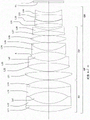
图3是第2实施例的光学系统的剖视图。Fig. 3 is a sectional view of the optical system of the second embodiment.
图4A及图4B分别是第2实施例的光学系统的无限远物体对焦时和近距离物体对焦时的各像差图。4A and 4B are aberration diagrams of the optical system of the second embodiment when focusing on an object at infinity and when focusing on a short-distance object, respectively.
图5是第3实施例的光学系统的剖视图。Fig. 5 is a sectional view of the optical system of the third embodiment.
图6A及图6B分别是第3实施例的光学系统的无限远物体对焦时和近距离物体对焦时的各像差图。6A and 6B are aberration diagrams of the optical system of the third embodiment when focusing on an object at infinity and when focusing on a short-distance object, respectively.
图7是第4实施例的光学系统的剖视图。Fig. 7 is a sectional view of the optical system of the fourth embodiment.
图8A及图8B分别是第4实施例的光学系统的无限远物体对焦时和近距离物体对焦时的各像差图。8A and 8B are aberration diagrams of the optical system of the fourth embodiment when focusing on an object at infinity and when focusing on a short-distance object, respectively.
图9是示出具备光学系统的相机结构的图。FIG. 9 is a diagram showing the configuration of a camera including an optical system.
图10是示出光学系统的制造方法的概略的流程图。FIG. 10 is a flowchart illustrating an outline of a method of manufacturing an optical system.
具体实施方式detailed description
以下,对本发明的实施方式的光学系统、光学设备以及光学系统的制造方法进行说明。Hereinafter, the optical system, the optical device, and the manufacturing method of the optical system according to the embodiments of the present invention will be described.
本实施方式的光学系统构成为,从物体侧依次由前组和后组构成,所述前组具有正的光焦度,在进行对焦时,所述前组沿着光轴移动,且满足以下的条件式(1)。The optical system of this embodiment is composed of a front group and a rear group in order from the object side, the front group has a positive refractive power, and when focusing, the front group moves along the optical axis, and satisfies the following conditional formula (1).
(1)0.90<fF/f<1.50(1) 0.90<fF/f<1.50
其中,in,
fF:所述前组的焦距fF: focal length of the front group
f:所述光学系统的整个系统的焦距f: focal length of the entire system of the optical system
本实施方式的光学系统通过从物体侧依次由前组和后组构成,所述前组具有正的光焦度,在进行对焦时,所述前组沿着光轴移动的结构,从而能够抑制从无限远物体向近距离物体进行对焦时的各像差的变动,特别是能够良好地对球面像差和像面弯曲进行校正。The optical system of this embodiment is composed of a front group and a rear group in order from the object side, the front group has a positive refractive power, and the front group moves along the optical axis when focusing, so that it can suppress Variations in various aberrations when focusing from an object at infinity to a short-distance object, especially spherical aberration and curvature of field can be corrected favorably.
上述条件式(1)是规定前组的焦距与光学系统的整个系统的焦距的比的条件式。本实施方式的光学系统通过满足条件式(1),从而能够良好地对以球面像差和像面弯曲为首的各像差进行校正。The conditional expression (1) above is a conditional expression that defines the ratio of the focal length of the front group to the focal length of the entire optical system. The optical system of the present embodiment can satisfactorily correct various aberrations including spherical aberration and curvature of field by satisfying the conditional expression (1).
当本实施方式的光学系统的条件式(1)的对应值超过上限值时,前组的光焦度变弱,无法充分地对像面弯曲进行校正。另外,通过将条件式(1)的上限值设定为1.48,从而能够更可靠地得到本实施方式的效果。另外,为了更可靠地得到本实施方式的效果,优选的是,使条件式(1)的上限值为1.46、1.45、1.43、1.42,进一步为1.40。When the value corresponding to the conditional expression (1) of the optical system of this embodiment exceeds the upper limit, the refractive power of the front group becomes weak, and field curvature cannot be corrected sufficiently. In addition, by setting the upper limit value of conditional expression (1) to 1.48, the effect of this embodiment can be acquired more reliably. Moreover, in order to obtain the effect of this embodiment more reliably, it is preferable to set the upper limit value of conditional expression (1) to 1.46, 1.45, 1.43, 1.42, and further to 1.40.
另一方面,当本实施方式的光学系统的条件式(1)的对应值低于下限值时,前组的光焦度变强,无法充分地对球面像差进行校正。另外,通过将条件式(1)的下限值设定为0.95,从而能够更可靠地得到本实施方式的效果。另外,为了更可靠地得到本实施方式的效果,优选的是,使条件式(1)的下限值为1.00、1.03、1.05、1.08、1.10、1.13、1.15、1.18,进一步为1.20。On the other hand, when the value corresponding to the conditional expression (1) of the optical system of this embodiment is lower than the lower limit value, the refractive power of the front group becomes strong, and spherical aberration cannot be sufficiently corrected. In addition, by setting the lower limit value of conditional expression (1) to 0.95, the effect of this embodiment can be acquired more reliably. In addition, in order to obtain the effect of this embodiment more reliably, it is preferable to set the lower limit value of conditional expression (1) to 1.00, 1.03, 1.05, 1.08, 1.10, 1.13, 1.15, 1.18, and further 1.20.
通过以上的结构,能够实现具有能够良好地对各像差进行校正的良好的光学性能、且适合使用于高像素化的拍摄元件的光学系统。With the above configuration, it is possible to realize an optical system that has good optical performance capable of correcting various aberrations well, and is suitable for use in a high-pixel imaging element.
另外,本实施方式的光学系统,优选的是,所述前组具有至少两个凸形状的空气透镜,所述空气透镜中的光轴上的距离最长的空气透镜满足以下的条件式。In addition, in the optical system of this embodiment, it is preferable that the front group has at least two convex air lenses, and the air lens with the longest distance on the optical axis among the air lenses satisfies the following conditional expression.
(2)-1.00<(r2L1+r1L1)/(r2L1-r1L1)<3.00(2)-1.00<(r2L1+r1L1)/(r2L1-r1L1)<3.00
其中,in,
r1L1:所述光轴上的距离最长的空气透镜的物体侧透镜面的曲率半径r1L1: radius of curvature of the object-side lens surface of the air lens with the longest distance on the optical axis
r2L1:所述光轴上的距离最长的空气透镜的像侧透镜面的曲率半径r2L1: The radius of curvature of the image-side lens surface of the air lens with the longest distance on the optical axis
上述条件式(2)是用于规定所述空气透镜中的光轴上的距离最长的空气透镜的形状因子的条件式。通过满足条件式(2),从而能够良好地对各像差进行校正,能够得到良好的光学性能。The above conditional expression (2) is a conditional expression for specifying the shape factor of the air lens whose distance on the optical axis is the longest among the air lenses. By satisfying conditional expression (2), various aberrations can be favorably corrected, and favorable optical performance can be obtained.
另外,空气透镜是指通过相邻的透镜与透镜之间的空气部分形成的透镜。In addition, an air lens refers to a lens formed by an air portion between adjacent lenses.
当本实施方式的光学系统的条件式(2)的对应值超过上限值时,该空气透镜的形状成为对周边光束不利的形状,因此难以进行畸变和像面弯曲的校正。另外,通过将条件式(2)的上限值设定为2.90,从而能够更可靠地得到本实施方式的效果。另外,为了更可靠地得到本实施方式的效果,优选的是,使条件式(2)的上限值为2.80、2.70、2.60、2.50、2.40、2.30,进一步为2.20。When the value corresponding to the conditional expression (2) of the optical system of this embodiment exceeds the upper limit, the shape of the air lens becomes unfavorable to peripheral light beams, making it difficult to correct distortion and curvature of field. In addition, by setting the upper limit value of conditional expression (2) to 2.90, the effect of this embodiment can be acquired more reliably. Moreover, in order to obtain the effect of this embodiment more reliably, it is preferable to set the upper limit value of conditional formula (2) to 2.80, 2.70, 2.60, 2.50, 2.40, 2.30, and further 2.20.
另一方面,当本实施方式的光学系统的条件式(2)的对应值低于下限值时,容易产生高阶球面像差,以球面像差为首,难以进行各像差的校正。另外,通过将条件式(2)的下限值设定为-0.08,从而能够更可靠地得到本实施方式的效果。另外,为了更可靠地得到本实施方式的效果,优选的是,使条件式(2)的下限值为-0.05、-0.03、-0.01、0.01,进一步为0.02。On the other hand, when the value corresponding to the conditional expression (2) of the optical system of this embodiment is lower than the lower limit value, higher-order spherical aberrations tend to occur, and it is difficult to correct various aberrations including spherical aberration. In addition, by setting the lower limit value of conditional expression (2) to -0.08, the effect of this embodiment can be acquired more reliably. In addition, in order to obtain the effect of this embodiment more reliably, it is preferable to set the lower limit of conditional expression (2) to -0.05, -0.03, -0.01, 0.01, and further to 0.02.
另外,本实施方式的光学系统,优选的是,所述前组具有至少两个凸形状的空气透镜,所述空气透镜中的光轴上的距离第二长的空气透镜满足以下的条件式(3)。In addition, in the optical system of the present embodiment, it is preferable that the front group has at least two convex air lenses, and the air lens with the second longest distance on the optical axis among the air lenses satisfies the following conditional expression ( 3).
(3)-2.00<(r2L2+r1L2)/(r2L2-r1L2)<2.00(3)-2.00<(r2L2+r1L2)/(r2L2-r1L2)<2.00
其中,in,
r1L2:所述光轴上的距离第二长的空气透镜的物体侧透镜面的曲率半径r1L2: The radius of curvature of the object-side lens surface of the air lens with the second longest distance on the optical axis
r2L2:所述光轴上的距离第二长的空气透镜的像侧透镜面的曲率半径r2L2: radius of curvature of the image-side lens surface of the air lens with the second longest distance on the optical axis
上述条件式(3)是用于规定所述空气透镜中的光轴上的距离第二长的空气透镜的形状因子的条件式。通过满足条件式(3),从而能够良好地对各像差进行校正,得到良好的光学性能。The above conditional expression (3) is a conditional expression for specifying the shape factor of the air lens having the second longest distance on the optical axis among the air lenses. By satisfying the conditional expression (3), various aberrations can be favorably corrected, and favorable optical performance can be obtained.
当本实施方式的光学系统的条件式(3)的对应值超过上限值时,该空气透镜的形状成为对周边光束不利的形状,因此难以进行畸变和像面弯曲的校正。另外,通过将条件式(3)的上限值设定为1.90,从而能够更可靠地得到本实施方式的效果。另外,为了更可靠地得到本实施方式的效果,优选的是,使条件式(3)的上限值为1.80、1.70、1.60、1.50、1.40、1.30、1.20,进一步为1.10。When the value corresponding to the conditional expression (3) of the optical system of this embodiment exceeds the upper limit, the shape of the air lens becomes unfavorable to peripheral light beams, making it difficult to correct distortion and curvature of field. In addition, by setting the upper limit value of conditional expression (3) to 1.90, the effect of this embodiment can be acquired more reliably. In addition, in order to obtain the effect of this embodiment more reliably, it is preferable to make the upper limit of conditional expression (3) 1.80, 1.70, 1.60, 1.50, 1.40, 1.30, 1.20, and further 1.10.
另一方面,当本实施方式的光学系统的条件式(3)的对应值低于下限值时,容易产生高阶球面像差,以球面像差为首,难以进行各像差的校正。另外,通过将条件式(3)的下限值设定为-1.90,从而能够更可靠地得到本实施方式的效果。另外,为了更可靠地得到本实施方式的效果,优选的是,使条件式(3)的下限值为-1.80、-1.70、-1.60、-1.50、-1.30、-1.20,进一步为-1.10。On the other hand, when the value corresponding to the conditional expression (3) of the optical system of this embodiment is lower than the lower limit value, higher-order spherical aberrations tend to occur, and it is difficult to correct various aberrations including spherical aberration. In addition, by setting the lower limit value of conditional expression (3) to -1.90, the effect of this embodiment can be acquired more reliably. In addition, in order to obtain the effect of this embodiment more reliably, it is preferable to set the lower limit value of the conditional expression (3) to -1.80, -1.70, -1.60, -1.50, -1.30, -1.20, and further to -1.10 .
另外,本实施方式的光学系统,优选的是,所述前组具有至少一个满足以下的条件式的负透镜。In addition, in the optical system of the present embodiment, it is preferable that the front group has at least one negative lens that satisfies the following conditional expression.
(4)θgFLn+0.0021×νdLn<0.670(4) θgFLn+0.0021×νdLn<0.670
其中,in,
νdLn:所述负透镜的对d线的阿贝数νdLn: Abbe number of the negative lens for the d-line
θgFLn:所述负透镜的基于g线和F线的相对部分色散θgFLn: Relative partial dispersion of the negative lens based on g-line and F-line
此处,在设对C线(波长656.3nm)的折射率为nC,对d线(波长587.6nm)的折射率为nd,对F线(波长486.1nm)的折射率为nF,对g线(波长435.8nm)的折射率为ng时,阿贝数νdLn和相对部分色散θgFLn分别通过下式来表示。Here, the refractive index for C-line (wavelength 656.3nm) is nC, the refractive index for d-line (wavelength 587.6nm) is nd, the refractive index for F-line (wavelength 486.1nm) is nF, and the refractive index for g-line When the refractive index is ng (wavelength 435.8 nm), Abbe's number νdLn and relative partial dispersion θgFLn are expressed by the following formulas, respectively.
νdLn=(nd-1)/(nF-nC)νdLn=(nd-1)/(nF-nC)
θgFLn=(ng-nF)/(nF-nC)θgFLn=(ng-nF)/(nF-nC)
上述条件式(4)是规定在所述前组具有的负透镜中使用的硝材的条件式。通过具有满足条件式(4)的负透镜,从而除了初级消色差以外,还能够充分地对二级光谱进行校正。The above-mentioned conditional expression (4) is a conditional expression for specifying the glass material used for the negative lens included in the front group. By having a negative lens that satisfies conditional expression (4), in addition to primary achromats, secondary spectra can be sufficiently corrected.
当本实施方式的光学系统的条件式(4)的对应值超过上限值时,所述负透镜的异常色散性变大,难以进行二级光谱的校正。另外,通过将条件式(4)的上限值设定为0.668,从而能够更可靠地得到本实施方式的效果。另外,为了更可靠地得到本实施方式的效果,优选的是,使条件式(4)的上限值为0.667、0.666、0.665、0.664、0.663、0.662,进一步为0.661。When the value corresponding to the conditional expression (4) of the optical system of this embodiment exceeds the upper limit, the abnormal dispersion of the negative lens becomes large, making it difficult to correct the secondary spectrum. In addition, by setting the upper limit value of conditional expression (4) to 0.668, the effect of this embodiment can be acquired more reliably. In addition, in order to obtain the effect of this embodiment more reliably, it is preferable to make the upper limit of conditional expression (4) 0.667, 0.666, 0.665, 0.664, 0.663, 0.662, and further 0.661.
另外,为了更可靠地得到本实施方式的效果,优选的是,条件式(4)进一步满足0.200<θgFLn+0.0021×νdLn。当条件式(4)的对应值低于该下限值时,所述负透镜的异常色散性变小,难以进行二级光谱的校正。另外,为了更可靠地得到本实施方式的效果,优选的是,使条件式(4)的下限值为0.250、0.300、0.350,进一步为0.400。In addition, in order to obtain the effect of this embodiment more reliably, it is preferable that conditional expression (4) further satisfies 0.200<θgFLn+0.0021×νdLn. When the corresponding value of the conditional expression (4) is lower than the lower limit value, the abnormal dispersion of the negative lens becomes small, and it becomes difficult to correct the secondary spectrum. In addition, in order to obtain the effect of this embodiment more reliably, it is preferable to set the lower limit value of conditional expression (4) to 0.250, 0.300, 0.350, and further to 0.400.
另外,本实施方式的光学系统,优选的是,配置于最靠像侧的透镜的像侧透镜面为向物体侧凸起的面。由此,能够在数值孔径大的光学系统中良好地对球面像差和像面弯曲进行校正。In addition, in the optical system of the present embodiment, it is preferable that the image side lens surface of the lens arranged on the most image side is a surface that is convex toward the object side. Accordingly, spherical aberration and curvature of field can be favorably corrected in an optical system having a large numerical aperture.
另外,本实施方式的光学系统,优选的是,满足以下的条件式(5)。In addition, the optical system of the present embodiment preferably satisfies the following conditional expression (5).
(5)1.50<rc/bfa<4.50(5) 1.50<rc/bfa<4.50
其中,in,
rc:配置于最靠像侧的透镜的像侧透镜面的曲率半径rc: Radius of curvature of the image side lens surface of the lens placed on the most image side
bfa:从配置于最靠像侧的透镜的像侧透镜面到像面为止的光轴上的空气换算距离bfa: Air-converted distance on the optical axis from the image-side lens surface of the lens placed closest to the image side to the image surface
上述条件式(5)是规定配置于最靠像侧的透镜的像侧透镜面的曲率半径与从配置于最靠像侧的透镜的像侧透镜面到像面为止的光轴上的空气换算距离的比的条件式。通过满足条件式(5),从而能够良好地对球面像差和像面弯曲进行校正。The above-mentioned conditional expression (5) is an air conversion that defines the curvature radius of the image-side lens surface of the lens arranged on the most image side and the optical axis from the image-side lens surface of the lens arranged on the most image side to the image surface. The conditional expression for the distance ratio. By satisfying conditional expression (5), spherical aberration and curvature of field can be corrected satisfactorily.
当本实施方式的光学系统的条件式(5)的对应值超过上限值时,轴上光线相对于法线的入射角变大,难以进行球面像差的校正。另外,通过将条件式(5)的上限值设定为4.30,从而能够更可靠地得到本实施方式的效果。另外,为了更可靠地得到本实施方式的效果,优选的是,使条件式(5)的上限值为4.00、3.80、3.60、3.50、3.40、3.35、3.30,进一步为3.25。When the value corresponding to the conditional expression (5) of the optical system of this embodiment exceeds the upper limit value, the incident angle of the axial ray with respect to the normal becomes large, making it difficult to correct spherical aberration. In addition, by setting the upper limit value of conditional expression (5) to 4.30, the effect of this embodiment can be acquired more reliably. Moreover, in order to obtain the effect of this embodiment more reliably, it is preferable to set the upper limit value of conditional formula (5) to 4.00, 3.80, 3.60, 3.50, 3.40, 3.35, 3.30, and further 3.25.
另一方面,当本实施方式的光学系统的条件式(5)的对应值低于下限值时,配置于最靠像侧的透镜的像侧透镜面的曲率变强,难以进行像面弯曲的校正。另外,通过将条件式(5)的下限值设定为1.70,从而能够更可靠地得到本实施方式的效果。另外,为了更可靠地得到本实施方式的效果,优选的是,使条件式(5)的下限值为1.80、1.90、2.00、2.20、2.40、2.50,进一步为2.60。On the other hand, when the value corresponding to the conditional expression (5) of the optical system of this embodiment is lower than the lower limit value, the curvature of the image-side lens surface of the lens disposed on the most image side becomes strong, making it difficult to perform field curvature. correction. In addition, by setting the lower limit value of conditional expression (5) to 1.70, the effect of this embodiment can be acquired more reliably. Moreover, in order to obtain the effect of this embodiment more reliably, it is preferable to set the lower limit value of conditional expression (5) to 1.80, 1.90, 2.00, 2.20, 2.40, 2.50, and further to 2.60.
另外,本实施方式的光学系统优选满足以下的条件式(6)。In addition, the optical system of the present embodiment preferably satisfies the following conditional expression (6).
(6)0.80<rA/TLA<2.50(6) 0.80<rA/TLA<2.50
其中,in,
rA:所述前组的配置于最靠像侧的透镜的像侧透镜面的曲率半径TLA:无限远物体对焦状态下的从所述前组的配置于最靠像侧的透镜的像侧透镜面到像面为止的光轴上的空气换算距离rA: Radius of curvature of the image-side lens surface of the lens of the front group that is arranged on the most image side Air-converted distance on the optical axis from the plane to the image plane
上述条件式(6)是规定前组的配置于最靠像侧的透镜的像侧透镜面的曲率半径与无限远物体对焦状态下的从所述前组的配置于最靠像侧的透镜的像侧透镜面到像面为止的光轴上的空气换算距离的比的条件式。通过满足条件式(6),从而能够良好地对球面像差和像面弯曲进行校正。The above-mentioned conditional expression (6) is to specify the radius of curvature of the image side lens surface of the lens arranged on the most image side of the front group and the relationship between the lens arranged on the most image side of the front group under the in-focus state of the infinite distance object. A conditional expression for the ratio of the air-converted distance on the optical axis from the image side lens surface to the image surface. By satisfying conditional expression (6), spherical aberration and curvature of field can be corrected satisfactorily.
当本实施方式的光学系统的条件式(6)的对应值超过上限值时,轴上光线相对于法线的入射角变大,难以进行球面像差的校正。另外,通过将条件式(6)的上限值设定为2.40,从而能够更可靠地得到本实施方式的效果。另外,为了更可靠地得到本实施方式的效果,优选的是,使条件式(6)的上限值为2.30、2.20、2.10、2.00、1.90,进一步为1.80。When the value corresponding to the conditional expression (6) of the optical system of this embodiment exceeds the upper limit, the incident angle of the axial ray with respect to the normal becomes large, making it difficult to correct spherical aberration. In addition, by setting the upper limit value of conditional expression (6) to 2.40, the effect of this embodiment can be acquired more reliably. Moreover, in order to obtain the effect of this embodiment more reliably, it is preferable to make the upper limit of conditional formula (6) into 2.30, 2.20, 2.10, 2.00, 1.90, and further 1.80.
另一方面,当本实施方式的光学系统的条件式(6)的对应值低于下限值时,所述前组的配置于最靠像侧的透镜的像侧透镜面的曲率变强、或者主光线高度变低,难以进行像面弯曲的校正。另外,通过将条件式(6)的下限值设定为0.85,从而能够更可靠地得到本实施方式的效果。另外,为了更可靠地得到本实施方式的效果,优选的是,使条件式(6)的下限值为0.90、0.95、1.00、1.05,进一步为1.10。On the other hand, when the corresponding value of the conditional expression (6) of the optical system of the present embodiment is lower than the lower limit value, the curvature of the image-side lens surface of the lens arranged on the most image side of the front group becomes strong, Or the height of the chief ray becomes low, making it difficult to correct field curvature. In addition, by setting the lower limit value of conditional expression (6) to 0.85, the effect of this embodiment can be acquired more reliably. Moreover, in order to obtain the effect of this embodiment more reliably, it is preferable to set the lower limit value of conditional expression (6) to 0.90, 0.95, 1.00, 1.05, and further 1.10.
另外,本实施方式的光学系统优选满足以下的条件式(7)。In addition, the optical system of the present embodiment preferably satisfies the following conditional expression (7).
(7)1.20<rB/TLB<3.00(7) 1.20<rB/TLB<3.00
其中,in,
rB:所述后组的配置于最靠物体侧的透镜的物体侧透镜面的曲率半径rB: the radius of curvature of the object-side lens surface of the lens disposed on the most object side of the rear group
TLB:无限远物体对焦状态下的从所述后组的配置于最靠物体侧的透镜的物体侧透镜面到像面为止的光轴上的空气换算距离TLB: The air-converted distance on the optical axis from the object-side lens surface of the lens arranged on the most object side of the rear group to the image plane under the in-focus state of an infinitely distant object
上述条件式(7)是规定后组的配置于最靠物体侧的透镜的物体侧透镜面的曲率半径与无限远物体对焦状态下的从所述后组的配置于最靠物体侧的透镜的物体侧透镜面到像面为止的光轴上的空气换算距离的比的条件式。通过满足条件式(7),从而能够良好地对球面像差和像面弯曲进行校正。The above-mentioned conditional expression (7) specifies the radius of curvature of the object-side lens surface of the lens arranged on the most object side of the rear group and the relationship between the lens arranged on the most object side of the rear group and the in-focus state of an infinite object. A conditional expression for the ratio of the air-converted distance on the optical axis from the object side lens surface to the image surface. By satisfying the conditional expression (7), it is possible to satisfactorily correct spherical aberration and curvature of field.
当本实施方式的光学系统的条件式(7)的对应值超过上限值时,轴上光线相对于法线的入射角变大,难以进行球面像差的校正。另外,通过将条件式(7)的上限值设定为2.90,从而能够更可靠地得到本实施方式的效果。另外,为了更可靠地得到本实施方式的效果,优选的是,使条件式(7)的上限值为2.80、2.70、2.60,进一步为2.55。When the value corresponding to the conditional expression (7) of the optical system of this embodiment exceeds the upper limit, the incident angle of the axial ray with respect to the normal becomes large, making it difficult to correct spherical aberration. In addition, by setting the upper limit value of conditional expression (7) to 2.90, the effect of this embodiment can be acquired more reliably. Moreover, in order to obtain the effect of this embodiment more reliably, it is preferable to set the upper limit value of conditional expression (7) to 2.80, 2.70, 2.60, and further to 2.55.
另一方面,当本实施方式的光学系统的条件式(7)的对应值低于下限值时,所述后组的配置于最靠物体侧的透镜的物体侧透镜面的曲率变强、或者主光线高度变低,难以进行像面弯曲的校正。另外,通过将条件式(7)的下限值设定为1.25,从而能够更可靠地得到本实施方式的效果。另外,为了更可靠地得到本实施方式的效果,优选的是,使条件式(7)的下限值为1.30、1.35、1.40、1.45,进一步为1.50。On the other hand, when the value corresponding to the conditional expression (7) of the optical system of the present embodiment is lower than the lower limit value, the curvature of the object-side lens surface of the lens arranged on the most object side of the rear group becomes strong, Or the height of the chief ray becomes low, making it difficult to correct field curvature. In addition, by setting the lower limit value of conditional expression (7) to 1.25, the effect of this embodiment can be acquired more reliably. Moreover, in order to obtain the effect of this embodiment more reliably, it is preferable to set the lower limit value of conditional expression (7) to 1.30, 1.35, 1.40, 1.45, and further to 1.50.
另外,本实施方式的光学系统优选满足以下的条件式(8)。In addition, the optical system of the present embodiment preferably satisfies the following conditional expression (8).
(8)-0.10<f/fR<0.30(8)-0.10<f/fR<0.30
其中,in,
f:所述光学系统的整个系统的焦距f: focal length of the entire system of the optical system
fR:所述后组的焦距fR: focal length of the rear group
上述条件式(8)是规定光学系统的整个系统的焦距与后组的焦距的比的条件式。本实施方式的光学系统通过满足条件式(8),从而能够良好地对以球面像差为首的各像差进行校正。另外,后组可以具有正的光焦度,也可以具有负的光焦度。The conditional expression (8) above is a conditional expression that defines the ratio of the focal length of the entire system of the optical system to the focal length of the rear group. The optical system of this embodiment can satisfactorily correct various aberrations including spherical aberration by satisfying conditional expression (8). In addition, the posterior group can have positive or negative optical power.
当本实施方式的光学系统的条件式(8)的对应值超过上限值时,除了后组的像差校正能力不足以外,当想要满足出瞳、周边光量时,需要增大光学系统的径向尺寸,是不优选的。另外,通过将条件式(8)的上限值设定为0.29,从而能够更可靠地得到本实施方式的效果。另外,为了更可靠地得到本实施方式的效果,优选的是,使条件式(8)的上限值为0.28、0.27、0.26,进一步为0.25。When the corresponding value of the conditional expression (8) of the optical system of the present embodiment exceeds the upper limit value, in addition to the insufficient aberration correction ability of the rear group, when it is desired to satisfy the exit pupil and the peripheral light quantity, the optical system needs to be increased. Radial dimension, is not preferred. In addition, by setting the upper limit value of conditional expression (8) to 0.29, the effect of this embodiment can be acquired more reliably. Moreover, in order to obtain the effect of this embodiment more reliably, it is preferable to set the upper limit value of conditional expression (8) to 0.28, 0.27, 0.26, and further to 0.25.
另一方面,当本实施方式的光学系统的条件式(8)的对应值低于下限值时,前组的光焦度变大,难以进行球面像差的校正。另外,通过将条件式(8)的下限值设定为-0.05,从而能够更可靠地得到本实施方式的效果。另外,为了更可靠地得到本实施方式的效果,优选的是,使条件式(8)的下限值为-0.01、0.01、0.05、0.08、0.10、0.13、0.15,进一步为0.16。On the other hand, when the value corresponding to the conditional expression (8) of the optical system of this embodiment is lower than the lower limit value, the refractive power of the front group becomes large, making it difficult to correct spherical aberration. In addition, by setting the lower limit value of conditional expression (8) to -0.05, the effect of this embodiment can be acquired more reliably. In addition, in order to obtain the effect of the present embodiment more reliably, it is preferable to set the lower limit value of conditional expression (8) to -0.01, 0.01, 0.05, 0.08, 0.10, 0.13, 0.15, and further to 0.16.
另外,本实施方式的光学系统优选满足以下的条件式(9)。In addition, the optical system of the present embodiment preferably satisfies the following conditional expression (9).
(9)25.00<Pex<70.00(9) 25.00<Pex<70.00
其中,in,
Pex:从最大像高时的出瞳位置到像点为止的距离Pex: the distance from the exit pupil position at the maximum image height to the image point
上述条件式(9)是规定适当的出瞳位置的条件式。本实施方式的光学系统通过满足条件式(9),从而能够变得小型且能够得到良好的光学性能。The conditional expression (9) above is a conditional expression that defines an appropriate exit pupil position. The optical system of the present embodiment can be compact and obtain good optical performance by satisfying the conditional expression (9).
当本实施方式的光学系统的条件式(9)的对应值超过上限值时,后镜片变得大型化,并且周边光量变少,是不优选的。另外,通过将条件式(9)的上限值设定为65.00,从而能够更可靠地得到本实施方式的效果。另外,为了更可靠地得到本实施方式的效果,优选的是,使条件式(9)的上限值为60.00、55.00,进一步为50.00。When the value corresponding to the conditional expression (9) of the optical system of this embodiment exceeds the upper limit, the rear lens becomes larger and the amount of peripheral light decreases, which is not preferable. In addition, by setting the upper limit value of conditional expression (9) to 65.00, the effect of this embodiment can be acquired more reliably. Moreover, in order to obtain the effect of this embodiment more reliably, it is preferable to set the upper limit value of conditional expression (9) to 60.00, 55.00, and further 50.00.
另一方面,当本实施方式的光学系统的条件式(9)的对应值低于下限值时,针对传感器的入射角度变窄,从而与传感器的匹配性变差。另外,通过将条件式(9)的下限值设定为28.00,从而能够更可靠地得到本实施方式的效果。另外,为了更可靠地得到本实施方式的效果,优选的是,使条件式(9)的下限值为30.00、33.00,进一步为35.00。On the other hand, when the value corresponding to the conditional expression (9) of the optical system of this embodiment is lower than the lower limit value, the incident angle to the sensor becomes narrow, and the compatibility with the sensor deteriorates. In addition, by setting the lower limit value of conditional expression (9) to 28.00, the effect of this embodiment can be acquired more reliably. Moreover, in order to obtain the effect of this embodiment more reliably, it is preferable to set the lower limit value of conditional expression (9) to 30.00, 33.00, and further 35.00.
另外,本实施方式的光学系统,优选的是,所述前组从物体侧依次具备第1透镜组以及第2透镜组,所述第1透镜组由两个负透镜以及至少一个正透镜构成,且满足以下的条件式(10)。In addition, in the optical system of this embodiment, it is preferable that the front group includes a first lens group and a second lens group in order from the object side, and the first lens group is composed of two negative lenses and at least one positive lens, And the following conditional expression (10) is satisfied.
(10)4.00<-f1/f<10.00(10)4.00<-f1/f<10.00
其中,in,
f1:所述第1透镜组的焦距f1: the focal length of the first lens group
f:所述光学系统的整个系统的焦距f: focal length of the entire system of the optical system
本实施方式的光学系统通过具有前组具备第1透镜组以及第2透镜组,且所述第1透镜组由两个负透镜以及至少一个正透镜构成的结构,从而能够良好地对像面弯曲和彗差进行校正。另外,使第2透镜组起到主透镜的作用,且成为对称性良好的光学系统,从而能够良好地对彗差、畸变以及球面像差进行校正。The optical system of the present embodiment has a structure in which the front group includes a first lens group and a second lens group, and the first lens group is composed of two negative lenses and at least one positive lens, so that the image plane can be well curved. and coma correction. In addition, by making the second lens group function as a main lens and making it an optical system with good symmetry, coma, distortion, and spherical aberration can be corrected well.
上述条件式(10)是规定第1透镜组的焦距与光学系统的整个系统的焦距的比的条件式。通过满足条件式(10),从而能够变得小型且能够得到良好的光学性能。The conditional expression (10) above is a conditional expression that defines the ratio of the focal length of the first lens group to the focal length of the entire optical system. By satisfying the conditional expression (10), it is possible to obtain small size and good optical performance.
当本实施方式的光学系统的条件式(10)的对应值超过上限值时,第1透镜组的光焦度变弱,导致匹兹伐和的增大,难以进行像面弯曲的校正。另外,通过将条件式(10)的上限值设定为9.90,从而能够更可靠地得到本实施方式的效果。另外,为了更可靠地得到本实施方式的效果,优选的是,使条件式(10)的上限值为9.80、9.70、9.60、9.50、9.40、9.30、9.25、9.20、9.15,进一步为9.10。When the value corresponding to the conditional expression (10) of the optical system of this embodiment exceeds the upper limit, the refractive power of the first lens group becomes weak, resulting in an increase in the Petzval sum, making it difficult to correct curvature of field. In addition, by setting the upper limit value of conditional expression (10) to 9.90, the effect of this embodiment can be acquired more reliably. In addition, in order to obtain the effect of this embodiment more reliably, it is preferable to make the upper limit of conditional formula (10) 9.80, 9.70, 9.60, 9.50, 9.40, 9.30, 9.25, 9.20, 9.15, and further 9.10.
另一方面,当本实施方式的光学系统的条件式(10)的对应值低于下限值时,入射到第2透镜组的光线高度变高,第2透镜组的直径尺寸变得大型化。另外,难以进行球面像差的校正。另外,通过将条件式(10)的下限值设定为4.10,从而能够更可靠地得到本实施方式的效果。另外,为了更可靠地得到本实施方式的效果,优选的是,使条件式(10)的下限值为4.20、4.30、4.40、4.50、4.60、4.65、4.70、4.75、4.80,进一步为4.85。On the other hand, when the value corresponding to the conditional expression (10) of the optical system of this embodiment is lower than the lower limit value, the height of light incident on the second lens group becomes high, and the diameter of the second lens group becomes large. . In addition, it is difficult to correct spherical aberration. In addition, by setting the lower limit value of conditional expression (10) to 4.10, the effect of this embodiment can be acquired more reliably. Moreover, in order to obtain the effect of this embodiment more reliably, it is preferable to set the lower limit value of conditional formula (10) to 4.20, 4.30, 4.40, 4.50, 4.60, 4.65, 4.70, 4.75, 4.80, and further 4.85.
另外,本实施方式的光学系统,优选的是,所述前组从物体侧依次具备第1透镜组以及第2透镜组,所述第1透镜组由两个负透镜以及至少一个正透镜构成,且满足以下的条件式(11)。In addition, in the optical system of this embodiment, it is preferable that the front group includes a first lens group and a second lens group in order from the object side, and the first lens group is composed of two negative lenses and at least one positive lens, And the following conditional expression (11) is satisfied.
(11)1.00<f2/f<2.00(11)1.00<f2/f<2.00
其中,in,
f2:所述第2透镜组的焦距f2: the focal length of the second lens group
f:所述光学系统的整个系统的焦距f: focal length of the entire system of the optical system
本实施方式的光学系统通过具有前组具备第1透镜组以及第2透镜组,且所述第1透镜组由两个负透镜以及至少一个正透镜构成的结构,从而能够良好地对像面弯曲和彗差进行校正。另外,使第2透镜组起到主透镜的作用,且成为对称性良好的光学系统,从而能够良好地对彗差、畸变以及球面像差进行校正。The optical system of the present embodiment has a structure in which the front group includes a first lens group and a second lens group, and the first lens group is composed of two negative lenses and at least one positive lens, so that the image plane can be well curved. and coma correction. In addition, by making the second lens group function as a main lens and making it an optical system with good symmetry, coma, distortion, and spherical aberration can be corrected well.
上述条件式(11)是规定第2透镜组的焦距与光学系统的整个系统的焦距的比的条件式。通过满足条件式(11),从而能够变得小型且能够得到良好的光学性能。The conditional expression (11) above is a conditional expression that defines the ratio of the focal length of the second lens group to the focal length of the entire optical system. By satisfying the conditional expression (11), it is possible to achieve compact size and obtain good optical performance.
当本实施方式的光学系统的条件式(11)的对应值超过上限值时,起到主透镜作用的第2透镜组的负荷变大,难以良好地对球面像差进行校正。另外,通过将条件式(11)的上限值设定为1.90,从而能够更可靠地得到本实施方式的效果。另外,为了更可靠地得到本实施方式的效果,优选的是,使条件式(11)的上限值为1.80、1.70、1.65、1.60、1.55、1.54,进一步为1.52。When the value corresponding to the conditional expression (11) of the optical system of the present embodiment exceeds the upper limit, the load on the second lens group functioning as the main lens increases, making it difficult to satisfactorily correct spherical aberration. In addition, by setting the upper limit value of conditional expression (11) to 1.90, the effect of this embodiment can be acquired more reliably. Moreover, in order to obtain the effect of this embodiment more reliably, it is preferable to set the upper limit value of conditional formula (11) to 1.80, 1.70, 1.65, 1.60, 1.55, 1.54, and further 1.52.
另一方面,当本实施方式的光学系统的条件式(11)的对应值低于下限值时,光学系统的全长变长,导致光学系统的大型化。另外,后组的负荷变大,难以进行像面弯曲的校正。另外,通过将条件式(11)的下限值设定为1.03,从而能够更可靠地得到本实施方式的效果。另外,为了更可靠地得到本实施方式的效果,优选的是,使条件式(11)的下限值为1.05、1.08、1.10、1.12、1.14,进一步为1.15。On the other hand, when the corresponding value of the conditional expression (11) of the optical system of this embodiment is less than the lower limit value, the overall length of the optical system becomes long, leading to an increase in the size of the optical system. In addition, the load on the rear group increases, making it difficult to correct field curvature. In addition, by setting the lower limit value of conditional expression (11) to 1.03, the effect of this embodiment can be acquired more reliably. Moreover, in order to obtain the effect of this embodiment more reliably, it is preferable to set the lower limit value of conditional expression (11) to 1.05, 1.08, 1.10, 1.12, 1.14, and further to 1.15.
另外,本实施方式的光学系统优选满足以下的条件式(12)。In addition, the optical system of the present embodiment preferably satisfies the following conditional expression (12).
(12)30.00°<2ω<50.00°(12) 30.00°<2ω<50.00°
其中,in,
2ω:所述光学系统的视场角2ω: Field angle of the optical system
上述条件式(12)是规定视场角的最佳值的条件式。本实施方式的光学系统,通过满足该条件式(12),从而能够满足光学系统整体的小型化和良好的光学性能。The conditional expression (12) above is a conditional expression that defines the optimum value of the angle of view. The optical system of the present embodiment satisfies the conditional expression (12), thereby satisfying miniaturization of the entire optical system and good optical performance.
为了可靠地得到本实施方式的效果,优选的是,使条件式(12)的上限值为49.50°。另外,为了更可靠地得到本实施方式的效果,优选的是,使条件式(12)的上限值为49.00°、48.50°、48.00°、47.50°,进一步为47.00°。In order to reliably obtain the effect of the present embodiment, it is preferable to set the upper limit value of conditional expression (12) to 49.50°. In addition, in order to obtain the effect of the present embodiment more reliably, it is preferable to set the upper limit value of conditional expression (12) to 49.00°, 48.50°, 48.00°, 47.50°, and further 47.00°.
为了可靠地得到本实施方式的效果,优选的是,使条件式(12)的下限值为33.00°。另外,为了更可靠地得到本实施方式的效果,优选的是,使条件式(12)的下限值为35.00°、36.00°、37.00°、38.00°,进一步为39.00°。In order to reliably obtain the effect of the present embodiment, it is preferable to set the lower limit value of conditional expression (12) to 33.00°. In addition, in order to obtain the effect of the present embodiment more reliably, it is preferable to set the lower limit value of conditional expression (12) to 35.00°, 36.00°, 37.00°, 38.00°, and further 39.00°.
另外,本实施方式的光学系统优选满足以下的条件式(13)。In addition, the optical system of the present embodiment preferably satisfies the following conditional expression (13).
(13)0.20<bfa/f<0.40(13)0.20<bfa/f<0.40
其中,in,
bfa:从配置于最靠像侧的透镜的像侧透镜面到像面为止的光轴上的空气换算距离bfa: Air-converted distance on the optical axis from the image-side lens surface of the lens placed closest to the image side to the image surface
f:所述光学系统的整个系统的焦距f: focal length of the entire system of the optical system
上述条件式(13)是规定从配置于最靠像侧的透镜的像侧透镜面到像面为止的光轴上的空气换算距离与光学系统的整个系统的焦距的比的条件式。通过满足条件式(13),从而能够满足光学系统整体的小型化和良好的光学性能。The above-mentioned conditional expression (13) is a conditional expression that defines the ratio of the air-converted distance on the optical axis from the image-side lens surface of the lens disposed on the most image side to the image surface and the focal length of the entire optical system. By satisfying conditional expression (13), miniaturization of the entire optical system and good optical performance can be satisfied.
当本实施方式的光学系统的条件式(13)的对应值超过上限值时,由于大的数值孔径而光学系统整体在径向上变大,难以进行像面弯曲的校正。另外,通过将条件式(13)的上限值设定为0.39,从而能够更可靠地得到本实施方式的效果。另外,为了更可靠地得到本实施方式的效果,优选的是,使条件式(13)的上限值为0.38、0.37、0.36、0.35,进一步为0.34。When the value corresponding to the conditional expression (13) of the optical system of this embodiment exceeds the upper limit, the entire optical system becomes larger in the radial direction due to the large numerical aperture, making it difficult to correct curvature of field. In addition, by setting the upper limit value of conditional expression (13) to 0.39, the effect of this embodiment can be acquired more reliably. Moreover, in order to obtain the effect of this embodiment more reliably, it is preferable to set the upper limit value of conditional expression (13) to 0.38, 0.37, 0.36, 0.35, and further to 0.34.
另一方面,当本实施方式的光学系统的条件式(13)的对应值低于下限值时,由于周边光束而最终透镜组的直径变大,为了小型化而在光学系统的整个系统的后侧需要强的负光焦度,特别是难以进行球面像差的校正。另外,通过将条件式(13)的下限值设定为0.21,从而能够更可靠地得到本实施方式的效果。另外,为了更可靠地得到本实施方式的效果,优选的是,使条件式(13)的下限值为0.22、0.23、0.24、0.25,进一步为0.26。On the other hand, when the corresponding value of the conditional expression (13) of the optical system of the present embodiment is lower than the lower limit value, the diameter of the final lens group becomes large due to peripheral light beams, and the entire system of the optical system needs to be reduced in size. Strong negative power is required on the rear side, and it is difficult to correct spherical aberration in particular. In addition, by setting the lower limit value of conditional expression (13) to 0.21, the effect of this embodiment can be acquired more reliably. Moreover, in order to obtain the effect of this embodiment more reliably, it is preferable to set the lower limit value of conditional expression (13) to 0.22, 0.23, 0.24, 0.25, and further to 0.26.
另外,本实施方式的光学系统优选满足以下的条件式(14)。In addition, the optical system of the present embodiment preferably satisfies the following conditional expression (14).
(14)FNo<1.50(14) FNo<1.50
其中,in,
FNo:F值FNo: F value
上述条件式(14)是规定最佳的F值的条件。通过满足条件式(5),从而能够实现具有良好的光学性能的大口径的光学系统。另外,通过将条件式(14)的上限值设定为1.40,从而能够更可靠地得到本实施方式的效果。另外,为了更可靠地得到本实施方式的效果,优选的是,使条件式(14)的上限值为1.30、1.20、1.10、1.05,进一步为1.00。The above-mentioned conditional expression (14) is a condition for defining an optimum F value. By satisfying the conditional expression (5), a large-aperture optical system having good optical performance can be realized. In addition, by setting the upper limit value of conditional expression (14) to 1.40, the effect of this embodiment can be acquired more reliably. Moreover, in order to obtain the effect of this embodiment more reliably, it is preferable to set the upper limit value of conditional expression (14) to 1.30, 1.20, 1.10, 1.05, and further to 1.00.
另外,本实施方式的光学系统,优选的是,所述前组具有孔径光阑。由此,容易确保光圈前后的光学系统的对称性,能够良好地对畸变等具有对称性的像差进行校正。In addition, in the optical system of the present embodiment, it is preferable that the front group has an aperture stop. Thereby, it is easy to ensure the symmetry of the optical system before and after the aperture, and it is possible to satisfactorily correct aberrations having symmetry such as distortion.
另外,本实施方式的光学系统,优选的是,所述第2透镜组具有孔径光阑。由此,容易确保光圈前后的光学系统的对称性,能够良好地对畸变等具有对称性的像差进行校正。In addition, in the optical system of this embodiment, it is preferable that the second lens group has an aperture stop. Thereby, it is easy to ensure the symmetry of the optical system before and after the aperture, and it is possible to satisfactorily correct aberrations having symmetry such as distortion.
另外,本实施方式的光学系统,优选的是,所述第2透镜组由六个以上的透镜构成。由此,能够抑制各透镜的光焦度,特别是能够良好地对球面像差进行校正。In addition, in the optical system of this embodiment, it is preferable that the second lens group is composed of six or more lenses. Thereby, the refractive power of each lens can be suppressed, and especially spherical aberration can be favorably corrected.
另外,本实施方式的光学系统,优选的是,所述第2透镜组具备三个以上的负透镜。由此,能够良好地对色差进行校正。In addition, in the optical system of the present embodiment, it is preferable that the second lens group includes three or more negative lenses. Thereby, it is possible to satisfactorily correct chromatic aberration.
另外,本实施方式的光学系统,优选的是,所述后组由两个以上的透镜构成。由此,以像面弯曲为首,能够良好地对各像差进行校正。In addition, in the optical system of this embodiment, it is preferable that the rear group is composed of two or more lenses. Accordingly, various aberrations including curvature of field can be favorably corrected.
本实施方式的光学设备具备上述结构的光学系统。由此,能够实现具有能够良好地对各像差进行校正的良好的光学性能、且适合使用于高像素化的拍摄元件的光学设备。The optical device of the present embodiment includes the optical system configured as described above. Thereby, it is possible to realize an optical device that has good optical performance capable of correcting various aberrations well, and is suitable for use in a high-pixel imaging element.
关于本实施方式的光学系统的制造方法,该光学系统从物体侧依次由前组和后组构成,所述前组具有正的光焦度,该光学系统以在进行对焦时所述前组沿着光轴移动的方式构成,并以满足以下的条件式(1)的方式构成。Regarding the manufacturing method of the optical system of the present embodiment, the optical system is composed of a front group and a rear group sequentially from the object side, the front group has a positive refractive power, and the optical system is based on the front group when focusing. It is configured so that the optical axis moves, and is configured to satisfy the following conditional expression (1).
(1)0.90<fF/f<1.50(1) 0.90<fF/f<1.50
其中,in,
fF:所述前组的焦距fF: focal length of the front group
f:所述光学系统的整个系统的焦距f: focal length of the entire system of the optical system
由此,能够制造能够良好地对各像差进行校正、且适合使用于高像素化的拍摄元件的光学系统。Accordingly, it is possible to manufacture an optical system that can correct various aberrations well and is suitable for use in a high-pixel imaging element.
以下,根据附图对本实施方式的数值实施例的光学系统进行说明。Hereinafter, optical systems according to numerical examples of the present embodiment will be described with reference to the drawings.
(第1实施例)(first embodiment)
图1是第1实施例的光学系统的无限远物体对焦时的剖视图。Fig. 1 is a sectional view of the optical system of the first embodiment when an object at infinity is in focus.
本实施例的光学系统从物体侧依次由具有正的光焦度的前组GF以及具有正的光焦度的后组GR构成。The optical system of this embodiment is composed of a front group GF having positive refractive power and a rear group GR having positive refractive power in order from the object side.
前组GF从物体侧依次由具有负的光焦度的第1透镜组G1以及具有正的光焦度的第2透镜组G2构成。The front group GF is composed of a first lens group G1 having negative refractive power and a second lens group G2 having positive refractive power in order from the object side.
第1透镜组G1从物体侧依次由将双凸形状的正透镜L11与双凹形状的负透镜L12接合而成的接合负透镜以及将双凹形状的负透镜L13与双凸形状的正透镜L14接合而成的接合负透镜构成。The first lens group G1 includes, in order from the object side, a cemented negative lens formed by joining a biconvex positive lens L11 and a biconcave negative lens L12, and a biconcave negative lens L13 and a biconvex positive lens L14. A cemented negative lens formed by bonding.
通过负透镜L12的像侧透镜面和负透镜L13的物体侧透镜面,形成双凸形状的空气透镜La1。A double-convex air lens La1 is formed by the image-side lens surface of the negative lens L12 and the object-side lens surface of the negative lens L13 .
第2透镜组G2从物体侧依次由双凸形状的正透镜L21、双凸形状的正透镜L22、将双凸形状的正透镜L23与双凹形状的负透镜L24接合而成的接合负透镜、孔径光阑S、将双凹形状的负透镜L25与双凸形状的正透镜L26接合而成的接合负透镜、双凸形状的正透镜L27以及将双凸形状的正透镜L28与双凹形状的负透镜L29接合而成的接合负透镜构成。The second lens group G2 includes a biconvex positive lens L21, a biconvex positive lens L22, a cemented negative lens in which a biconvex positive lens L23 and a biconcave negative lens L24 are bonded, in order from the object side, Aperture stop S, a bonded negative lens formed by bonding a biconcave negative lens L25 and a biconvex positive lens L26, a biconvex positive lens L27, and a biconvex positive lens L28 bonded to a biconvex The negative lens L29 is formed by cementing a cemented negative lens.
通过负透镜L24的像侧透镜面和负透镜L25的物体侧透镜面,形成包含孔径光阑S的双凸形状的空气透镜La2。A biconvex air lens La2 including an aperture stop S is formed by the image-side lens surface of the negative lens L24 and the object-side lens surface of the negative lens L25 .
后组GR从物体侧依次由将双凸形状的正透镜L31与双凹形状的负透镜L32接合而成的接合负透镜以及将双凸形状的正透镜L33与双凹形状的负透镜L34接合而成的接合正透镜构成。The rear group GR consists of a cemented negative lens in which a biconvex positive lens L31 and a biconcave negative lens L32 are cemented, and a biconvex positive lens L33 and a biconcave negative lens L34 are cemented in order from the object side. It is composed of a bonded positive lens.
在后组GR与像面I之间,配置有由低通滤光片等构成的滤光片组FL。Between the rear group GR and the image plane I, a filter group FL composed of low-pass filters and the like is disposed.
在像面I上配置有由CCD或CMOS等构成的拍摄元件(省略图示)。On the image plane I, an imaging element (not shown) made of a CCD, CMOS, or the like is arranged.
在本实施例的光学系统中,通过使前组GF沿着光轴向物体侧移动来进行从无限远物体向近距离物体的对焦。In the optical system of this embodiment, focusing from an object at infinity to a short-distance object is performed by moving the front group GF toward the object side along the optical axis.
在以下的表1,示出本实施例的光学系统的参数的值。In Table 1 below, values of parameters of the optical system of this embodiment are shown.
在表1中,f表示焦距,BF表示后焦距、即从最靠像侧的透镜面到像面I为止的光轴上的距离。In Table 1, f represents the focal length, and BF represents the back focus, that is, the distance on the optical axis from the lens surface on the most image side to the image plane I.
在[面数据]中,m表示从物体侧起的光学面的顺序,r表示曲率半径,d表示面间隔(第n面(n为整数)与第n+1面之间的间隔),nd表示对d线(波长587.6nm)的折射率,νd表示对d线(波长587.6nm)的阿贝数,θgF表示基于g线和F线的相对部分色散。另外,θgF仅对满足条件式(4)的透镜示出。另外,OP表示物体面,Dn(n为整数)表示可变的面间隔,S表示孔径光阑,I表示像面。另外,曲率半径r=∞表示平面。省略空气的折射率nd=1.00000的记载。另外,在透镜面为非球面时对面编号附上“*”并在曲率半径r的栏示出近轴曲率半径。In [Surface Data], m indicates the order of optical surfaces from the object side, r indicates the radius of curvature, d indicates the inter-surface interval (the interval between the nth surface (n is an integer) and the n+1th surface), nd Indicates the refractive index for the d-line (wavelength 587.6nm), νd indicates the Abbe number for the d-line (wavelength 587.6nm), and θgF indicates the relative partial dispersion based on the g-line and the F-line. In addition, θgF is shown only for lenses satisfying conditional expression (4). In addition, OP denotes an object plane, Dn (n is an integer) denotes a variable plane interval, S denotes an aperture stop, and I denotes an image plane. In addition, the radius of curvature r=∞ represents a flat surface. The description of the refractive index nd=1.00000 of air is omitted. In addition, when the lens surface is an aspherical surface, "*" is added to the surface number, and the paraxial curvature radius is shown in the column of curvature radius r.
在[非球面数据]中,对于[面数据]中示出的非球面,示出通过下式表示了其形状时的非球面系数和圆锥常数。In [Aspheric Surface Data], the aspheric surface coefficient and conic constant when the shape is expressed by the following formula are shown for the aspheric surface shown in [Surface Data].
x=(h2/r)/[1+{1-(1+κ)·(h/r)2}1/2]+A4h4+A6h6+A8h8+A10h10+A12h12+A14h14 x=(h 2 /r)/[1+{1-(1+κ)·(h/r) 2 } 1/2 ]+A4h 4 +A6h 6 +A8h 8 +A10h 10 +A12h 12 +A14h 14
此处,使h为与光轴垂直的方向的高度,使x为从高度h处的非球面的顶点的切面到该非球面为止的沿着光轴方向的距离、即凹陷量,使κ为圆锥常数,使A4、A6、A8、A10、A12、A14为非球面系数,使r为基准球面的曲率半径、即近轴曲率半径。另外,“E-n”(n:整数)表示“×10-n”,例如“1.234E-05”表示“1.234×10⁻⁵”。2次非球面系数A2为0,省略记载。Here, let h be the height in the direction perpendicular to the optical axis, let x be the distance along the optical axis direction from the tangent plane of the vertex of the aspheric surface at the height h to the aspheric surface, that is, the amount of concavity, and let κ be Conic constants, let A4, A6, A8, A10, A12, A14 be aspherical coefficients, let r be the radius of curvature of the reference sphere, that is, the paraxial radius of curvature. In addition, "En" (n: integer) represents "×10 -n ", for example, "1.234E-05" represents "1.234×10 -5 ". The second-order aspheric coefficient A2 is 0, and its description is omitted.
在[各种数据]中,f表示光学系统的整个系统的焦距,FNo表示F值,2ω表示视场角(单位为“°”),Ymax表示最大像高,TL表示本实施例的光学系统的全长、即从第1面到像面I为止的光轴上的距离,BF(空气换算长度)表示对滤光片组FL的厚度进行空气换算后的BF。In [Various Data], f represents the focal length of the entire system of the optical system, FNo represents the F value, 2ω represents the angle of view (the unit is "°"), Ymax represents the maximum image height, and TL represents the optical system of this embodiment The total length of , that is, the distance on the optical axis from the first surface to the image plane I, BF (air-converted length) represents the air-converted BF of the thickness of the filter group FL.
在[可变间隔数据]中,f表示光学系统的整个系统的焦距,β表示至近摄影倍率,Dn(n为整数)表示第n面与第n+1面之间的可变间隔。另外,无限远表示向无限远物体的对焦时,近距离表示向近距离物体的对焦时。In [Variable Interval Data], f indicates the focal length of the entire optical system, β indicates the close-up magnification, and Dn (n is an integer) indicates the variable interval between the n-th surface and the n+1-th surface. In addition, infinity means the time of focusing on an infinitely distant object, and close range means the time of focusing on a short-distance object.
在[透镜组数据]中示出各透镜组的始面编号ST和焦距f。[Lens Group Data] shows the start plane number ST and focal length f of each lens group.
在[条件式对应值]中分别示出各条件式的对应值。Corresponding values of the respective conditional expressions are shown in [Conditional Expression Corresponding Values].
此处,对于记载于表1的焦距f、曲率半径r以及其他的长度单位,一般使用“mm”。但是,即使对光学系统进行比例放大或者比例缩小,也能够得到相同的光学性能,因此并不限定于此。Here, "mm" is generally used for the focal length f, the radius of curvature r, and other length units described in Table 1. However, even if the optical system is scaled up or scaled down, the same optical performance can be obtained, so it is not limited thereto.
另外,以上所述的表1的符号,在后述的各实施例的表中也同样使用。In addition, the code|symbol of Table 1 mentioned above is used similarly in the table|surface of each Example mentioned later.
(表1)第1实施例(Table 1) The first embodiment
[面数据][surface data]


[非球面数据][Aspherical data]
m:1m: 1
κ=0.0000K=0.0000
A4=-3.82177E-07,A6=-6.06486E-11,A8=-3.80172E-15,A4=-3.82177E-07, A6=-6.06486E-11, A8=-3.80172E-15,
A10=-1.32266E-18A10=-1.32266E-18
m:20m: 20
κ=0.0000K=0.0000
A4=-1.15028E-06,A6=-4.51771E-10,A8=2.72670E-13,A4=-1.15028E-06, A6=-4.51771E-10, A8=2.72670E-13,
A10=-7.66812E-17A10=-7.66812E-17
m:28m: 28
κ=0.0000K=0.0000
A4=3.18645E-06,A6=-1.14718E-08,A8=7.74567E-11,A4=3.18645E-06, A6=-1.14718E-08, A8=7.74567E-11,
A10=-2.24225E-13,A12=3.34790E-16,A14=-1.70470E-19A10=-2.24225E-13, A12=3.34790E-16, A14=-1.70470E-19
[各种数据][various data]

[可变间隔数据][variable interval data]

[透镜组数据][Lens group data]

[条件式对应值][Conditional corresponding value]
(1)fF/f=1.27(1) fF/f=1.27
(2)(r2L1+r1L1)/(r2L1-r1L1)=0.09(2) (r2L1+r1L1)/(r2L1-r1L1)=0.09
(3)(r2L2+r1L2)/(r2L2-r1L2)=0.34(3) (r2L2+r1L2)/(r2L2-r1L2)=0.34
(4)θgFLn+0.0021×νdLn=0.657(4) θgFLn+0.0021×νdLn=0.657
(4)θgFLn+0.0021×νdLn=0.658(4) θgFLn+0.0021×νdLn=0.658
(4)θgFLn+0.0021×νdLn=0.660(4) θgFLn+0.0021×νdLn=0.660
(5)rc/bfa=3.19(5) rc/bfa=3.19
(6)rA/TLA=1.79(6) rA/TLA=1.79
(7)rB/TLB=2.52(7) rB/TLB=2.52
(8)f/fR=0.20(8) f/fR=0.20
(9)Pex=43.85(9)Pex=43.85
(10)-f1/f=4.86(10)-f1/f=4.86
(11)f2/f=1.16(11) f2/f=1.16
(12)2ω=39.96°(12) 2ω=39.96°
(13)bfa/f=0.28(13) bfa/f=0.28
(14)FNo=0.98(14) FNo = 0.98
图2A和图2B分别是第1实施例的光学系统的无限远物体对焦时和近距离物体对焦时的各像差图。2A and 2B are aberration diagrams of the optical system of the first embodiment when focusing on an object at infinity and when focusing on a short-distance object, respectively.
在各像差图中,FNO表示F值,Y表示像高,NA表示数值孔径。另外,在球面像差图中示出与最大口径对应的F值FNO或数值孔径NA的值,在像散图和畸变图中示出像高Y的最大值,在彗差图中示出各像高的值。另外,在各像差图中,C表示C线(波长656.3nm)下的像差曲线,d表示d线(波长587.6nm)下的像差曲线,F表示F线(波长486.1nm)下的像差曲线,g表示g线(波长435.8nm)下的像差曲线,未记载的表示d线下的像差曲线。在像散图中,实线表示弧矢像面,虚线表示子午像面。彗差图表示各像高Y下的彗差。另外,在后述的各实施例的像差图中,也使用与本实施例相同的符号。In each aberration diagram, FNO indicates F number, Y indicates image height, and NA indicates numerical aperture. In addition, the spherical aberration diagram shows the F value FNO or the value of the numerical aperture NA corresponding to the maximum aperture, the astigmatism diagram and distortion diagram show the maximum value of the image height Y, and the coma aberration diagram shows each like high values. In addition, in each aberration diagram, C indicates the aberration curve at the C-line (wavelength 656.3nm), d indicates the aberration curve at the d-line (wavelength 587.6nm), and F indicates the aberration curve at the F-line (wavelength 486.1nm). Aberration curves, g represents the aberration curve under the g-line (wavelength 435.8nm), and the unrecorded ones represent the aberration curve under the d-line. In the astigmatism diagram, the solid line represents the sagittal image plane, and the dotted line represents the meridional image plane. The coma aberration diagram shows the coma aberration at each image height Y. In addition, in the aberration diagrams of the respective examples described later, the same symbols as those of the present example are used.
通过各像差图可知,本实施例的光学系统从无限远物体对焦时到近距离物体对焦时良好地对各像差进行校正且具有优秀的成像性能。It can be seen from the various aberration diagrams that the optical system of this embodiment corrects various aberrations well and has excellent imaging performance from the time of focusing on an object at infinity to the time of focusing on a short-distance object.
(第2实施例)(second embodiment)
图3是第2实施例的光学系统的无限远物体对焦时的剖视图。Fig. 3 is a cross-sectional view of the optical system of the second embodiment when an object at infinity is in focus.
本实施例的光学系统从物体侧依次由具有正的光焦度的前组GF以及具有正的光焦度的后组GR构成。The optical system of this embodiment is composed of a front group GF having positive refractive power and a rear group GR having positive refractive power in order from the object side.
前组GF从物体侧依次由具有负的光焦度的第1透镜组G1以及具有正的光焦度的第2透镜组G2构成。The front group GF is composed of a first lens group G1 having negative refractive power and a second lens group G2 having positive refractive power in order from the object side.
第1透镜组G1从物体侧依次由将双凸形状的正透镜L11与双凹形状的负透镜L12接合而成的接合负透镜以及将双凹形状的负透镜L13与双凸形状的正透镜L14接合而成的接合负透镜构成。The first lens group G1 includes, in order from the object side, a cemented negative lens formed by joining a biconvex positive lens L11 and a biconcave negative lens L12, and a biconcave negative lens L13 and a biconvex positive lens L14. A cemented negative lens formed by bonding.
通过负透镜L12的像侧透镜面和负透镜L13的物体侧透镜面,形成双凸形状的空气透镜La1。A double-convex air lens La1 is formed by the image-side lens surface of the negative lens L12 and the object-side lens surface of the negative lens L13 .
第2透镜组G2从物体侧依次由双凸形状的正透镜L21、将双凸形状的正透镜L22与双凹形状的负透镜L23接合而成的接合负透镜、孔径光阑S、将双凹形状的负透镜L24与双凸形状的正透镜L25接合而成的接合负透镜、双凸形状的正透镜L26以及将双凸形状的正透镜L27与双凹形状的负透镜L28接合而成的接合负透镜构成。The second lens group G2 consists of a biconvex positive lens L21, a bonded negative lens formed by bonding a biconvex positive lens L22 and a biconcave negative lens L23, an aperture stop S, and a biconcave lens in order from the object side. A cemented negative lens in which a biconvex negative lens L24 is joined to a biconvex positive lens L25, a biconvex positive lens L26, and a biconvex positive lens L27 joined to a biconcave negative lens L28 Negative lens composition.
通过负透镜L23的像侧透镜面和负透镜L24的物体侧透镜面,形成包含孔径光阑S的双凸形状的空气透镜La2。A biconvex air lens La2 including an aperture stop S is formed by the image-side lens surface of the negative lens L23 and the object-side lens surface of the negative lens L24 .
后组GR从物体侧依次由将双凸形状的正透镜L31与双凹形状的负透镜L32接合而成的接合负透镜以及将双凸形状的正透镜L33与双凹形状的负透镜L34接合而成的接合正透镜构成。The rear group GR consists of a cemented negative lens in which a biconvex positive lens L31 and a biconcave negative lens L32 are cemented, and a biconvex positive lens L33 and a biconcave negative lens L34 are cemented in order from the object side. It is composed of a bonded positive lens.
在后组GR与像面I之间,配置有由低通滤光片等构成的滤光片组FL。Between the rear group GR and the image plane I, a filter group FL composed of low-pass filters and the like is arranged.
在像面I上配置有由CCD或CMOS等构成的拍摄元件(省略图示)。On the image plane I, an imaging element (not shown) made of a CCD, CMOS, or the like is arranged.
在本实施例的光学系统中,通过使前组GF沿着光轴向物体侧移动来进行从无限远物体向近距离物体的对焦。In the optical system of this embodiment, focusing from an object at infinity to a short-distance object is performed by moving the front group GF toward the object side along the optical axis.
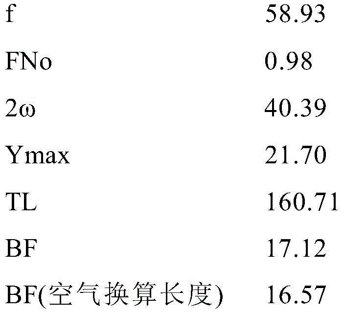
在以下的表2示出本实施例的光学系统的参数的值。Table 2 below shows the values of the parameters of the optical system of this embodiment.
(表2)第2实施例(Table 2) The second embodiment
[面数据][surface data]


[非球面数据][Aspherical data]
m:1m: 1
κ=0.0000K=0.0000
A4=-3.12694E-07,A6=-5.48964E-11,A8=-1.79711E-14,A4=-3.12694E-07, A6=-5.48964E-11, A8=-1.79711E-14,
A10=-1.73223E-18A10=-1.73223E-18
m:18m: 18
κ=0.0000K=0.0000
A4=-1.26938E-06,A6=-4.97145E-10,A8=2.93406E-13,A4=-1.26938E-06, A6=-4.97145E-10, A8=2.93406E-13,
A10=-1.78209E-16A10=-1.78209E-16
m:26m: 26
κ=0.0000K=0.0000
A4=2.60259E-06,A6=-6.63089E-09,A8=6.98584E-11,A4=2.60259E-06, A6=-6.63089E-09, A8=6.98584E-11,
A10=-2.75672E-13,A12=5.74140E-16,A14=-4.50780E-19A10=-2.75672E-13, A12=5.74140E-16, A14=-4.50780E-19
[各种数据][various data]
[可变间隔数据][variable interval data]

[透镜组数据][Lens group data]

[条件式对应值][Conditional corresponding value]
(1)fF/f=1.26(1) fF/f=1.26
(2)(r2L1+r1L1)/(r2L1-r1L1)=0.18(2) (r2L1+r1L1)/(r2L1-r1L1)=0.18
(3)(r2L2+r1L2)/(r2L2-r1L2)=0.22(3) (r2L2+r1L2)/(r2L2-r1L2)=0.22
(4)θgFLn+0.0021×νdLn=0.656(4) θgFLn+0.0021×νdLn=0.656
(4)θgFLn+0.0021×νdLn=0.657(4) θgFLn+0.0021×νdLn=0.657
(4)θgFLn+0.0021×νdLn=0.658(4) θgFLn+0.0021×νdLn=0.658
(4)θgFLn+0.0021×νdLn=0.660(4) θgFLn+0.0021×νdLn=0.660
(5)rc/bfa=3.20(5) rc/bfa=3.20
(6)rA/TLA=1.76(6) rA/TLA=1.76
(7)rB/TLB=2.48(7) rB/TLB=2.48
(8)f/fR=0.18(8) f/fR=0.18
(9)Pex=44.85(9)Pex=44.85
(10)-f1/f=8.56(10)-f1/f=8.56
(11)f2/f=1.21(11) f2/f=1.21
(12)2ω=40.39°(12)2ω=40.39°
(13)bfa/f=0.28(13) bfa/f=0.28
(14)FNo=0.98(14) FNo = 0.98
图4A和图4B分别是第2实施例的光学系统的无限远物体对焦时和近距离物体对焦时的各像差图。4A and 4B are aberration diagrams of the optical system of the second embodiment when focusing on an object at infinity and when focusing on a short-distance object, respectively.
通过各像差图可知,本实施例的光学系统从无限远物体对焦时到近距离物体对焦时良好地对各像差进行校正且具有优秀的成像性能。It can be seen from the various aberration diagrams that the optical system of this embodiment corrects various aberrations well and has excellent imaging performance from the time of focusing on an object at infinity to the time of focusing on a short-distance object.
(第3实施例)(third embodiment)
图5是第3实施例的光学系统的无限远物体对焦时的剖视图。Fig. 5 is a cross-sectional view of the optical system of the third embodiment when an object at infinity is in focus.
本实施例的光学系统从物体侧依次由具有正的光焦度的前组GF以及具有正的光焦度的后组GR构成。The optical system of this embodiment is composed of a front group GF having positive refractive power and a rear group GR having positive refractive power in order from the object side.
前组GF从物体侧依次由具有负的光焦度的第1透镜组G1以及具有正的光焦度的第2透镜组G2构成。The front group GF is composed of a first lens group G1 having negative refractive power and a second lens group G2 having positive refractive power in order from the object side.
第1透镜组G1从物体侧依次由将双凸形状的正透镜L11与双凹形状的负透镜L12接合而成的接合负透镜以及将双凹形状的负透镜L13与双凸形状的正透镜L14接合而成的接合正透镜构成。The first lens group G1 includes, in order from the object side, a cemented negative lens formed by joining a biconvex positive lens L11 and a biconcave negative lens L12, and a biconcave negative lens L13 and a biconvex positive lens L14. A cemented positive lens formed by bonding.
通过负透镜L12的像侧透镜面和负透镜L13的物体侧透镜面,形成双凸形状的空气透镜La1。A double-convex air lens La1 is formed by the image-side lens surface of the negative lens L12 and the object-side lens surface of the negative lens L13 .
第2透镜组G2从物体侧依次由凸面朝向物体侧的正弯月形透镜L21、双凸形状的正透镜L21、将双凸形状的正透镜L23与双凹形状的负透镜L24接合而成的接合负透镜、将双凸形状的正透镜L25与双凹形状的负透镜L26接合而成的接合正透镜、孔径光阑S、将双凹形状的负透镜L27与凸面朝向物体侧的正弯月形透镜L28接合而成的接合负透镜、双凸形状的正透镜L29、双凸形状的正透镜L210以及凸面朝向物体侧的负弯月形透镜L211构成。The second lens group G2 consists of a positive meniscus lens L21 with a convex surface facing the object side, a biconvex positive lens L21, a biconvex positive lens L23, and a biconcave negative lens L24 bonded in order from the object side. Condensed negative lens, cemented positive lens composed of biconvex positive lens L25 and biconcave negative lens L26, aperture stop S, biconcave negative lens L27 and positive meniscus with convex surface facing the object side A negative meniscus lens L28 is bonded, a biconvex positive lens L29, a biconvex positive lens L210, and a negative meniscus lens L211 with a convex surface facing the object side.
通过负透镜L26的像侧透镜面和负透镜L27的物体侧透镜面,形成包含孔径光阑S的双凸形状的空气透镜La2。A biconvex air lens La2 including an aperture stop S is formed by the image-side lens surface of the negative lens L26 and the object-side lens surface of the negative lens L27 .
后组GR从物体侧依次由将双凸形状的正透镜L31与双凹形状的负透镜L32接合而成的接合正透镜以及将双凸形状的正透镜L33与双凹形状的负透镜L34接合而成的接合正透镜构成。The rear group GR consists of a cemented positive lens in which a biconvex positive lens L31 and a biconcave negative lens L32 are cemented, and a biconvex positive lens L33 and a biconcave negative lens L34 in order from the object side. It is composed of a bonded positive lens.
在后组GR与像面I之间,配置有由低通滤光片等构成的滤光片组FL。Between the rear group GR and the image plane I, a filter group FL composed of low-pass filters and the like is disposed.
在像面I上配置有由CCD或CMOS等构成的拍摄元件(省略图示)。On the image plane I, an imaging element (not shown) made of a CCD, CMOS, or the like is arranged.
在本实施例的光学系统中,通过使前组GF沿着光轴向物体侧移动来进行从无限远物体向近距离物体的对焦。In the optical system of this embodiment, focusing from an object at infinity to a short-distance object is performed by moving the front group GF toward the object side along the optical axis.
在以下的表3示出本实施例的光学系统的参数的值。Table 3 below shows the values of the parameters of the optical system of this embodiment.
(表3)第3实施例(Table 3) The third embodiment
[面数据][surface data]


[非球面数据][Aspherical data]
m:1m: 1
κ=0.0000K=0.0000
A4=-4.46166E-07,A6=-5.12059E-11,A8=-5.73749E-16,A4=-4.46166E-07, A6=-5.12059E-11, A8=-5.73749E-16,
A10=-7.59667E-19A10=-7.59667E-19
m:23m: 23
κ=0.0000K=0.0000
A4=-6.70053E-07,A6=-1.40564E-10,A8=-2.88155E-14,A4=-6.70053E-07, A6=-1.40564E-10, A8=-2.88155E-14,
A10=5.19675E-17A10=5.19675E-17
m:32m: 32
κ=0.0000K=0.0000
A4=2.53486E-06,A6=-6.25069E-09,A8=5.60707E-11,A4=2.53486E-06, A6=-6.25069E-09, A8=5.60707E-11,
A10=-1.82993E-13,A12=3.28690E-16,A14=-2.06450E-19A10=-1.82993E-13, A12=3.28690E-16, A14=-2.06450E-19
[各种数据][various data]


[可变间隔数据][variable interval data]

[透镜组数据][Lens group data]

[条件式对应值][Conditional corresponding value]
(1)fF/f=1.39(1) fF/f=1.39
(2)(r2L1+r1L1)/(r2L1-r1L1)=0.03(2) (r2L1+r1L1)/(r2L1-r1L1)=0.03
(3)(r2L2+r1L2)/(r2L2-r1L2)=-0.68(3) (r2L2+r1L2)/(r2L2-r1L2)=-0.68
(4)θgFLn+0.0021×νdLn=0.656(4) θgFLn+0.0021×νdLn=0.656
(4)θgFLn+0.0021×νdLn=0.657(4) θgFLn+0.0021×νdLn=0.657
(5)rc/bfa=3.10(5) rc/bfa=3.10
(6)rA/TLA=1.47(6) rA/TLA=1.47
(7)rB/TLB=1.71(7) rB/TLB=1.71
(8)f/fR=0.23(8) f/fR=0.23
(9)Pex=40.21(9)Pex=40.21
(10)-f1/f=9.05(10)-f1/f=9.05
(11)f2/f=1.51(11) f2/f=1.51
(12)2ω=42.76°(12)2ω=42.76°
(13)bfa/f=0.27(13) bfa/f=0.27
(14)FNo=0.87(14) FNo = 0.87
图6A和图6B分别是第3实施例的光学系统的无限远物体对焦时和近距离物体对焦时的各像差图。6A and 6B are aberration diagrams of the optical system of the third embodiment when focusing on an object at infinity and when focusing on a short-distance object, respectively.
通过各像差图可知,本实施例的光学系统从无限远物体对焦时到近距离物体对焦时良好地对各像差进行校正且具有优秀的成像性能。It can be seen from the various aberration diagrams that the optical system of this embodiment corrects various aberrations well and has excellent imaging performance from the time of focusing on an object at infinity to the time of focusing on a short-distance object.
(第4实施例)(fourth embodiment)
图7是第4实施例的光学系统的无限远物体对焦时的剖视图。Fig. 7 is a cross-sectional view of the optical system of the fourth embodiment when an object at infinity is in focus.
本实施例的光学系统从物体侧依次由具有正的光焦度的前组GF以及具有正的光焦度的后组GR构成。The optical system of this embodiment is composed of a front group GF having positive refractive power and a rear group GR having positive refractive power in order from the object side.
前组GF从物体侧依次由具有负的光焦度的第1透镜组G1以及具有正的光焦度的第2透镜组G2构成。The front group GF is composed of a first lens group G1 having negative refractive power and a second lens group G2 having positive refractive power in order from the object side.
第1透镜组G1从物体侧依次由凸面朝向物体侧的负弯月形透镜L11以及将双凸形状的正透镜L12与双凹形状的负透镜L13接合而成的接合正透镜构成。The first lens group G1 is composed of a negative meniscus lens L11 with a convex surface facing the object side and a bonded positive lens formed by bonding a biconvex positive lens L12 and a biconcave negative lens L13 in order from the object side.
第2透镜组G2从物体侧依次由双凸形状的正透镜L21、双凸形状的正透镜L22、将双凹形状的负透镜L23与凸面朝向物体侧的正弯月形透镜L24接合而成的接合负透镜、孔径光阑S、将双凹形状的负透镜L25与双凸形状的正透镜L26接合而成的接合正透镜、凸面朝向物体侧的正弯月形透镜L27以及将双凸形状的正透镜L28与双凹形状的负透镜L29接合而成的接合负透镜构成。The second lens group G2 is composed of a biconvex positive lens L21, a biconvex positive lens L22, a biconcave negative lens L23, and a positive meniscus lens L24 whose convex surface faces the object side in order from the object side. A cemented negative lens, an aperture stop S, a cemented positive lens formed by cementing a biconcave negative lens L25 and a biconvex positive lens L26, a positive meniscus lens L27 with a convex surface facing the object side, and a biconvex positive lens L27. The positive lens L28 and the biconcave negative lens L29 are cemented to constitute a cemented negative lens.
通过第1透镜组G1的负透镜L13的像侧透镜面和第2透镜组G2的正透镜L21的物体侧透镜面,形成凸面朝向物体侧的空气透镜La1。An air lens La1 with a convex surface facing the object side is formed by the image-side lens surface of the negative lens L13 of the first lens group G1 and the object-side lens surface of the positive lens L21 of the second lens group G2.
通过第2透镜组G2的正弯月形透镜L24的像侧透镜面和负透镜L25的物体侧透镜面,形成包含孔径光阑S的双凸形状的空气透镜La2。The image-side lens surface of the positive meniscus lens L24 of the second lens group G2 and the object-side lens surface of the negative lens L25 form a biconvex air lens La2 including an aperture stop S.
后组GR从物体侧依次由将双凸形状的正透镜L31与双凹形状的负透镜L32接合而成的接合正透镜以及凸面朝向物体侧的正弯月形透镜L33构成。The rear group GR includes, in order from the object side, a cemented positive lens formed by joining a biconvex positive lens L31 and a biconcave negative lens L32 , and a positive meniscus lens L33 with a convex surface facing the object side.
在后组GR与像面I之间,配置有由低通滤光片等构成的滤光片组FL。Between the rear group GR and the image plane I, a filter group FL composed of low-pass filters and the like is disposed.
在像面I上配置有由CCD或CMOS等构成的拍摄元件(省略图示)。On the image plane I, an imaging element (not shown) made of a CCD, CMOS, or the like is arranged.
在本实施例的光学系统中,通过使前组GF沿着光轴向物体侧移动来进行从无限远物体向近距离物体的对焦。In the optical system of this embodiment, focusing from an object at infinity to a short-distance object is performed by moving the front group GF toward the object side along the optical axis.
在以下的表4示出本实施例的光学系统的参数的值。Table 4 below shows the values of the parameters of the optical system of this embodiment.
(表4)第4实施例(Table 4) The fourth embodiment
[面数据][surface data]


[非球面数据][Aspherical data]
m:2m: 2
κ=0.0000K=0.0000
A4=1.16114E-06,A6=2.95643E-10,A8=-6.37189E-14,A4=1.16114E-06, A6=2.95643E-10, A8=-6.37189E-14,
A10=1.41668E-16A10=1.41668E-16
m:17m: 17
κ=0.0000K=0.0000
A4=-6.16353E-07,A6=-4.48845E-11,A8=-3.85019E-13,A4=-6.16353E-07, A6=-4.48845E-11, A8=-3.85019E-13,
A10=2.55435E-16A10=2.55435E-16
m:26m: 26
κ=0.0000K=0.0000
A4=3.59886E-06,A6=-1.74814E-08,A8=1.46565E-10,A4=3.59886E-06, A6=-1.74814E-08, A8=1.46565E-10,
A10=-5.81529E-13,A12=1.21940E-15,A14=-1.02110E-18A10=-5.81529E-13, A12=1.21940E-15, A14=-1.02110E-18
[各种数据][various data]

[可变间隔数据][variable interval data]

[透镜组数据][Lens group data]

[条件式对应值][Conditional corresponding value]
(1)fF/f=1.37(1) fF/f=1.37
(2)(r2L1+r1L1)/(r2L1-r1L1)=2.15(2) (r2L1+r1L1)/(r2L1-r1L1)=2.15
(3)(r2L2+r1L2)/(r2L2-r1L2)=-0.74(3) (r2L2+r1L2)/(r2L2-r1L2)=-0.74
(4)θgFLn+0.0021×νdLn=0.657(4) θgFLn+0.0021×νdLn=0.657
(5)rc/bfa=2.87(5) rc/bfa=2.87
(6)rA/TLA=1.12(6) rA/TLA=1.12
(7)rB/TLB=1.51(7) rB/TLB=1.51
(8)f/fR=0.24(8) f/fR=0.24
(9)Pex=40.00(9)Pex=40.00
(10)-f1/f=6.54(10)-f1/f=6.54
(11)f2/f=1.23(11) f2/f=1.23
(12)2ω=46.48°(12) 2ω=46.48°
(13)bfa/f=0.33(13)bfa/f=0.33
(14)FNo=0.98(14) FNo = 0.98
图8A和图8B分别是第4实施例的光学系统的无限远物体对焦时和近距离物体对焦时的各像差图。8A and 8B are aberration diagrams of the optical system of the fourth embodiment when focusing on an object at infinity and when focusing on a short-distance object, respectively.
通过各像差图可知,本实施例的光学系统从无限远物体对焦时到近距离物体对焦时良好地对各像差进行校正且具有优秀的成像性能。It can be seen from the various aberration diagrams that the optical system of this embodiment corrects various aberrations well and has excellent imaging performance from the time of focusing on an object at infinity to the time of focusing on a short-distance object.
根据上述各实施例,能够实现具有能够良好地对各像差进行校正的良好的光学性能、且适合使用于高像素化的拍摄元件的光学系统。According to each of the above-described embodiments, it is possible to realize an optical system that has good optical performance capable of correcting various aberrations well, and is suitable for use in a high-pixel imaging device.
另外,上述各实施例示出本申请发明的一具体例,本申请发明并不限定于此。能够在不损坏本实施方式的光学系统的光学性能的范围内适当采用以下的内容。In addition, each of the above-mentioned embodiments shows a specific example of the invention of the present application, and the invention of the present application is not limited thereto. The following matters can be suitably adopted within the range not to impair the optical performance of the optical system of the present embodiment.
虽然作为本实施方式的光学系统的数值实施例示出了2组结构,但是本实施方式并不限定于此,还能够构成其他组结构(例如,3组等)的光学系统。具体地讲,也可以是在上述各实施例的光学系统的最靠物体侧或最靠像侧增加透镜或透镜组的结构。或者,也可以在相邻的透镜组与透镜组之间增加透镜或透镜组。另外,虽然示出了前组为2组结构,但是本申请并不限定于此,还可以成为其他组结构(例如,3组等)。具体地讲,也可以是在上述各实施例的前组的最靠物体侧或最像侧、第1透镜组与第2透镜组之间增加透镜或透镜组的结构。另外,也可以是在上述各实施例的后组的物体侧或像侧增加透镜或透镜组的结构。Although the numerical example of the optical system of this embodiment shows a 2-group structure, this embodiment is not limited thereto, and an optical system with other group structures (for example, 3 groups, etc.) can also be configured. Specifically, it is also possible to add a lens or a lens group to the most object side or the most image side of the optical system of the above-mentioned embodiments. Alternatively, lenses or lens groups may also be added between adjacent lens groups. In addition, although it was shown that the front group has a two-group structure, the present application is not limited thereto, and other group structures (for example, three groups, etc.) are also possible. Specifically, a structure in which lenses or lens groups are added between the first lens group and the second lens group on the most object side or the most image side of the front group in the above embodiments. In addition, it is also possible to add a lens or a lens group to the object side or image side of the rear group in the above-mentioned embodiments.
另外,在上述各实施例中,使前组为对焦透镜组。该对焦透镜组还能够应用于自动对焦,也适合于自动对焦用的电机,例如超声波电机、步进电机、VCM电机等的驱动。In addition, in each of the above-mentioned embodiments, the front group is a focusing lens group. The focus lens group can also be applied to autofocus, and is also suitable for driving motors for autofocus, such as ultrasonic motors, stepping motors, and VCM motors.
另外,在上述各实施例的光学系统中,也可以是通过使任意一个透镜组整体或其一部分作为防抖组以包含对于光轴垂直方向的分量的方式移动、或者向包含光轴的面内方向旋转移动(摆动)来进行防抖的结构。In addition, in the optical system of each of the above-mentioned embodiments, it is also possible to move any lens group as a whole or a part of it as an anti-shake group to include a component perpendicular to the optical axis, or to move in a plane including the optical axis. A structure that performs anti-shake by rotating and moving (swinging) in the direction.
另外,关于上述各实施例的光学系统的孔径光阑,也可以是不设置作为孔径光阑的部件而用透镜框来代替其作用的结构。In addition, regarding the aperture stop of the optical system of each of the above-mentioned embodiments, a member as the aperture stop may not be provided, and a lens frame may be used instead of its function.
另外,构成上述各实施例的光学系统的透镜的透镜面可以是球面或平面,或者也可以是非球面。在透镜面为球面或平面时,透镜加工和组装调整变得容易,能够防止由透镜加工和组装调整的误差引起的光学性能的劣化,因此是优选的。另外,即使在像面偏移的情况下,描绘性能的劣化也少,因此是优选的。在透镜面为非球面时,可以是基于研磨加工的非球面、通过模具将玻璃成型为非球面形状的玻璃模铸非球面、或将设置在玻璃表面的树脂形成为非球面形状的复合型非球面中的任意一个。另外,透镜面也可以是衍射面,也可以是使透镜为折射率分布型透镜(GRIN透镜)或者塑料透镜。In addition, the lens surfaces of the lenses constituting the optical systems of the above-described embodiments may be spherical, flat, or aspherical. When the lens surface is a spherical surface or a flat surface, lens processing and assembly adjustment become easy, and deterioration of optical performance due to errors in lens processing and assembly adjustment can be prevented, which is preferable. In addition, even when the image plane is shifted, there is little deterioration in drawing performance, which is preferable. When the lens surface is an aspheric surface, it can be an aspheric surface based on grinding, a glass molded aspheric surface in which glass is molded into an aspherical shape by a mold, or a composite aspheric surface in which a resin placed on the glass surface is formed into an aspherical shape. any one of the spheres. In addition, the lens surface may be a diffractive surface, or the lens may be a distributed refractive index lens (GRIN lens) or a plastic lens.
另外,也可以在构成上述各实施例的光学系统的透镜的透镜面施加在宽波长区域中具有高透射率的增透膜。由此,能够减轻眩光和重影并实现高对比度的高光学性能。In addition, an anti-reflection coating having a high transmittance in a wide wavelength region may be applied to the lens surface of the lens constituting the optical system of each of the above-described embodiments. Thus, it is possible to reduce flare and ghosting and achieve high optical performance with high contrast.
接着,根据图9对具备本实施方式的光学系统的相机进行说明。Next, a camera including the optical system of this embodiment will be described based on FIG. 9 .
图9是示出具备本实施方式的光学系统的相机结构的图。FIG. 9 is a diagram showing the configuration of a camera including the optical system of the present embodiment.
如图9所示,相机1是具备上述第1实施例的光学系统来作为摄影镜头2的镜头可换式的无反光镜相机。As shown in FIG. 9 , the
在该相机1中,来自未图示的物体(被摄体)的光通过摄影镜头2被聚光,并且通过未图示的OLPF(Optical low pass filter:光学低通滤光片)在拍摄部3的拍摄面上形成被摄体像。并且,被摄体像通过设置在拍摄部3的光电转换元件被光电转换而生成被摄体的图像。该图像显示于设置在相机1的EVF(Electronic view finder:电子取景器)4。由此,摄影者能够通过EVF4对被摄体进行观察。In this
另外,当由摄影者按压未图示的释放按钮时,通过拍摄部3生成的被摄体的图像存储在未图示的存储器。由此,摄影者能够进行基于该相机1的被摄体的摄影。In addition, when the photographer presses a release button not shown, an image of the subject generated by the
此处,作为摄影镜头2搭载于该相机1的上述第1实施例的光学系统,具有能够如上所述良好地对各像差进行校正的良好的光学性能,适合使用于高像素化的拍摄元件。即,该相机1适合于高像素化的拍摄元件,能够实现高光学性能。另外,即使构成搭载上述第2~第4实施例的光学系统来作为摄影镜头2的相机,也能够起到与上述相机1相同的效果。另外,即使在具有快速复原反光镜且通过取景器光学系统来对被摄体进行观察的单反类型相机上搭载了上述各实施例的光学系统的情况下,也能够起到与上述相机1相同的效果。Here, the optical system of the above-mentioned first embodiment, which is mounted on the
接着,根据图10对本实施方式的光学系统的制造方法的概略进行说明。Next, the outline of the manufacturing method of the optical system of this embodiment is demonstrated based on FIG. 10. FIG.
图10是示出本实施方式的光学系统的制造方法的概略的流程图。FIG. 10 is a flowchart illustrating an outline of a method of manufacturing an optical system according to this embodiment.
在图10所示的本实施方式的光学系统的制造方法中,该光学系统从物体侧依次由前组和后组构成,所述前组具有正的光焦度,包含以下的步骤S1~S3。In the manufacturing method of the optical system of the present embodiment shown in FIG. 10 , the optical system is sequentially composed of a front group and a rear group from the object side, the front group has positive refractive power, and includes the following steps S1 to S3 .
步骤S1:准备前组和后组,在镜筒内从物体侧依次配置。Step S1: Prepare the front group and the rear group, and arrange them sequentially from the object side in the lens barrel.
步骤S2:以在进行对焦时所述前组沿着光轴移动的方式构成。Step S2: Construct in such a way that the front group moves along the optical axis when focusing.
步骤S3:使得光学系统满足以下的条件式(1)。Step S3: Make the optical system satisfy the following conditional expression (1).
(1)0.90<fF/f<1.50(1) 0.90<fF/f<1.50
其中,in,
fF:所述前组的焦距fF: focal length of the front group
f:所述光学系统的整个系统的焦距f: focal length of the entire system of the optical system
根据该本实施方式的光学系统的制造方法,能够制造如下的光学系统:具有能够良好地对各像差进行校正的良好的光学性能,适合使用于高像素化的拍摄元件。According to the manufacturing method of the optical system of this embodiment, it is possible to manufacture an optical system having good optical performance capable of correcting various aberrations well, and suitable for use in a high-pixel imaging element.
标号说明Label description
GF 前组 GR 后组GF front group GR rear group
G1 第1透镜组 G2 第2透镜组G1 1st lens group G2 2nd lens group
S 孔径光阑 I 像面S Aperture stop I Image plane
1 相机 2 摄影镜头1
Claims (19)
Applications Claiming Priority (1)
| Application Number | Priority Date | Filing Date | Title |
|---|---|---|---|
| PCT/JP2018/020552 WO2019229849A1 (en) | 2018-05-29 | 2018-05-29 | Optical system, optical device, and method for manufacturing optical system |
Publications (2)
| Publication Number | Publication Date |
|---|---|
| CN112166360A CN112166360A (en) | 2021-01-01 |
| CN112166360B true CN112166360B (en) | 2022-12-16 |
Family
ID=68697458
Family Applications (1)
| Application Number | Title | Priority Date | Filing Date |
|---|---|---|---|
| CN201880093788.1A Active CN112166360B (en) | 2018-05-29 | 2018-05-29 | Optical system and optical equipment |
Country Status (4)
| Country | Link |
|---|---|
| US (1) | US12025779B2 (en) |
| JP (1) | JP7143882B2 (en) |
| CN (1) | CN112166360B (en) |
| WO (1) | WO2019229849A1 (en) |
Families Citing this family (2)
| Publication number | Priority date | Publication date | Assignee | Title |
|---|---|---|---|---|
| JP2023163074A (en) * | 2022-04-27 | 2023-11-09 | キヤノン株式会社 | Optical system and imaging device |
| CN116149014B (en) * | 2022-12-19 | 2024-05-03 | 福建福光股份有限公司 | High-resolution large-image-plane optical imaging system |
Family Cites Families (15)
| Publication number | Priority date | Publication date | Assignee | Title |
|---|---|---|---|---|
| JPS61238010A (en) * | 1985-04-15 | 1986-10-23 | Asahi Optical Co Ltd | Semitelephoto microlens |
| JPH03141313A (en) | 1989-10-27 | 1991-06-17 | Canon Inc | shooting lens |
| JPH11211978A (en) | 1998-01-20 | 1999-08-06 | Canon Inc | Retro focus lens |
| JP3698134B2 (en) | 2002-08-30 | 2005-09-21 | 株式会社ニコン | Zoom lens |
| JP2008309998A (en) | 2007-06-14 | 2008-12-25 | Sony Corp | Tilt lens system and imaging device |
| JP5396658B2 (en) | 2008-07-29 | 2014-01-22 | 株式会社タムロン | Large aperture ratio lens |
| CN101819315B (en) | 2009-02-27 | 2014-05-07 | 柯尼卡美能达精密光学株式会社 | Image pickup lens, image pickup apparatus, and mobile terminal |
| JP2012203234A (en) | 2011-03-25 | 2012-10-22 | Konica Minolta Advanced Layers Inc | Imaging optical system, imaging apparatus and digital instrument |
| CN104541192B (en) * | 2012-08-21 | 2017-05-17 | 富士胶片株式会社 | Camera lens and camera device |
| JP2014092681A (en) | 2012-11-02 | 2014-05-19 | Tamron Co Ltd | Image capturing lens |
| JP2015004717A (en) | 2013-06-19 | 2015-01-08 | リコーイメージング株式会社 | Single focus lens system |
| JP6266497B2 (en) | 2014-11-25 | 2018-01-24 | 富士フイルム株式会社 | Imaging lens and imaging apparatus |
| WO2016121945A1 (en) | 2015-01-30 | 2016-08-04 | 株式会社ニコン | Variable power optical system, optical device, and method for producing variable power optical system |
| JP6516579B2 (en) | 2015-06-17 | 2019-05-22 | キヤノン株式会社 | Image pickup optical system and image pickup apparatus having the same |
| JP6849350B2 (en) | 2016-09-05 | 2021-03-24 | キヤノン株式会社 | Optical system and optical equipment with it |
-
2018
- 2018-05-29 CN CN201880093788.1A patent/CN112166360B/en active Active
- 2018-05-29 JP JP2020522432A patent/JP7143882B2/en active Active
- 2018-05-29 WO PCT/JP2018/020552 patent/WO2019229849A1/en not_active Ceased
- 2018-05-29 US US17/059,466 patent/US12025779B2/en active Active
Also Published As
| Publication number | Publication date |
|---|---|
| JPWO2019229849A1 (en) | 2021-05-13 |
| JP7143882B2 (en) | 2022-09-29 |
| US12025779B2 (en) | 2024-07-02 |
| US20210208373A1 (en) | 2021-07-08 |
| WO2019229849A1 (en) | 2019-12-05 |
| CN112166360A (en) | 2021-01-01 |
Similar Documents
| Publication | Publication Date | Title |
|---|---|---|
| US12169323B2 (en) | Zoom lens, optical apparatus, and method for manufacturing zoom lens | |
| CN107621690B (en) | Zoom optical system | |
| CN102132189B (en) | Zoom lens, imaging device, and method of manufacturing zoom lens | |
| CN102346294B (en) | Zoom lens system, optical device and method for manufacturing zoom lens system | |
| CN110832376A (en) | Variable magnification optical system, optical device, and method for manufacturing variable magnification optical system | |
| CN111492287B (en) | Optical system and optical apparatus | |
| CN112368624B (en) | Variable magnification optical system, optical device and manufacturing method of variable magnification optical system | |
| CN103477265B (en) | Zoom lens, imaging device and the method for the manufacture of zoom lens | |
| JP7627444B2 (en) | Optical systems and optical instruments | |
| JP5434447B2 (en) | Wide-angle lens and optical equipment | |
| JP2023171585A (en) | Variable magnification optical system, optical equipment, and manufacturing method of variable magnification optical system | |
| CN107850762A (en) | Variable power optical system, optical device, manufacturing method of variable power optical system | |
| JP5423299B2 (en) | Wide-angle lens and optical equipment | |
| CN112166360B (en) | Optical system and optical equipment | |
| CN113348397B (en) | Variable magnification optical system and optical apparatus | |
| CN107209350B (en) | Zoom optical system and optical device | |
| CN104769477B (en) | The production method of variable magnification optical system, Optical devices and variable magnification optical system | |
| JP2025052870A (en) | Optical system, optical device, and method for manufacturing optical system | |
| CN104919354B (en) | Variable magnification optical system, optical device, and production method for variable magnification optical system | |
| CN104755983B (en) | Variable power optical system, optical device and method for manufacturing variable power optical system | |
| CN104755986B (en) | Variable magnification optical system, optical device, and production method for variable magnification optical system | |
| JP5267956B2 (en) | Zoom lens, imaging apparatus, and zoom lens manufacturing method |
Legal Events
| Date | Code | Title | Description |
|---|---|---|---|
| PB01 | Publication | ||
| PB01 | Publication | ||
| SE01 | Entry into force of request for substantive examination | ||
| SE01 | Entry into force of request for substantive examination | ||
| GR01 | Patent grant | ||
| GR01 | Patent grant |