CN112166329B - supersonic airspeed indicator - Google Patents
supersonic airspeed indicator Download PDFInfo
- Publication number
- CN112166329B CN112166329B CN201980027132.4A CN201980027132A CN112166329B CN 112166329 B CN112166329 B CN 112166329B CN 201980027132 A CN201980027132 A CN 201980027132A CN 112166329 B CN112166329 B CN 112166329B
- Authority
- CN
- China
- Prior art keywords
- acoustic
- acoustic signal
- electronic device
- fluid
- electro
- Prior art date
- Legal status (The legal status is an assumption and is not a legal conclusion. Google has not performed a legal analysis and makes no representation as to the accuracy of the status listed.)
- Active
Links
Images


Classifications
-
- G—PHYSICS
- G01—MEASURING; TESTING
- G01P—MEASURING LINEAR OR ANGULAR SPEED, ACCELERATION, DECELERATION, OR SHOCK; INDICATING PRESENCE, ABSENCE, OR DIRECTION, OF MOVEMENT
- G01P5/00—Measuring speed of fluids, e.g. of air stream; Measuring speed of bodies relative to fluids, e.g. of ship, of aircraft
- G01P5/24—Measuring speed of fluids, e.g. of air stream; Measuring speed of bodies relative to fluids, e.g. of ship, of aircraft by measuring the direct influence of the streaming fluid on the properties of a detecting acoustical wave
- G01P5/245—Measuring speed of fluids, e.g. of air stream; Measuring speed of bodies relative to fluids, e.g. of ship, of aircraft by measuring the direct influence of the streaming fluid on the properties of a detecting acoustical wave by measuring transit time of acoustical waves
-
- G—PHYSICS
- G01—MEASURING; TESTING
- G01F—MEASURING VOLUME, VOLUME FLOW, MASS FLOW OR LIQUID LEVEL; METERING BY VOLUME
- G01F1/00—Measuring the volume flow or mass flow of fluid or fluent solid material wherein the fluid passes through a meter in a continuous flow
- G01F1/66—Measuring the volume flow or mass flow of fluid or fluent solid material wherein the fluid passes through a meter in a continuous flow by measuring frequency, phase shift or propagation time of electromagnetic or other waves, e.g. using ultrasonic flowmeters
- G01F1/667—Arrangements of transducers for ultrasonic flowmeters; Circuits for operating ultrasonic flowmeters
-
- G—PHYSICS
- G01—MEASURING; TESTING
- G01P—MEASURING LINEAR OR ANGULAR SPEED, ACCELERATION, DECELERATION, OR SHOCK; INDICATING PRESENCE, ABSENCE, OR DIRECTION, OF MOVEMENT
- G01P5/00—Measuring speed of fluids, e.g. of air stream; Measuring speed of bodies relative to fluids, e.g. of ship, of aircraft
- G01P5/24—Measuring speed of fluids, e.g. of air stream; Measuring speed of bodies relative to fluids, e.g. of ship, of aircraft by measuring the direct influence of the streaming fluid on the properties of a detecting acoustical wave
- G01P5/241—Measuring speed of fluids, e.g. of air stream; Measuring speed of bodies relative to fluids, e.g. of ship, of aircraft by measuring the direct influence of the streaming fluid on the properties of a detecting acoustical wave by using reflection of acoustical waves, i.e. Doppler-effect
-
- B—PERFORMING OPERATIONS; TRANSPORTING
- B64—AIRCRAFT; AVIATION; COSMONAUTICS
- B64D—EQUIPMENT FOR FITTING IN OR TO AIRCRAFT; FLIGHT SUITS; PARACHUTES; ARRANGEMENT OR MOUNTING OF POWER PLANTS OR PROPULSION TRANSMISSIONS IN AIRCRAFT
- B64D43/00—Arrangements or adaptations of instruments
- B64D43/02—Arrangements or adaptations of instruments for indicating aircraft speed or stalling conditions
Landscapes
- Physics & Mathematics (AREA)
- Engineering & Computer Science (AREA)
- General Physics & Mathematics (AREA)
- Acoustics & Sound (AREA)
- Multimedia (AREA)
- Aviation & Aerospace Engineering (AREA)
- Electromagnetism (AREA)
- Fluid Mechanics (AREA)
- Measuring Volume Flow (AREA)
- Investigating Or Analyzing Materials By The Use Of Ultrasonic Waves (AREA)
Abstract
本发明涉及用于测量流体的流速的电子装置,包括:至少两个电声换能器,适于发射声信号穿过流动流体和/或穿过流动流体接收声信号,该电子装置适于根据发射的声信号的特性以及接收到的一个或多个声信号的特性来确定流体的流速的测量值,这些所接收的声信号与所发射的声信号的反射相对应。

The present invention relates to an electronic device for measuring the flow velocity of a fluid, comprising: at least two electro-acoustic transducers adapted to transmit acoustic signals through a flowing fluid and/or to receive acoustic signals through a flowing fluid, the electronic device being adapted according to A measure of the flow velocity of the fluid is determined from a characteristic of the transmitted acoustic signal and a characteristic of the one or more received acoustic signals corresponding to reflections of the transmitted acoustic signal.
Description
本发明涉及计量领域。更具体地,本发明涉及有利地适于航空领域的空速指示器。The present invention relates to the field of metrology. More specifically, the invention relates to an airspeed indicator advantageously adapted to the field of aviation.
在航空领域中,使用被称为皮托管或普朗特尔天线的空速指示器是公知的。In the field of aviation, it is known to use airspeed indicators known as Pitot tube or Prandel antennas.
在图1中示出了这种空速指示器100,在下文中称为皮托管。皮托管的工作原理是例如借助于差压计103来测量所谓的静压力Ps和所谓的总压力Pt之间的压力差。静压力Ps是通过管连接到位于皮托管100的主体中的进气口101A的腔室101B的压力。进气口101A布置为垂直于流体的流动方向,即,图1中的由左至右的箭头所表示的流动方向。该静压力Ps不会根据待测流体的流速而变化。总压力Pt是通过管连接到位于皮托管100的主体中的进气口102A的腔室102B中的压力。进气口102A布置为面对流体的流动方向。总压力Pt是静态压力Ps和所谓的动态压力之和。动态压力是由流体的流动引起的压力。因此,总压力Pt和静压力Ps之间的差仅是取决于流体的流速的动态压力。通常将皮托管100固定在飞机的机身104上适于飞机的运动方向的位置,以便确定飞机周围的空气的流速,所述速度通常称为相对风。对于飞机而言,了解该相对风速是至关重要的,飞机的上升是由机翼产生的空气动力、升力提供的。这是因为,在低于一定速度(称为失速速度)时,飞机发生升力损失,这可能会导致事故。Such an
如果进气口101A或102A中的一个或另一个被阻塞,皮托管将无法再正常工作。因此,水的存在、冰的形成或与异物(例如,昆虫或鸟类)的碰撞可能会阻塞进气口之一。然后皮托管将给出错误的相对风测量结果,而不会指示测量结果是错误的。例如,进气口102A的阻塞将给出错误的测量结果,指示当飞机仅增加高度时得以增大的相对风速。在恶劣的天气条件下,特别是在能见度低的情况下,飞行员可能无法察觉到皮托管所提供的相对风测量值是不一致的,这有可能导致潜在危险情况。If one or the other of the
因此,有必要提出提供对流体的流速进行可靠测量的解决方案。Therefore, there is a need for a solution that provides a reliable measurement of the flow rate of the fluid.
本发明涉及用于测量流体的流速的电子装置,该电子装置包括:The present invention relates to an electronic device for measuring the flow rate of a fluid, the electronic device comprising:
第一电声换能器,适于在第一中心轴上发射和/或接收声信号,a first electroacoustic transducer adapted to transmit and/or receive acoustic signals on a first central axis,
第二电声换能器,适于在第二中心轴上发射和/或接收声信号,该第一中心轴和该第二中心轴唯一地限定与待测量的流体的流动方向平行的平面,a second electroacoustic transducer adapted to transmit and/or receive acoustic signals on a second central axis, the first central axis and the second central axis uniquely defining a plane parallel to the flow direction of the fluid to be measured,
适于反射声信号的表面,该表面布置在第一中心轴和第二中心轴的交点处,每个轴与穿过该交点正交于该表面的直线形成相同的角度。每个电声换能器位于距离表面相同的距离处,A surface adapted to reflect acoustic signals, the surface being arranged at the intersection of the first central axis and the second central axis, each axis forming the same angle with a line passing through the intersection and normal to the surface. Each electro-acoustic transducer is located at the same distance from the surface,
控制电声换能器的模块,A module to control the electro-acoustic transducer,
电子装置适于允许流体在表面与两个电声换能器之间自由流动,以及the electronics are adapted to allow free flow of fluid between the surface and the two electro-acoustic transducers, and
电子装置适于:The electronic device is suitable for:
经由第一电声换能器发射第一声信号,transmitting a first acoustic signal via a first electroacoustic transducer,
经由第一或第二电声换能器接收与第一声信号的一个或多个反射相对应的第二声信号,receiving a second acoustic signal corresponding to one or more reflections of the first acoustic signal via the first or second electroacoustic transducer,
根据所发射的第一声信号和所接收的第二声信号的距离(h)和角度(θ),确定流体的流速。From the distance (h) and angle (θ) of the transmitted first acoustic signal and the received second acoustic signal, the flow velocity of the fluid is determined.
根据本发明的补充实施方式,每个电声换能器是在250kHz至650kHz的频率范围内操作的非接触超声传感器。According to a complementary embodiment of the invention, each electroacoustic transducer is a non-contact ultrasonic sensor operating in the frequency range of 250 kHz to 650 kHz.
根据本发明的补充实施方式,该电子装置适于:According to a supplementary embodiment of the invention, the electronic device is adapted to:
经由表面上的反射来确定第一电声换能器与第二电声换能器之间的声信号的第一所谓的向外行进时间(T+),determining a first so-called outward travel time (T + ) of the acoustic signal between the first electroacoustic transducer and the second electroacoustic transducer via reflection on the surface,
经由表面上的反射来确定第二电声换能器与第一电声换能器之间的声信号的第二所谓的返回行进时间(T-),determining a second so-called return travel time (T − ) of the acoustic signal between the second electroacoustic transducer and the first electroacoustic transducer via reflection on the surface,
根据以下公式确定流体的流速(V):Determine the flow velocity (V) of the fluid according to the following formula:

根据本发明的补充实施方式,该电子装置适于根据以下公式确定流体中的声音的运动速度(C):According to a complementary embodiment of the invention, the electronic device is adapted to determine the speed of motion (C) of sound in the fluid according to the following formula:

根据本发明的补充实施方式,电子装置包括:垂直于流体的流动方向布置的第三电声换能器,该电子装置适于借助于该第三电声换能器确定流体中的声音的运动速度(C)。According to a supplementary embodiment of the invention, the electronic device comprises a third electroacoustic transducer arranged perpendicular to the flow direction of the fluid, the electronic device being adapted to determine the movement of sound in the fluid by means of the third electroacoustic transducer speed (C).
根据本发明的补充实施方式,所发射的第一声信号是与第一频率(fe)相关联的具有高斯包络的单频谐波声信号,与反射的第一声信号相对应的第二声信号被第二电声换能器接收,并与第二频率(fd)相关联,所述电子装置适于根据以下公式确定流体的流速(V):According to a complementary embodiment of the invention, the emitted first acoustic signal is a single-frequency harmonic acoustic signal with a Gaussian envelope associated with a first frequency (f e ), the first reflected acoustic signal corresponds to The second acoustic signal is received by a second electro-acoustic transducer and associated with a second frequency (f d ), said electronic means being adapted to determine the flow velocity (V) of the fluid according to the following formula:
根据本发明的补充实施方式,由第一电声换能器发射的第一声信号是由一串正弦脉冲组成的间歇性的声学所谓的突发信号,该电子装置适于:According to a supplementary embodiment of the invention, the first acoustic signal emitted by the first electroacoustic transducer is an intermittent acoustic so-called burst signal consisting of a train of sinusoidal pulses, the electronic device being adapted to:
执行第一声信号和与由第二声换能器接收的声信号相对应的第二声信号的相加,该相加确定所谓的拍信号,performing an addition of the first acoustic signal and a second acoustic signal corresponding to the acoustic signal received by the second acoustic transducer, which addition determines a so-called beat signal,
确定拍信号的调制频率的测量值,Determine the measurement of the modulation frequency of the beat signal,
根据拍信号的调制频率的测量值确定流体的流速。The flow velocity of the fluid is determined from the measurement of the modulation frequency of the beat signal.
本发明还涉及用于测量流体的流速的电子装置,该电子装置适于以与本文件中描述的一个或多个电子装置相似的方式确定流体的流速。The invention also relates to an electronic device for measuring the flow rate of a fluid, which electronic device is adapted to determine the flow rate of the fluid in a manner similar to one or more electronic devices described in this document.
本发明还涉及用于确定流体的流速的方法,该方法由如本文件中描述的电子装置执行,该方法包括以下步骤:The invention also relates to a method for determining the flow rate of a fluid, performed by an electronic device as described in this document, the method comprising the following steps:
经由第一电声换能器发射第一声信号,transmitting a first acoustic signal via a first electroacoustic transducer,
经由第一电声换能器或第二电声换能器接收与第一声信号的一个或多个反射相对应的第二声信号,receiving a second acoustic signal corresponding to one or more reflections of the first acoustic signal via the first electroacoustic transducer or the second electroacoustic transducer,
根据距离(h)和所发射的第一声信号和所接收的第二声信号的角度(θ)来确定速度。The velocity is determined from the distance (h) and the angle (θ) of the transmitted first acoustic signal and the received second acoustic signal.
本发明还涉及可存储在介质上和/或从通信网络下载以便由电子装置的处理器读取的计算机程序。该计算机程序包括:指令,当所述程序由处理器执行时,该指令用于实现用于测量流体的流速的方法的全部或一些步骤。The invention also relates to a computer program that can be stored on a medium and/or downloaded from a communication network to be read by a processor of an electronic device. The computer program comprises instructions for implementing all or some steps of the method for measuring the flow rate of a fluid when said program is executed by a processor.
本发明还涉及可由电子装置读取的信息存储介质或记录介质,所述信息存储介质或记录介质包括如上的计算机程序。The present invention also relates to an information storage medium or recording medium readable by an electronic device, said information storage medium or recording medium comprising the above computer program.
通过阅读下面对示例实施方式的说明,上述的本发明的特征以及其他本发明的特征将变得更加清楚,所述说明是结合附图给出的,其中:The above-described features of the invention, as well as other inventive features, will become more apparent from a reading of the following description of example embodiments, given in conjunction with the accompanying drawings, in which:
图1示意性地示出了本领域技术人员已知的皮托管,Figure 1 schematically shows a pitot tube known to those skilled in the art,
图2示意性地示出了根据本发明的一个实施方式的适于测量流体的流速的电子装置,Figure 2 schematically shows an electronic device suitable for measuring the flow rate of a fluid according to one embodiment of the present invention,
图3示意性地示出了根据本发明的一个实施方式的适于测量流体的流速的电子装置的硬件架构,Fig. 3 schematically shows the hardware architecture of an electronic device suitable for measuring the flow velocity of a fluid according to an embodiment of the present invention,
图4示意性地示出了根据本发明的可选实施方式的适于测量流体的流速的电子装置的硬件架构。Fig. 4 schematically shows the hardware architecture of an electronic device suitable for measuring the flow velocity of a fluid according to an alternative embodiment of the present invention.
图1示意性地示出了如上面所描述的本领域技术人员已知的皮托管。目前,大多数飞机配备了根据这种皮托管的原理运行的空速指示器,其缺点是在特定天气条件下很脆弱。Figure 1 schematically shows a pitot tube known to those skilled in the art as described above. Currently, most aircraft are equipped with an airspeed indicator operating on this pitot tube principle, which has the disadvantage of being fragile in certain weather conditions.
图2示意性地示出了根据本发明的一个实施方式的适于测量流体的流速的电子装置200。Fig. 2 schematically shows an
电子装置200包括:第一电声换能器E 201,适于在第一中心轴上发射或接收声信号;第二电声换能器R 202,适于在第二中心轴上发射或接收声信号。第一中心轴和第二中心轴唯一地限定了与待测量的流体的流动方向平行的平面(即,在图2的情况下的薄片的平面)。电子装置200包括:适于反射声信号的表面203。该表面布置在第一中心轴和第二中心轴的交点A 204处,每个轴与穿过交点正交于该表面的直线形成相同的角度θ,每个电声换能器位于距表面203相同的距离“h”处。The
电子装置200可以进行非侵入式测量。换句话说,将在不干扰该流体的流动的情况下进行流体的流速的测量。传感器的入射角(即角度θ)被选择为使得与流体流动的相互作用最大化,该相互作用与sin(θ)成比例,并使得空气声干扰最小化,这些干扰是由高入射角的电声换能器的溢出产生的。电子装置200是依据被选择作为满足这两个相反的约束的折中的角度(例如,角度θ=24°)设计的。The
电声换能器是适于将电信号转换为声信号并且将声信号转换为电信号的装置。根据本文下文中的约定,当电声换能器将电信号转换为声信号时,将其称为发射,该发射的信号为声信号。同样地,当电声换能器将声信号转换成电信号时,将其称为接收,所接收的信号是声信号,所述声信号随后被转换,以便以电信号的形式传输到控制模块205。An electroacoustic transducer is a device adapted to convert electrical signals into acoustic signals and vice versa. According to the conventions hereinafter, when an electroacoustic transducer converts an electrical signal into an acoustic signal, it is called emission, and the emitted signal is an acoustic signal. Likewise, an electro-acoustic transducer is said to receive when it converts an acoustic signal into an electrical signal, the received signal is an acoustic signal which is then converted for transmission to the control module in the form of an
换句话说,如图2所示,电子装置200包括:两个电声换能器E和R,其布置成使得由两个电声换能器E或R中的一个发射的任何声信号在表面203反射之后被另一个电声换能器E或R接收。为此,表面204可能至少在适于最佳反射两个电声换能器E和R之间的声信号的表面区域上是平面的。表面204包括:电声换能器的两个中心发射轴的交点,每个换能器E和R关于穿过交点A正交于表面203的直线以相同的角度θ面对该表面。In other words, as shown in FIG. 2, the
电子装置200包括:用于控制声换能器E和R的模块205。控制模块205适于实现用于测量流体的流速的方法。The
控制模块205适于朝向电声换能器E或R发射电信号,所述电信号被电声换能器E或R转换成声信号。控制模块205适于从电声换能器E或R接收与通过所述电声换能器E或R接收并转换的声信号相对应的电信号。The
在图2中,所测量的流体的流动方向对应于从左到右的箭头。应当注意,电子装置200还适于测量相反的流动方向,即,从右向左流动,而无需修改电子装置。在流体在不同方向上流动的情况下,电子装置200适于在图2由箭头指示的测量方向上测量流速的分量。In Fig. 2, the flow direction of the measured fluid corresponds to the arrows from left to right. It should be noted that the
距离“h”将两个电声换能器E和R与反射表面203分开。电子装置(特别是通过选择距离h)适于允许流体自由流动,其流速将在表面与两个换能器E和R之间测量。自由流动是指流体的流速不会受到电子装置的存在的干扰或可能不会受到显著干扰。A distance "h" separates the two electro-acoustic transducers E and R from the
根据图2所示的本发明的实施方式,两个电声换能器E和R被放置成使得其端部恰好在直径为h的中空管206的表面上方,点A位于该中空管的表面的内部。表面203可以是局部平坦的,以改善声信号的反射。According to the embodiment of the invention shown in FIG. 2, the two electro-acoustic transducers E and R are placed such that their ends are just above the surface of a
根据可选实施方式,面向电声换能器E和R通过任何方式来安置表面203,以便包括点A,并将由电声换能器中的一个发射的任何声信号朝向另一个电声换能器最佳地反射。According to an alternative embodiment, the
表面203可能是受益于表面处理(例如,抛光)的金属元件的表面。表面203适于将由两个电声换能器E或R中的一个发射的任何声信号朝向另一电声换能器R或E最佳地反射。表面203可能是平坦的表面,但也可以被适配以使得从两个电声换能器E或R中的一个朝向另一个电声换能器R或E的声信号反射最大化。
电子装置200适于经由第一电声换能器E 201发射第一声信号。控制模块205适于控制第一声信号的这种发射。接下来,电子装置200适于经由相同的第一电声换能器E 201接收经由表面203上两次反射的与第一声信号相对于第二电声换能器R 202的反射相对应的声信号,并且用于确定在第一声信号的接收时刻与第一声信号的发射时刻之间的所谓参考时间。换句话说,电子装置200适于测量由电声换能器发射,在表面203上反射,由电声换能器R 202反射,再次由表面203反射,并随后被电声换能器E 201接收的声信号的行进的时间(称为参考时间)。换句话说,电子装置200适用于测量在电声换能器E和电声换能器R之间往返的声信号的传播时间。The
将电声换能器E与交点A之间的声信号的传播表示为E-A,将交点A与电声换能器R之间的声路径表示为A-R,因此,电子装置200适于测量进行向外的行程E-A-R的声信号的声学传播时间T+。电子装置200还适于测量进行返回的行程R-A-E的声信号的声学传播时间T-。The propagation of the acoustic signal between the electroacoustic transducer E and the intersection point A is denoted as EA, and the acoustic path between the intersection point A and the electroacoustic transducer R is denoted as AR, therefore, the
假设流体的流动方向是从左到右,即,由图2中的箭头203表示的方向,则从电声换能器E到点A的声信号的速度以及从点A到电声换能器R的声信号的速度,大于在没有流体流动的情况下相同声信号的速度。换句话说,与没有流体流动的情况相比,在存在流体流动(在箭头208的方向上)的情况下,行程E-A-R的行进时段或时间T+减小。更一般地,从电声换能器E到达点A并且从点A到电声转换器R的声信号的速度越大,流体的流速越大。Assuming that the flow direction of the fluid is from left to right, that is, the direction indicated by the
同样,在相同的假设下,从电声换能器R到点A以及从点A到电声换能器E的声信号的速度小于在没有流体流动的情况下相同声信号的速度。换句话说,与没有流体流动的情况相比,在存在流体流动(在箭头208的方向上)时行程R-A-E的行进时段或时间T-增加。更一般地,从电声换能器R到点A并且从点A到电声转换器E的声信号的速度越低,流体的流速越大。Also, under the same assumptions, the velocity of the acoustic signal from electroacoustic transducer R to point A and from point A to electroacoustic transducer E is less than the velocity of the same acoustic signal without fluid flow. In other words, the period of travel or time T − of travel RAE is increased in the presence of fluid flow (in the direction of arrow 208 ) compared to the absence of fluid flow. More generally, the lower the velocity of the acoustic signal from electroacoustic transducer R to point A and from point A to electroacoustic transducer E, the greater the flow velocity of the fluid.
因此,在对应于T+的方向E-A-R上以及对应于T-的R-A-E上传播的声信号的行进时间表示为:Therefore, the travel time of an acoustic signal propagating in the direction EAR corresponding to T + and RAE corresponding to T − is expressed as:
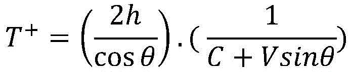

其中:in:
C:声信号的运动速度(或在温度、压力和密度条件下流体中声音的速度,C: The speed of motion of the acoustic signal (or the speed of sound in the fluid under the conditions of temperature, pressure and density,
V:流体的流速,V: flow velocity of the fluid,
h:电声换能器与表面之间的距离,h: the distance between the electro-acoustic transducer and the surface,
cos(θ):“角度θ的余弦”函数,cos(θ): "cosine of angle θ" function,
sin(θ):“角度θ的正弦”函数。sin(θ): The "sine of the angle θ" function.
“h”和“θ”是预先确定的,“V”是由空气速度指示器最终确定的流体的流速。"h" and "θ" are predetermined, and "V" is the flow velocity of the fluid as determined ultimately by the air velocity indicator.
由于声信号的运动速度C会根据温度、流体压力或流体密度而变化,并且由于往返行程距离R-A-E-A-R(角度“θ”的函数和距离“h”的函数),因此,可通过简单测量往返行程时间R-A-E-A-R(T++T-)(或参考时间)来确定声信号的运动速度。换句话说,可通过对往返行程时间(或参考时间)的测量(称为校准测量)来校准电子装置200。Since the motion speed C of the acoustic signal varies depending on the temperature, fluid pressure, or fluid density, and because the round-trip distance RAEAR (a function of the angle "θ" and a function of the distance "h"), the round-trip time can be measured by simply measuring RAEAR(T + +T - ) (or reference time) to determine the velocity of motion of the acoustic signal. In other words, the
有利地,电子装置200因此可免去用于测量流体的温度、压力或密度的元件。这减小了电子装置200的尺寸、重量和复杂性。因此,这增加了电子装置200的可靠性。这是因为校准操作由于不依赖于温度、压力或密度的一个或多个测量(所述测量结果可能是错误的)而是可靠的。因此,电子装置200适于根据距离h、参考时间(或往返行程时间R-A-E-A-R)以及角度θ确定流体中所谓的参考声信号(换句话说,声音)“C”的速度。流体中声音的速度称为运动速度“C”。Advantageously, the
应当注意,往返行程时间R-A-E-A-R等于往返行程时间E-A-R-A-E,在两种情况下,流体的流动的影响最终都是均衡的。It should be noted that the round trip time R-A-E-A-R is equal to the round trip time E-A-R-A-E, in both cases the effect of the fluid flow is ultimately equalized.
因此,运动速度C可表示为:Therefore, the motion speed C can be expressed as:

其中:in:
C:在温度、压力和密度条件下,流体中声信号的运动速度(或声音的速度),C: Under the conditions of temperature, pressure and density, the movement speed of the acoustic signal (or the speed of sound) in the fluid,
h:电声换能器与表面之间的距离,h: the distance between the electro-acoustic transducer and the surface,
T+:往返行程时间E-A-R,T + : round trip time EAR,
T-:往返行程时间R-A-E,T − : round trip time RAE,
cos(θ):“角度θ的余弦”函数。cos(θ): "cosine of angle θ" function.
h和θ是预先确定的。h and θ are predetermined.
有利地,距离h是预先确定的,以便减小电子装置200的整体尺寸。Advantageously, the distance h is predetermined in order to reduce the overall size of the
有利地,可快速且容易地确定声信号的运动速度C,并因此,在温度、压力和/或密度条件改变时进行更新。Advantageously, the speed of motion C of the acoustic signal can be quickly and easily determined and thus updated when temperature, pressure and/or density conditions change.
根据本发明的实施方式,电子装置200周期性地(例如,每10毫秒)执行校准测量,并因此,在存储器中记录定期更新的C的值。According to an embodiment of the present invention, the
根据本发明的可选实施方式,可选安装的、与流体流动的轴正入射的第三电声换能器209允许在实际温度、湿度和压力条件的环境中瞬时确定运动速度C。由第三电声换能器209发射的声波的路径与流动方向正交,因此所测量的速度独立于运动流体的速度。According to an alternative embodiment of the invention, an optionally installed third electro-
电子装置200适于经由声换能器E发射声信号。该信号在表面203(点A)上的第一反射之后由电声换能器R接收。到达电声换能器R后,该声信号被电声换能器R的表面反射,并经由表面203上的反射朝向电子声换能器E进行反向行程R-A-E。该行程的持续时间为先前定义的持续时间T-。一旦到达电声换能器E,该信号就被电声换能器E的表面反射,并再次经由表面203上的反射朝向电声换能器R进行反向行程E-A-R。该行程的持续时间为先前定义的持续时间T+。换句话说,在由电声换能器E发射声信号并由电声换能器R接收该声信号之后,采集系统观察往返行程R-A-E-A-R并监控声信号到达电声换能器R处、以及随后到达电声换能器E处和再次到达电声换能器R处的时间。换句话说,在从电声换能器E发射声信号之后,一旦声信号到达电声换能器R上(瞬时“t1”),电子装置200就确定测量结果,然后电子装置200确定反射声信号到达电声换能器E的时间(时刻“t2”),以及最后电子装置200确定再次反射的声信号到达电声换能器R上时间(瞬时“t3”)。行程R-A-E的持续时间为“T-=t2-t1”,并且行程E-A-R的持续时间为“T+=t3-t2”。因此,电子装置200适于根据行程时间T+和T-确定参考声音的速度C以及流体的流速。The
为此,电子装置200可实现以下一种或多种方法:To this end, the
(A)通过测量声信号的行进时间来测量流体的流速,(A) Measure the flow velocity of the fluid by measuring the travel time of the acoustic signal,
(B)通过测量多普勒效应来测量流体的流速,(B) measure the flow velocity of the fluid by measuring the Doppler effect,
(C)通过测量拍频来测量流体的流速。(C) The flow velocity of the fluid is measured by measuring the beat frequency.
方法(A)情况:行进时间的测量Method (A) case: measurement of travel time
对应于行程E-A-R的行进时间T+和对应于行程R-A-E的行进时间T-可这样表示:The travel time T + corresponding to the trip EAR and the travel time T − corresponding to the trip RAE can be expressed as follows:


其中:in:
T+/T-:向外行程E-A-R/R-A-E的行进时间,这些行进时间由电子装置200测量,T + /T − : the travel time of the outward travel EAR/RAE, these travel times are measured by the
h:电声换能器(E和R)与表面203之间的距离,h: distance between the electro-acoustic transducers (E and R) and the
cos(θ):“角度θ的余弦”函数,cos(θ): "cosine of angle θ" function,
sin(θ):“角度θ的正弦”函数,sin(θ): "the sine of the angle θ" function,
C:流体中声音的运动速度,如前所述,在校准测量期间确定了运动速度,C: the speed of motion of sound in the fluid, which was determined during calibration measurements as previously described,
V:流体的流速(或至少在由图2中的箭头208所限定的测量方向上的流速分量)。因此,确定的速度“V”根据流动方向是正代数量或负代数量。V: flow velocity of the fluid (or at least the flow velocity component in the direction of measurement defined by
由于除了“V”(即,流体的流速)外,所有参数都是已知的,因此可根据行进时间T+和T-的测量来确定流体的速度“V”。Since all parameters are known except "V" (ie, the flow velocity of the fluid), the velocity "V" of the fluid can be determined from the measurements of the travel times T + and T- .
然后推导出流速“V”,如下所示:The flow velocity "V" is then derived as follows:

有利地,第二声信号是依据脉冲压缩方法发射的所谓的“线性调频”类型的信号。Advantageously, the second acoustic signal is a so-called "chirp" type signal emitted according to a pulse compression method.
脉冲压缩方法基于线性频率调制原理。通过建立对声信号随时间变化的频率模式的识别,可在回声测量期间改善信噪比(SNR)。但是,在影响该频率含量的传播(散射,多普勒效应)的情况下,该技术的性能会明显下降。在这种情况下,由电声换能器E 201发送的脉冲可以是从250kHz到650kHz的频带中的线性调频脉冲。受到由流体流动引起的多普勒效应的影响,这些线性调频脉冲在传播后具有经修改的频率含量。因此,例如,在流速为0.8马赫(即,空气中声速的0.8倍)的流体流动中,频率模式从250kHz到650kHz的频率含量被修改并被转移至从180kHz至460kHz的频带。另外,仍然在流体流动的影响下,频率模式的持续时间发生变化。因此,发射的声信号和接收的声信号之间的互相关函数的最大值下降了40dB,这使得当流体以高速流动时检测反射脉冲变得更加复杂。The pulse compression method is based on the principle of linear frequency modulation. By establishing the recognition of the time-varying frequency pattern of the acoustic signal, the signal-to-noise ratio (SNR) can be improved during echometry. However, in the case of propagation (scattering, Doppler effects) that affect this frequency content, the performance of this technique degrades significantly. In this case, the pulses transmitted by the electro-
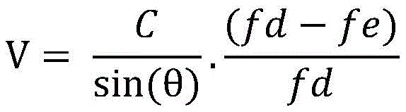
为了纠正这种可能的精度不足,以及根据本发明的补充实施方式,可实现首先考虑声速的初始值“C0”在介质中等于“C0=340m/s”的算法,该声速的初始值与通过多普勒效应测量的频移相结合,然后使得可以确定流速的第一值V0。随后使用这两个数据(C0和V0)校正通过脉冲压缩方法接收的频带。后者使得可以提取T+和T-,从而得出更精确的估计。因此可以根据C0和V0确定第二组值C1和V1。如果初始值C0与精确值C1之差超过预先确定的阈值(例如,1%),则将值C1作为新的速度初始值重新注入,并重复该过程n次,直到达到速度Cn和Cn-1之差低于预先确定的阈值。换句话说,从介质中声速的近似值开始,迭代循环将通过首先估计流速来改进该速度测量:In order to correct this possible lack of accuracy, and according to a supplementary embodiment of the invention, an algorithm can be implemented that first considers that the initial value of the speed of sound "C 0 " is equal to "C 0 =340m/s" in the medium, the initial value of the speed of sound Combined with the frequency shift measured by the Doppler effect, this then makes it possible to determine the first value V 0 of the flow velocity. These two data (C 0 and V 0 ) are then used to correct the frequency band received by the pulse compression method. The latter makes it possible to extract T + and T- , leading to a more precise estimate. The second set of values C 1 and V 1 can therefore be determined from C 0 and V 0 . If the difference between the initial value C0 and the exact value C1 exceeds a predetermined threshold (e.g., 1%), the value C1 is re-injected as a new velocity initial value, and the process is repeated n times until the velocity Cn is reached The difference between and Cn -1 is below a predetermined threshold. In other words, starting from an approximation of the speed of sound in the medium, the iterative loop will improve this velocity measurement by first estimating the flow velocity:
V0=(C0/sin(θ)).(fd-fe)/fd,V 0 =(C 0 /sin(θ)).(f d -f e )/fd,
下面在情况B的描述中描述fd和fe。f d and f e are described in the description of case B below.
接下来,该流速将用于估计线性调频脉冲的频率间隔及其持续时间的变化,从而改善其分辨率。在第n次迭代中,线性调频脉冲提供了流速V(表示为Vn)和介质C中的声速(表示为Cn)的新的更可靠的估计。如果Cn的值与Cn-1的值相差很大(也就是说,相差超过某个预先确定的百分比,例如,大于1%),则根据Cn和Vn的新值重新开始循环。Next, this flow rate will be used to estimate changes in the frequency interval of chirps and their duration, improving their resolution. In the nth iteration, the chirp provides new and more reliable estimates of the flow velocity V (denoted V n ) and the speed of sound in the medium C (denoted C n ). If the value of Cn differs significantly from the value of Cn -1 (that is, by more than some predetermined percentage, eg, greater than 1%), the cycle is restarted based on the new values of Cn and Vn .
从而,声信号有利地是线性调频类型的信号,其在250kHz至650kHz的频率范围内是线性的。电子装置200然后可确定由电声换能器E发射的声信号与由电声换能器E和R接收的反射信号之间的相互关系,以便获得相应的向外E-A-R行程时间T+和相应的向外R-A-E行程时间T-的精确测量。Thus, the acoustic signal is advantageously a chirp-type signal, which is linear in the frequency range of 250 kHz to 650 kHz. The
方法(B):通过测量多普勒效应来测量流体的流速Method (B): Measuring the flow velocity of the fluid by measuring the Doppler effect
对于该方法(B),由声换能器E发射的声信号有利地是具有高斯包络的单频谐波信号。根据所用的电声换能器的类型,最佳频率可为380kHz。For this method (B), the acoustic signal emitted by the acoustic transducer E is advantageously a single-frequency harmonic signal with a Gaussian envelope. Depending on the type of electro-acoustic transducer used, the optimum frequency may be 380kHz.
方法(B)在其向外行程E-A-R期间使用影响声信号的多普勒效应。这是因为,流体的流速越大,电声换能器E发射的声信号与电声换能器R接收的声信号之间就存在越多的频率偏移(从左向右朝向低频流动)。Method (B) uses the Doppler effect which affects the acoustic signal during its outward journey E-A-R. This is because, the greater the flow velocity of the fluid, the more frequency shift exists between the acoustic signal emitted by the electro-acoustic transducer E and the acoustic signal received by the electro-acoustic transducer R (flowing from left to right toward low frequencies) .
因此,电子装置200适于根据先前确定的参考声速(运动速度C),根据声信号(由电声换能器E发射)以及根据反射的声信号(在表面203上反射后由电声换能器R接收),根据下式确定流体的流速V:Thus, the

其中:in:
fe:由电声换能器E发射的单频声信号的频率,可能通过对发射的声信号进行快速傅立叶变换(FFT)而确定,f e : the frequency of the single-frequency acoustic signal emitted by the electroacoustic transducer E, possibly determined by performing a Fast Fourier Transform (FFT) on the emitted acoustic signal,
fd:由电声换能器R接收的单频信号的频率,可能通过对接收到的声信号进行快速傅立叶变换(FFT)而确定,f d : the frequency of the single-frequency signal received by the electroacoustic transducer R, possibly determined by performing a Fast Fourier Transform (FFT) on the received acoustic signal,
sin(θ):“角度θ的正弦”函数,sin(θ): "the sine of the angle θ" function,
C:流体中声音的运动速度,如前所述,在校准测量期间确定运动速度,C: the speed of motion of the sound in the fluid, which is determined during calibration measurements as previously described,
V:流体的流速(或至少在图2中的箭头所定义的测量方向上的流速分量)。V: flow velocity of the fluid (or at least the flow velocity component in the direction of measurement defined by the arrows in Figure 2).
根据本发明的实施方式,在该方法B中使用的运动速度C可使用如前所述的方法A,或者借助于垂直于流体流动方向布置的第三电声换能器209来确定。According to an embodiment of the present invention, the motion velocity C used in this method B can be determined using method A as described above, or by means of a third electro-
方法(C)情况:通过测量拍频来测量流体的流速Method (C) Case: Measure the flow velocity of the fluid by measuring the beat frequency
对于该方法(C),声信号有利地是单频谐波声信号。这是由一串正弦脉冲(通常为700个脉冲)组成的间歇性的声学所谓的突发信号。根据使用的电声换能器的类型,最佳频率可为380kHz。For this method (C), the acoustic signal is advantageously a single-frequency harmonic acoustic signal. This is an intermittent acoustic so-called burst signal consisting of a train of sinusoidal pulses (typically 700 pulses). Depending on the type of electro-acoustic transducer used, the optimum frequency may be 380kHz.
因此,电子装置200适于根据先前确定的声音的参考速度(运动速度C),根据第二声信号(由电声换能器E发射)以及根据反射的声信号(在表面203上反射后由电声换能器R接收),通过使第二声信号和接收到的声信号相加来确定流体的流速。将这两个声信号(至少,控制模块205使用的这两个声信号的电表示)相加显示调幅信号(或拍频)。测量调制频率使得可以由此推断出频率差,从而推断出流体的流速。Thus, the
根据本发明的实施方式,该方法C中使用的运动速度C可使用前述方法A,或者借助于垂直于流体的流动方向布置的第三电声换能器209来确定。According to an embodiment of the present invention, the movement speed C used in this method C can be determined using the aforementioned method A, or by means of a third electro-
有利地,电子装置200适于执行方法(A)、(B)或(C)中的一种或另一种,以便确定流体的流速。有利地,电子装置200可周期性地执行每一种方法(A)、(B)或(C),以便通过不同的方法获得流体的流速的测量值。有利地,电子装置200的可靠性因此得以增强。这是因为可能发生的情况是,根据电子装置200的使用条件,方法(A)、(B)或(C)中的一种或另一种给出错误的结果。因此,具有来自三种不同方法的测量值可消除相对于其他两个测量值不一致的测量值。Advantageously, the
有利地,对于允许测量高达84m/s的速度的本发明的实施方式,电声换能器E和电声换能器R是在250kHz至650kHz的频率范围内运作的非接触超声传感器(NCU),例如,约400kHz。Advantageously, for the embodiment of the invention that allows the measurement of velocities up to 84m/s, the electroacoustic transducers E and R are non-contact ultrasonic transducers (NCU) operating in the frequency range of 250kHz to 650kHz , for example, about 400kHz.
有利地,这些超声波传感器具有宽的频率范围,其允许有效地实施测量方法(A)、(B)和(C)。Advantageously, these ultrasonic sensors have a wide frequency range, which allows efficient implementation of the measurement methods (A), (B) and (C).
有利地,电声换能器E和/或电声换能器R被称为空气耦合型的。然后,电声换能器E和/或电声换能器R包括在换能器前面的表面处理(例如,聚合物层),所述表面处理允许电声换能器和流体之间进行声阻抗匹配。Advantageously, the electro-acoustic transducer E and/or the electro-acoustic transducer R is said to be of the air-coupled type. The electro-acoustic transducer E and/or the electro-acoustic transducer R then includes a surface treatment (e.g., a polymer layer) in front of the transducer that allows acoustic communication between the electro-acoustic transducer and the fluid. Impedance matching.
所讨论的流体可以是所谓的“轻”流体,即,气体,或者所谓的“重”流体,即,液体。在将电子装置用作飞机的空速指示器的情况下,所讨论的流体是空气。The fluid in question may be a so-called "light" fluid, ie a gas, or a so-called "heavy" fluid, ie a liquid. In the case of electronic devices used as airspeed indicators for aircraft, the fluid in question is air.
图3示意性地示出了在本发明的实施方式中适于测量流体的流速的电子装置300的硬件架构。电子装置300通常是图2中的电子装置200。Fig. 3 schematically shows the hardware architecture of an
模块301是工作频率为400kHz的NCU类型的换能器。模块301允许将输入的声信号(未示出)转换为电信号,所述电信号被传输到模块302以及下面等等进行处理。
模块302是电荷放大器,允许在换能器(模块301)和模块303之间进行阻抗匹配。
模块303是高通滤波器。模块303通常是截止频率约为10kHz的四阶无源高通滤波器。该模块303使得可以过滤由流体的流动产生的低频干扰频率。这是因为流动产生低频声压。
模块304是低通滤波器。模块304通常是2.5MHz的抗混叠滤波器。
模块305是放大器。通常放大电信号以使得电信号的幅度适于随后的模数转换模块306。放大通常为20dB。
模块306是采集模块,其允许将模拟电信号转换为数字信号。采集模块通常允许以5MS/s进行16位采样。
图4示意性地示出了根据本发明的可选实施方式的适于测量流体的流速的电子装置400的硬件架构。Fig. 4 schematically shows the hardware architecture of an
电子装置400对应于例如图2中的电子装置200。The
电子装置400包括通过通信总线连接的:处理器或CPU(中央处理单元)401、RAM(随机存取存储器)和/或ROM(只读存储器)类型的存储器MEM 402、网络模块NET 403,以及内部存储类型的存储模块STCK 404。存储模块STCK 404可以是硬盘类型的HDD(硬盘驱动器)或SSD(固态驱动器),或者是外部存储介质读取器类型,例如,SD(安全数字)卡读取器。处理器CPU 401可将数据或信息记录在存储器MEM 402中或存储模块STCK 404中。处理器CPU 401可读取记录在存储器MEM 402中的、在存储模块STCK 404中的或在数据库中的数据。这些数据可对应于配置参数。网络模块NET 303允许将电子装置400连接到通信网络,例如,连接到飞机的机载系统的网络。网络模块NET 403使电子装置400能够发送和分别接收针对航空电子系统的一项或多项设备并分别来自航空电子系统的一项或多项设备的消息。
处理器CPU 401能够执行加载存储器MEM 402中的指令,例如,来自存储模块STCK404或来自经由网络模块NET 403的通信网络。当电子装置400通电时,处理器CPU 401能够从存储器MEM 402读取指令并执行它们。这些指令形成计算机程序,引起处理器CPU 401实施上述所有或一些方法和步骤,特别是在图2的描述中。这些指令可对应于校准方法和/或前述方法(A)、(B)和/或(C)。因此,可通过由诸如DSP(数字信号处理器)或微控制器的可编程机器执行一组指令来以软件形式实现上述所有或一些方法和步骤。本文描述的所有或一些方法和步骤也可通过机器或专用组件(例如,FPGA(现场可编程门阵列)或ASIC(专用集成电路))以硬件形式实现。The processor CPU 401 is able to execute instructions in the
有利地,电子装置200、电子装置300、电子装置400包括:用于将所述电子装置附接至飞机的机身的附接系统。Advantageously, the
Claims (6)


Applications Claiming Priority (3)
| Application Number | Priority Date | Filing Date | Title |
|---|---|---|---|
| FR1853483A FR3080455B1 (en) | 2018-04-20 | 2018-04-20 | ULTRASONIC ANEMOMETER |
| FR1853483 | 2018-04-20 | ||
| PCT/EP2019/060218 WO2019202139A1 (en) | 2018-04-20 | 2019-04-19 | Ultrasonic anemometer |
Publications (2)
| Publication Number | Publication Date |
|---|---|
| CN112166329A CN112166329A (en) | 2021-01-01 |
| CN112166329B true CN112166329B (en) | 2023-04-14 |
Family
ID=63080055
Family Applications (1)
| Application Number | Title | Priority Date | Filing Date |
|---|---|---|---|
| CN201980027132.4A Active CN112166329B (en) | 2018-04-20 | 2019-04-19 | supersonic airspeed indicator |
Country Status (5)
| Country | Link |
|---|---|
| US (1) | US11614460B2 (en) |
| EP (1) | EP3781952B1 (en) |
| CN (1) | CN112166329B (en) |
| FR (1) | FR3080455B1 (en) |
| WO (1) | WO2019202139A1 (en) |
Families Citing this family (1)
| Publication number | Priority date | Publication date | Assignee | Title |
|---|---|---|---|---|
| CN112162110A (en) * | 2020-09-22 | 2021-01-01 | 烟台南山学院 | Ultrasonic wind direction and speed instrument |
Citations (7)
| Publication number | Priority date | Publication date | Assignee | Title |
|---|---|---|---|---|
| DE2936909A1 (en) * | 1978-09-14 | 1980-03-27 | Fuji Electric Co Ltd | Ultrasonic flowmeter for pipeline - consists of acoustic converter pairs, triggered by transit time circuit to emit short duration pulses for flow measurement |
| US4308754A (en) * | 1979-10-19 | 1982-01-05 | Panametrics, Inc. | Ultrasonic flowmeter |
| US4333353A (en) * | 1980-07-28 | 1982-06-08 | Joseph Baumoel | Two-transducer Doppler flowmeter with swept oscillator |
| JPS57108625A (en) * | 1980-12-25 | 1982-07-06 | Yokogawa Hokushin Electric Corp | Flowmeter for underground pipe |
| US6487916B1 (en) * | 2000-02-02 | 2002-12-03 | Bechtel Bxwt Idaho, Llc | Ultrasonic flow metering system |
| WO2009003764A1 (en) * | 2007-06-29 | 2009-01-08 | Continental Automotive Gmbh | Ultrasonic measuring device |
| CN103808379A (en) * | 2012-11-14 | 2014-05-21 | 丹尼尔测量和控制公司 | System and method for ultrasonic metering using an orifice meter fitting |
Family Cites Families (5)
| Publication number | Priority date | Publication date | Assignee | Title |
|---|---|---|---|---|
| US4028938A (en) * | 1976-01-26 | 1977-06-14 | Ocean Research Equipment, Inc. | Acoustical flow meter |
| DE10361464A1 (en) * | 2003-12-23 | 2005-07-28 | Endress + Hauser Flowtec Ag, Reinach | Device for determining and / or monitoring the volume and / or mass flow rate of a measuring medium |
| DE102005025671B3 (en) * | 2005-06-03 | 2006-12-21 | Siemens Ag | Method and device for measuring the specific gravity of a gaseous or liquid medium |
| ES2785321T3 (en) * | 2014-12-17 | 2020-10-06 | Reliance Worldwide Corp | Fluid flow meter, method of identifying a pipe type and computer-readable medium |
| US10309813B2 (en) * | 2015-05-15 | 2019-06-04 | Reliance Worldwide Corporation | Method and system for fluid flow rate measurement |
-
2018
- 2018-04-20 FR FR1853483A patent/FR3080455B1/en active Active
-
2019
- 2019-04-19 US US17/047,966 patent/US11614460B2/en active Active
- 2019-04-19 WO PCT/EP2019/060218 patent/WO2019202139A1/en not_active Ceased
- 2019-04-19 EP EP19718176.1A patent/EP3781952B1/en active Active
- 2019-04-19 CN CN201980027132.4A patent/CN112166329B/en active Active
Patent Citations (7)
| Publication number | Priority date | Publication date | Assignee | Title |
|---|---|---|---|---|
| DE2936909A1 (en) * | 1978-09-14 | 1980-03-27 | Fuji Electric Co Ltd | Ultrasonic flowmeter for pipeline - consists of acoustic converter pairs, triggered by transit time circuit to emit short duration pulses for flow measurement |
| US4308754A (en) * | 1979-10-19 | 1982-01-05 | Panametrics, Inc. | Ultrasonic flowmeter |
| US4333353A (en) * | 1980-07-28 | 1982-06-08 | Joseph Baumoel | Two-transducer Doppler flowmeter with swept oscillator |
| JPS57108625A (en) * | 1980-12-25 | 1982-07-06 | Yokogawa Hokushin Electric Corp | Flowmeter for underground pipe |
| US6487916B1 (en) * | 2000-02-02 | 2002-12-03 | Bechtel Bxwt Idaho, Llc | Ultrasonic flow metering system |
| WO2009003764A1 (en) * | 2007-06-29 | 2009-01-08 | Continental Automotive Gmbh | Ultrasonic measuring device |
| CN103808379A (en) * | 2012-11-14 | 2014-05-21 | 丹尼尔测量和控制公司 | System and method for ultrasonic metering using an orifice meter fitting |
Also Published As
| Publication number | Publication date |
|---|---|
| FR3080455B1 (en) | 2020-07-17 |
| CN112166329A (en) | 2021-01-01 |
| EP3781952B1 (en) | 2024-10-16 |
| EP3781952A1 (en) | 2021-02-24 |
| US11614460B2 (en) | 2023-03-28 |
| US20210165017A1 (en) | 2021-06-03 |
| FR3080455A1 (en) | 2019-10-25 |
| WO2019202139A1 (en) | 2019-10-24 |
Similar Documents
| Publication | Publication Date | Title |
|---|---|---|
| EP0824669B1 (en) | System for determination of fluid flow parameters | |
| US8261610B2 (en) | Aerodynamic measurement probe of an airstream along a wall | |
| US8261609B2 (en) | Aerodynamic measurement probe and helicopter equipped with the probe | |
| EP3693746B1 (en) | Acoustic air data system | |
| US7155969B2 (en) | System for and method of acoustic and through skin air data measurement | |
| US11169173B2 (en) | Air data system architectures including laser air data and acoustic air data sensors | |
| US10739371B2 (en) | Acoustic airspeed sensors | |
| US2869366A (en) | Vortex frequency airspeed indicator | |
| CN112166329B (en) | supersonic airspeed indicator | |
| CA3061994C (en) | Acoustic air data sensing systems with skin friction sensors | |
| EP3882639B1 (en) | Acoustic air data system with radially paired receivers | |
| EP3995835B1 (en) | Acoustic airspeed sensors and processing techniques | |
| EP3730947B1 (en) | Acoustic air data systems | |
| WO2018177271A1 (en) | Ultrasonic distance measurement device and method and related unmanned aerial vehicle | |
| CN206618776U (en) | Flow rate measuring device based on ultrasonic reflections signal | |
| US12554042B2 (en) | System and method for high speed sonic temperature and airspeed measurements for inputs to an air data system | |
| BR102019026623B1 (en) | ACOUSTIC AIR DATA CAPTURE SYSTEM AND METHOD | |
| HK1002969B (en) | System for determination of fluid flow parameters |
Legal Events
| Date | Code | Title | Description |
|---|---|---|---|
| PB01 | Publication | ||
| PB01 | Publication | ||
| SE01 | Entry into force of request for substantive examination | ||
| SE01 | Entry into force of request for substantive examination | ||
| GR01 | Patent grant | ||
| GR01 | Patent grant |