CN112161555A - Finish machining method for large-scale sliding block guide surface of low-speed diesel engine - Google Patents
Finish machining method for large-scale sliding block guide surface of low-speed diesel engine Download PDFInfo
- Publication number
- CN112161555A CN112161555A CN202011057369.8A CN202011057369A CN112161555A CN 112161555 A CN112161555 A CN 112161555A CN 202011057369 A CN202011057369 A CN 202011057369A CN 112161555 A CN112161555 A CN 112161555A
- Authority
- CN
- China
- Prior art keywords
- guide plane
- dial indicator
- guide
- numerical control
- distance
- Prior art date
- Legal status (The legal status is an assumption and is not a legal conclusion. Google has not performed a legal analysis and makes no representation as to the accuracy of the status listed.)
- Granted
Links
Images

Classifications
-
- G—PHYSICS
- G01—MEASURING; TESTING
- G01B—MEASURING LENGTH, THICKNESS OR SIMILAR LINEAR DIMENSIONS; MEASURING ANGLES; MEASURING AREAS; MEASURING IRREGULARITIES OF SURFACES OR CONTOURS
- G01B5/00—Measuring arrangements characterised by the use of mechanical techniques
- G01B5/28—Measuring arrangements characterised by the use of mechanical techniques for measuring roughness or irregularity of surfaces
-
- G—PHYSICS
- G01—MEASURING; TESTING
- G01B—MEASURING LENGTH, THICKNESS OR SIMILAR LINEAR DIMENSIONS; MEASURING ANGLES; MEASURING AREAS; MEASURING IRREGULARITIES OF SURFACES OR CONTOURS
- G01B21/00—Measuring arrangements or details thereof, where the measuring technique is not covered by the other groups of this subclass, unspecified or not relevant
-
- G—PHYSICS
- G01—MEASURING; TESTING
- G01B—MEASURING LENGTH, THICKNESS OR SIMILAR LINEAR DIMENSIONS; MEASURING ANGLES; MEASURING AREAS; MEASURING IRREGULARITIES OF SURFACES OR CONTOURS
- G01B5/00—Measuring arrangements characterised by the use of mechanical techniques
- G01B5/14—Measuring arrangements characterised by the use of mechanical techniques for measuring distance or clearance between spaced objects or spaced apertures
Abstract
The invention discloses a finish machining method for a large-scale sliding block guide surface of a low-speed diesel engine, which comprises the following steps: s1, performing first workpiece machining, and respectively finish-milling guide planes on two sides; s2, adopting a dial indicator to measure the planeness of the two guide surfaces respectively; s3, respectively measuring the distance between the first guide plane and the second intersection line and the distance between the second guide plane and the first intersection line by using a dial indicator, and calculating the symmetry degree and the distance between the first guide plane and the second guide plane according to a formula; and S4, carrying out three-coordinate measurement on the inspected first workpiece, comparing the measured measurement data with the measurement data corresponding to S2 and S3, and correcting the processing parameters according to the deviation value to process the subsequent workpieces. The method can effectively solve the problems of difficult measurement and large measurement error of the geometric tolerance of the large-sized slide block, corrects the processing parameters by combining three-coordinate measurement, and improves the finish machining precision of the guide surface of the large-sized slide block.
Description
Technical Field
The invention relates to machining of parts of a low-speed diesel engine, in particular to a finish machining method of a guide surface of a large sliding block of the low-speed diesel engine.
Background
Because the total length of the large-scale sliding block of the low-speed diesel engine reaches 1400mm or more, the appearance is large, errors of corresponding size and form and position tolerance can be linearly amplified, and a large-scale measuring tool is heavy and has high requirements on measuring hand feeling, so that the measuring difficulty and the measuring error ratio are large, and the machining precision of the guide surface is difficult to ensure.
Disclosure of Invention
The invention aims to provide a finish machining method for a large-scale sliding block guide surface of a low-speed diesel engine, which can effectively solve the problems of difficult measurement of form and position tolerance and large measurement error of a large-scale sliding block, corrects machining parameters by combining three-coordinate measurement and improves the finish machining precision of the large-scale sliding block guide surface.
The invention relates to a finish machining method for a guide surface of a large-sized sliding block of a low-speed diesel engine, which comprises the following steps of:
and S1, performing first workpiece machining, wherein the first workpiece means: the first or former products are processed after the change of the process or the change of the process at the beginning of each shift, such as the change of personnel, the change of material and tooling, the adjustment of a machine tool, the change and the repair of tooling and tools, and the like. For high volume production, the "first" piece often refers to a certain number of samples.
Fixing a slider body on a workbench through a fixture, wherein an inner hole penetrating in the axial direction is formed in the middle of the slider body, guide side plates are arranged on two sides of the slider body, the outer surfaces of the guide side plates are planes, namely a first guide plane and a second guide plane, and the first guide plane and the second guide plane on the two sides are respectively finish-milled;
s2, measuring the vertical longitudinal levelness and the horizontal transverse levelness of the first guide plane by using a dial indicator, thereby determining the planeness of the first guide plane and measuring the planeness of the second guide plane in the same way;
s3, respectively marking two intersecting lines of the shaft section of the sliding block body perpendicular to the first guide plane and the inner hole as a first intersecting line and a second intersecting line, wherein the first intersecting line is close to the first guide plane, respectively measuring the distance D1 between the first guide plane and the second intersecting line and the distance D2 between the second guide plane and the first intersecting line by using a dial indicator, and calculating the symmetry and the distance between the first guide plane and the second guide plane according to a formula;
the symmetry degree = | D1-D2 |, the distance between the first guide plane and the second guide plane = D1+ D2-phi, and phi is the diameter of the inner hole of the sliding block body;
and S4, carrying out three-coordinate measurement on the inspected first piece, comparing the measured flatness of the first guide plane, the flatness of the second guide plane, the symmetry of the first guide plane and the second guide plane and the distance between the first guide plane and the second guide plane with the measured data corresponding to S2 and S3, correcting the processing parameters according to the deviation value of the measured data, and processing the subsequent workpiece.
Further, the measurement of D1 and D2 in S3 specifically comprises the following steps:
A. clamping and fixing the sliding block body by adopting a numerical control workbench, fixing the dial indicator on a bracket, adjusting the position of the bracket to enable a measuring head of the dial indicator to abut against a second intersection line of the inner hole, and reading the reading of a pointer of the dial indicator;
B. keeping the position of the bracket unchanged, moving the numerical control workbench to enable a measuring head of the dial indicator to abut against a third intersection line, wherein the third intersection line is the intersection line of the first guide plane and the section of the slide block body perpendicular to the first guide plane, so that the reading of the pointer of the dial indicator is the same as that of the pointer of the dial indicator in the step A, and the horizontal distance of the numerical control workbench during two readings is taken as D1;
C. d2 was measured in the same manner.
Further, the moving of the numerical control workbench in the step B specifically includes: and C, horizontally moving the numerical control workbench firstly to enable the second intersecting line to be separated from the measuring head of the dial indicator, then vertically moving the numerical control workbench downwards to avoid interference between the slide block body and the dial indicator in the subsequent horizontal moving process, then continuously horizontally moving the numerical control workbench until the dial indicator is positioned above the third intersecting line, finally vertically moving the numerical control workbench upwards, wherein the vertical upwards moving distance is the same as the vertical downwards moving distance, and horizontally finely adjusting the numerical control workbench to enable the reading of the pointer of the dial indicator to be the same as the reading of the pointer of the dial indicator in the step A.
Further, anchor clamps in S1 include base and a plurality of clamping component, on the base was fixed in the workstation, base top surface middle part was equipped with the hole that corresponds complex location boss with slider body, and single clamping component includes clamp plate, support column and stud, the clamp plate middle part is equipped with the through-hole, support column lower extreme and stud lower extreme all with base threaded connection, the stud upper end passes the through-hole on the clamp plate and is connected with fastening nut, the clamp plate both ends are pressed respectively on support column upper end and slider body.
Compared with the prior art, the invention has the following beneficial effects.
1. According to the invention, the flatness of the first guide plane, the flatness of the second guide plane, the distance D1 between the first guide plane and the second intersection line and the distance D2 between the second guide plane and the first intersection line are measured after the first workpiece is machined, the symmetry of the first guide plane and the second guide plane and the distance between the first guide plane and the second guide plane are calculated according to a formula, and machining parameters are corrected by combining three-coordinate measurement data, so that the machining efficiency and the machining precision of subsequent workpieces are improved.
2. The invention realizes the distance measurement by using the dial indicator and the numerical control workbench in a matching way, has simple and controllable measuring tool and lower requirement on measuring hand feeling, and reduces the measuring error.
Drawings
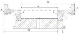
FIG. 1 is a top view of a slider body according to the present invention;
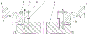
FIG. 2 is a schematic view of the clamping of the slider body of the present invention;
FIG. 3 is a schematic illustration of an inspection of a slider body according to the present invention.
In the figure, 1, a sliding block body, 2, an inner hole, 3, a first guide plane, 4, a second guide plane, 5, a base, 51, a positioning boss, 6, a pressing plate, 7, a supporting column, 8, a double-end stud and 9, a fastening nut;
a is the first intersection line, B is the second intersection line, M is the third intersection line, N is the fourth intersection line.
Detailed Description
The present invention will be described in detail with reference to the accompanying drawings.
The fine machining method of the guide surface of the large-sized sliding block of the low-speed diesel engine comprises the following steps of:
and S1, performing first workpiece machining, wherein the first workpiece means: the first or former products are processed after the change of the process or the change of the process at the beginning of each shift, such as the change of personnel, the change of material and tooling, the adjustment of a machine tool, the change and the repair of tooling and tools, and the like. For high volume production, the "first" piece often refers to a certain number of samples.
Referring to fig. 1, the slider body 1 is provided with an inner hole 2 penetrating axially in the middle, the inner hole 2 is connected with a crosshead pin, two sides of the slider body are provided with guide side plates, and the outer surfaces of the guide side plates are planes, namely a first guide plane 3 and a second guide plane 4. The length of the slide block body is 1470mm, and the width of the guide side plate is 900 mm.
On being fixed in numerical control workstation with slider body 1 through anchor clamps, see figure 2, anchor clamps include base 5 and two clamping components, on base 5 was fixed in numerical control workstation, 5 top surfaces middle parts of base were equipped with and correspond complex location boss 51 with slider body 1's hole 2, and single clamping component includes clamp plate 6, support column 7 and stud 8, 6 middle parts of clamp plate are equipped with the through-hole, 7 lower extremes of support column and 5 threaded connection of base, 8 lower extremes of stud and 5 threaded connection of base, 8 upper ends of stud pass the through-hole on the clamp plate 6 and be connected with fastening nut 9, 6 both ends of clamp plate are pressed respectively on 7 upper ends of support column and slider body 1. The clamp has the advantages of simple structure, low manufacturing cost and stable and reliable clamping and positioning.
During clamping, place slider body 1 on base 5, the hole 2 of slider body 1 aligns clearance fit with location boss 51, perpendicular threaded connection support column 7 and stud 8 on base 5, adjust the screw in distance of support column 7 for the upper end of support column 7 flushes with hole 2 upper end, places clamp plate 6 again, and the through-hole at clamp plate 6 middle part is passed from the upper end of stud 8, clamp plate 6 both ends are pressed respectively on support column 7 upper end and slider body 1, screw up fastening nut, and the clamping of accomplishing slider body is fixed.
After the slider body 1 is clamped, the first guide plane 3 is milled finely, then the slider body 1 is rotated by 180 ℃ in the horizontal direction through the numerical control workbench, and the second guide plane 4 is milled finely.
S2, a dial indicator is used to measure the vertical longitudinal levelness and horizontal transverse levelness of the first guiding plane 3, thereby determining the flatness of the first guiding plane 3. And measuring the vertical longitudinal levelness and the horizontal transverse levelness of the second guide plane 4 by adopting a dial indicator so as to determine the planeness of the second guide plane 4.
And S3, respectively marking two intersecting lines of the axial section of the sliding block body perpendicular to the first guide plane and the inner hole as a first intersecting line A and a second intersecting line B, wherein the first intersecting line A is close to the first guide plane 3. And the intersection line of the axial section of the sliding block body perpendicular to the first guide plane and the first guide plane is taken as a third intersection line M, and the intersection line of the axial section of the sliding block body perpendicular to the first guide plane and the second guide plane is taken as a fourth intersection line N. And respectively measuring the distance D1 between the first guide plane and the second intersection line and the distance D2 between the second guide plane and the first intersection line by using a dial indicator, and specifically comprising the following steps.
A. The slide block body 1 is fixed by clamping a numerical control workbench, the dial indicator is fixed on the bracket, and the position of the bracket is adjusted to enable the measuring head of the dial indicator to be abutted against a second intersection line B of the inner hole, so that the reading of the pointer of the dial indicator is read. It should be noted that, in order to unify the inspection standards, the numerical control workbench is usually required to be finely adjusted in the horizontal direction, so that the dial indicator reading is zero.
B. Keeping the position of the bracket unchanged, horizontally moving the numerical control workbench to the right first, and correspondingly moving the base 5 to the right to drive the sliding block body 1 to move to the right due to the fixed connection of the base 5 and the numerical control workbench, so that the second intersection line B is gradually far away from the measuring head of the dial indicator. And after the second intersecting line B is separated from the measuring head of the dial indicator, the numerical control workbench vertically moves downwards for a certain distance, so that the interference between the slide block body 1 and the dial indicator in the subsequent horizontal right movement process is avoided. And D, continuing to horizontally move the numerical control workbench to the right until the dial indicator is positioned above the third intersecting line M, finally vertically moving the numerical control workbench upwards, wherein the vertical upward moving distance is the same as the vertical downward moving distance, and horizontally finely adjusting the numerical control workbench to enable the reading of the pointer of the dial indicator to be the same as the reading of the pointer of the dial indicator in the step A. The measuring head of the dial indicator is abutted against the second intersecting line B, the position of the numerical control workbench when the reading of the pointer of the dial indicator is zero is recorded as an initial position, the measuring head of the dial indicator is abutted against the third intersecting line M, the position of the numerical control workbench when the reading of the pointer of the dial indicator is zero is recorded as an end position, the horizontal distance between the initial position and the end position of the numerical control workbench is recorded as D1, namely the horizontal distance of the numerical control workbench is taken as D1 when the reading is carried out twice.
C. The slide block body 1 is fixed by clamping a numerical control workbench, the dial indicator is fixed on the bracket, the position of the bracket is adjusted to enable the measuring head of the dial indicator to be abutted against a first intersection line A of an inner hole, and the numerical control workbench is finely adjusted in the horizontal direction to enable the pointer of the dial indicator to be zero in reading. Keeping the position of the bracket unchanged, horizontally moving the numerical control workbench leftwards to enable the first intersection line A to be gradually far away from the measuring head of the dial indicator. After the first intersecting line A is separated from the measuring head of the dial indicator, the numerical control workbench vertically moves downwards for a certain distance, and interference between the slide block body 1 and the dial indicator in the subsequent horizontal leftward movement process is avoided. And then, continuously moving the numerical control workbench horizontally leftwards until the dial indicator is positioned above a fourth intersection line N, finally, vertically moving the numerical control workbench upwards, wherein the vertical upward movement distance is the same as the vertical downward movement distance, and horizontally finely adjusting the numerical control workbench to enable the reading of the pointer of the dial indicator to be zero. The measuring head of the dial indicator is abutted against the first intersecting line A, the position of the numerical control workbench when the reading of the pointer of the dial indicator is zero is recorded as an initial position, the measuring head of the dial indicator is abutted against the fourth intersecting line N, the position of the numerical control workbench when the reading of the pointer of the dial indicator is zero is recorded as an end position, the horizontal distance between the initial position and the end position of the numerical control workbench is recorded as D2, namely the horizontal distance of the numerical control workbench is taken as D2 when the reading is carried out twice. The distance measurement can be realized by using the dial indicator and the numerical control workbench in a matching way, the measuring tool is simple and controllable, the requirement on measuring hand feeling is low, the measuring error is reduced, and the problems of difficult measurement and large measuring error of the form and position tolerance of a large-scale slide block are effectively solved.
Calculating the symmetry of the first guide plane and the second guide plane and the distance between the first guide plane and the second guide plane according to a formula;
and the symmetry degree = | -D1-D2 |, and the symmetry degree of the first guide plane and the second guide plane is directly calculated through the difference value of the two distances D1 and D2, so that the measurement difficulty is reduced, and the method is convenient and quick.
The distance between the first guide plane and the second guide plane = D1+ D2-phi, and phi is the diameter of the inner hole of the slider body and can be measured by an inside micrometer.
And S4, carrying out three-coordinate measurement on the inspected first workpiece, comparing the flatness of the first guide plane, the flatness of the second guide plane, the symmetry of the first guide plane and the second guide plane and the distance between the first guide plane and the second guide plane measured by a three-coordinate measuring machine with the measured data corresponding to S2 and S3, correcting the machining parameters according to the deviation value of the measured data, and machining the subsequent workpiece after correction. The specific correction method is the conventional technology in the prior art, and the invention is not described in detail. The mode of combining manual inspection and three-coordinate measurement is adopted, the measurement difficulty is reduced, and the processing efficiency and the processing precision of subsequent workpieces are improved.
The above description is only for the purpose of illustrating the preferred embodiments of the present invention and is not to be construed as limiting the invention, and any modifications, equivalents and improvements made within the spirit and principle of the present invention are intended to be included within the scope of the present invention.
Claims (4)
1. A finish machining method for a guide surface of a large-sized sliding block of a low-speed diesel engine is characterized by comprising the following steps:
s1, performing first workpiece processing, fixing the slide block body (1) on a workbench through a clamp, and respectively finish-milling a first guide plane (3) and a second guide plane (4) at two sides;
s2, measuring the vertical longitudinal levelness and the horizontal transverse levelness of the first guide plane (3) by adopting a dial indicator so as to determine the planeness of the first guide plane and similarly measuring the planeness of the second guide plane;
s3, marking two intersecting lines of the axial section of the sliding block body perpendicular to the first guide plane (3) and the inner hole (2) as a first intersecting line A and a second intersecting line B respectively, wherein the first intersecting line A is close to the first guide plane 3, measuring the distance D1 between the first guide plane and the second intersecting line and the distance D2 between the second guide plane and the first intersecting line respectively by using a dial indicator, and calculating the symmetry and the distance between the first guide plane (3) and the second guide plane (4) according to a formula;
the symmetry degree = | D1-D2 |, the distance between the first guide plane and the second guide plane = D1+ D2-phi, and phi is the diameter of the inner hole of the sliding block body;
and S4, carrying out three-coordinate measurement on the inspected first piece, comparing the measured flatness of the first guide plane, the flatness of the second guide plane, the symmetry of the first guide plane and the second guide plane and the distance between the first guide plane and the second guide plane with the measured data corresponding to S2 and S3, correcting the processing parameters according to the deviation value of the measured data, and processing the subsequent workpiece.
2. The finishing method for the guide surface of the large-sized sliding block of the low-speed diesel engine as claimed in claim 1, wherein the measurement of D1 and D2 in S3 specifically comprises the following steps:
A. clamping and fixing the sliding block body (1) by adopting a numerical control workbench, fixing the dial indicator on the bracket, adjusting the position of the bracket to enable a measuring head of the dial indicator to abut against a second intersection line B of the inner hole, and reading the reading of a pointer of the dial indicator;
B. keeping the position of the bracket unchanged, moving the numerical control workbench to enable a measuring head of the dial indicator to abut against a third intersecting line M, wherein the third intersecting line M is an intersecting line of the first guide plane 3 and a slide block body axial section perpendicular to the first guide plane 3, so that the reading of a pointer of the dial indicator is the same as that of the pointer of the dial indicator in the step A, and the horizontal distance of the numerical control workbench during two readings is taken as D1;
C. d2 was measured in the same manner.
3. The finish machining method for the guide surface of the large-sized sliding block of the low-speed diesel engine according to claim 2, wherein the moving of the numerical control workbench in the step B is specifically as follows: and (3) horizontally moving the numerical control workbench firstly to enable the second intersecting line B to be separated from the measuring head of the dial indicator, then vertically moving the numerical control workbench downwards to avoid interference between the slide block body (1) and the dial indicator in the subsequent horizontal moving process, then continuously horizontally moving the numerical control workbench until the dial indicator is positioned above the third intersecting line M, and finally vertically moving the numerical control workbench upwards, wherein the vertical upwards moving distance is the same as the vertical downwards moving distance, and horizontally finely adjusting the numerical control workbench to enable the reading of the pointer of the dial indicator to be the same as the reading of the pointer of the dial indicator in the step A.
4. The finish machining method for the guide surface of the large-sized sliding block of the low-speed diesel engine according to claim 1 or 2, characterized by comprising the following steps of: anchor clamps in S1 include base (5) and a plurality of clamping component, on base (5) were fixed in the workstation, base (5) top surface middle part was equipped with and corresponds complex location boss (51) with hole (2) of slider body (1), and single clamping component includes clamp plate (6), support column (7) and stud (8), clamp plate (6) middle part is equipped with the through-hole, support column (7) lower extreme and stud (8) lower extreme all with base (5) threaded connection, through-hole on clamp plate (6) is passed and fastening nut (9) are connected to stud (8) upper end, clamp plate (6) both ends press respectively on support column (7) upper end and slider body (1).
Priority Applications (1)
| Application Number | Priority Date | Filing Date | Title |
|---|---|---|---|
| CN202011057369.8A CN112161555B (en) | 2020-09-30 | 2020-09-30 | Finish machining method for large-scale sliding block guide surface of low-speed diesel engine |
Applications Claiming Priority (1)
| Application Number | Priority Date | Filing Date | Title |
|---|---|---|---|
| CN202011057369.8A CN112161555B (en) | 2020-09-30 | 2020-09-30 | Finish machining method for large-scale sliding block guide surface of low-speed diesel engine |
Publications (2)
| Publication Number | Publication Date |
|---|---|
| CN112161555A true CN112161555A (en) | 2021-01-01 |
| CN112161555B CN112161555B (en) | 2021-12-10 |
Family
ID=73860826
Family Applications (1)
| Application Number | Title | Priority Date | Filing Date |
|---|---|---|---|
| CN202011057369.8A Active CN112161555B (en) | 2020-09-30 | 2020-09-30 | Finish machining method for large-scale sliding block guide surface of low-speed diesel engine |
Country Status (1)
| Country | Link |
|---|---|
| CN (1) | CN112161555B (en) |
Citations (14)
| Publication number | Priority date | Publication date | Assignee | Title |
|---|---|---|---|---|
| US5674169A (en) * | 1982-09-28 | 1997-10-07 | Yang; Tai-Her | Tunnel type or dragon-gate type processing system assembled with selected elements and its related interface means |
| JP2001141443A (en) * | 1999-11-12 | 2001-05-25 | Matsushita Electric Ind Co Ltd | Method and instrument for measuring shape |
| JP2004058242A (en) * | 2002-07-31 | 2004-02-26 | Shiga Yamashita:Kk | Method for correcting cast deburring position deviation |
| US20040215414A1 (en) * | 2000-06-19 | 2004-10-28 | Han-Jurgen Kaisser | Method and apparatus for measuring and machining workpieces |
| US20080052035A1 (en) * | 2004-06-08 | 2008-02-28 | Fabrice Moreau | Three-Dimensional Measurement Method and Device |
| CN101235847A (en) * | 2008-02-20 | 2008-08-06 | 宁波恒力汽配轴承有限公司 | Straight-line rolling slipper block and method of manufacture |
| DE102008046740A1 (en) * | 2008-09-11 | 2010-03-18 | Schaeffler Kg | Measuring standard in profile rail guide |
| CN103090759A (en) * | 2013-01-16 | 2013-05-08 | 山东赛尔机械导轨有限公司 | Detection device and detection method of straight line guide rail pair |
| CN203615880U (en) * | 2013-11-04 | 2014-05-28 | 江苏国力锻压机床有限公司 | Linearity detecting device for processing face of slide block of bending machine |
| CN204228150U (en) * | 2014-12-09 | 2015-03-25 | 安徽池州家用机床股份有限公司 | A kind of dovetail face parallelism detecting device |
| CN108723448A (en) * | 2018-06-08 | 2018-11-02 | 山东金辰机械股份有限公司 | The processing tool and processing method of a kind of angle guide rail or inclined-plane |
| CN108788636A (en) * | 2018-06-07 | 2018-11-13 | 重庆红江机械有限责任公司 | The precision machining method of oil cylinder piston blind hole |
| CN109141296A (en) * | 2018-07-13 | 2019-01-04 | 南京理工大学 | A kind of T-type guide rail guide surface flatness detection system and method |
| CN111397490A (en) * | 2020-04-29 | 2020-07-10 | 浙江四强轴承制造有限公司 | Miniature slider detecting instrument |
-
2020
- 2020-09-30 CN CN202011057369.8A patent/CN112161555B/en active Active
Patent Citations (14)
| Publication number | Priority date | Publication date | Assignee | Title |
|---|---|---|---|---|
| US5674169A (en) * | 1982-09-28 | 1997-10-07 | Yang; Tai-Her | Tunnel type or dragon-gate type processing system assembled with selected elements and its related interface means |
| JP2001141443A (en) * | 1999-11-12 | 2001-05-25 | Matsushita Electric Ind Co Ltd | Method and instrument for measuring shape |
| US20040215414A1 (en) * | 2000-06-19 | 2004-10-28 | Han-Jurgen Kaisser | Method and apparatus for measuring and machining workpieces |
| JP2004058242A (en) * | 2002-07-31 | 2004-02-26 | Shiga Yamashita:Kk | Method for correcting cast deburring position deviation |
| US20080052035A1 (en) * | 2004-06-08 | 2008-02-28 | Fabrice Moreau | Three-Dimensional Measurement Method and Device |
| CN101235847A (en) * | 2008-02-20 | 2008-08-06 | 宁波恒力汽配轴承有限公司 | Straight-line rolling slipper block and method of manufacture |
| DE102008046740A1 (en) * | 2008-09-11 | 2010-03-18 | Schaeffler Kg | Measuring standard in profile rail guide |
| CN103090759A (en) * | 2013-01-16 | 2013-05-08 | 山东赛尔机械导轨有限公司 | Detection device and detection method of straight line guide rail pair |
| CN203615880U (en) * | 2013-11-04 | 2014-05-28 | 江苏国力锻压机床有限公司 | Linearity detecting device for processing face of slide block of bending machine |
| CN204228150U (en) * | 2014-12-09 | 2015-03-25 | 安徽池州家用机床股份有限公司 | A kind of dovetail face parallelism detecting device |
| CN108788636A (en) * | 2018-06-07 | 2018-11-13 | 重庆红江机械有限责任公司 | The precision machining method of oil cylinder piston blind hole |
| CN108723448A (en) * | 2018-06-08 | 2018-11-02 | 山东金辰机械股份有限公司 | The processing tool and processing method of a kind of angle guide rail or inclined-plane |
| CN109141296A (en) * | 2018-07-13 | 2019-01-04 | 南京理工大学 | A kind of T-type guide rail guide surface flatness detection system and method |
| CN111397490A (en) * | 2020-04-29 | 2020-07-10 | 浙江四强轴承制造有限公司 | Miniature slider detecting instrument |
Non-Patent Citations (1)
| Title |
|---|
| 张跃华: "平面加工中导向定位面支撑高度对平面加工定位误差大小的影响", 《成都大学学报:自然科学版》 * |
Also Published As
| Publication number | Publication date |
|---|---|
| CN112161555B (en) | 2021-12-10 |
Similar Documents
| Publication | Publication Date | Title |
|---|---|---|
| CN111716147B (en) | Device and method for accurately controlling and processing wall thickness error of rotary shell part | |
| CN112427969B (en) | Method for processing axial positioning surface of turntable frame | |
| CN111069977A (en) | Surface fitting, precision machining process and part size measuring method suitable for machining center | |
| CN201073735Y (en) | Gripping device for processing crystallizer brass tube | |
| CN214250916U (en) | Shaft part measuring device with center hole as axis reference | |
| CN112161555B (en) | Finish machining method for large-scale sliding block guide surface of low-speed diesel engine | |
| CN201104211Y (en) | Universal angle alignment measuring gauge | |
| CN111230589A (en) | Method for correcting perpendicularity between Y-axis sliding saddle and X-axis workbench of large numerical control gantry machining center | |
| JP5547408B2 (en) | Workpiece machining method | |
| CN217702673U (en) | A workstation guide rail grinding frock for flat grinder | |
| CN114937397B (en) | Perpendicularity tolerance detection teaching aid | |
| CN219694036U (en) | Measuring device | |
| CN110842642A (en) | Rapid centering device for wide and large plate of railway passenger car | |
| US20230384076A1 (en) | Calibration master installing jig and measuring method for calibration master in machine tool | |
| CN110614389B (en) | Boring processing method for crosshead bearing cover of large-scale low-speed marine diesel engine | |
| CN220296500U (en) | Bearing connection plate angle-adjustable machining tool | |
| CN217617059U (en) | Digital display roll bending tool | |
| CN213258205U (en) | Special clamp for finish machining of small pressing plate parts | |
| CN216967803U (en) | Hot pressing clamp offline adjusting device | |
| CN220462758U (en) | Clamp tool for welding five-way stop valve block | |
| CN210588436U (en) | Ball arm instrument special fixture for numerical control machine tool | |
| CN220170125U (en) | Thickness detection device for automobile parts | |
| CN116576750A (en) | Rapid detection device for complex space size and use method | |
| CN109746764B (en) | Ball rod instrument clamp applied to multi-axis machine tool and machining center | |
| CN108621054B (en) | Correction device and correction method for nut seat of vertical machining center |
Legal Events
| Date | Code | Title | Description |
|---|---|---|---|
| PB01 | Publication | ||
| PB01 | Publication | ||
| SE01 | Entry into force of request for substantive examination | ||
| SE01 | Entry into force of request for substantive examination | ||
| GR01 | Patent grant | ||
| GR01 | Patent grant |