CN112160770B - Tunnel reinforced concrete center ditch construction equipment and construction method thereof - Google Patents
Tunnel reinforced concrete center ditch construction equipment and construction method thereof Download PDFInfo
- Publication number
- CN112160770B CN112160770B CN202010970987.5A CN202010970987A CN112160770B CN 112160770 B CN112160770 B CN 112160770B CN 202010970987 A CN202010970987 A CN 202010970987A CN 112160770 B CN112160770 B CN 112160770B
- Authority
- CN
- China
- Prior art keywords
- die
- walking
- mould
- lifting
- lifting device
- Prior art date
- Legal status (The legal status is an assumption and is not a legal conclusion. Google has not performed a legal analysis and makes no representation as to the accuracy of the status listed.)
- Active
Links
Images


Classifications
-
- E—FIXED CONSTRUCTIONS
- E21—EARTH DRILLING; MINING
- E21D—SHAFTS; TUNNELS; GALLERIES; LARGE UNDERGROUND CHAMBERS
- E21D11/00—Lining tunnels, galleries or other underground cavities, e.g. large underground chambers; Linings therefor; Making such linings in situ, e.g. by assembling
- E21D11/04—Lining with building materials
- E21D11/10—Lining with building materials with concrete cast in situ; Shuttering also lost shutterings, e.g. made of blocks, of metal plates or other equipment adapted therefor
- E21D11/102—Removable shuttering; Bearing or supporting devices therefor
-
- E—FIXED CONSTRUCTIONS
- E21—EARTH DRILLING; MINING
- E21D—SHAFTS; TUNNELS; GALLERIES; LARGE UNDERGROUND CHAMBERS
- E21D11/00—Lining tunnels, galleries or other underground cavities, e.g. large underground chambers; Linings therefor; Making such linings in situ, e.g. by assembling
- E21D11/04—Lining with building materials
- E21D11/10—Lining with building materials with concrete cast in situ; Shuttering also lost shutterings, e.g. made of blocks, of metal plates or other equipment adapted therefor
- E21D11/105—Transport or application of concrete specially adapted for the lining of tunnels or galleries ; Backfilling the space between main building element and the surrounding rock, e.g. with concrete
-
- Y—GENERAL TAGGING OF NEW TECHNOLOGICAL DEVELOPMENTS; GENERAL TAGGING OF CROSS-SECTIONAL TECHNOLOGIES SPANNING OVER SEVERAL SECTIONS OF THE IPC; TECHNICAL SUBJECTS COVERED BY FORMER USPC CROSS-REFERENCE ART COLLECTIONS [XRACs] AND DIGESTS
- Y02—TECHNOLOGIES OR APPLICATIONS FOR MITIGATION OR ADAPTATION AGAINST CLIMATE CHANGE
- Y02E—REDUCTION OF GREENHOUSE GAS [GHG] EMISSIONS, RELATED TO ENERGY GENERATION, TRANSMISSION OR DISTRIBUTION
- Y02E10/00—Energy generation through renewable energy sources
- Y02E10/20—Hydro energy
Abstract
The invention belongs to the technical field of reinforced concrete central ditch construction, and particularly relates to a tunnel reinforced concrete central ditch construction device and a construction method thereof, which solve the defects of the traditional construction device and method. The equipment comprises a set of moulds for pouring inverted arch filling layer concrete and central ditch concrete, wherein the moulds comprise two side moulds and a bottom mould, the distance between the two side moulds is adjustable, the bottom mould is folded and stretched along the width direction of the bottom mould, and the side moulds and the bottom mould can be lifted up and down. The construction method comprises the following steps: s1, placing equipment in place; s2, supporting a formwork; s3, pouring inverted arch filling layer concrete and a construction center ditch preformed groove; s4, folding to shorten the distance between the bottom die and the small side die for die assembly; s5, binding steel bars, and pouring central ditch concrete; s6, lifting the side die and the bottom die for stripping. According to the invention, only one-time formwork support is needed, so that the construction cost is reduced, the construction efficiency is improved, and the construction period is shortened; the distance between the two side molds is adjustable, the side molds and the bottom mold can be lifted, and the service life of the template is prolonged.
Description
Technical Field
The invention belongs to the technical field of reinforced concrete central ditch construction, and particularly relates to tunnel reinforced concrete central ditch construction equipment and a construction method thereof.
Background
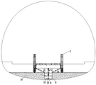
The tunnel engineering is built in an underground rock stratum, the whole tunnel structure can be surrounded by underground water, the underground water cannot enter without holes, and the tunnel water leakage prevention and drainage system is defective due to the fact that the geological exploration is not well known, and all links of design, construction and operation management are not in place, and the tunnel water leakage phenomenon is caused. The water leakage of the tunnel is one of the main defects affecting the tunnel, and is one of the most important factors affecting the normal operation and the service life of the tunnel. Therefore, in the construction of the central ditch of the tunnel, the erosive influence of the underground water flow needs to be considered, the central ditch of the tunnel is designed into a reinforced concrete structure, and the construction steps of the traditional reinforced concrete central ditch are as follows (as shown in fig. 1): formwork support → tunnel inverted arch filling layer concrete pouring → formwork removal → reinforcement binding → formwork support again → central ditch concrete pouring → formwork removal again; namely, formwork erecting, then carrying out concrete pouring on the tunnel inverted arch filling layer (reserving a central ditch preformed groove), dismantling the formwork after the pouring is finished, then binding steel bars on the inner side of the central ditch preformed groove, erecting the formwork again, carrying out the concrete pouring on the central ditch, and then dismantling the formwork. The following problems exist in the traditional reinforced concrete construction: 1. the side mold and the bottom mold are separated, the side mold adopts an integral steel film, the bottom mold is made of steel plates or wood plates, and a large amount of time is spent for assembling the template before and after each concrete pouring, so that the construction time and the construction progress are seriously delayed; 2. after the concrete pouring of the central ditch is finished, the template is difficult to remove and easy to damage, and the template needs to be frequently replaced; 3. the integrity of the template assembled on site is difficult to ensure, and the template is easy to explode in the pouring process, so that the drainage ditch is deformed, and the function of the drainage ditch is influenced; 4. the formwork is required to be supported twice, a set of formwork is difficult to meet the requirements of site construction, and the construction cost is increased invisibly; 5. and when the binding of the reinforcing steel bars of the central ditch is finished and the formwork construction is carried out, the large-scale machine can damage the surface of the poured inverted arch filling layer.
Disclosure of Invention
The invention provides a tunnel reinforced concrete central ditch construction device and a construction method thereof, aiming at solving the defects of the traditional construction device and method.
The invention is realized by adopting the following technical scheme: a kind of tunnel reinforced concrete center ditch construction equipment, including a set of moulds used for the concrete pouring of filler of the inverted arch and center ditch, the said mould includes two side forms and a bottom die, connect with the adjusting device of the side form between two side forms, used for regulating the interval of two side forms, the side form drives its up and down lift through the lifting device of the side form; the bottom die comprises a fixed bottom die and a plurality of foldable section bottom dies, and the two sides of the fixed bottom die are symmetrically and movably connected with the foldable section bottom dies, so that the bottom die can be folded and stretched along the width direction, and the bottom die is driven to lift up and down by the template lifting device.
Furthermore, the device also comprises a main truss, a travelling mechanism and a travelling platform for the operation equipment to pass up and down; the bottom of the main truss is connected with a walking mechanism for realizing the walking function of the equipment; the main truss is provided with a walking platform arranged along the length direction of the main truss;
the walking mechanism comprises a crawler-type walking system, walking wheels and a hydraulic lifting device;
the walking wheels and the crawler-type walking system are connected to the bottom of the main truss, the walking wheels are positioned at one end, close to an excavation opening, of the main truss, the crawler-type walking system is positioned at one end, close to an excavation section, of the main truss, and the height of the crawler-type walking system from the main truss is adjustable;
the walking platform comprises two lifting walking platforms and a horizontal walking platform, the two lifting walking platforms are hinged to two ends of the horizontal walking platform, the two lifting walking platforms are located at two ends of the main truss, and the lifting walking platforms rotate around the horizontal walking platform.
Furthermore, the lifting walking platform of the walking platform drives the lifting walking platform to rotate around the horizontal walking platform through the telescopic device, the trend of the telescopic device can be seen to freely stretch, the top end of the telescopic device is fixed on the main truss, and the bottom end of the telescopic device is fixed on the lifting walking platform.
Furthermore, the fixed bottom die of the bottom die is movably connected with the bottom die of the foldable section through a 90-degree hinge, and the bottom die of the foldable section can rotate around the fixed bottom die by 0-90 degrees, so that the bottom die can be folded and stretched.
Furthermore, the two foldable section bottom dies are pulled to rotate around the fixed bottom die through adjusting mechanisms, a plurality of groups of adjusting mechanisms are arranged along the length direction of the bottom dies, and each group of adjusting mechanisms comprises two foldable bottom die adjusting devices and a central connecting plate; the central connecting plate is fixed at the top of the fixed bottom die, the left side and the right side of the central connecting plate are symmetrically hinged with foldable bottom die adjusting devices, the other ends of the foldable bottom die adjusting devices are hinged at the top of the bottom die of the foldable section, and the foldable bottom die adjusting devices can freely stretch along the trend.
Furthermore, the side die adjusting device is provided with a plurality of groups along the length direction of the side die, each group is provided with a plurality of groups from top to bottom, and the side die adjusting device can freely stretch out and draw back along the length direction.
Furthermore, the side form lifting devices can freely stretch along the length direction of the side form lifting devices, a plurality of groups of side form lifting devices are arranged along the length of the side form, each group is provided with two side form lifting devices, the two side form lifting devices are symmetrically arranged on the outer side of the top end of the side form, one end of each side form lifting device is hinged to the side form, the other end of each side form lifting device is hinged to the main truss, and the stretching of the side form lifting devices drives the side form to lift;
the template lifting device is vertically arranged and can freely stretch along the moving direction of the template lifting device, the top end of the template lifting device is fixed at the bottom of the main truss, the bottom end of the template lifting device is fixed at the top of the central connecting plate, and the bottom die is driven by the stretching of the template lifting device to lift.
Further, this application still includes the control chamber, and the control chamber is located the main truss for control crawler-type traveling system, hydraulic pressure elevating gear, template hoisting device, side form adjusting device, collapsible die block adjusting device, side form hoisting device and telescoping device.
Furthermore, the template lifting device, the side die adjusting device, the foldable bottom die adjusting device, the side die lifting device and the telescopic device are all hydraulic cylinders.
A construction method of the equipment construction center ditch comprises the following steps:
s1, placing equipment in place; the main truss is moved to a designated position;
s2, supporting a formwork; adjusting the bottom moulds of the two foldable sections of the bottom mould to be horizontal to the fixed bottom mould, and descending the bottom mould and the side mould to support the mould;
s3, pouring inverted arch filling layer concrete and constructing a central ditch preformed groove; after the side mold and the bottom mold are erected, the inverted arch filling layer concrete is poured, and a groove formed after pouring is a central ditch reserved groove;
s4 folding to shorten the distance between the bottom die and the small side die for die assembly; after the inverted arch filling layer concrete reaches a preset strength, adjusting the bottom moulds of the two foldable sections of the bottom mould to be vertical to the fixed bottom mould, and then adjusting the distance between the two side moulds until the two side moulds are contacted with the bottom moulds of the two foldable sections, so as to finish mould assembly;
s5, binding steel bars, and pouring central ditch concrete; after the die assembly is completed, lifting the bottom die and the side die, then binding steel bars on the inner wall of the reserved groove of the central ditch, after the binding of the steel bars is completed, descending the bottom die and the side die, and pouring central ditch concrete between the outer sides of the side die and the bottom die and the inner wall of the reserved groove of the central ditch;
s6, lifting the side die and the bottom die for removing the die; and after the central ditch concrete reaches the preset strength, adjusting the distance between the two side dies to be smaller, lifting the bottom die and the side dies, and removing the die.
Compared with the prior art, the invention has the beneficial effects that:
1. the bottom die is designed to be foldable and telescopic, so that the concrete pouring of the inverted arch filling layer and the concrete pouring of the central ditch can be completed by using a set of templates, the formwork is only required to be erected once, the construction cost is reduced, the construction efficiency is greatly improved, and the construction period is shortened;
2. the distance between the two side molds is adjustable, the side molds and the bottom mold can be lifted, the construction efficiency is effectively improved, the smooth mold removal of the mold plate is convenient to ensure, the deformation of the mold plate during the mold removal is reduced, the service life of the mold plate is prolonged, and the repeated use times are increased;
3. the construction method comprises the steps of formwork support → inverted arch filling layer concrete pouring → automatic control of folding and shortening of the bottom formwork, adjustment of the space between the side formworks → steel bar binding → lifting of the side formworks and the bottom formwork for formwork removal, so that the construction process is simplified, the construction efficiency is greatly improved, the construction cost is reduced, and the construction period is shortened;
4. the side mould lifting device not only controls the lifting of the side mould, but also controls the stability of the whole template, and ensures the concrete pouring quality;
5. the crawler type traveling system is used for realizing the movement of the main truss, is more suitable for complex construction environments in tunnels, and is used for controlling the height of the crawler type traveling system through the hydraulic lifting device, so that the crawler type traveling system is suitable for the horizontal movement of the main truss traveling under the working conditions of different central ditch reserved groove depths, and can be used for synchronously constructing each construction section, thereby improving the efficiency, shortening the construction period and reducing the construction cost;
6. the template is convenient to disassemble and can be repeatedly used;
drawings
FIG. 1 is a schematic diagram of background art;
FIG. 2 is a schematic front projection view of the apparatus;
FIG. 3 is a schematic side projection view of the apparatus;
FIG. 4 is a schematic view of a fixed bottom mold and a bottom mold of a foldable section of the bottom mold in a horizontal state;
FIG. 5 is a schematic view of a foldable bottom mold perpendicular to a fixed bottom mold;
FIG. 6 is a schematic view of a formwork of the present construction method S2;
FIG. 7 is a schematic view of the present construction method S3 for placing inverted arch filling concrete;
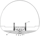
FIG. 8 is a schematic view of the construction method S4 for folding, shortening bottom die replacement and adjusting the distance between the side dies to carry out die assembly;
fig. 9 is a schematic view of the reinforcement bar binding in the construction method S5;
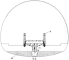
FIG. 10 is a schematic view of the center ditch concrete poured in the present construction method S5;
FIG. 11 is a schematic view of the construction method S6 for lifting the side mold and the bottom mold and removing the mold;
FIG. 12 is an enlarged view of FIG. 11 at B;
FIG. 13 is a schematic flow chart of the construction method;
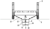
in the figure: 1-lifting walking platform; 2-a main truss; 3-an operation chamber; 4-a horizontal walking platform; 5-walking wheels; 6, a crawler-type traveling system; 7-a hydraulic lifting device; 8-side die; 9-fixing the bottom die; 10-folding section bottom die; 11-a central connection plate; 12-a formwork lifting device; 13-side die adjusting device; 14-foldable bottom die adjusting device; 15-side form lifting device; 16-an inverted arch filling layer, 17-a central ditch preformed groove, 18-reinforcing steel bars, 19-a central ditch and 20-a telescopic device.
Detailed Description
The following description of the embodiments of the present invention is provided for illustrative purposes, and other advantages and effects of the present invention will become apparent to those skilled in the art from the present disclosure.
It should be understood that the structures, ratios, sizes, etc. shown in the drawings and attached to the description are only for understanding and reading the disclosure of the present invention, and are not intended to limit the practical conditions of the present invention, so that the present invention has no technical significance, and any modifications of the structures, changes of the ratio relationships, or adjustments of the sizes, should still fall within the scope of the technical contents of the present invention without affecting the efficacy and the achievable purpose of the present invention. In addition, the terms "upper", "lower", "left", "right", "middle" and "one" used in the present specification are for clarity of description, and are not intended to limit the scope of the present invention, and the relative relationship between the terms and the terms is not to be construed as a scope of the present invention.
The terms "left-right" and "transverse" as used herein refer to the width direction of the tunnel; "front-to-back" refers to the tunnel length direction; "Up and down" and "vertical" refer to the height direction of the tunnel.
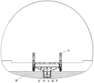
Referring to fig. 2 to 5, the present invention provides a technical solution: a kind of tunnel reinforced concrete central ditch construction equipment, including a set of moulds used for the concrete placement of 16 concrete and central ditch 19 of filler layer of inverted arch, the said mould includes two side forms 8 and a bottom die, connect with the adjusting device 13 of the side form between two side forms 8, used for regulating the interval of two side forms 8, the side form 8 drives its up and down lift through the lifting device 15 of the side form; the bottom die comprises a fixed bottom die 9 and a plurality of foldable bottom dies 10, the two sides of the fixed bottom die 9 are symmetrically and movably connected with the foldable bottom dies 10, so that the bottom die can be folded and stretched along the width direction, and the bottom die is driven to lift up and down by a template lifting device 12.
The device also comprises a main truss 2, a walking mechanism and a walking platform for the operation equipment to pass up and down; the bottom of the main truss 2 is connected with a walking mechanism for realizing the walking function of the equipment; the main truss 2 is provided with a walking platform arranged along the length direction of the main truss;
the travelling mechanism comprises a crawler-type travelling system 6, travelling wheels 5 and a hydraulic lifting device 7;
the walking wheels 5 and the crawler-type walking system 6 are connected to the bottom of the main truss 2, the walking wheels 5 are positioned at one end, close to an excavation opening, of the main truss 2, the crawler-type walking system 6 is positioned at one end, close to an excavation section, of the main truss 2, the height of the crawler-type walking system 6 from the main truss 2 is adjustable, so that the device is suitable for walking under the working conditions of different depths of the central ditch preformed grooves 17, the application range is wide, the crawler-type walking system 6 can advance and retreat at any time due to the fact that the height of the crawler-type walking system 6 from the main truss 2 is adjustable, when binding is carried out after concrete pouring of an inverted arch filling layer 16 of a previous construction section is finished in the construction process, when binding is carried out on concrete of the inverted arch filling layer 16, the crawler-type walking system 6 drives the main truss 2 to retreat to the previous construction section for concrete pouring of the central ditch, the circulation saves the time for waiting to bind the reinforcing steel bars 18 (the traditional construction method can only complete the previous construction section and then carry out the next construction section), namely, the synchronous construction of a plurality of construction sections is realized, the efficiency is improved, the construction period is shortened, and the construction cost is reduced;
the walking platform comprises two lifting walking platforms 1 and a horizontal walking platform 4, the two lifting walking platforms 1 are hinged to two ends of the horizontal walking platform 4, the two lifting walking platforms 1 are located at two ends of the main truss 2, and the lifting walking platforms 1 rotate around the horizontal walking platform 4 to lift, so that the walking platforms are suitable for working conditions with different depths of the water ditch reserved grooves 17 in different centers, and the application range is wide.
The lifting walking platform 1 of the walking platform drives the lifting walking platform to rotate around the horizontal walking platform 4 through the telescopic device 20, the telescopic device 20 can freely stretch and retract along the moving direction, the top end of the telescopic device 20 is fixed on the main truss 2, and the bottom end of the telescopic device is fixed on the lifting walking platform 1.
The fixed bottom die 9 of the bottom die is movably connected with the bottom die 10 of the foldable section through a 90-degree hinge, the bottom die 10 of the foldable section can rotate around the fixed bottom die 9 by 0-90 degrees, so that the bottom die is folded and stretched, and when the bottom die 10 of the foldable section is horizontal to the fixed bottom die 9 (as shown in fig. 4), the bottom die is stretched; when the folding segment bottom mold 10 is perpendicular to the fixed bottom mold 9 (as shown in fig. 5), the bottom mold is shortened.
The foldable section bottom die 10 and the fixed bottom die 9 are both provided with 45-degree chamfers at the joint of the foldable section bottom die 10 and the fixed bottom die 9.
The two foldable bottom dies 10 are pulled to rotate around the fixed bottom die 9 through adjusting mechanisms, a plurality of groups of adjusting mechanisms are arranged along the length direction of the bottom dies, and each group of adjusting mechanisms comprises two foldable bottom die adjusting devices 14 and a central connecting plate 11; the central connecting plate 11 is fixed on the top of the fixed bottom die 9, the left side and the right side of the central connecting plate 11 are symmetrically hinged with foldable bottom die adjusting devices 14, the other ends of the foldable bottom die adjusting devices 14 are hinged on the top of the bottom die 10 of the foldable section, and the foldable bottom die adjusting devices 14 can freely stretch and retract along the trend.
The side die adjusting devices 13 are provided with a plurality of groups along the length direction of the side dies 8, each group is provided with a plurality of groups from top to bottom, and the side die adjusting devices 13 can freely stretch along the length direction.
The side form lifting devices 15 can freely stretch out and draw back along the length direction of the side form lifting devices 15, a plurality of groups of side form lifting devices 15 are arranged along the length of the side form 8, each group is provided with two side form lifting devices 15, the two side form lifting devices 15 are symmetrically arranged on the outer side of the top end of the side form, one end of each side form lifting device 15 is hinged on the side form, the other end of each side form lifting device 15 is hinged on the main truss 2, the side form lifting devices 15 stretch out and draw back to drive the side form 8 to lift up and down, and the side form lifting devices 15 can control and adjust the stability of the integral formwork after formwork support is completed, so that the concreting quality is ensured;
the template lifting device 12 is vertically arranged, the template lifting device 12 freely stretches along the trend of the template lifting device, the top end of the template lifting device 12 is fixed at the bottom of the main truss 2, the bottom end of the template lifting device is fixed at the top of the central connecting plate 11, and the stretching of the template lifting device 12 drives the bottom die to lift.
The device further comprises an operation chamber 3, wherein the operation chamber 3 is located on the main truss 2 and used for controlling the crawler-type walking system 6, the hydraulic lifting device 7, the template lifting device 12, the side die adjusting device 13, the foldable bottom die adjusting device 14, the side die lifting device 15 and the telescopic device 20.
The template lifting device 12, the side die adjusting device 13, the foldable bottom die adjusting device 14, the side die lifting device 15 and the telescopic device 20 are all hydraulic cylinders.
A construction method (as shown in figure 13) for constructing a central ditch by using the equipment comprises the following steps:
s1, placing equipment in place; the crawler-type traveling system 6 and the traveling wheels 5 drive the main truss 2 to move to an appointed position, and meanwhile balance (level) of the main truss 2 is controlled through the hydraulic lifting device 7;
s2, supporting a formwork (shown in figure 6); adjusting two foldable sections of the bottom die 10 to be horizontal to the fixed bottom die 9, descending the bottom die and the side dies 8 through a template lifting device 12 and a side die lifting device 15, and adjusting the distance between the two side dies 8 through a side die adjusting device 13 to support the die;
s3 pouring inverted arch filling layer concrete and constructing a central ditch preformed groove (as shown in figure 7); after the side mold 8 and the bottom mold are erected, pouring inverted arch filling layer 16 concrete, wherein a groove formed after pouring is a central ditch reserved groove 17;
s4, folding to shorten the bottom die and reduce the distance between the side dies for die assembly (as shown in figure 8); after the inverted arch filling layer 16 concrete reaches a preset strength, adjusting two bottom molds 10 of the two foldable sections of the bottom mold to be perpendicular to the fixed bottom mold 9 by shortening the foldable bottom mold adjusting device 14, and then adjusting the distance between the two side molds 8 by shortening the side mold adjusting device 13 until the two side molds 8 contact with the two bottom molds 10 of the two foldable sections, so as to complete mold assembly;
s5, binding steel bars, and pouring central ditch concrete; after the die assembly is completed, lifting the bottom die and the side die 8, then binding reinforcing steel bars 18 (shown in figure 9) on the inner wall of the central ditch preformed groove 17, after the binding of the reinforcing steel bars 18 is completed, descending the bottom die and the side die 8, pouring central ditch 19 concrete between the outer sides of the side die 8 and the bottom die and the inner wall of the central ditch preformed groove 17 (shown in figure 10), after the binding of the reinforcing steel bars 18 is completed, descending the bottom die and the side die 8, pouring central ditch 19 concrete (shown in figure 10) between the outer sides of the side die 8 and the bottom die and the inner wall of the central ditch preformed groove 17, and during the concrete pouring, before lifting the side die 8, installing an attached vibrator to ensure the concrete pouring quality;
s6 lifting the side mold and the bottom mold for removing the mold (as shown in fig. 11 to 12); after the concrete of the central ditch 19 reaches the preset strength, the distance between the two side molds 8 is reduced by shortening the side mold adjusting device 13, the bottom mold and the side molds 8 are lifted by the template lifting device 12 and the side mold lifting device 15 for mold removal, and the concrete curing is carried out after the mold removal.
The template lifting device 12 and the side die adjusting device 13 are arranged in a staggered mode from front to back.
The foregoing embodiments are merely illustrative of the principles and utilities of the present invention and are not intended to limit the invention. Any person skilled in the art can modify or change the above-mentioned embodiments without departing from the spirit and scope of the present invention. Accordingly, it is intended that all equivalent modifications or changes which can be made by those skilled in the art without departing from the spirit and technical spirit of the present invention be covered by the claims of the present invention.
Claims (8)
1. The utility model provides a tunnel reinforced concrete center ditch construction equipment which characterized in that: the mould comprises a set of moulds for pouring concrete of an inverted arch filling layer (16) and concrete of a central ditch (19), the mould comprises two side moulds (8) and a bottom mould, a side mould adjusting device (13) is connected between the two side moulds (8) and used for adjusting the distance between the two side moulds (8), and the side moulds (8) are driven by a side mould lifting device (15) to lift up and down; the bottom die comprises a fixed bottom die (9) and a plurality of foldable section bottom dies (10), the two sides of the fixed bottom die (9) are symmetrically and movably connected with the foldable section bottom dies (10), so that the bottom die can be folded and stretched along the width direction of the bottom die, and the bottom die is driven to lift up and down by a template lifting device (12);
the fixed bottom die (9) of the bottom die is movably connected with the bottom die (10) of the foldable section through a 90-degree hinge, and the bottom die (10) of the foldable section can rotate around the fixed bottom die (9) by 0-90 degrees, so that the bottom die is folded and stretched;
the two foldable bottom dies (10) are pulled to rotate around the fixed bottom die (9) through adjusting mechanisms, the adjusting mechanisms are arranged in a plurality of groups along the length direction of the bottom die, and each group of adjusting mechanisms comprises two foldable bottom die adjusting devices (14) and a central connecting plate (11); the central connecting plate (11) is fixed on the top of the fixed bottom die (9), the left side and the right side of the central connecting plate (11) are symmetrically hinged with foldable bottom die adjusting devices (14), the other ends of the foldable bottom die adjusting devices (14) are hinged on the top of the foldable section bottom die (10), and the foldable bottom die adjusting devices (14) can freely stretch and retract along the trend.
2. The tunnel reinforced concrete central ditch construction equipment of claim 1, wherein: the walking mechanism also comprises a main truss (2), a walking mechanism and a walking platform for the operation equipment to pass up and down; the bottom of the main truss (2) is connected with a walking mechanism for realizing the walking function of the equipment; the main truss (2) is provided with a walking platform arranged along the length direction of the main truss;
the travelling mechanism comprises a crawler-type travelling system (6), travelling wheels (5) and a hydraulic lifting device (7);
the walking wheels (5) and the crawler-type walking system (6) are connected to the bottom of the main truss (2), the walking wheels (5) are located at one end, close to an excavation opening, of the main truss (2), the crawler-type walking system (6) is located at one end, close to an excavation section, of the main truss (2), and the distance between the crawler-type walking system (6) and the main truss (2) is adjustable in height;
the walking platform comprises two lifting walking platforms (1) and a horizontal walking platform (4), the two lifting walking platforms (1) are hinged to two ends of the horizontal walking platform (4), the two lifting walking platforms (1) are located at two ends of a main truss (2), and the lifting walking platforms (1) rotate around the horizontal walking platform (4).
3. The tunnel reinforced concrete central ditch construction equipment of claim 2, wherein: the lifting walking platform (1) of the walking platform is driven to rotate around the horizontal walking platform (4) through the telescopic device (20), the telescopic device (20) can freely stretch and retract when the walking platform moves, the top end of the telescopic device (20) is fixed on the main truss (2), and the bottom end of the telescopic device is fixed on the lifting walking platform (1).
4. The construction equipment for the reinforced concrete central ditch of the tunnel according to claim 3, characterized in that: the side die adjusting devices (13) are provided with a plurality of groups along the length direction of the side dies (8), each group is provided with a plurality of side dies from top to bottom, and the side die adjusting devices (13) can freely stretch along the length direction.
5. The tunnel reinforced concrete central ditch construction equipment of claim 4, wherein: the side die lifting device (15) can freely stretch out and draw back along the length direction of the side die lifting device, the side die lifting device (15) is provided with a plurality of groups along the length of the side die (8), each group is provided with two side die lifting devices (15), the two side die lifting devices (15) are symmetrically arranged on the outer side of the top end of the side die, one end of each side die lifting device (15) is hinged to the side die, the other end of each side die lifting device is hinged to the main truss (2), and the side die (8) is driven to lift up and down by the stretching of the side die lifting devices (15);
the template lifting device (12) is vertically arranged, the template lifting device (12) freely stretches along the trend of the template lifting device, the top end of the template lifting device (12) is fixed at the bottom of the main truss (2), the bottom end of the template lifting device is fixed at the top of the central connecting plate (11), and the bottom die is driven to lift by stretching of the template lifting device (12).
6. The construction equipment for the reinforced concrete central ditch of the tunnel according to claim 5, characterized in that: the crawler-type walking mechanism is characterized by further comprising an operating room (3), wherein the operating room (3) is located on the main truss (2) and used for controlling the crawler-type walking system (6), the hydraulic lifting device (7), the template lifting device (12), the side die adjusting device (13), the foldable bottom die adjusting device (14), the side die lifting device (15) and the telescopic device (20).
7. The construction equipment for the reinforced concrete central ditch of the tunnel according to claim 6, characterized in that: the template lifting device (12), the side die adjusting device (13), the foldable bottom die adjusting device (14), the side die lifting device (15) and the telescopic device (20) are all hydraulic cylinders.
8. A construction method of constructing a central gutter using the apparatus of claim 2, characterized in that: the method comprises the following steps:
s1, placing equipment in place; the main truss (2) is moved to a designated position;
s2, supporting a mould; adjusting the bottom moulds (10) of the two foldable sections of the bottom mould to be horizontal to the fixed bottom mould (9), and descending the bottom mould and the side mould (8) to support the mould;
s3, pouring inverted arch filling layer concrete and constructing a central ditch preformed groove; after the side mold (8) and the bottom mold are erected, pouring concrete of an inverted arch filling layer (16), wherein a groove formed after pouring is a central ditch reserved groove (17);
s4 folding to shorten the distance between the bottom die and the small side die for die assembly; after the concrete of the inverted arch filling layer (16) reaches a preset strength, adjusting two bottom moulds (10) of the bottom mould at the two foldable sections to be vertical to the fixed bottom mould (9), and then adjusting the distance between the two side moulds (8) to be small until the two side moulds (8) contact with the two bottom moulds (10) at the two foldable sections to finish mould assembly;
s5, binding steel bars, and pouring central ditch concrete; after the die assembly is completed, lifting the bottom die and the side die, then binding reinforcing steel bars (18) on the inner wall of the central ditch preformed groove (17), after the binding of the reinforcing steel bars (18) is completed, descending the bottom die and the side die (8), and pouring concrete in the central ditch (19) between the outer sides of the side die and the bottom die and the inner wall of the central ditch preformed groove (17);
s6, lifting the side die and the bottom die for removing the die; and after the concrete of the central ditch (19) reaches the preset strength, the distance between the two side moulds (8) is reduced, the bottom mould and the side moulds (8) are lifted, and the mould is removed.
Priority Applications (1)
| Application Number | Priority Date | Filing Date | Title |
|---|---|---|---|
| CN202010970987.5A CN112160770B (en) | 2020-09-16 | 2020-09-16 | Tunnel reinforced concrete center ditch construction equipment and construction method thereof |
Applications Claiming Priority (1)
| Application Number | Priority Date | Filing Date | Title |
|---|---|---|---|
| CN202010970987.5A CN112160770B (en) | 2020-09-16 | 2020-09-16 | Tunnel reinforced concrete center ditch construction equipment and construction method thereof |
Publications (2)
| Publication Number | Publication Date |
|---|---|
| CN112160770A CN112160770A (en) | 2021-01-01 |
| CN112160770B true CN112160770B (en) | 2022-09-02 |
Family
ID=73857398
Family Applications (1)
| Application Number | Title | Priority Date | Filing Date |
|---|---|---|---|
| CN202010970987.5A Active CN112160770B (en) | 2020-09-16 | 2020-09-16 | Tunnel reinforced concrete center ditch construction equipment and construction method thereof |
Country Status (1)
| Country | Link |
|---|---|
| CN (1) | CN112160770B (en) |
Families Citing this family (2)
| Publication number | Priority date | Publication date | Assignee | Title |
|---|---|---|---|---|
| CN113266400A (en) * | 2021-07-08 | 2021-08-17 | 中铁隧道局集团有限公司 | Trolley for molding tunnel sewage-cleaning diversion canal and construction method thereof |
| CN116641466A (en) * | 2023-04-07 | 2023-08-25 | 中铁五局集团有限公司海外工程分公司 | Integral prefabricated ditch installation adjusting device |
Family Cites Families (6)
| Publication number | Priority date | Publication date | Assignee | Title |
|---|---|---|---|---|
| CN102230383B (en) * | 2011-06-14 | 2013-07-03 | 中交隧道工程局有限公司 | All-hydraulic tunnel inverted arch trestle-type moving die frame |
| KR101437842B1 (en) * | 2012-07-10 | 2014-09-04 | 한국철도기술연구원 | Low depth tunnel construction method using variable mould system |
| CN106988762B (en) * | 2017-05-11 | 2023-08-01 | 四川省创力隧道机械设备有限公司 | Full-section two-lining inverted arch shield equipment |
| CN109899088A (en) * | 2017-12-08 | 2019-06-18 | 中铁二局集团有限公司 | It is a kind of for being poured the mobile formwork and pouring procedure of tunnel Central drain |
| CN209855812U (en) * | 2019-03-25 | 2019-12-27 | 中铁工程服务有限公司 | Tunnel center ditch template |
| CN209908525U (en) * | 2019-05-07 | 2020-01-07 | 中铁隧道集团三处有限公司 | Folding type formwork trolley for arc-shaped arch bar |
-
2020
- 2020-09-16 CN CN202010970987.5A patent/CN112160770B/en active Active
Also Published As
| Publication number | Publication date |
|---|---|
| CN112160770A (en) | 2021-01-01 |
Similar Documents
| Publication | Publication Date | Title |
|---|---|---|
| CN205676844U (en) | A kind of for one-piece casting trench furrow bank with the molding sliding formwork of base plate | |
| CN112160770B (en) | Tunnel reinforced concrete center ditch construction equipment and construction method thereof | |
| CN103967050A (en) | Construction system of subway station | |
| CN108589773B (en) | Construction system and construction method for piping lane engineering | |
| CN104533460B (en) | Support replacement formula formwork jumbo and the construction method of underpass concreting | |
| CN104120877B (en) | A kind of hydraulic climbing die block system and climbing form method | |
| CN111594228B (en) | Lining of round water delivery tunnel steel mould trolley and construction method | |
| CN113235472A (en) | Concrete placement platform truck is contained to apron | |
| CN102828758B (en) | Forming device for tunnel center gutter and side ditches and forming process thereof | |
| CN108661670B (en) | Construction method for pipe gallery construction by using formwork trolley | |
| CN109519197A (en) | A kind of sliding formwork just dual-purpose trolley of lining excavation supporting and its application | |
| CN108316343A (en) | Underground pipe gallery removable support template and its construction method | |
| CN213175661U (en) | A mould for tunnel reinforced concrete center ditch construction | |
| CN109629439A (en) | A kind of single pylon cable stayed bridge construction method | |
| CN109610354B (en) | Cast-in-situ slab culvert template system and construction method applying same | |
| KR100448221B1 (en) | Movable Steel Form for Constructing Culvert and Continuous Constructing Method of Culvert Using the Same | |
| CN109371851B (en) | Groove making machine with multiple bottom die head cover supporting frames | |
| CN206053965U (en) | A kind of tunnel ditch cable trough construction trolley | |
| CN207268080U (en) | A kind of Multifunction scaffold template for subway side wall | |
| CN206035501U (en) | Tunnel water ditch die carrier device | |
| CN115748524A (en) | Cast-in-place concrete drainage box culvert and construction method thereof | |
| CN210256628U (en) | Self-adaptive outer mold system for prefabricating concrete | |
| CN104500106A (en) | Tunnel inverted arch construction die carrier and tunnel inverted arch construction process | |
| CN114214954A (en) | Construction method of municipal elevated bridge cast-in-situ pier | |
| CN209907432U (en) | Cast in situ concrete box culvert steel construction combination formula whole formwork support system |
Legal Events
| Date | Code | Title | Description |
|---|---|---|---|
| PB01 | Publication | ||
| PB01 | Publication | ||
| SE01 | Entry into force of request for substantive examination | ||
| SE01 | Entry into force of request for substantive examination | ||
| GR01 | Patent grant | ||
| GR01 | Patent grant |