Double-active suspension test bed
Technical Field
The invention relates to the technical field of suspension performance testing, in particular to a double-active suspension test bed.
Background
The active suspension is used as an efficient vibration damping element for connecting an automobile power assembly and an automobile body, and plays an important role in the noise, vibration and harshness (NVH) performance of an automobile. Currently, most of automobile power assemblies adopt an in-line four-cylinder engine as a power source, and vibration excitation generated by the engine in the form of the in-line four-cylinder engine mainly comprises a vertical excitation force and a torsional vibration excitation moment around the axis direction of a crankshaft. Therefore, if it is desired to completely isolate the excitation of the powertrain to the vehicle body, at least two active suspensions need to be deployed.
The most common active suspension test bed at present is a mechanical testing and simulating device of MTS system company, the device has various models, and part of the models can realize the loading of simulation six-component excitation, but the device has high price, complex operation and difficult maintenance and can be mastered by professionals after being trained. In addition, some test benches are excited and loaded in a mode that a motor drives an eccentric wheel, in the test benches, the eccentric wheel rotates to generate vertical vibration excitation and horizontal excitation, and the excitation mode is not consistent with the actual engine excitation mode.
Disclosure of Invention
The invention aims to overcome the defects in the prior art and provide a double-active suspension test bed which can simulate the excitation form of an actual in-line four-cylinder engine of an automobile and can simultaneously test the performance of two active suspensions.
The purpose of the invention can be realized by the following technical scheme: the utility model provides a double-active suspension test bench, includes that the excitation is applyed device and base, the excitation is applyed the device and is installed in the top of base, the bottom at base both ends is connected with the active suspension assembly respectively, the excitation is applyed the device and is included the gear box, install four first gear, second gear, third gear and fourth gear that mesh in proper order in the gear box, the output shaft of first gear has the motor, the output shaft of third gear has the generator, the generator is connected with motor speed regulating unit, the output shaft of first gear and fourth gear is connected with the connecting rod respectively, and the installation angle of two connecting rods is mutual symmetry to offset the excitation force of horizontal direction, the excitation balancing weight is installed to the one end of connecting rod, and the motor drives four gears and rotates in proper order after rotating, makes the excitation balancing weight of installing on two connecting rods take place the rotation of opposite direction, The motor speed regulating unit is used for regulating the rotating speed of the motor, so that the working conditions of different rotating speeds of the automobile engine are simulated.
Furthermore, the number of teeth of the first gear is the same as that of the fourth gear, the number of teeth of the second gear is the same as that of the third gear, and the number of teeth of the first gear is greater than that of teeth of the second gear.
Further, the first gear, the second gear, the third gear and the fourth gear are all cylindrical gears.
Furthermore, a plurality of mounting holes are formed in the two connecting rods and used for connecting and mounting the excitation balancing weights, so that the quality, the quantity and the mounting position of the excitation balancing weights on the connecting rods are adjusted, and the size of the simulation vertical excitation force is adjusted.
Furthermore, the excitation applying device is arranged at a position deviated from the center of the top of the base, so that the vertical unbalanced inertia force generated by the two excitation counter weights can generate torsional excitation torque, and the excitation torque of the in-line four-cylinder engine of the automobile can be simulated.
Further, the distance between the excitation applying device and the center of the top of the base is adjustable, so that the size of the torsional vibration excitation moment is adjusted.
Further, the motor speed regulation unit comprises a plurality of variable resistors connected in parallel, one ends of the variable resistors are connected to the output end of the generator, and the other ends of the variable resistors are connected with each other.
Furthermore, the active suspension assemblies are symmetrically arranged at two ends of the base, and the installation direction is consistent with the axial direction of the gear box.
Further, the motor is specifically an asynchronous motor, and the generator is specifically a direct current generator.
Further, the electric motor is embodied as a synchronous motor or a direct current motor, and the generator is embodied as an alternating current generator.
Compared with the prior art, the invention has the following advantages:
firstly, the invention sets two connecting rods with symmetrical installation angles, and uses four meshed gears to drive the excitation counter weights on the two connecting rods to rotate in opposite directions, so as to generate unbalanced inertia force and moment, thereby simulating the excitation of the automobile engine.
The invention realizes the adjustment of the quality, the quantity and the installation position of the excitation balancing weight by arranging the plurality of installation holes on the connecting rod, thereby realizing the adjustment of the size of the vertical excitation force.
And thirdly, the active suspensions are symmetrically arranged at the bottoms of the two ends of the base, and the installation direction is consistent with the axial direction of the gear box, so that the support reaction force and the couple moment generated by the two active suspensions can be counteracted with the vertical excitation force and the torsional excitation moment generated by the excitation applying device, and the double-active suspension active vibration isolation test can be effectively carried out.
The variable resistance is adopted to construct the motor speed regulating unit, and compared with the traditional frequency converter mode, the variable resistance type automobile engine speed regulating device can effectively reduce the construction cost.
Drawings
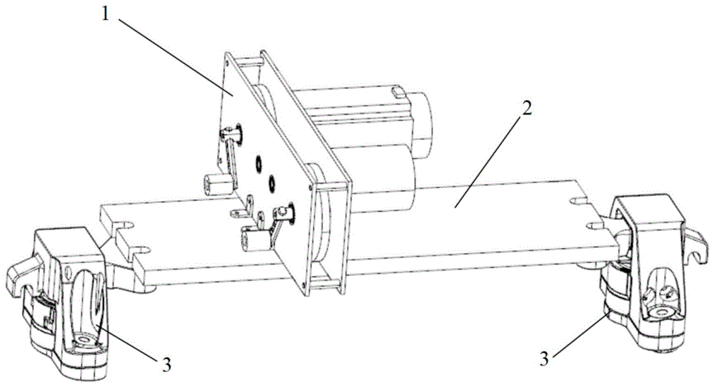
FIG. 1 is a schematic view of the overall structure of the present invention;
FIG. 2 is a schematic view of the structure of the excitation applying apparatus;
FIG. 3 is a schematic cross-sectional view of a gearbox;
FIG. 4 is a schematic structural view of a connecting rod and an excitation weight;
FIG. 5 is a schematic connection diagram of a motor speed regulating unit according to the present invention;
the notation in the figure is: 1 is an excitation applying device, 2 is a base, 3 is an active suspension assembly, 11 is a gear box, 12 is a motor, 13 is a generator, 14 is a connecting rod, 141 is a mounting hole, 15 is an excitation balancing weight, 111 is a first gear, 112 is a second gear, 113 is a third gear, 114 is a fourth gear, 115 is a first gear output shaft, 116 is a second gear output shaft, 117 is a third gear output shaft, and 118 is a fourth gear output shaft.
Detailed Description
The invention is described in detail below with reference to the figures and specific embodiments.
Examples
As shown in fig. 1, 2 and 3, a double active suspension test bench comprises an excitation applying device 1, a base 2 and an active suspension assembly 3, wherein the excitation applying device 1 is installed at the top of the base 2, the active suspension assembly 3 is installed at the bottom of two ends of the base 2, the excitation applying device 1 comprises a gear box 11, a motor 12, a generator 13, a connecting rod 14 and an excitation balancing weight 15, the gear box 11 comprises a first gear 111, a second gear 112, a third gear 113 and a fourth gear 114 which are meshed in sequence, each gear is provided with an output shaft, namely a first gear output shaft 115, a second gear output shaft 116, a third gear output shaft 117 and a fourth gear output shaft 118. The two connecting rods 14 are respectively connected with a first gear output shaft 115 and a fourth gear output shaft 118, the tail ends of the connecting rods 14 are provided with excitation balancing weights 15, the installation angles of the two connecting rods 14 are mutually symmetrical so as to offset the excitation force in the horizontal direction, and the installation position of the excitation applying device 1 deviates from the center of the base 2 and deviates to one side of the active suspension assembly 3 so as to generate torsional vibration excitation moment. The main shaft of the motor 12 is connected with a first gear output shaft 115, the main shaft of the generator 13 is connected with a third gear output shaft 117, the motor 12 drives the generator 13 to run at a high speed to do work outwards to adjust the rotating speed, when the motor 12 rotates, the four gears are driven to rotate, and the two excitation counter weights 12 rotate in opposite directions, so that unbalanced inertia force and moment are generated, and excitation of an actual in-line four-cylinder engine of the automobile is simulated.
In this embodiment, the four gears are all cylindrical gears, the first gear 111 and the fourth gear 114 have the same number of teeth and are large gears, and the second gear 112 and the third gear 113 have the same number of teeth and are small gears. The two connecting rods 14 are respectively and vertically connected with a first gear output shaft 115 and a fourth gear output shaft 118, the installation angles are symmetrical, and excitation balancing weights 15 with the same mass are respectively arranged at the tail ends of the two connecting rods 14. When the excitation applying device 1 works, the rotation directions of the two excitation balancing weights 15 are opposite, the rotation speeds of the two excitation balancing weights 15 are the same, and unbalanced inertial force generated by the excitation balancing weights 15 is synthesized to be vertical sinusoidal excitation force, so that the vertical excitation force of the in-line four-cylinder engine of the automobile can be simulated. The installation position of the excitation applying device 1 deviates from the center of the base 2 and is close to the active suspension assembly 3 on one side, so that the action position of the vertical excitation force deviates from the mass center of the rack, a force arm is formed, and the excitation of torsional vibration torque is generated, and the torsional vibration excitation torque of an in-line four-cylinder engine of an automobile can be simulated.
The connecting rod 14 and the excitation counter weight 15 are schematically shown in fig. 4, the connecting rod 14 is provided with a plurality of mounting holes 141, the excitation counter weight 15 can be mounted, the magnitude of the excitation force can be adjusted by adjusting the mass, the number and the mounting position of the excitation variety block 15, in addition, because the excitation applying device 1 is mounted at a position deviated from the center of the base 2, the vertical unbalanced inertia force generated by the two excitation counter weight 15 can generate torsional excitation torque, so as to simulate the excitation torque of an in-line four-cylinder engine of an automobile, the frequency of the torsional excitation torque is the same as that of the vertical unbalanced inertia force, and the magnitude of the torsional excitation torque can be adjusted by adjusting the mounting position of the excitation applying device 1 (namely, the distance of the excitation applying device 1 deviated from the center of the base 2).
Specifically, in the working process of the excitation applying device 1, the motor 12 drags the two connecting rods 14 to rotate through the gear box 11, the rotating surfaces of the two connecting rods 14 are in the same plane, the installation angles are symmetrical, the rotating directions are opposite, the two excitation counter weights 15 are respectively installed at the tail ends of the two connecting rods 14, the masses of the two excitation counter weights 15 are the same, unbalanced inertial forces generated by the two excitation counter weights 15 are offset in the horizontal direction and overlapped in the vertical direction, a vertical excitation force can be generated to simulate the vertical excitation of an automobile engine, and then the masses of the two excitation counter weights 15 are adjusted, so that the magnitude of the vertical excitation force can be adjusted.
Because the excitation frequency of the in-line four-cylinder engine is twice of the rotating frequency, and the excitation frequency of the in-line four-cylinder engine is twice of the rotating frequency, the invention needs to pay attention to the conversion between the rotating speed of the motor and the rotating speed of the simulated automobile engine in the actual use process. For example: if the working condition of 1000 revolutions per minute of the automobile engine needs to be simulated, the rotating speed of the motor needs to be adjusted to 2000 revolutions per minute.
In this embodiment, the two active suspension assemblies 3 are symmetrically installed at the bottom of the two ends of the base 2, the installation direction is consistent with the axial direction of the gear box 11, the support reaction force and the couple moment generated by the two active suspension assemblies 3 are consistent with the vertical excitation force and the torsional excitation moment generated by the excitation applying device 1, and an efficient active vibration damping test can be performed.
In the test bench provided by the invention, the generator 13 is connected with a motor rotating speed adjusting unit, as shown in fig. 5, the motor rotating speed adjusting unit is constructed by adopting a plurality of variable resistors 131 which are connected in parallel, because the motor 12 usually adopts a squirrel-cage type three-phase asynchronous motor with low cost, generally 50Hz three-phase alternating current is used as a power supply, the rotating speed is usually constant under the no-load working condition, if the speed is required to be adjusted, a frequency converter is required to be used for converting the alternating current into direct current, and then the direct current is converted into alternating current with a certain frequency, so that the cost of the bench is high, and the operation is complex. In the invention, the motor 12 drags the generator 13 to do work outwards through the gear box 11, the energy output outwards is dissipated by the variable resistor 131, the rotating speed of the motor 12 can be conveniently adjusted only through the resistance value and the number of the variable resistor 131 at the load end, and different rotating speed working conditions of the automobile engine can be simulated.
The motor 12 is connected with the low-speed shaft of the gear box 11, the generator 13 is connected with the high-speed shaft of the gear box 11, the rotating speed of the generator 13 can be increased, the output voltage is further increased, the coil current of the generator 13 is reduced, current overload is avoided, and the reliable work of the excitation applying device 1 is ensured.
In this embodiment, some counter weights can be arranged on the base 2 according to actual conditions, so that the active suspension 3 is subjected to sufficient preload and the center of mass position and the inertial parameters of the gantry are adjusted. It is also possible to replace one of the active suspensions 3 with a normal rubber suspension or a hydraulic suspension for a single active suspension test.
In this embodiment, the motor 12 is specifically an asynchronous motor, and the generator 13 is a dc generator, and in practical application, the motor 12 may be changed into a synchronous motor or a dc motor, and the generator 13 may be changed into an ac generator.
In conclusion, the invention can simultaneously generate vertical exciting force and torsional vibration exciting torque with the same frequency, is consistent with the exciting form of an in-line four-cylinder engine of an automobile, can simulate the working environments of two active suspensions, indirectly adjusts the rotating speed by adjusting the number and the resistance value of the load resistor of the generator, can simulate the working conditions with different rotating speeds, and also has lower cost and simpler and more convenient use.