CN112127390A - Construction process for simply plugging outer wall reserved sleeve in underground structural area - Google Patents
Construction process for simply plugging outer wall reserved sleeve in underground structural area Download PDFInfo
- Publication number
- CN112127390A CN112127390A CN202010915275.3A CN202010915275A CN112127390A CN 112127390 A CN112127390 A CN 112127390A CN 202010915275 A CN202010915275 A CN 202010915275A CN 112127390 A CN112127390 A CN 112127390A
- Authority
- CN
- China
- Prior art keywords
- waterproof
- layer
- sleeve
- wall
- reinforcing steel
- Prior art date
- Legal status (The legal status is an assumption and is not a legal conclusion. Google has not performed a legal analysis and makes no representation as to the accuracy of the status listed.)
- Pending
Links
- 238000010276 construction Methods 0.000 title claims abstract description 44
- 238000000034 method Methods 0.000 title claims abstract description 16
- 239000010410 layer Substances 0.000 claims abstract description 81
- 239000000463 material Substances 0.000 claims abstract description 25
- XLYOFNOQVPJJNP-UHFFFAOYSA-N water Substances O XLYOFNOQVPJJNP-UHFFFAOYSA-N 0.000 claims abstract description 20
- 239000011241 protective layer Substances 0.000 claims abstract description 8
- 229910001294 Reinforcing steel Inorganic materials 0.000 claims description 40
- 229910000831 Steel Inorganic materials 0.000 claims description 40
- 239000010959 steel Substances 0.000 claims description 40
- 230000003014 reinforcing effect Effects 0.000 claims description 28
- XEEYBQQBJWHFJM-UHFFFAOYSA-N Iron Chemical compound [Fe] XEEYBQQBJWHFJM-UHFFFAOYSA-N 0.000 claims description 18
- 238000009415 formwork Methods 0.000 claims description 16
- 229910052742 iron Inorganic materials 0.000 claims description 9
- 238000009412 basement excavation Methods 0.000 claims description 8
- 238000004140 cleaning Methods 0.000 claims description 6
- 238000005520 cutting process Methods 0.000 claims description 6
- 238000013461 design Methods 0.000 claims description 6
- 238000012423 maintenance Methods 0.000 claims description 6
- 238000004519 manufacturing process Methods 0.000 claims description 6
- 238000005096 rolling process Methods 0.000 claims description 6
- 239000002689 soil Substances 0.000 claims description 6
- 230000007547 defect Effects 0.000 claims description 4
- 238000003825 pressing Methods 0.000 claims description 3
- 238000010408 sweeping Methods 0.000 claims description 3
- 238000012360 testing method Methods 0.000 claims description 3
- 230000007306 turnover Effects 0.000 claims description 3
- 238000003466 welding Methods 0.000 claims description 3
- 238000005516 engineering process Methods 0.000 claims description 2
- 230000000149 penetrating effect Effects 0.000 claims description 2
- 238000007789 sealing Methods 0.000 claims description 2
- 239000003337 fertilizer Substances 0.000 abstract description 7
- 239000000945 filler Substances 0.000 abstract 1
- 230000008520 organization Effects 0.000 abstract 1
- 238000009434 installation Methods 0.000 description 7
- 239000012528 membrane Substances 0.000 description 4
- 238000004078 waterproofing Methods 0.000 description 4
- 239000007779 soft material Substances 0.000 description 3
- 239000004568 cement Substances 0.000 description 2
- 238000010586 diagram Methods 0.000 description 2
- 230000002787 reinforcement Effects 0.000 description 2
- 229920000742 Cotton Polymers 0.000 description 1
- 238000009435 building construction Methods 0.000 description 1
- 238000007796 conventional method Methods 0.000 description 1
- 238000011161 development Methods 0.000 description 1
- 230000007613 environmental effect Effects 0.000 description 1
- 238000007689 inspection Methods 0.000 description 1
- 230000001681 protective effect Effects 0.000 description 1
- 238000011144 upstream manufacturing Methods 0.000 description 1
Images


Classifications
-
- E—FIXED CONSTRUCTIONS
- E02—HYDRAULIC ENGINEERING; FOUNDATIONS; SOIL SHIFTING
- E02D—FOUNDATIONS; EXCAVATIONS; EMBANKMENTS; UNDERGROUND OR UNDERWATER STRUCTURES
- E02D29/00—Independent underground or underwater structures; Retaining walls
- E02D29/16—Arrangement or construction of joints in foundation structures
-
- E—FIXED CONSTRUCTIONS
- E02—HYDRAULIC ENGINEERING; FOUNDATIONS; SOIL SHIFTING
- E02D—FOUNDATIONS; EXCAVATIONS; EMBANKMENTS; UNDERGROUND OR UNDERWATER STRUCTURES
- E02D31/00—Protective arrangements for foundations or foundation structures; Ground foundation measures for protecting the soil or the subsoil water, e.g. preventing or counteracting oil pollution
- E02D31/02—Protective arrangements for foundations or foundation structures; Ground foundation measures for protecting the soil or the subsoil water, e.g. preventing or counteracting oil pollution against ground humidity or ground water
Landscapes
- Engineering & Computer Science (AREA)
- Life Sciences & Earth Sciences (AREA)
- Environmental & Geological Engineering (AREA)
- General Life Sciences & Earth Sciences (AREA)
- Mining & Mineral Resources (AREA)
- Paleontology (AREA)
- Civil Engineering (AREA)
- General Engineering & Computer Science (AREA)
- Structural Engineering (AREA)
- Hydrology & Water Resources (AREA)
- Underground Structures, Protecting, Testing And Restoring Foundations (AREA)
Abstract
The invention discloses a construction process for simply plugging a reserved sleeve of an outer wall in an underground structural area, which comprises the following steps of firstly completing an outer wall column and a reserved sleeve in the underground structural area; and railings and baffles are respectively arranged inside and outside the reserved sleeve, and then the railings and the baffles on the inner side and the outer side of the embedded sleeve are fixed through the tie rods. After the baffle is fixed, a waterproof layer is added on the outer side of the baffle. And finally, backfilling and tamping according to the conventional organization waterproof protective layer and earthwork in a layered manner. When the pipeline is connected with the inside and outside of the underground structure, the water stopping filler is embedded and filled between the outer wall of the connecting pipe and the inner wall of the sleeve. The invention solves the problem that mud rain leaks into the underground structure after the earth of the fertilizer tank is backfilled, and achieves the purposes of convenient construction, material saving and labor consumption reduction.
Description
Technical Field
The invention relates to a construction process for simply plugging an outer wall reserved sleeve in an underground structural area, in particular to a construction process for simply plugging an outer wall reserved sleeve in an underground structural area.
Background
With the continuous development of building construction technology, the space for underground needs becomes a normal state. The outer wall plate of the underground structure is often penetrated by a pipeline, so that the connection between the inner pipeline and the outer pipeline of the underground structure is realized; but the pipeline installation is far behind the works of earth backfill and the like outside the underground structure.
In order to improve the operation environment of structure construction, the backfilling of the foundation pit fertilizer groove earthwork is usually carried out after the construction of an underground structure is finished; when the pipeline outside the underground structure is installed, excavation of pipeline groove earthwork, installation of the pipeline and the like are sequentially carried out. And finally, backfilling earthwork of the pipeline groove after the pipeline is installed and qualified by inspection and acceptance. In order to solve the problem that the backfilling of the fertilizer groove earthwork is restricted due to the fact that a sleeve is reserved on an external wall plate in an underground structural area, the sleeve is filled with cement, cotton neps and the like to be used for temporary plugging. Due to the characteristics of cement, neps and the like and the objective existence of gaps in the sleeve, rain and mud leakage often occurs; the existence of rain and mud leakage inevitably affects the working environment and construction conditions inside the underground structure; therefore, a convenient and practical construction method for simply plugging the underground structural wallboard sleeve is urgently needed in a construction site.
When the underground structure construction is completed according to the conventional method, various reserved sleeves with different numbers, specifications and heights are inevitably arranged on the outer wall column wall of the underground structure. The existence of the reserved sleeve pipe enables the inside and the outside of the underground structure to be communicated with each other, and installation of various pipelines in the later period is facilitated.
The existence of the reserved sleeve inevitably influences the backfilling of the foundation pit earthwork of the fertilizer groove (namely, when the backfilling standard of the foundation pit earthwork is higher than the elevation of the reserved sleeve, silt and water can be continuously introduced into the underground structure according to the principle that water flows to the lower part). In view of the temporary property of the reserve pipe, the reserve pipe is usually filled with concrete or soft material. Because the characteristics of concrete or soft materials and the like limit, the concrete or soft materials can not be well and closely combined with the reserved casing pipe, and the phenomenon that mud, rain and rain leak into the underground structure along the defect position between the walls of the reserved casing pipe still occurs.
Disclosure of Invention
The invention aims to provide a construction process for simply plugging a reserved sleeve of an outer wall in an underground structural area.
The technical scheme adopted by the invention is as follows:
the invention relates to a construction process for simply plugging a reserved sleeve of an outer wall in an underground structural area, which comprises the following steps of:
the method comprises the following steps: sequentially finishing excavation of foundation pit earthwork according to a construction rule of an underground structure, forming a marking height line and a side slope control line at the bottom of the foundation pit, sequentially finishing pouring of a concrete cushion layer, laying of a waterproof layer below a raft plate and binding of reinforcing steel bars of the raft plate, marking the position of an external wall column on the reinforcing steel bars of the raft plate, and pre-inserting vertical reinforcing steel bars of an inner layer reinforcing mesh sheet and vertical reinforcing steel bars of an outer layer reinforcing mesh sheet of a planar external wall plate on a guide wall at the marked position of the external wall column; an outer wall column construction joint is arranged on the upper plane of the raft plate, and an outer wall column below the construction joint is a guide wall; a split bolt with a water stop wing ring is arranged on the guide wall, and a water stop steel plate is arranged in the middle of the upper plane of the guide wall; the underground structure is divided into an inner area and an outer area by the outer wall columns; arranging a waterproof protective layer on the concrete cushion layer beyond the range of the raft and the waterproof layer paved on the concrete cushion layer; connecting vertical reinforcing steel bar inner-row ribs to vertical reinforcing steel bars of an inner reinforcing steel bar mesh of an outer wall plate in sequence to form inner-row vertical reinforcing steel bars, connecting vertical reinforcing steel bar outer-row ribs to vertical reinforcing steel bars of an outer reinforcing steel bar mesh in sequence to form outer-row vertical reinforcing steel bars, installing horizontal inward reinforcing steel bar ribs outside the inner-row vertical reinforcing steel bars, and horizontally outward reinforcing steel bar outer-row ribs outside the outer-row vertical reinforcing steel bars to form a double-layer reinforcing steel bar mesh of an outer wall column, installing ladder ribs and drag ribs inside the double-layer reinforcing steel bar mesh, and installing protective cushion blocks on the reinforcing steel;
step two: cutting a reserved sleeve meeting design requirements according to a design drawing, welding a water stop wing ring on the reserved sleeve to manufacture a complete waterproof steel sleeve, and then pre-embedding and fixing the waterproof reserved sleeve on a double-layer reinforcing mesh sheet of the outer wall column according to the size shown in the drawing;
step three: binding the steel bar framework, and carrying out die assembly operation after supervision and acceptance; when the die is closed, a split bolt with a water stop wing ring is required to be arranged on the double-layer reinforcing mesh sheet; then a template, a template back ridge and a double-steel-pipe keel are sequentially erected outside the double-layer reinforcing mesh, a mountain-shaped clamp is arranged on the double-steel-pipe keel, a nut is installed on a split bolt, and the template of an outer wall column in the underground structural area is tensioned;
step four: erecting a complete formwork support frame by utilizing scaffold pipes and auxiliary parts in the range of an underground structure, wherein the formwork support frame comprises a formwork support frame upright rod, a horizontal rod and a floor sweeping rod; the keel, the back ridge and the template are sequentially laid on the upper portion of the template support frame to form a platform beam-slab bottom template system, and the platform beam-slab bottom template system comprises the keel, the back ridge and the template. Binding the platform beam plate reinforcing steel bars;
step five: completing concrete pouring of the external wall column of the underground structure according to the requirements of the operation regulations;
step six: finishing the maintenance of the concrete of the underground structure external wall column according to the requirement of concrete construction specifications; after maintenance is finished, according to the sequence of first supporting, then detaching and then detaching, firstly loosening nuts of the split bolts, detaching double steel pipe keels of the vertical structure, template back ridges and templates, then detaching the platform beam plate bottom die system and the template support frame, and cleaning, piling and moving detached turnover materials out of a working surface;
step seven: cleaning the structural surface of the external wall column in the underground structural area, and repairing the defect; removing the waterproof protective layer, and rolling up the originally thrown (reserved) lower waterproof layer of the raft;
step eight: manufacturing a special fixing frame for the reserved sleeve; the fixing frame is provided with a wooden baffle plate with the outer diameter larger than the outer diameter of the sleeve by 200 mm, an iron pull rod is fixed on the baffle plate, and an iron railing is arranged at the end part of the iron pull rod;
step nine: performing waterproof layer construction according to the requirements of waterproof operation regulations; rolling the waterproof layer into the reserved sleeve to form the waterproof layer in the reserved sleeve;
step ten: the special mount (wooden plate washer, railing, pull rod) of sleeve pipe position is reserved in the installation, notices: the waterproof layer cannot be damaged when the special fixing frame is installed; one end of the fixing frame is provided with a wooden baffle which is contacted with the waterproof material to ensure that the waterproof material is not damaged.
Step eleven: waterproof coiled materials are added on the baffle side of the special fixing frame at the position of the reserved sleeve and are connected with the waterproof layer;
step twelve: according to the requirement of foundation pit earthwork backfilling, backfilling earthwork layer by layer and tamping until reaching the designed elevation;
step thirteen: before the pipeline construction outside the underground structure range, trench earthwork excavation is carried out according to the water stop wing ring and the pre-buried position of the reserved sleeve, the pipe orifice position of the reserved sleeve is exposed, and the waterproof coiled material is cleaned;
fourteen steps: the convex part of the waterproof coiled material is marked into a cross line, and the waterproof coiled material is slightly torn until the requirement of taking out the baffle plate is met;
step fifteen: the connection between the pull rod and the railing inside the underground structure is released, and the baffle of the special fixing frame for the reserved sleeve is taken out;
sixthly, the steps are as follows: cutting off redundant waterproof coiled materials;
seventeen steps: installing a connecting pipe in a waterproof reserved sleeve penetrating through the outer wall surface in the underground structural area according to the operation rules; and waterproof sealing treatment is carried out;
eighteen steps: and completing external connection of pipelines and the like, and backfilling the trench soil according to the operation specification requirements after the trench soil is qualified through a pressing test.
The invention has the advantages that: the wooden baffle plate is fixed on the water-facing side of the pre-buried sleeve through the pull rod and the steel railing (arranged on the water-facing side of the pre-buried sleeve), and a waterproof layer is added on the outer side of the baffle plate (the waterproof layer is welded with a large-area waterproof layer of an outer wall column wall in an underground structure area to form a complete underground building). After the reserved sleeve on the outer wall column is plugged in such a way, the problem that mud rain leaks into the underground structure after the earthwork of the fertilizer groove is backfilled is thoroughly solved; meanwhile, when the later-stage connecting pipeline is constructed, due to the outer convex baffle plates and the waterproof layers, large-area waterproof damage to the outer side of the underground structure when the pipeline groove is excavated is avoided. On the basis of finishing an underground structure and a waterproof sleeve according to a conventional construction method, a baffle plate, a railing and a pull rod for connecting the baffle plate and the railing are respectively arranged on the upstream side and the downstream side of a reserved sleeve, and a waterproof layer is added on the outer side of the baffle plate (the waterproof layer is connected with a large-area waterproof layer of a wall column wall of the underground structure to form a complete underground structure (structure) building). The method not only solves the problem of backfilling the earthwork of the fertilizer groove, but also protects the waterproof layer of the outer wall column wall in the underground structure area when the connecting pipeline is used for communicating the earthwork to excavate at the later stage, thereby realizing the purposes of facilitating construction, saving materials and reducing labor consumption and really reflecting the requirement of environmental protection.
Drawings
Fig. 1 is a schematic structural view of basement raft construction.
Fig. 2 is a structural schematic diagram of the basement exterior wall column reinforcement construction of the invention.
Fig. 3 is a schematic structural view of the construction of the outer wall columns and the platform beam plates in the underground structural area.
Fig. 4 is a schematic view of an outer wall column and a platform beam slab concrete structure in an underground structural region according to the present invention.
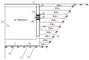
Fig. 5 is a schematic diagram of a temporary plugging structure installed at the position of an external wall reserved pipe in an underground structural area.
FIG. 6 is a schematic view of the earth backfill hierarchy at the outer side of the outer wall in the subterranean zone of the present invention.
FIG. 7 is a schematic view of earth excavation at a position where a pipe needs to be connected on the outer side of an outer wall in an underground structural region.
Fig. 8 is a schematic view of the communicating installation structure of the external and internal pipelines of the external wall in the underground structural region.
Fig. 9 is a schematic view of the communicating installation structure of the external and internal pipelines of the external wall in the underground structural region.
Wherein: 1. the method comprises the following steps of (1) marking a height line at the bottom of a foundation pit, 2) concrete cushion layer, 3, raft plate, 4, side slope control line, 5, split bolts, 6, water stop steel plate, 7, vertical steel bar inner row ribs, 71, vertical steel bars of outer wall plate inner layer steel bar net sheets, 8, vertical steel bar outer row ribs, 81, vertical steel bars of outer layer steel bar net sheets, 9, horizontal steel bar outer row ribs, 10, horizontal steel bar inner row ribs, 11 and water stop wing rings; 12. the prefabricated building comprises reserved sleeves, 13, a template support frame, 14, a platform beam slab bottom die system, 15, template back ridges, 16, a template, 17, double steel pipe keels, 18, a mountain-shaped clamp, 19, a waterproof layer, 191, a waterproof coiled material, 20, a steel sleeve waterproof layer, 21, a raft lower waterproof layer, 22, a waterproof protective layer, 23, a baffle, 24, a railing, 25, a pull rod, 26, a connecting pipe, 27, a waterproof material, 28, a guide wall, 29 and an outer wall column.
Detailed Description
As shown in fig. 1-9, the invention relates to a construction process for simply plugging a reserved sleeve of an outer wall in an underground structural area, which comprises the following steps:
the method comprises the following steps: and (3) sequentially finishing excavation of the foundation pit earthwork according to the construction rule of the underground structure to form a foundation pit bottom elevation line 1 and a side slope control line 4, and sequentially finishing pouring of a concrete cushion layer 2, laying of a raft lower waterproof layer 21 and binding of concrete steel bars of a raft 3. According to the design, the position of the external wall column 29 is calibrated on the steel bars of the raft 3, the vertical steel bars 71 of the internal layer steel bar mesh and the vertical steel bars 81 of the external layer steel bar mesh of the external wall plate are pre-inserted in the calibrated position of the external wall column 29, and an external wall column construction joint is arranged at the height of 450 mm from the upper plane of the raft 3. The outer wall column 29 below the construction joint is a guide wall 28. The distance between the upper plane of the guide wall 28 and the upper plane of the raft plate 3 is 450 mm, a split bolt 5 with a water stop wing ring is arranged on the outer wall column formwork at the position, 200 mm away from the surface of the raft, of the upper plane of the guide wall 28, and the guide wall formwork, namely the outer wall column formwork, is reinforced. And a water stop steel plate 6 is installed in the middle of a construction joint (namely the upper plane of the guide wall). The guide wall divides the underground structure into an inner area and an outer area; after the raft and the guide wall concrete are poured, throwing out (pre-inserting the upper plane of the guide wall) the vertical steel bars 71 of the inner layer steel bar meshes and the vertical steel bars 81 of the outer layer steel bar meshes of the external wall plate; in order to protect the lower waterproof layer 21 of the raft, a waterproof protective layer 22 is arranged on the concrete cushion layer 2 beyond the range of the raft 3 and the waterproof layer 21 paved on the concrete cushion layer; vertical reinforcing bars 71 of an inner reinforcing bar mesh of an outer wall plate are respectively connected with vertical reinforcing bars in an inner row of ribs 7 to form inner vertical reinforcing bars, vertical reinforcing bars 81 of the outer reinforcing bar mesh are connected with vertical reinforcing bar outer rows of ribs 8 to form tight outer vertical reinforcing bars, horizontal ribs 10 are arranged in the reinforcing bars on the outer side (close to the basement) of the inner vertical reinforcing bars, horizontal ribs 9 are arranged in the reinforcing bars on the outer side (far from the basement) of the outer vertical reinforcing bars, a double-layer reinforcing bar mesh of an outer wall column is formed, ladder ribs and drag hook ribs are arranged in the double-layer reinforcing bar mesh, and a protection cushion block is arranged on the reinforcing. The wall column is from advantage of 450 mm construction joints of raft face: a. a water-stop steel plate strip of-3 x 300 mm is usually designed at the joint of wall column concrete (namely, the 150 mm water-stop steel plate strip is embedded in the firstly-poured concrete, and the 150 mm water-stop steel plate strip is also embedded in the later-poured concrete), so that water-stop facilities are convenient to install; b. in a construction site, a large number of 915 x 1830 mm templates are used, and the template is subjected to center dividing and cutting on the 915 mm side to form two 457.5 x 1830 mm templates, so that the utilization efficiency is highest; c. the distance between the water stop steel plate strip and the surface of the raft is 300 mm, so that the reinforcement requirement after the guide wall template is installed is facilitated.
Step two: cutting a reserved sleeve 12 meeting design requirements according to a design drawing, welding a water stop wing ring 11 on the reserved sleeve 12 to manufacture a complete waterproof steel sleeve, and embedding and fixing the waterproof reserved sleeve 12 on a double-layer reinforcing mesh of the outer wall column according to the size shown in the drawing.
Step three: binding the steel bar framework, and carrying out die assembly operation after supervision and acceptance; when the die is closed, a split bolt 5 with a water stop wing ring is required to be arranged on the double-layer reinforcing mesh; and then the template 16, the template back ridge 15 and the double steel pipe keel 17 are sequentially erected on the outer side of the double-layer reinforcing mesh, a mountain-shaped clamp 18 is arranged on the double steel pipe keel 17, a nut is installed on the split bolt 5, and the template of the outer wall column in the underground structure area is tensioned.
Step four: a complete formwork support frame 13 is erected in the range of an underground structure by utilizing scaffold pipes and auxiliary parts, and the formwork support frame 13 comprises a formwork support frame upright rod, a horizontal rod and a floor sweeping rod. The upper part of the formwork support frame is sequentially paved with a keel, a back ridge and a formwork to form a finished platform beam plate bottom formwork system 14, and the platform beam plate bottom formwork system 14 comprises the keel, the back ridge and the formwork; and binding the platform beam plate reinforcing steel bars.
Step five: and (5) completing concrete pouring of the external wall column of the underground structure according to the requirements of the operation regulations.
Step six: finishing the maintenance of the concrete of the underground structure external wall column according to the requirement of concrete construction specifications; after the maintenance is finished, according to the sequence of firstly supporting and then dismounting, and then firstly dismounting, firstly loosening the nuts of the split bolts, dismounting the double-steel-pipe keel 17, the template back edge 15 and the template 16 of the vertical structure, then dismounting the platform beam plate bottom die system 14 and the template support frame 13, and cleaning, piling and moving out the dismounted turnover materials from the working surface.
Step seven: cleaning the structural surface of the external wall column in the underground structural area, and repairing the defect; removing the waterproof protective layer 22, and rolling up the originally thrown (reserved) lower raft waterproof layer 21;
step eight: manufacturing a special fixing frame for the reserved sleeve 12; the fixing frame is provided with a wooden baffle plate 23 which is larger than the outer diameter of the sleeve by 200 mm and can be used as long as the numerical value is more than 200 mm, an iron pull rod 25 is fixed on the baffle plate 23, and an iron railing 24 is arranged at the end part of the iron pull rod 25.
Step nine: constructing a waterproof layer 19 according to the requirements of waterproof operation regulations; and the waterproof layer 19 is rolled into the reserved sleeve to form the waterproof layer 20 in the reserved sleeve, so that the waterproof quality is ensured.
Step ten: the special mount of the sleeve pipe 12 position is reserved in the installation, wooden plate washer 23, railing 24, pull rod 25 promptly, notice: the waterproof layer 19 cannot be damaged when the special fixing frame is installed; one end of the fixing frame is provided with a wooden baffle, the wooden baffle is contacted with the waterproof material, the waterproof material can be ensured not to be damaged, and certainly, when the special fixing frame is firm, the special fixing frame is applied with proper force and is not loosened after being installed.
Step eleven: and a waterproof coiled material 191 is added on the baffle side of the special fixing frame at the position of the reserved sleeve 12 and is connected with a waterproof layer 19.
Step twelve: and backfilling and tamping earthwork layer by layer according to the requirement of backfilling earthwork of the foundation pit until the earthwork reaches the designed elevation.
Step thirteen: before the pipeline construction outside the underground structure scope, carry out slot earthwork excavation according to stagnant water wing ring 11, the pre-buried position of reservation sleeve pipe 12, expose the mouth of pipe position of reservation sleeve pipe 12 to clear up to waterproofing membrane 191.
Fourteen steps: in the convex portion of waterproofing membrane 191, a cross line is drawn, and waterproofing membrane 191 is torn slightly until the need for taking out baffle plate 23 is satisfied.
Step fifteen: the connection between the pull rod 25 and the railing 24 inside the underground structure is released, and the baffle 23 of the special fixing frame for the reserved sleeve is taken out.
Sixthly, the steps are as follows: excess waterproofing membrane 191 is cut away.
Seventeen steps: according to the operation rules, a connecting pipe 26 of a waterproof casing pipe for communicating an underground structure inner pipeline and a municipal pipeline is installed and penetrates through the outer wall surface in the underground structure area, and a waterproof material 27 is arranged at the gap between the inner wall of the reserved casing pipe 12 and the outer wall of the connecting pipe 26 for embedding and filling, so that the leakage of the external part of the pipeline is avoided.
Eighteen steps: and completing external connection of pipelines and the like, and backfilling the trench soil according to the operation specification requirements after the trench soil is qualified through a pressing test.
The invention not only solves the requirement of backfilling the earthwork of the fertilizer groove after the basement structure is finished, but also prevents backfilled earthwork outside the underground structure, rainwater and the like from leaking into the room; meanwhile, the problem that the waterproof layer of the outer wall column wall in the underground structure area is possibly damaged during the earthwork construction of the connecting pipeline groove in the later period can be solved, the construction is convenient, the material is saved, the labor consumption is reduced, the cost is reduced, and the quality is ensured.
Claims (3)
1. The utility model provides a construction technology of simple and easy shutoff of outer wall reservation sleeve pipe in underground structure district which characterized in that:
the method comprises the following steps:
the method comprises the following steps: sequentially finishing excavation of foundation pit earthwork according to a construction rule of an underground structure to form a foundation pit bottom elevation line (1) and a side slope control line (4), sequentially finishing pouring of a concrete cushion layer (2), laying of a raft lower waterproof layer (21) and binding of reinforcing steel bars of a raft (3), marking the position of an external wall column (29) on the reinforcing steel bars of the raft (3), and pre-inserting vertical reinforcing steel bars (71) of an inner layer reinforcing mesh sheet and vertical reinforcing steel bars (81) of an outer layer reinforcing mesh sheet of a planar external wall plate on a guide wall at the marked position of the external wall column; an outer wall column construction joint is arranged on the upper plane of the raft plate (3), and an outer wall column (29) below the construction joint is a guide wall (28); a split bolt (5) with a water stop wing ring is arranged on the guide wall (28), and a water stop steel plate (6) is vertically arranged in the middle of the upper plane of the guide wall; the underground structure is divided into an inner area and an outer area by the outer wall columns; arranging a waterproof protective layer (22) on the concrete cushion layer (2) beyond the range of the raft (3) and the waterproof layer (21) paved on the concrete cushion layer; vertical reinforcing steel bar inner row ribs (7) are sequentially connected to vertical reinforcing steel bars (71) of an outer wall panel inner reinforcing steel bar mesh to form inner row vertical reinforcing steel bars, vertical reinforcing steel bar outer row ribs (8) are sequentially connected to vertical reinforcing steel bars (81) of an outer reinforcing steel bar mesh to form outer row vertical reinforcing steel bars, horizontal reinforcing steel bar inner row ribs (10) are installed on the outer sides of the inner row vertical reinforcing steel bars, horizontal reinforcing steel bar outer row ribs (9) are installed on the outer sides of the outer row vertical reinforcing steel bars to form a double-layer reinforcing steel bar mesh of an outer wall column, ladder ribs and drag hook ribs are installed inside the double-layer reinforcing steel bar mesh, and;
step two: cutting a reserved sleeve (12) according to a design drawing, welding a water stop wing ring (11) on the reserved sleeve (12) to manufacture a complete waterproof steel sleeve, and then pre-burying and fixing the waterproof reserved sleeve (12) on a double-layer reinforcing mesh sheet of the outer wall column according to the size shown in the drawing;
step three: binding the steel bar framework, and carrying out die assembly operation after supervision and acceptance; when the die is closed, a split bolt (5) with a water stop wing ring is required to be arranged on the double-layer reinforcing mesh sheet; a template (16), a template back edge (15) and a double-steel-pipe keel (17) are sequentially erected outside the double-layer reinforcing mesh, a mountain-shaped clamp (18) is arranged on the double-steel-pipe keel (17), a nut is installed on the split bolt (5), and the template of the outer wall column in the underground structural area is tensioned;
step four: erecting a complete formwork support frame (13) in the range of an underground structure by utilizing scaffold tubes and auxiliary parts (the parts 13 are the combination of formwork support frame upright rods, horizontal rods and sweeping rods); a keel, a back edge and a template are sequentially paved on the upper part of the template support frame to form a finished platform beam plate bottom template system (14); binding the platform beam plate reinforcing steel bars;
step five: completing concrete pouring of the external wall column of the underground structure according to the requirements of the operation regulations;
step six: finishing the maintenance of the concrete of the underground structure external wall column according to the requirement of concrete construction specifications; after maintenance is finished, according to the sequence of first support, then disassembly and then first disassembly, firstly loosening nuts of the split bolts, disassembling the double steel pipe keels (17) of the vertical structure, the template back edges (15) and the templates (16), then disassembling the platform beam plate bottom die system (14) and the template support frames (13), and cleaning, stacking and moving the disassembled turnover materials out of a working face;
step seven: cleaning the structural surface of the external wall column in the underground structural area, and repairing the defect; removing the waterproof protective layer (22), and rolling up the originally reserved lower raft waterproof layer (21);
step eight: manufacturing a special fixing frame for the reserved sleeve (12); the fixing frame is provided with a wooden baffle plate (23) with the outer diameter larger than the sleeve pipe by 200 mm, an iron pull rod (25) is fixed on the baffle plate (23), and an iron railing (24) is arranged at the end part of the iron pull rod (25);
step nine: constructing a waterproof layer (19) according to the requirements of waterproof operation regulations; rolling the waterproof layer into the reserved sleeve to form a waterproof layer 20 in the reserved sleeve;
step ten: a special fixing frame (a wooden baffle plate 23, a railing 24 and a pull rod 25) at the position of the reserved sleeve (12) is installed, and the waterproof layer (19) cannot be damaged when the special fixing frame is installed;
step eleven: a waterproof coiled material (191) is added on the baffle side of the special fixing frame at the position of the reserved sleeve (12) and is connected with a waterproof layer (19);
step twelve: according to the requirement of foundation pit earthwork backfilling, backfilling earthwork layer by layer and tamping until reaching the designed elevation;
step thirteen: before the pipeline construction outside the underground structure range, trench earth excavation is carried out according to the pre-buried positions of the water-stopping wing ring (11) and the reserved sleeve (12), the position of a pipe orifice of the reserved sleeve (12) is exposed, and the water-stopping wing ring is cleaned to the waterproof coiled material (191);
fourteen steps: the convex part of the waterproof coiled material (191) is marked into a cross line, and the waterproof coiled material (191) is slightly torn off until the requirement of taking out the baffle plate (23) is met;
step fifteen: the connection between a pull rod (25) and a railing (24) at the inner side of the underground structure is loosened, and a baffle plate (23) of a special fixing frame for reserving the sleeve is taken out;
sixthly, the steps are as follows: cutting off redundant waterproof coiled materials (191);
seventeen steps: installing a connecting pipe (26) in the waterproof reserved casing pipe (12) penetrating through the outer wall surface in the underground structural area according to the operation rules; and waterproof sealing treatment is carried out;
eighteen steps: and completing external connection of pipelines and the like, and backfilling the trench soil according to the operation specification requirements after the trench soil is qualified through a pressing test.
2. The construction process for simply plugging the outer wall reserved sleeve in the underground structural area according to claim 1, characterized by comprising the following steps: and step nine, rolling the waterproof layer (19) into the reserved sleeve (12) to form the waterproof layer (20) in the steel sleeve.
3. The construction process for simply plugging the outer wall reserved sleeve in the underground structural area according to claim 1, characterized by comprising the following steps: in the seventeenth step, a waterproof material (27) is arranged at the gap between the inner wall of the reserved sleeve (12) and the outer wall of the connecting pipe (26).
Priority Applications (1)
| Application Number | Priority Date | Filing Date | Title |
|---|---|---|---|
| CN202010915275.3A CN112127390A (en) | 2020-09-03 | 2020-09-03 | Construction process for simply plugging outer wall reserved sleeve in underground structural area |
Applications Claiming Priority (1)
| Application Number | Priority Date | Filing Date | Title |
|---|---|---|---|
| CN202010915275.3A CN112127390A (en) | 2020-09-03 | 2020-09-03 | Construction process for simply plugging outer wall reserved sleeve in underground structural area |
Publications (1)
| Publication Number | Publication Date |
|---|---|
| CN112127390A true CN112127390A (en) | 2020-12-25 |
Family
ID=73848814
Family Applications (1)
| Application Number | Title | Priority Date | Filing Date |
|---|---|---|---|
| CN202010915275.3A Pending CN112127390A (en) | 2020-09-03 | 2020-09-03 | Construction process for simply plugging outer wall reserved sleeve in underground structural area |
Country Status (1)
| Country | Link |
|---|---|
| CN (1) | CN112127390A (en) |
Cited By (2)
| Publication number | Priority date | Publication date | Assignee | Title |
|---|---|---|---|---|
| CN113585292A (en) * | 2021-08-25 | 2021-11-02 | 江苏南通三建集团股份有限公司 | Construction process for preventing underground structure from floating when earth is backfilled |
| CN113653104A (en) * | 2021-08-25 | 2021-11-16 | 中国建筑第八工程局有限公司 | Waterproof structure at underground wall and construction method thereof |
Citations (7)
| Publication number | Priority date | Publication date | Assignee | Title |
|---|---|---|---|---|
| US5468098A (en) * | 1993-07-19 | 1995-11-21 | Babcock; John W. | Segmental, anchored, vertical precast retaining wall system |
| CN103821364A (en) * | 2014-02-24 | 2014-05-28 | 中国化学工程第十四建设有限公司 | Method for constructing reinforced concrete pond |
| CN109680722A (en) * | 2019-01-24 | 2019-04-26 | 江苏南通三建集团股份有限公司 | The construction method for setting external building access port is directly stayed on outer wall of basement body |
| CN110344423A (en) * | 2019-07-12 | 2019-10-18 | 江苏南通二建集团有限公司 | A kind of drop shaft sinking forms the construction method of water level for local deep foundation pit under high water level |
| CN110725341A (en) * | 2019-10-25 | 2020-01-24 | 浙江绿城房屋服务系统有限公司 | Basement outer wall embedded sleeve and pipeline gap leakage treatment method |
| CN110864161A (en) * | 2019-10-21 | 2020-03-06 | 中机国际工程设计研究院有限责任公司 | Construction method of steam buried pipe structure |
| CN213926387U (en) * | 2020-09-03 | 2021-08-10 | 江苏南通三建集团股份有限公司 | Simple plugging structure for reserved sleeve of underground structure outer wall |
-
2020
- 2020-09-03 CN CN202010915275.3A patent/CN112127390A/en active Pending
Patent Citations (7)
| Publication number | Priority date | Publication date | Assignee | Title |
|---|---|---|---|---|
| US5468098A (en) * | 1993-07-19 | 1995-11-21 | Babcock; John W. | Segmental, anchored, vertical precast retaining wall system |
| CN103821364A (en) * | 2014-02-24 | 2014-05-28 | 中国化学工程第十四建设有限公司 | Method for constructing reinforced concrete pond |
| CN109680722A (en) * | 2019-01-24 | 2019-04-26 | 江苏南通三建集团股份有限公司 | The construction method for setting external building access port is directly stayed on outer wall of basement body |
| CN110344423A (en) * | 2019-07-12 | 2019-10-18 | 江苏南通二建集团有限公司 | A kind of drop shaft sinking forms the construction method of water level for local deep foundation pit under high water level |
| CN110864161A (en) * | 2019-10-21 | 2020-03-06 | 中机国际工程设计研究院有限责任公司 | Construction method of steam buried pipe structure |
| CN110725341A (en) * | 2019-10-25 | 2020-01-24 | 浙江绿城房屋服务系统有限公司 | Basement outer wall embedded sleeve and pipeline gap leakage treatment method |
| CN213926387U (en) * | 2020-09-03 | 2021-08-10 | 江苏南通三建集团股份有限公司 | Simple plugging structure for reserved sleeve of underground structure outer wall |
Cited By (2)
| Publication number | Priority date | Publication date | Assignee | Title |
|---|---|---|---|---|
| CN113585292A (en) * | 2021-08-25 | 2021-11-02 | 江苏南通三建集团股份有限公司 | Construction process for preventing underground structure from floating when earth is backfilled |
| CN113653104A (en) * | 2021-08-25 | 2021-11-16 | 中国建筑第八工程局有限公司 | Waterproof structure at underground wall and construction method thereof |
Similar Documents
| Publication | Publication Date | Title |
|---|---|---|
| CN108505805B (en) | Large cast-in-situ water pool with expansion reinforcing belt for crack control and construction method thereof | |
| CN101509263A (en) | Digging method foundation pit structure of steel cover and plate cover, and construction method | |
| CN110872869A (en) | Waterproof construction method for joints of external wall panels | |
| CN112127390A (en) | Construction process for simply plugging outer wall reserved sleeve in underground structural area | |
| CN105350581A (en) | Advanced sealing structure for basement top slab settlement post-cast strips | |
| CN112127370A (en) | Reverse plugging method for non-construction fender post part of main body fender structure of station | |
| CN111305141B (en) | Drainage method for underground comprehensive pipe gallery in dry season canal penetrating | |
| CN215105880U (en) | Concrete inverted well suitable for connecting new and old water supply and drainage pipelines | |
| CN109235419B (en) | Recyclable steel underground diaphragm wall unit and construction method thereof | |
| CN106812131A (en) | A kind of permanent sheet pile underground structure and its construction method | |
| CN110117959B (en) | Construction method for foundation pit support near river | |
| CN113279414A (en) | Octagonal working pit supporting member and installation and construction method thereof | |
| CN213926387U (en) | Simple plugging structure for reserved sleeve of underground structure outer wall | |
| CN111456085A (en) | Cast-in-place concrete construction method for pipe gallery segment | |
| CN116733021A (en) | Basement leakage treatment structure construction method | |
| CN106930391B (en) | Cast-in-place drainage channel structure of top plate for formwork-free construction and construction method | |
| CN113445515B (en) | Construction method for reverse construction of three-row pile support of ultra-deep foundation pit | |
| CN113187487B (en) | Construction method of double-layer full-section frozen underground excavation station structure of subway | |
| CN215211056U (en) | Assembled multilayer inner supporting structure | |
| CN113338340A (en) | Reverse construction method for vertical shaft ensuring normal use of existing pipeline | |
| CN115387393A (en) | Post-cast strip pre-sealing quick construction method | |
| CN213448506U (en) | Plugging structure arranged between foundation pit fender posts | |
| CN106088758A (en) | A kind of double-deck assembled underground granary | |
| CN112112248A (en) | Method for repairing defect of channel box | |
| CN115506316B (en) | Concrete backfilling method for sealed space leakage vertical shaft under high external water pressure |
Legal Events
| Date | Code | Title | Description |
|---|---|---|---|
| PB01 | Publication | ||
| PB01 | Publication | ||
| SE01 | Entry into force of request for substantive examination | ||
| SE01 | Entry into force of request for substantive examination |