CN112124526B - Method for manufacturing connecting bridge segment - Google Patents
Method for manufacturing connecting bridge segment Download PDFInfo
- Publication number
- CN112124526B CN112124526B CN202010925783.XA CN202010925783A CN112124526B CN 112124526 B CN112124526 B CN 112124526B CN 202010925783 A CN202010925783 A CN 202010925783A CN 112124526 B CN112124526 B CN 112124526B
- Authority
- CN
- China
- Prior art keywords
- rib
- component
- main deck
- rib plate
- connecting bridge
- Prior art date
- Legal status (The legal status is an assumption and is not a legal conclusion. Google has not performed a legal analysis and makes no representation as to the accuracy of the status listed.)
- Active
Links
Images


Classifications
-
- B—PERFORMING OPERATIONS; TRANSPORTING
- B63—SHIPS OR OTHER WATERBORNE VESSELS; RELATED EQUIPMENT
- B63B—SHIPS OR OTHER WATERBORNE VESSELS; EQUIPMENT FOR SHIPPING
- B63B73/00—Building or assembling vessels or marine structures, e.g. hulls or offshore platforms
- B63B73/20—Building or assembling prefabricated vessel modules or parts other than hull blocks, e.g. engine rooms, rudders, propellers, superstructures, berths, holds or tanks
-
- Y—GENERAL TAGGING OF NEW TECHNOLOGICAL DEVELOPMENTS; GENERAL TAGGING OF CROSS-SECTIONAL TECHNOLOGIES SPANNING OVER SEVERAL SECTIONS OF THE IPC; TECHNICAL SUBJECTS COVERED BY FORMER USPC CROSS-REFERENCE ART COLLECTIONS [XRACs] AND DIGESTS
- Y02—TECHNOLOGIES OR APPLICATIONS FOR MITIGATION OR ADAPTATION AGAINST CLIMATE CHANGE
- Y02T—CLIMATE CHANGE MITIGATION TECHNOLOGIES RELATED TO TRANSPORTATION
- Y02T70/00—Maritime or waterways transport
- Y02T70/10—Measures concerning design or construction of watercraft hulls
Abstract
The invention relates to the technical field of ship construction, and discloses a manufacturing method of a connecting bridge section, which comprises the following steps of firstly, dividing the connecting bridge section into a main deck component, a longitudinal wall component, a transverse wall component, an outer plate component, a plane rib plate component and a curved surface rib plate component, and respectively assembling the main deck component, the longitudinal wall component, the transverse wall component, the outer plate component and the plane rib plate component into a whole; step two, splicing the curved surface rib plate components into a frame structure; and step three, taking the main deck of the main deck component as a base surface for flip-chip mounting, and splicing and arranging the longitudinal wall component, the transverse wall component, the plane rib plate component and the curved surface rib plate component in the step two on the main deck component to manufacture the subsection. The connecting bridge is divided into a plurality of components, all the components are assembled into a whole, the manufacturing efficiency of the segments is improved through modular assembly, the overall strength is high after the curved surface rib plate components are assembled into a frame structure, the deformation is small, and the problems that the precision is poor and the appearance is attractive due to the deformation of the ribs during construction are avoided.
Description
Technical Field
The invention relates to the technical field of ship construction, in particular to a manufacturing method of a connecting bridge section.
Background
The catamaran is a ship formed by transversely and fixedly connecting two single hulls together, the two single hulls are connected into a whole through a connecting bridge, and the catamaran is usually used as a medium-sized passenger ship, a small-sized passenger ship and a ferry due to the advantages of good stability, safety, comfort, flexible operation and the like.
The connecting bridge is an important part in the catamaran, and is a strut part for connecting the port and the starboard, and a plurality of cabins are arranged on the connecting bridge. The connecting bridge has wider part and more complex structure, is difficult to control the appearance quality and precision of the segments during construction, and has low working efficiency.
Disclosure of Invention
The purpose of the invention is: the method for manufacturing the connecting bridge segment is provided to solve the problems that the appearance quality and the precision of the segment are difficult to control and the working efficiency is low when the connecting bridge in the prior art is manufactured.
In order to achieve the purpose, the invention provides a method for manufacturing a connecting bridge section, which comprises the following steps of firstly, dividing the connecting bridge section into a main deck component, a longitudinal wall component, a transverse wall component, an outer plate component, a plane rib plate component and a curved surface rib plate component, and respectively assembling the main deck component, the longitudinal wall component, the transverse wall component, the outer plate component and the plane rib plate component into a whole; step two, splicing the curved surface rib plate components in the step one into a frame structure; and step three, taking the main deck of the main deck assembly as a base surface for inverted installation, arranging a jig frame template on a front rib position of the main deck, assembling and arranging the longitudinal wall assembly, the transverse wall assembly, the plane rib plate assembly and the curved surface rib plate assembly in the step two on the main deck assembly, and manufacturing the segments.
Preferably, in the first step, the curved rib plate assemblies include an inboard rib plate assembly and an outboard rib plate assembly, and in the second step, the inboard rib plate assembly is assembled into a C-shaped rib frame, and the outboard rib plate assembly is assembled into a sheet-shaped rib frame.
Preferably, in the second step, the rib frame assembled by the inner rib plate assembly is temporarily reinforced.
Preferably, in the second step, when the outboard rib plate assembly is assembled into the frame structure, the jig frame templates are respectively arranged at the positive rib position and the head end and the tail end of the outboard rib plate.
Preferably, in the second step, the jig frame templates at the head end and the tail end of the outboard rib plate are arranged at the positions where the head end seam and the tail end seam are retracted by 40-60 mm.
Preferably, in the second step, the position of the positioning line of the frame structure is ejected on the steel plate, the positioning line includes a center line, a horizontal line, a longitudinal seam line, a structure line and a rib line, each rib plate is assembled by taking the rib line as a reference, and the center line, the horizontal line, the longitudinal seam line and the structure line are drawn on the assembled frame structure by taking the positioning line on the steel plate as a reference.
Preferably, in the third step, when the distance between the section seam and the ribbed plate or the wall plate is more than 150mm, a conformal template is arranged at the head end and the tail end of the main deck assembly.
Preferably, in the third step, the conformal template is arranged at the position where the end seam of the main deck is retracted by 40-60 mm.
Preferably, the conformal template is provided in plurality and is assembled into a unitary frame that passes through the centerline of the segments and the horizontal line.
Preferably, in the third step, longitudinal bone lines, rib lines and rib position lines are marked on the main deck, the longitudinal wall components and the plane rib plate components are installed on the main deck according to the longitudinal bone lines and the rib lines, the curved surface rib plate components are installed and assembled on the main deck according to the rib position lines, the outer plate components are installed in a covering mode, and finally the transverse wall components are installed on the main deck according to rib numbers.
Compared with the prior art, the manufacturing method of the connecting bridge section has the beneficial effects that: use main deck subassembly to be the base face flip-chip, divide into a plurality of subassemblies with the connecting bridge, assemble each subassembly as whole, be about to each subassembly with the modularization assembly, improve sectional preparation efficiency, the structure of curved surface floor subassembly is complicated and the span is great, assembles to be frame construction back bulk strength height, and the deflection is little, avoids rib deformation to lead to the precision variation and influence the outward appearance pleasing to the eye when building.
Drawings
FIG. 1 is a schematic structural view of a connecting bridge segment of the method of making the connecting bridge segment of the present invention;
FIG. 2 is a schematic perspective view of the connecting bridge segment of FIG. 1;
FIG. 3 is an exploded schematic view of various components of the connecting bridge segment of FIG. 1;
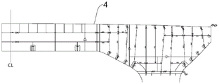
FIG. 4 is a schematic structural view of the main deck assembly of the connecting bridge section of FIG. 1;
FIG. 5 is a schematic structural view of a longitudinal wall assembly connecting the bridge segments of FIG. 1;
FIG. 6 is a schematic structural view of a transverse wall assembly connecting the bridge segments of FIG. 1;
FIG. 7 is a front view of a transverse wall assembly of the connecting bridge segment of FIG. 6;
FIG. 8 is a schematic structural view of the flat outer plate assembly of the connecting bridge segment of FIG. 1;
FIG. 9 is a schematic structural view of a planar rib assembly connecting the bridge segments of FIG. 1;
FIG. 10 is a schematic structural view of the curved rib assembly of the connecting bridge segment of FIG. 1;
FIG. 11 is a schematic view of the construction of a false rib plate of the connecting bridge segment of FIG. 1;
FIG. 12 is a schematic view of the assembly of the inboard rib assembly of the curved rib assembly of FIG. 10 with the reinforcing form;
FIG. 13 is a schematic structural view of the conformal template of FIG. 1 connecting the bridge segments;
FIG. 14 is a pictorial illustration of a position line connecting the bridge segments of FIG. 1;
fig. 15 is an assembled structural schematic of the connecting bridge segment of fig. 1.
In the figure, 1, a main deck assembly; 11. a main deck; 12. a longitudinal deck bone; 13. strengthening the longitudinal bone; 14. a shape-preserving template; 2. a longitudinal wall assembly; 21. a mid-longitudinal wall assembly; 22. a side longwall assembly; 23. a longitudinal wall panel; 24. a wallboard stringer; 3. reinforcing ribs; 4. a transverse wall assembly; 41. a transverse wall plate; 42. a wallboard transverse rib; 5. an outer plate assembly; 51. a flat outer plate assembly; 511. a flat outer plate; 52. a curved outer plate assembly; 521. a curved outer plate; 53. an outer plate rib; 6. a planar rib plate assembly; 61. a middle rib plate; 7. a curved surface rib plate assembly; 71. an inboard rib plate assembly; 711. an inboard rib plate; 72. an outboard rib plate assembly; 721. an outboard rib plate; 73. a panel; 74. reinforcing the template; 8. positioning a line; 81. a centerline; 82. a horizontal line; 83. a longitudinal seam line; 84. a structural line; 85. a rib line; 9. a false rib plate.
Detailed Description
The following detailed description of embodiments of the present invention is provided in connection with the accompanying drawings and examples. The following examples are intended to illustrate the invention but are not intended to limit the scope of the invention.
A preferred embodiment of the method for manufacturing a connecting bridge segment according to the present invention is, as shown in fig. 1 to 15, a method for manufacturing a connecting bridge segment used for manufacturing a connecting bridge segment in a catamaran, in which the connecting bridge is generally symmetrical about the center of the catamaran, so that the segment is manufactured by dividing the connecting bridge into two segments with the center of the connecting bridge as a joint.
The manufacturing method of the connecting bridge segment comprises the following steps:
the method comprises the steps of firstly, segmenting a connecting bridge into a main deck component 1, a longitudinal wall component 2, a transverse wall component 4, an outer plate component 5, a plane rib plate component 6 and a curved surface rib plate component 7, and respectively assembling the main deck component 1, the longitudinal wall component 2, the transverse wall component 4, the outer plate component 5 and the plane rib plate component 6 into a whole. During assembly, assembly is carried out according to technological requirements, and welding shrinkage is increased and decreased during welding so as to ensure that welding allowance exists during later welding.
The main deck component 1 comprises a main deck 11, a deck longitudinal frame 12 and a reinforcing longitudinal frame 13, wherein the reinforcing longitudinal frame 13 is connected to the deck longitudinal frame 12, and the deck longitudinal frame 12 and the reinforcing longitudinal frame 13 are fixedly welded on the main deck 11 according to the drawing. The area of the main deck assembly 1 is usually large, and the main deck assembly 1 can be divided into a plurality of assemblies according to the hoisting capacity so as to reduce the deformation of the main deck assembly 1.
The longitudinal wall components 2 are divided into two groups, the two groups of longitudinal wall components 2 are respectively a middle longitudinal wall component 21 and a side longitudinal wall component 22, the middle longitudinal wall component 21 is positioned at the middle line position of the connecting bridge, the side longitudinal wall component 22 is positioned at the end part of the connecting bridge, and the structures of the middle longitudinal wall component 21 and the side longitudinal wall component 22 are the same. The vertical wall assembly 2 comprises vertical wall plates 23, wall plate vertical ribs 24 and reinforcing ribs 3, wherein the reinforcing ribs 3 are connected between two adjacent wall plate vertical ribs 24, and the wall plate vertical ribs 24 and the reinforcing ribs 3 are respectively welded and fixed on the vertical wall plates 23.
There are several groups of transverse wall elements 4, the transverse wall elements 4 forming dividing panels connecting the different compartments on the bridge. The transverse wall assembly 4 comprises a transverse wall plate 41, transverse wall plates 42 and reinforcing ribs 3, wherein the reinforcing ribs 3 are connected between the two adjacent transverse wall plates 42, and the transverse wall plates 42 and the reinforcing ribs 3 are respectively welded and fixed on the transverse wall plate 41.
The outer panel assembly 5 is intended to be arranged on the outer side of the inboard side, forming the outer wall surface of the connecting bridge segment. The outer panel assembly 5 includes a straight outer panel assembly 51 and a curved outer panel assembly 52 with a smooth transition between the straight outer panel assembly 51 and the curved outer panel assembly 52. The outer plate component 5 is divided into a straight outer plate component 51 and a curved surface outer plate component 52, the structure of the curved surface outer plate component 52 is complex, the occupied space is large when the curved surface outer plate component is assembled, the two components can be assembled respectively, the efficiency is improved, and the later installation is convenient.
The flat outer panel assembly 51 includes a flat outer panel 511, outer panel ribs 53, and reinforcing bars 3, and the outer panel ribs 53 and the reinforcing bars 3 are welded and fixed to the flat outer panel 511. The curved outer plate assembly 52 comprises a curved outer plate 521, an outer plate rib 53 and a reinforcing rib 3, wherein the outer plate rib 53 and the reinforcing rib 3 are welded and fixed on the curved outer plate 521.
The planar rib plate assembly 6 comprises a middle rib plate 61 and a reinforcing rib 3, the reinforcing rib 3 is welded and fixed on the middle rib plate 61, and the middle rib plate 61 is arranged between the main deck assembly 1 and the straight outer plate assembly 51 and plays a role in supporting and reinforcing the structural strength of the main deck 11 and the straight outer plate 511.
The curved surface rib plate assembly 7 comprises an inboard rib plate assembly 71 and an outboard rib plate assembly 72, the inboard rib plate assembly 71 and the outboard rib plate assembly 72 are assembled to form a complete framework, the curved surface rib plate assembly 7 is divided into the inboard rib plate assembly 71 and the outboard rib plate assembly 72, the volume of each assembly can be reduced, and assembly is facilitated. The inboard rib assembly 71 includes an inboard rib 711, a rib 3, and a panel 73, the panel 73 being welded perpendicularly to an end of the inboard rib 711, and the rib 3 being welded perpendicularly to a side of the inboard rib 711. Outboard rib assembly 72 includes outboard rib 721, rib 3, and panel 73, with panel 73 being welded perpendicularly to the end of outboard rib 721 and rib 3 being welded perpendicularly to the side of outboard rib 721.
And step two, assembling the curved surface rib plate assemblies 7 in the step one into a frame structure.
Preferably, the inboard rib plate assembly 71 is assembled into a C-shaped rib frame, temporary reinforcement is performed at an opening of the rib frame formed by the inboard rib plate assembly 71, the temporary reinforcement is a welding reinforcement template 74, two ends of the reinforcement template 74 are respectively welded with two ends of the rib frame, the inboard rib plate assembly 71 is large in size and large in span, and the reinforcement template 74 can prevent the inboard rib plate assembly 71 from deforming, so that the later-stage construction accuracy is ensured.
Preferably, when the inner side rib plate assembly 71 is assembled, the position of the positioning line 8 of the frame structure is ejected on the steel plate, the positioning line 8 comprises a central line 81, a horizontal line 82, a longitudinal seam line 83, a structure line 84 and a rib line 85, and the positioning line 8 is inspected after ejection to ensure the accuracy of the positioning line 8. And all the rib plates of the inner side rib plate assembly 71 are assembled by taking the rib line 85 as a reference so as to ensure the assembling precision. A center line 81, a horizontal line 82, a longitudinal seam line 83 and a structural line 84 are marked on the assembled C-shaped rib UAN elevated frame by taking the positioning line 8 on the steel plate as a reference, so that the inner side rib plate assembly 71 can be installed at the later stage conveniently.
Preferably, the outboard rib plate assembly 72 is assembled into a sheet rib cage. When the rib frame is manufactured, jig frame templates are respectively arranged at the positive rib position and the head and tail ends of the outer board rib plate 721, and the jig frame templates at the head and tail ends are arranged at the positions where the head and tail end seams retract by 40-60 mm, preferably 50mm, so that the segmentation precision can be ensured.
At rib position positions corresponding to the transverse wall plates 41 on the outer board rib plate assembly 72, the false rib plates 9 are manufactured according to line types of the transverse wall plates 41, the width of each false rib plate 9 is 200mm, the false rib plates 9 are connected with the outer board rib plate assembly 72 through spot welding, so that the false rib plates 9 can be detached in the later period, and the smoothness of the line types can be guaranteed.
And step three, taking the main deck 11 of the main deck component 1 as a base surface for inverted installation, arranging a jig frame template on a positive rib position of the main deck 11, assembling and arranging the longitudinal wall component 2, the transverse wall component 4, the plane rib plate component 6 and the curved surface rib plate component 7 in the step two on the main deck component 1, and manufacturing sections.
Preferably, when the distance between the subsection seam and the ribbed plate or the wallboard is more than 150mm, a conformal template 14 is arranged at the head end and the tail end of the main deck 11 of the main deck assembly 1, and the conformal template 14 is arranged at the position where the end seam of the main deck 11 is retracted by 40-60 mm, preferably 50 mm.
Preferably, a plurality of shape-preserving templates 14 are arranged, the shape-preserving templates 14 are welded on the segments according to a spray line and are spliced into an integral framework, the integral framework passes through the central line 81 and the horizontal line 82 of the segments, so that the stress of the segments is uniform, the accuracy of the segments is ensured, and the shape-preserving templates 14 can be removed after the segments are installed and the integral shape is stable.
Preferably, when the segments are manufactured, attention is paid to welding each component on the main deck component 1 according to process requirements, wherein the process requirements comprise welding shrinkage, reverse deformation and the like. After the main deck 11 is positioned, the longitudinal rib lines, the rib lines 85 and the rib line are scribed on the main deck 11 based on the scribing data, the longitudinal wall members 2 and the planar rib plate members 6 are installed on the main deck 11 according to the longitudinal rib lines and the rib lines 85, and then the flat outer plate members 51 are covered on the longitudinal wall members 2 and the deck members. The inboard rib plate assembly 71 is mounted on the main deck 11 according to the rib position line, the dummy rib plate 9 corresponding to the assembly position of the lateral wall plate 41 on the outboard rib plate assembly 72 is removed, and then the outboard rib plate assembly 72 is mounted on the main deck 11 according to the rib position line. Finally, the curved outer plate assembly 52 is covered on the inner side outer plate, and the reinforcing template 74 on the inner side rib plate assembly 71 is removed.
Preferably, when the inner rib plate assembly 71 and the outer rib plate assembly 72 are installed, after the inner rib plate assembly 71 and the outer rib plate assembly 72 are assembled into a whole, positioning measurement is performed on the assembled corners, as shown in fig. 15, positioning measurement is performed on four corners a, B, C, and D in fig. 15, so that the accuracy after assembly is ensured.
To sum up, the embodiment of the present invention provides a method for manufacturing a connecting bridge segment, in which a main deck component is used as a base surface for flip-chip mounting, the connecting bridge is divided into a plurality of components, and the components are assembled into a whole, that is, the components are assembled in a modular manner, so that the manufacturing efficiency of the segment is improved.
The above description is only a preferred embodiment of the present invention, and it should be noted that, for those skilled in the art, various modifications and substitutions can be made without departing from the technical principle of the present invention, and these modifications and substitutions should also be regarded as the protection scope of the present invention.
Claims (8)
1. A method for manufacturing a connecting bridge section is characterized by comprising the following steps of firstly, dividing the connecting bridge section into a main deck component, a longitudinal wall component, a transverse wall component, an outer plate component, a plane rib plate component and a curved surface rib plate component, and respectively assembling the main deck component, the longitudinal wall component, the transverse wall component, the outer plate component and the plane rib plate component into a whole; step two, splicing the curved surface rib plate components in the step one into a frame structure; step three, taking the main deck of the main deck assembly as a base surface for inverted installation, arranging a jig frame template on a front rib position of the main deck, assembling and arranging the longitudinal wall assembly, the transverse wall assembly, the plane rib plate assembly and the curved surface rib plate assembly in the step two on the main deck assembly, and manufacturing sections; in the step two, the inboard rib plate component is spliced into a C-shaped rib frame, and the outboard rib plate component is spliced into a sheet rib frame; and step two, temporarily reinforcing the rib frame assembled by the inner side rib plate assemblies.
2. A method for manufacturing a connecting bridge section according to claim 1, wherein in the second step, when the outer side rib plate assemblies are assembled into the frame structure, the jig frame templates are respectively arranged at the positive rib position and the head end and the tail end of the outer side rib plate.
3. A method for manufacturing a connecting bridge section according to claim 2, wherein in the second step, the jig frame templates at the head end and the tail end of the outboard rib plate are arranged at the positions where the head end seam and the tail end seam are retracted by 40-60 mm.
4. A method for manufacturing a connecting bridge segment according to any one of claims 1 to 3, wherein in the second step, the position of the positioning line of the framework structure is ejected from the steel plate, the positioning line includes a center line, a horizontal line, a longitudinal line, a structural line and a rib line, each rib plate is assembled with the rib line as a reference, and the center line, the horizontal line, the longitudinal line and the structural line are drawn on the assembled framework structure with the positioning line of the steel plate as a reference.
5. A method for making a connecting bridge section according to any one of claims 1 to 3, wherein in step three, when the distance between the section seam and the ribbed slab or the wallboard is more than 150mm, a conformal template is arranged at the head end and the tail end of the main deck assembly.
6. A method for manufacturing a connecting bridge section according to claim 5, wherein in step three, a conformal template is arranged at the position where the end seam of the main deck is retracted by 40-60 mm.
7. A method of constructing a connecting bridge section according to claim 5 wherein the form-retaining forms are provided in plurality and are assembled to form a unitary frame which passes through the centerline and horizontal line of the section.
8. A method for manufacturing a connecting bridge section according to any one of claims 1 to 3, wherein in step three, the longitudinal rib lines, the rib lines and the rib position lines are marked on the main deck, the longitudinal wall components and the horizontal rib plate components are installed on the main deck according to the longitudinal rib lines and the rib lines, the curved rib plate components are installed on the main deck according to the rib position lines, the outer plate components are installed in a covering mode, and finally the horizontal wall components are installed on the main deck according to the rib numbers.
Priority Applications (1)
| Application Number | Priority Date | Filing Date | Title |
|---|---|---|---|
| CN202010925783.XA CN112124526B (en) | 2020-09-04 | 2020-09-04 | Method for manufacturing connecting bridge segment |
Applications Claiming Priority (1)
| Application Number | Priority Date | Filing Date | Title |
|---|---|---|---|
| CN202010925783.XA CN112124526B (en) | 2020-09-04 | 2020-09-04 | Method for manufacturing connecting bridge segment |
Publications (2)
| Publication Number | Publication Date |
|---|---|
| CN112124526A CN112124526A (en) | 2020-12-25 |
| CN112124526B true CN112124526B (en) | 2022-07-05 |
Family
ID=73848062
Family Applications (1)
| Application Number | Title | Priority Date | Filing Date |
|---|---|---|---|
| CN202010925783.XA Active CN112124526B (en) | 2020-09-04 | 2020-09-04 | Method for manufacturing connecting bridge segment |
Country Status (1)
| Country | Link |
|---|---|
| CN (1) | CN112124526B (en) |
Families Citing this family (1)
| Publication number | Priority date | Publication date | Assignee | Title |
|---|---|---|---|---|
| CN113172563B (en) * | 2021-04-23 | 2023-03-07 | 中船黄埔文冲船舶有限公司 | Plane subsection assembling jig frame and using method thereof |
Citations (8)
| Publication number | Priority date | Publication date | Assignee | Title |
|---|---|---|---|---|
| JPH06156364A (en) * | 1992-11-16 | 1994-06-03 | Shinkurushima Dock:Kk | Hull body block assembling method for steel vessel |
| CN103523168A (en) * | 2013-10-10 | 2014-01-22 | 福建省马尾造船股份有限公司 | Cross structure area segmentation manufacturing process of CSS platform and special-purpose inclined cutting jig frame |
| CN105539724A (en) * | 2015-12-23 | 2016-05-04 | 江苏现代造船技术有限公司 | Hull curved block manufacturing method |
| CN107235118A (en) * | 2017-06-08 | 2017-10-10 | 中船黄埔文冲船舶有限公司 | A kind of supplementary structure built for boat segmental and preparation method thereof |
| CN108146578A (en) * | 2017-12-21 | 2018-06-12 | 沪东中华造船(集团)有限公司 | A kind of manufacturing method of two phase stainless steel chemical tanker topside segmentation |
| CN108177730A (en) * | 2017-12-25 | 2018-06-19 | 沪东中华造船(集团)有限公司 | A kind of integrated method of construction of topside segmentation |
| CN108860456A (en) * | 2018-06-20 | 2018-11-23 | 中航鼎衡造船有限公司 | A kind of cabin method of construction |
| CN110254623A (en) * | 2019-06-28 | 2019-09-20 | 中船黄埔文冲船舶有限公司 | A kind of production method of submerged body segmentation |
-
2020
- 2020-09-04 CN CN202010925783.XA patent/CN112124526B/en active Active
Patent Citations (8)
| Publication number | Priority date | Publication date | Assignee | Title |
|---|---|---|---|---|
| JPH06156364A (en) * | 1992-11-16 | 1994-06-03 | Shinkurushima Dock:Kk | Hull body block assembling method for steel vessel |
| CN103523168A (en) * | 2013-10-10 | 2014-01-22 | 福建省马尾造船股份有限公司 | Cross structure area segmentation manufacturing process of CSS platform and special-purpose inclined cutting jig frame |
| CN105539724A (en) * | 2015-12-23 | 2016-05-04 | 江苏现代造船技术有限公司 | Hull curved block manufacturing method |
| CN107235118A (en) * | 2017-06-08 | 2017-10-10 | 中船黄埔文冲船舶有限公司 | A kind of supplementary structure built for boat segmental and preparation method thereof |
| CN108146578A (en) * | 2017-12-21 | 2018-06-12 | 沪东中华造船(集团)有限公司 | A kind of manufacturing method of two phase stainless steel chemical tanker topside segmentation |
| CN108177730A (en) * | 2017-12-25 | 2018-06-19 | 沪东中华造船(集团)有限公司 | A kind of integrated method of construction of topside segmentation |
| CN108860456A (en) * | 2018-06-20 | 2018-11-23 | 中航鼎衡造船有限公司 | A kind of cabin method of construction |
| CN110254623A (en) * | 2019-06-28 | 2019-09-20 | 中船黄埔文冲船舶有限公司 | A kind of production method of submerged body segmentation |
Also Published As
| Publication number | Publication date |
|---|---|
| CN112124526A (en) | 2020-12-25 |
Similar Documents
| Publication | Publication Date | Title |
|---|---|---|
| CN109334858B (en) | Method for building superstructure of ship | |
| CN101544268B (en) | Method for half-breadth double-span total assembling and building in shipbuilding | |
| CN110329425B (en) | Precision control method for U-shaped block of duplex stainless steel chemical tanker | |
| CN110877693B (en) | Intelligent manufacturing method for double-layer bottom section of LNG ship | |
| CN110550146A (en) | Construction method of ship garage or superstructure | |
| CN110667801A (en) | Sectional manufacturing method for deck of dome of LNG ship | |
| CN112124526B (en) | Method for manufacturing connecting bridge segment | |
| CN112027020B (en) | Three-step ladder type sectional construction method | |
| CN111532372B (en) | Integrated inspection channel for ballast tank of ore carrier and construction method thereof | |
| CN110254623B (en) | Manufacturing method of submerged body segment | |
| CN110937080B (en) | Construction method for assembling transverse compartment top plate of container ship | |
| CN115285308A (en) | Novel container ship LNG cabin segmentation division method | |
| CN112078751B (en) | Construction method for lower pier seat section of FLNG ship | |
| CN113815807B (en) | Container bilge part circle-turning segmented structure and segmented construction method thereof | |
| CN115258088A (en) | Segmented merging construction method for hatch circumference and side box of container ship | |
| CN115321444A (en) | Work platform and aerial work vehicle | |
| CN212332873U (en) | Integrated inspection channel for ballast tank of ore carrier | |
| CN112977715A (en) | Articulated end connection's slot-shaped bulkhead | |
| CN212611887U (en) | Large-span arched multi-cavity variable-cross-section variable-plate thick box beam | |
| CN111703552A (en) | Manufacturing method of LNG filling ship cab segment | |
| CN215699251U (en) | Welding type skin milling fixture | |
| CN115070242B (en) | Manufacturing method of steel box girder with embedded chord | |
| CN219821710U (en) | Integral sectional assembly structure of movable ship section | |
| CN216468302U (en) | High-strength large-span deck structure convenient to maintain | |
| CN213502004U (en) | Side plate and bottom plate connecting structure of light-weight carriage |
Legal Events
| Date | Code | Title | Description |
|---|---|---|---|
| PB01 | Publication | ||
| PB01 | Publication | ||
| SE01 | Entry into force of request for substantive examination | ||
| SE01 | Entry into force of request for substantive examination | ||
| GR01 | Patent grant | ||
| GR01 | Patent grant | ||
| EE01 | Entry into force of recordation of patent licensing contract |
Application publication date: 20201225 Assignee: GUANGZHOU WENCHUAN HEAVY INDUSTRY Co.,Ltd. Assignor: CSSC HUANGPU WENCHONG SHIPBUILDING Co.,Ltd. Contract record no.: X2023980037443 Denomination of invention: A Manufacturing Method for Connecting Bridge Segments Granted publication date: 20220705 License type: Common License Record date: 20230704 |
|
| EE01 | Entry into force of recordation of patent licensing contract |