CN112123462A - Multi-angle cutting equipment for wood production - Google Patents
Multi-angle cutting equipment for wood production Download PDFInfo
- Publication number
- CN112123462A CN112123462A CN202011062087.7A CN202011062087A CN112123462A CN 112123462 A CN112123462 A CN 112123462A CN 202011062087 A CN202011062087 A CN 202011062087A CN 112123462 A CN112123462 A CN 112123462A
- Authority
- CN
- China
- Prior art keywords
- fixedly connected
- wood
- cutting
- rod
- base
- Prior art date
- Legal status (The legal status is an assumption and is not a legal conclusion. Google has not performed a legal analysis and makes no representation as to the accuracy of the status listed.)
- Pending
Links
Images


Classifications
-
- B—PERFORMING OPERATIONS; TRANSPORTING
- B27—WORKING OR PRESERVING WOOD OR SIMILAR MATERIAL; NAILING OR STAPLING MACHINES IN GENERAL
- B27C—PLANING, DRILLING, MILLING, TURNING OR UNIVERSAL MACHINES FOR WOOD OR SIMILAR MATERIAL
- B27C5/00—Machines designed for producing special profiles or shaped work, e.g. by rotary cutters; Equipment therefor
Landscapes
- Life Sciences & Earth Sciences (AREA)
- Engineering & Computer Science (AREA)
- Mechanical Engineering (AREA)
- Wood Science & Technology (AREA)
- Forests & Forestry (AREA)
- Dovetailed Work, And Nailing Machines And Stapling Machines For Wood (AREA)
Abstract
The invention discloses multi-angle cutting equipment for wood production, which comprises a base, wherein a control panel is fixedly installed at the upper end of the base, a power line is connected onto the control panel, a fixed plate is fixedly connected onto the upper surface of the right side of the base, a supporting concave seat is fixedly connected onto the left side of the upper surface of the base, a screw rod driving device is arranged between the supporting concave seat and the fixed plate, and the screw rod driving device comprises a guide rod and a first threaded rod; the screw rod driving device is provided with a wood fixing device, and the wood fixing device comprises an upper fixing seat and a lower fixing seat of a supporting plate. According to the multi-angle cutting equipment for wood production, disclosed by the invention, wood can be fixed through the wood fixing device, so that the wood can be kept stable in the cutting process, the cutting precision is improved, the cutting motor is convenient to adjust the angle through the rotating block, the practicability is strong, the wood fixing device can move on the base, the wood does not need to be manually pushed to move, and the cutting is more convenient.
Description
Technical Field
The invention relates to the field of wood cutting, in particular to multi-angle cutting equipment for wood production.
Background
The wood processing technology comprises basic processing technologies such as wood cutting, wood drying, wood gluing and wood surface decoration, and functional processing technologies such as wood protection and wood modification. Cutting includes sawing, planing, milling, drilling, sanding, and the like. The method of cutting differs from other materials due to the effects of wood texture, grain, etc. The moisture content of wood also affects the cutting process, for example, the veneer making method and wood chip production require wet material cutting, and most of the workpieces require dry material cutting. Drying is generally referred to exclusively as drying of the finished material. Drying of other wood materials, such as veneers, shavings, wood fibers, etc., are part of the manufacturing process of plywood, particle board, fiberboard, respectively. The emergence and development of wood adhesives and gluing techniques are not only the main factor for improving the technical level of wood processing, but also the prerequisite for the production of reconstituted wood and improved wood, such as various laminated bricks, glued wood and other products.
Wood cutting equipment is a processing equipment who uses commonly in wood working, current wood working equipment has more defect, for example, the inconvenient angle regulation of current wood cutting equipment, in addition, current wood cutting equipment generally all needs artifical removal timber or the material loading to accomplish ligneous cutting operation, in addition, modern wood cutting equipment is carrying out the in-process of cutting to timber, timber takes place to rock easily, lead to the problem of cutting precision decline, for this reason, we provide a multi-angle cutting equipment for wood production.
Disclosure of Invention
The invention aims to provide multi-angle cutting equipment for wood production, which can solve the problem that the conventional wood cutting equipment in the background technology is inconvenient to adjust the angle and simultaneously solve the problem that the conventional wood cutting equipment needs to manually push wood to move for cutting, so that the operation is troublesome.
In order to achieve the purpose, the invention provides the following technical scheme: a multi-angle cutting device for wood production comprises a base, wherein a control panel is fixedly mounted at the upper end of the base, a power line is connected onto the control panel, a fixed plate is fixedly connected onto the upper surface of the right side of the base, a supporting concave seat is fixedly connected onto the left side of the upper surface of the base, a screw rod driving device is arranged between the supporting concave seat and the fixed plate, and the screw rod driving device comprises a guide rod and a first threaded rod; the screw rod driving device is provided with a wood fixing device, the wood fixing device comprises an upper fixing seat and a supporting plate lower fixing seat, the front end of the lower fixing seat is connected with the guide rod in a sliding mode, and the rear end of the lower fixing seat is in threaded connection with the first threaded rod; and a lifting cutting device is arranged on the left side of the upper surface of the base.
Furthermore, the guide rod is fixedly connected between the supporting concave seat and the fixing plate, two ends of the first threaded rod are respectively rotatably connected with the supporting concave seat and the fixing plate, and one end of the first threaded rod rotatably connected with the fixing plate penetrates out of the fixing plate.
Further, the one end fixedly connected with driven pulleys of fixed plate is worn out to first threaded rod, is connected with driving pulley through driving belt on the driven pulleys, and driving pulley's middle part fixedly connected with drive shaft, drive shaft connection have driving motor's output shaft, and driving motor installs on the upper surface of base, is connected with the power cord on the driving motor, driving motor's input and control panel's output electric connection.
Further, go up the upper end fixedly connected with sleeve pipe of fixing base, the intraductal buffer beam that is provided with of cover, the upper end of buffer beam and the lower fixed surface of backup pad are connected, and the outside cover of buffer beam is equipped with first spring, and the both ends of first spring are connected with the lower surface of base and sheathed tube last fixed surface respectively, and the buffer beam is located the sheathed tube medial part and goes up fixedly connected with third slider.
Further, a third sliding groove is formed in the inner wall of the sleeve, a third sliding block is arranged in the third sliding groove in a sliding mode, a sliding rod is sleeved on the third sliding block in a sliding mode, the sliding rod is fixedly connected into the third sliding groove, a second spring is sleeved on the sliding rod, the second spring is fixedly connected with the bottom surface of the third sliding groove and the bottom surface of the third sliding block, and the bottom of the buffer rod is fixedly connected with the bottom of the sleeve through the third spring.
Further, go up the fixing base setting in the upper end of fixing base down, the lower surface of going up the fixing base has been seted up the arc wall, and the arc wall has been seted up down to the upper surface of lower fixing base, and the bore of going up the arc wall is less than the bore of arc wall down, and the right side of backup pad is rotated and is connected with the second threaded rod, fixedly connected with connecting plate on the bottom side of lower fixing base, and the lower extreme of second threaded rod rotates through the bearing and is connected with the bearing frame, and bearing frame fixed mounting is at the upper surface.
Further, threaded connection has first slider on the second threaded rod, the upper end fixedly connected with riser of first slider, and the lower fixed surface of the upper end of riser and backup pad is connected, has seted up first spout on the lateral wall of lower fixing base, and first slider slides and sets up in first spout, and both sides fixedly connected with second slider around the first slider has seted up the second spout on the inner wall around the first spout, and the second slider slides and sets up in the second spout.
Further, lift cutting device includes the support frame, support frame fixed mounting is at the upper surface of base, the upper end fixed mounting of support frame has the lift cylinder, be connected with the power cord on the lift cylinder, the input of lift cylinder and control panel's output electric connection, fixedly connected with mounting panel on the lower extreme output shaft of lift cylinder, the lower extreme of mounting panel is provided with the cutting motor, be connected with the power cord on the cutting motor, the input of cutting motor and control panel's output electric connection, fixedly connected with cutting knife on the output shaft of cutting motor.
Further, both ends fixedly connected with fixed block around the upper surface right side of cutting motor, fixedly connected with connecting axle between the fixed block of both sides around, it is connected with the turning block to rotate on the connecting axle, the upper end of turning block is connected with the lower fixed surface of mounting panel, both ends downside fixedly connected with arc around the mounting panel, it is provided with the arc and leads to the groove to run through on the arc, both ends outside fixedly connected with connecting rod around the cutting motor, the connecting rod sets up at the logical inslot of arc, be provided with the external screw thread on the outer wall of connecting rod, threaded connection has the nut on the external screw thread of.
Further, the use method of the multi-angle cutting equipment for wood production specifically comprises the following steps:
step 1: connecting power lines of a cutting motor, a lifting cylinder, a driving motor and a control panel with an external power supply, and placing wood between the support concave seat and the wood fixing device;
step 2: the cutting motor rotates on the connecting shaft through the rotating block, the angle of the cutting motor is changed, and after the cutting motor rotates to a proper angle, the nut is tightly attached to the outer surface of the cutting motor through rotating the nut, so that the cutting motor is fixed, and the angle is adjusted;
and step 3: the fixing base downstream in driving through rotating the second threaded rod to make the fixing base fix ligneous one end with fixing base down, control driving motor, cutting motor and lift cylinder through control panel and carry out work, make timber remove at the upper surface of base, the in-process cutting motor that removes drives the cutting knife and rotates and cut timber.
Compared with the prior art, the invention has the beneficial effects that:
1. the wood clamping device is provided with an upper fixed seat and a lower fixed seat, wood is placed between the upper fixed seat and the lower fixed seat, a second threaded rod is rotated, a first sliding block is connected to the second threaded rod in a threaded manner, the second sliding block slides in a second sliding groove, the first sliding block is limited, the first sliding block can lift in the first sliding groove, so that a supporting plate is driven by a vertical plate to lift, the upper fixed seat is driven to lift in the lifting process of the supporting plate, an upper arc-shaped groove is formed in the lower surface of the upper fixed seat, a lower arc-shaped groove is formed in the upper surface of the lower fixed seat, so that the wood between the upper fixed seat and the lower fixed seat can be clamped tightly through the upper arc-shaped groove and the lower arc-shaped groove, a driving motor is driven to work through a control panel, the driving motor drives the first threaded rod to rotate through a driving belt pulley and a driven belt pulley, and, the wood is driven to move in the sliding process, the lifting cylinder and the cutting motor are controlled to work through the control panel at the moment, the cutting motor cuts the moved wood in the descending process, manual pressing is not needed to push the wood to move, the wood is kept stable in the cutting process due to the matching of the upper fixing seat and the lower fixing seat, and the cutting precision of the wood is improved;
2. the cutting motor can rotate on the connecting shaft through the rotating block, so that the angle of the cutting motor is changed, the angle of the cutting knife is changed, the wood can be cut in multiple angles, the connecting rod can rotate in the arc-shaped through groove in the rotating process of the cutting motor, and after the angle is determined, the nut on the connecting rod is rotated to be tightly attached to the outer wall of the arc-shaped plate, so that the fixing of the cutting motor is completed, and the wood can be cut at a specific angle;
3. according to the invention, the sleeve is fixedly connected with the upper end of the upper fixing seat, the upper end of the sleeve is connected with the supporting plate through the movably arranged buffer rod, when the second threaded rod is rotated to drive the supporting plate and the upper fixing seat to move downwards, the first spring on the outer surface of the buffer rod is compressed for the first time, then the second spring on the sliding rod is compressed for the second time, and the third spring fixed between the buffer rod and the bottom of the sleeve is compressed for the third time, so that the buffer effect is achieved, the pressure of wood between the upper fixing seat and the lower fixing seat can be effectively relieved, the phenomenon that the wood surface generates indentation due to direct rigid contact is prevented, and particularly, the protection effect on the wood surface can be effectively achieved during expensive wood processing.
Drawings
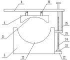
FIG. 1 is a schematic view of the overall structure of embodiment 1 of the present invention;
FIG. 2 is a top view of example 1 of the present invention;
fig. 3 is a schematic view of the overall structure of the wood fixing device in embodiment 1 of the present invention;
FIG. 4 is an enlarged view taken at A of FIG. 3 in accordance with the present invention;
fig. 5 is a schematic view of the overall structure of a cutting motor and a mounting plate in embodiment 2 of the present invention;
FIG. 6 is a side view of a cutting motor and a mounting plate in embodiment 2 of the invention;
fig. 7 is a front view of a wood cutting device in embodiment 3 of the invention;
fig. 8 is a sectional view of the sleeve and the buffer rod in embodiment 3 of the present invention.
In the figure: 1. a lifting cylinder; 2. a support frame; 3. a support recess; 4. a support plate; 5. a lower fixed seat; 6. an upper fixed seat; 7. a fixing plate; 8. a guide bar; 9. a driven pulley; 10. a drive belt; 11. a driving pulley; 12. a drive shaft; 13. a drive motor; 14. a base; 15. a first threaded rod; 16. a control panel; 17. a cutting knife; 18. cutting the motor; 19. mounting a plate; 20. a lower arc-shaped groove; 21. an upper arc-shaped groove; 22. a connecting plate; 23. a bearing seat; 24. a second threaded rod; 25. a vertical plate; 26. a second chute; 27. a first chute; 28. a second slider; 29. a first slider; 30. a fixed block; 31. a connecting shaft; 32. an arc-shaped plate; 33. an arc-shaped through groove; 34. a connecting rod; 35. a nut; 36. rotating the block; 37. a third spring; 38. a sleeve; 39. a buffer rod; 40. a first spring; 41. a third chute; 42. a second spring; 43. a slide bar; 44. and a third slide block.
Detailed Description
The technical solutions in the embodiments of the present invention will be clearly and completely described below with reference to the drawings in the embodiments of the present invention, and it is obvious that the described embodiments are only a part of the embodiments of the present invention, and not all of the embodiments. All other embodiments, which can be derived by a person skilled in the art from the embodiments given herein without making any creative effort, shall fall within the protection scope of the present invention.
Example 1
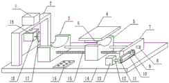
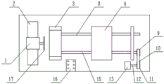
Referring to fig. 1-4, a multi-angle cutting apparatus for wood production comprises a base 14, a control panel 16 is fixedly installed at the upper end of the base 14, a power cord is connected to the control panel 16, a fixing plate 7 is fixedly connected to the upper surface of the right side of the base 14, a supporting recess 3 is fixedly connected to the left side of the upper surface of the base 14, a screw rod driving device is arranged between the supporting recess 3 and the fixing plate 7, the screw rod driving device comprises a guide rod 8 and a first threaded rod 15, the guide rod 8 is fixedly connected between the supporting recess 3 and the fixing plate 7, two ends of the first threaded rod 15 are respectively rotatably connected with the supporting recess 3 and the fixing plate 7, one end of the first threaded rod 15 rotatably connected with the fixing plate 7 penetrates out of the fixing plate 7, one end of the first threaded rod 15 penetrating out of the fixing plate 7 is fixedly connected with a driven, the middle part of the driving belt wheel 11 is fixedly connected with a driving shaft 12, the driving shaft 12 is connected with an output shaft of a driving motor 13, the driving motor 13 is arranged on the upper surface of a base 14, the driving motor 13 is connected with a power line, and the input end of the driving motor 13 is electrically connected with the output end of a control panel 16;
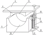
the screw rod driving device is provided with a wood fixing device, the wood fixing device comprises an upper fixing seat 6 and a lower fixing seat 5, the front end of the lower fixing seat 5 is connected with a guide rod 8 in a sliding manner, the rear end of the lower fixing seat 5 is connected with a first threaded rod 15 in a threaded manner, the upper fixing seat 6 is arranged at the upper end of the lower fixing seat 5, the lower surface of the upper fixing seat 6 is provided with an upper arc-shaped groove 21, the upper surface of the lower fixing seat 5 is provided with a lower arc-shaped groove 20, the caliber of the upper arc-shaped groove 21 is smaller than that of the lower arc-shaped groove 20, the upper surface of the upper fixing seat 6 is fixedly connected with a supporting plate 4, the right side of the supporting plate 4 is rotatably connected with a second threaded rod 24, the bottom side edge of the lower fixing seat 5 is fixedly connected with a connecting plate 22, the lower end of the second, the upper end of the first sliding block 29 is fixedly connected with a vertical plate 25, the upper end of the vertical plate 25 is fixedly connected with the lower surface of the supporting plate 4, the side wall of the lower fixing seat 5 is provided with a first sliding groove 27, the first sliding block 29 is arranged in the first sliding groove 27 in a sliding manner, the front side and the rear side of the first sliding block 29 are fixedly connected with second sliding blocks 28, the front inner wall and the rear inner wall of the first sliding groove 27 are provided with second sliding grooves 26, the second sliding blocks 28 are arranged in the second sliding grooves 26 in a sliding manner, and the first sliding block 29 slides more stably in the first sliding groove 27 through the matching of the second sliding blocks 28 and the second sliding grooves 26;
Before the wood clamping device is used, power lines of the cutting motor 18, the lifting cylinder 1, the driving motor 13 and the control panel 16 are connected with an external power supply, wood is placed between the supporting recess 3 and the wood fixing device, the wood is placed between the upper fixing seat 6 and the lower fixing seat 5, the second threaded rod 24 is rotated, the first sliding block 29 is in threaded connection with the second threaded rod 24, the second sliding block 28 slides in the second sliding groove 26, the first sliding block 29 is limited, the first sliding block 29 can lift in the first sliding groove 27, so that the supporting plate 4 is driven to lift through the vertical plate 25, the upper fixing seat 6 is driven to lift in the lifting process of the supporting plate 4, the upper arc-shaped groove 21 is formed in the lower surface of the upper fixing seat 6, the lower arc-shaped groove 20 is formed in the upper surface of the lower fixing seat 5, so that the wood between the upper fixing seat 6 and the lower fixing seat 5 can be clamped through the upper arc-shaped groove 21, drive driving motor 13 work through control panel 16, driving motor 13 drives first threaded rod 15 through driving pulley 11 and driven pulley 9 and rotates, because the limiting displacement of guide bar 8, make lower fixing base 5 on the first threaded rod 15 horizontal slip on base 14, gliding in-process drives timber and removes, work through control panel 16 control lift cylinder 1 and cutting motor 18 this moment, cutting motor 18 cuts the timber of removing the in-process that descends, it removes to need not the manual work and press the promotion timber, go up fixing base 6 and lower fixing base 5's cooperation and make timber remain stable in cutting process, improve ligneous cutting accuracy.
Example 2
Referring to fig. 5-6, a multi-angle cutting device for wood production comprises a base 14, a control panel 16 is fixedly installed at the upper end of the base 14, a power cord is connected on the control panel 16, a fixing plate 7 is fixedly connected to the upper surface of the right side of the base 14, a supporting recess 3 is fixedly connected to the left side of the upper surface of the base 14, a screw rod driving device is arranged between the supporting recess 3 and the fixing plate 7, the screw rod driving device comprises a guide rod 8 and a first threaded rod 15, the guide rod 8 is fixedly connected between the supporting recess 3 and the fixing plate 7, two ends of the first threaded rod 15 are respectively rotatably connected with the supporting recess 3 and the fixing plate 7, one end of the first threaded rod 15 rotatably connected with the fixing plate 7 penetrates out of the fixing plate 7, one end of the first threaded rod 15 penetrating out of the fixing plate 7 is fixedly connected with a driven, the middle part of the driving belt wheel 11 is fixedly connected with a driving shaft 12, the driving shaft 12 is connected with an output shaft of a driving motor 13, the driving motor 13 is arranged on the upper surface of a base 14, the driving motor 13 is connected with a power line, and the input end of the driving motor 13 is electrically connected with the output end of a control panel 16;
the screw rod driving device is provided with a wood fixing device, the wood fixing device comprises an upper fixing seat 6 and a lower fixing seat 5, the front end of the lower fixing seat 5 is connected with a guide rod 8 in a sliding manner, the rear end of the lower fixing seat 5 is connected with a first threaded rod 15 in a threaded manner, the upper fixing seat 6 is arranged at the upper end of the lower fixing seat 5, the lower surface of the upper fixing seat 6 is provided with an upper arc-shaped groove 21, the upper surface of the lower fixing seat 5 is provided with a lower arc-shaped groove 20, the caliber of the upper arc-shaped groove 21 is smaller than that of the lower arc-shaped groove 20, the upper surface of the upper fixing seat 6 is fixedly connected with a supporting plate 4, the right side of the supporting plate 4 is rotatably connected with a second threaded rod 24, the bottom side edge of the lower fixing seat 5 is fixedly connected with a connecting plate 22, the lower end of the second, the upper end of the first sliding block 29 is fixedly connected with a vertical plate 25, the upper end of the vertical plate 25 is fixedly connected with the lower surface of the supporting plate 4, the side wall of the lower fixed seat 5 is provided with a first sliding groove 27, the first sliding block 29 is arranged in the first sliding groove 27 in a sliding manner, the front side and the rear side of the first sliding block 29 are fixedly connected with second sliding blocks 28, the front inner wall and the rear inner wall of the first sliding groove 27 are provided with second sliding grooves 26, and the second sliding blocks 28 are arranged in the second sliding grooves 26 in a sliding manner;
a lifting cutting device is arranged on the left side of the upper surface of the base 14 and comprises a support frame 2, the support frame 2 is fixedly arranged on the upper surface of the base 14, a lifting cylinder 1 is fixedly arranged at the upper end of the support frame 2, a power cord is connected onto the lifting cylinder 1, the input end of the lifting cylinder 1 is electrically connected with the output end of the control panel 16, a mounting plate 19 is fixedly connected onto the output shaft of the lower end of the lifting cylinder 1, a cutting motor 18 is arranged at the lower end of the mounting plate 19, the power cord is connected onto the cutting motor 18, the input end of the cutting motor 18 is electrically connected with the output end of the control panel 16, and a cutting knife 17;
further, both ends fixedly connected with fixed block 30 around the upper surface right side of cutting motor 18, fixedly connected with connecting axle 31 between the fixed block 30 of both sides around, it is connected with turning block 36 to rotate on the connecting axle 31, the upper end of turning block 36 is connected with mounting panel 19's lower fixed surface, both ends downside fixedly connected with arc 32 around mounting panel 19, it is provided with arc through groove 33 to run through on the arc 32, both ends outside fixedly connected with connecting rod 34 around cutting motor 18, connecting rod 34 sets up in arc through groove 33, be provided with the external screw thread on the outer wall of connecting rod 34, threaded connection has nut 35 on the external screw thread of connecting rod 34.
This embodiment is for embodiment 2, cutting motor 18 can rotate on connecting axle 31 through turning block 36, thereby change cutting motor 18's angle, and then change cutting knife 17's angle, can carry out the cutting of multi-angle to timber, when cutting motor 18 pivoted in-process, connecting rod 34 can be at the logical 33 internal rotations of arc groove, after the angle is confirmed, through rotating nut 35 on the connecting rod 34, make nut 35 closely laminate with the outer wall of arc 32, thereby accomplish cutting motor 18's fixed, can be under specific angle to the timber cutting.
Example 3
Referring to fig. 7-8, a multi-angle cutting apparatus for wood production comprises a base 14, a control panel 16 is fixedly mounted at the upper end of the base 14, a power cord is connected to the control panel 16, a fixing plate 7 is fixedly connected to the upper surface of the right side of the base 14, a supporting recess 3 is fixedly connected to the left side of the upper surface of the base 14, a screw rod driving device is arranged between the supporting recess 3 and the fixing plate 7, the screw rod driving device comprises a guide rod 8 and a first threaded rod 15, the guide rod 8 is fixedly connected between the supporting recess 3 and the fixing plate 7, two ends of the first threaded rod 15 are respectively rotatably connected with the supporting recess 3 and the fixing plate 7, one end of the first threaded rod 15 rotatably connected with the fixing plate 7 penetrates out of the fixing plate 7, one end of the first threaded rod 15 penetrating out of the fixing plate 7 is fixedly connected with a driven, the middle part of the driving belt wheel 11 is fixedly connected with a driving shaft 12, the driving shaft 12 is connected with an output shaft of a driving motor 13, the driving motor 13 is arranged on the upper surface of a base 14, the driving motor 13 is connected with a power line, and the input end of the driving motor 13 is electrically connected with the output end of a control panel 16;
the screw rod driving device is provided with a wood fixing device, the wood fixing device comprises an upper fixing seat 6 and a lower fixing seat 5, the front end of the lower fixing seat 5 is connected with a guide rod 8 in a sliding manner, the rear end of the lower fixing seat 5 is connected with a first threaded rod 15 in a threaded manner, the upper fixing seat 6 is arranged at the upper end of the lower fixing seat 5, the lower surface of the upper fixing seat 6 is provided with an upper arc-shaped groove 21, the upper surface of the lower fixing seat 5 is provided with a lower arc-shaped groove 20, the caliber of the upper arc-shaped groove 21 is smaller than that of the lower arc-shaped groove 20, the upper end of the upper fixing seat 6 is provided with a supporting plate 4, the right side of the supporting plate 4 is rotatably connected with a second threaded rod 24, the side of the bottom of the lower fixing seat 5 is fixedly connected with a connecting plate 22, the lower end of, the upper end of the first sliding block 29 is fixedly connected with a vertical plate 25, the upper end of the vertical plate 25 is fixedly connected with the lower surface of the supporting plate 4, the side wall of the lower fixed seat 5 is provided with a first sliding groove 27, the first sliding block 29 is arranged in the first sliding groove 27 in a sliding manner, the front side and the rear side of the first sliding block 29 are fixedly connected with second sliding blocks 28, the front inner wall and the rear inner wall of the first sliding groove 27 are provided with second sliding grooves 26, and the second sliding blocks 28 are arranged in the second sliding grooves 26 in a sliding manner;
a lifting cutting device is arranged on the left side of the upper surface of the base 14 and comprises a support frame 2, the support frame 2 is fixedly arranged on the upper surface of the base 14, a lifting cylinder 1 is fixedly arranged at the upper end of the support frame 2, a power cord is connected onto the lifting cylinder 1, the input end of the lifting cylinder 1 is electrically connected with the output end of the control panel 16, a mounting plate 19 is fixedly connected onto the output shaft of the lower end of the lifting cylinder 1, a cutting motor 18 is arranged at the lower end of the mounting plate 19, the power cord is connected onto the cutting motor 18, the input end of the cutting motor 18 is electrically connected with the output end of the control panel 16, and a cutting knife 17;
the front end and the rear end of the right side of the upper surface of the cutting motor 18 are fixedly connected with a fixed block 30, a connecting shaft 31 is fixedly connected between the fixed blocks 30 at the front side and the rear side, a rotating block 36 is rotatably connected onto the connecting shaft 31, the upper end of the rotating block 36 is fixedly connected with the lower surface of the mounting plate 19, arc-shaped plates 32 are fixedly connected to the lower sides of the front end and the rear end of the mounting plate 19, arc-shaped through grooves 33 are arranged on the arc-shaped plates 32 in a penetrating mode, connecting rods 34 are fixedly connected to the outer sides of the front end and the rear end of the cutting motor 18, the connecting rods 34 are arranged;
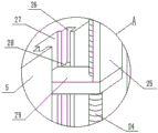
further, the upper end of the upper fixing seat 6 is fixedly connected with a sleeve 38, a buffering rod 39 is arranged in the sleeve 38, the upper end of the buffering rod 39 is fixedly connected with the lower surface of the supporting plate 4, a first spring 40 is sleeved on the outer side of the buffering rod 39, two ends of the first spring 40 are respectively fixedly connected with the lower surface of the base 14 and the upper surface of the sleeve 38, the buffering rod 39 is located on the inner side portion of the sleeve 38 and is fixedly connected with a third sliding block 44, a third sliding groove 41 is formed in the inner wall of the sleeve 38, the third sliding block 44 is slidably arranged in the third sliding groove 41, a sliding rod 43 is slidably sleeved on the third sliding block 44, the sliding rod 43 is fixedly connected in the third sliding groove 41, a second spring 42 is sleeved on the sliding rod 43, the bottom surfaces of the second spring 42 and the third sliding groove 41 and the third sliding block 44 are fixedly connected, and the bottom of the buffering rod 39 is fixedly connected.
In this embodiment, sleeve 38 is fixedly connected to the upper end of upper fixing seat 6, the upper end of sleeve 38 is connected with supporting plate 4 through buffer rod 39 that the activity set up, when rotating second threaded rod 24 and driving supporting plate 4 and upper fixing seat 6 downstream, first spring 40 of buffer rod 39 surface carries out the primary compression, second spring 42 on slide bar 43 carries out the secondary compression after that, fixed third spring 37 carries out the tertiary compression between buffer rod 39 and the sleeve 38 bottom, the cushioning effect that plays this moment, can effectively slow down the ligneous pressure between upper fixing seat 6 and the lower fixing seat 5, prevent that direct rigid contact from causing the timber surface to produce the indentation, especially in comparatively precious wood processing, can effectively play the guard action to the timber surface.
It will be evident to those skilled in the art that the invention is not limited to the details of the foregoing illustrative embodiments, and that the present invention may be embodied in other specific forms without departing from the spirit or essential attributes thereof. The present embodiments are therefore to be considered in all respects as illustrative and not restrictive, the scope of the invention being indicated by the appended claims rather than by the foregoing description, and all changes which come within the meaning and range of equivalency of the claims are therefore intended to be embraced therein. Any reference sign in a claim should not be construed as limiting the claim concerned.
Furthermore, it should be understood that although the present description refers to embodiments, not every embodiment may contain only a single embodiment, and such description is for clarity only, and those skilled in the art should integrate the description, and the embodiments may be combined as appropriate to form other embodiments understood by those skilled in the art.
Claims (10)
1. The multi-angle cutting equipment for wood production comprises a base (14) and is characterized in that a control panel (16) is fixedly mounted at the upper end of the base (14), a power line is connected onto the control panel (16), a fixing plate (7) is fixedly connected to the upper surface of the right side of the base (14), a supporting concave seat (3) is fixedly connected to the left side of the upper surface of the base (14), a screw rod driving device is arranged between the supporting concave seat (3) and the fixing plate (7), and the screw rod driving device comprises a guide rod (8) and a first threaded rod (15); the screw rod driving device is provided with a wood fixing device, the wood fixing device comprises an upper fixing seat (6) and a supporting plate (4) and a lower fixing seat (5), the front end of the lower fixing seat (5) is connected with the guide rod (8) in a sliding mode, and the rear end of the lower fixing seat (5) is in threaded connection with the first threaded rod (15); and a lifting cutting device is arranged on the left side of the upper surface of the base (14).
2. The multi-angle cutting equipment for wood production according to claim 1, wherein the guide rod (8) is fixedly connected between the supporting recess (3) and the fixing plate (7), two ends of the first threaded rod (15) are respectively rotatably connected with the supporting recess (3) and the fixing plate (7), and one end of the first threaded rod (15) rotatably connected with the fixing plate (7) penetrates out of the fixing plate (7).
3. The multi-angle cutting equipment for wood production according to claim 1, wherein one end of the first threaded rod (15) penetrating through the fixing plate (7) is fixedly connected with a driven pulley (9), the driven pulley (9) is connected with a driving pulley (11) through a transmission belt (10), the middle part of the driving pulley (11) is fixedly connected with a driving shaft (12), the driving shaft (12) is connected with an output shaft of a driving motor (13), the driving motor (13) is installed on the upper surface of the base (14), the driving motor (13) is connected with a power line, and the input end of the driving motor (13) is electrically connected with the output end of the control panel (16).
4. The multi-angle cutting equipment for wood production as claimed in claim 1, wherein a sleeve (38) is fixedly connected to the upper end of the upper fixing seat (6), a buffer rod (39) is arranged in the sleeve (38), the upper end of the buffer rod (39) is fixedly connected to the lower surface of the supporting plate (4), a first spring (40) is sleeved on the outer side of the buffer rod (39), two ends of the first spring (40) are respectively fixedly connected to the lower surface of the base (14) and the upper surface of the sleeve (38), and a third sliding block (44) is fixedly connected to the inner side portion of the sleeve (38) of the buffer rod (39).
5. The multi-angle cutting equipment for wood production according to claim 4, wherein a third sliding groove (41) is formed in the inner wall of the sleeve (38), a third sliding block (44) is slidably arranged in the third sliding groove (41), a sliding rod (43) is slidably sleeved on the third sliding block (44), the sliding rod (43) is fixedly connected in the third sliding groove (41), a second spring (42) is sleeved on the sliding rod (43), the second spring (42) is fixedly connected with the bottom surface of the third sliding groove (41) and the bottom surface of the third sliding block (44), and the bottom of the buffer rod (39) is fixedly connected with the bottom of the sleeve (38) through a third spring (37).
6. The multi-angle cutting equipment for wood production according to claim 1, wherein the upper fixing seat (6) is arranged at the upper end of the lower fixing seat (5), an upper arc-shaped groove (21) is formed in the lower surface of the upper fixing seat (6), a lower arc-shaped groove (20) is formed in the upper surface of the lower fixing seat (5), the caliber of the upper arc-shaped groove (21) is smaller than that of the lower arc-shaped groove (20), the right side of the supporting plate (4) is rotatably connected with a second threaded rod (24), a connecting plate (22) is fixedly connected to the side edge of the bottom of the lower fixing seat (5), the lower end of the second threaded rod (24) is rotatably connected with a bearing seat (23) through a bearing, and the bearing seat (23) is fixedly installed on the upper surface.
7. The multi-angle cutting equipment for wood production according to claim 6, characterized in that the second threaded rod (24) is connected with a first sliding block (29) through threads, the upper end of the first sliding block (29) is fixedly connected with a vertical plate (25), the upper end of the vertical plate (25) is fixedly connected with the lower surface of the support plate (4), the side wall of the lower fixing seat (5) is provided with a first sliding groove (27), the first sliding block (29) is arranged in the first sliding groove (27) in a sliding manner, the front side and the rear side of the first sliding block (29) are fixedly connected with second sliding blocks (28), the front inner wall and the rear inner wall of the first sliding groove (27) are provided with a second sliding groove (26), and the second sliding blocks (28) are arranged in the second sliding groove (26) in a sliding manner.
8. The multi-angle cutting equipment for wood production as claimed in claim 1, wherein the lifting and cutting device comprises a support frame (2), the support frame (2) is fixedly installed on the upper surface of the base (14), a lifting cylinder (1) is fixedly installed at the upper end of the support frame (2), a power cord is connected to the lifting cylinder (1), the input end of the lifting cylinder (1) is electrically connected with the output end of the control panel (16), an installation plate (19) is fixedly connected to the output shaft of the lower end of the lifting cylinder (1), a cutting motor (18) is arranged at the lower end of the installation plate (19), a power cord is connected to the cutting motor (18), the input end of the cutting motor (18) is electrically connected with the output end of the control panel (16), and a cutting knife (17) is fixedly connected to the output shaft of the cutting motor (18).
9. The multi-angle cutting apparatus for wood production according to claim 8, both ends fixedly connected with fixed block (30) around the upper surface right side of cutting motor (18), fixedly connected with connecting axle (31) between fixed block (30) of front and back both sides, it is connected with turning block (36) to rotate on connecting axle (31), the upper end of turning block (36) is connected with the lower fixed surface of mounting panel (19), both ends downside fixedly connected with arc (32) around mounting panel (19), it is provided with arc through groove (33) to run through on arc (32), both ends outside fixedly connected with connecting rod (34) around cutting motor (18), connecting rod (34) set up in arc through groove (33), be provided with the external screw thread on the outer wall of connecting rod (34), threaded connection has nut (35) on the external screw thread of connecting rod (34).
10. The multi-angle cutting apparatus for wood production as claimed in any one of claims 1 to 9, wherein the method of using the multi-angle cutting apparatus for wood production comprises the steps of:
step 1: connecting power lines of a cutting motor (18), a lifting cylinder (1), a driving motor (13) and a control panel (16) with an external power supply, and placing wood between a support concave seat (3) and a wood fixing device;
step 2: the cutting motor (18) rotates on the connecting shaft (31) through the rotating block (36), the angle of the cutting motor (18) is changed, after the cutting motor rotates to a proper angle, the nut (35) is tightly attached to the outer surface of the cutting motor (18) through rotating the nut (35), the cutting motor (18) is fixed, and the angle is adjusted;
and step 3: fixing base (6) downstream is gone up in driving through rotating second threaded rod (24) to make and go up fixing base (6) and fix ligneous one end with lower fixing base (5), control driving motor (13), cutting motor (18) and lift cylinder (1) through control panel (16) and carry out work, make timber remove at the upper surface of base (14), the in-process cutting motor (18) of removal drive cutting knife (17) rotate and cut timber.
Priority Applications (1)
| Application Number | Priority Date | Filing Date | Title |
|---|---|---|---|
| CN202011062087.7A CN112123462A (en) | 2020-09-30 | 2020-09-30 | Multi-angle cutting equipment for wood production |
Applications Claiming Priority (1)
| Application Number | Priority Date | Filing Date | Title |
|---|---|---|---|
| CN202011062087.7A CN112123462A (en) | 2020-09-30 | 2020-09-30 | Multi-angle cutting equipment for wood production |
Publications (1)
| Publication Number | Publication Date |
|---|---|
| CN112123462A true CN112123462A (en) | 2020-12-25 |
Family
ID=73843549
Family Applications (1)
| Application Number | Title | Priority Date | Filing Date |
|---|---|---|---|
| CN202011062087.7A Pending CN112123462A (en) | 2020-09-30 | 2020-09-30 | Multi-angle cutting equipment for wood production |
Country Status (1)
| Country | Link |
|---|---|
| CN (1) | CN112123462A (en) |
Cited By (5)
| Publication number | Priority date | Publication date | Assignee | Title |
|---|---|---|---|---|
| CN112659295A (en) * | 2020-12-31 | 2021-04-16 | 安徽美景工艺品有限公司 | Wickerwork stop-motion shearing mechanism |
| CN113787227A (en) * | 2021-09-02 | 2021-12-14 | 邱成 | Cutting equipment for hydraulic engineering |
| CN114016523A (en) * | 2021-11-10 | 2022-02-08 | 生态环境部南京环境科学研究所 | Water and soil conservation is with piling slope structure and ecological prosthetic devices |
| CN115157387A (en) * | 2022-08-09 | 2022-10-11 | 徐州市力王工具有限公司 | Wood working production cutting device |
| CN115319863A (en) * | 2022-08-31 | 2022-11-11 | 徐州市力王工具有限公司 | Cut stable just wood working straight flange machine of convenient regulation |
Citations (5)
| Publication number | Priority date | Publication date | Assignee | Title |
|---|---|---|---|---|
| US4441536A (en) * | 1980-12-22 | 1984-04-10 | Kauko Rautio | Machine for hewing square timbers |
| CN107953283A (en) * | 2017-12-01 | 2018-04-24 | 柳州市钜嘉机械有限公司 | A kind of clamp system of automobile gauge |
| CN108747904A (en) * | 2018-07-13 | 2018-11-06 | 高邮市力博机床附件厂 | A kind of plank processing fixing device with regulatory function |
| CN109732707A (en) * | 2019-02-19 | 2019-05-10 | 杨冬霞 | A kind of Forestry Engineering timber cutter device |
| CN110405859A (en) * | 2019-08-29 | 2019-11-05 | 杨钊銮 | A kind of timber cutter device of adjustable cutting angle |
-
2020
- 2020-09-30 CN CN202011062087.7A patent/CN112123462A/en active Pending
Patent Citations (5)
| Publication number | Priority date | Publication date | Assignee | Title |
|---|---|---|---|---|
| US4441536A (en) * | 1980-12-22 | 1984-04-10 | Kauko Rautio | Machine for hewing square timbers |
| CN107953283A (en) * | 2017-12-01 | 2018-04-24 | 柳州市钜嘉机械有限公司 | A kind of clamp system of automobile gauge |
| CN108747904A (en) * | 2018-07-13 | 2018-11-06 | 高邮市力博机床附件厂 | A kind of plank processing fixing device with regulatory function |
| CN109732707A (en) * | 2019-02-19 | 2019-05-10 | 杨冬霞 | A kind of Forestry Engineering timber cutter device |
| CN110405859A (en) * | 2019-08-29 | 2019-11-05 | 杨钊銮 | A kind of timber cutter device of adjustable cutting angle |
Cited By (5)
| Publication number | Priority date | Publication date | Assignee | Title |
|---|---|---|---|---|
| CN112659295A (en) * | 2020-12-31 | 2021-04-16 | 安徽美景工艺品有限公司 | Wickerwork stop-motion shearing mechanism |
| CN113787227A (en) * | 2021-09-02 | 2021-12-14 | 邱成 | Cutting equipment for hydraulic engineering |
| CN114016523A (en) * | 2021-11-10 | 2022-02-08 | 生态环境部南京环境科学研究所 | Water and soil conservation is with piling slope structure and ecological prosthetic devices |
| CN115157387A (en) * | 2022-08-09 | 2022-10-11 | 徐州市力王工具有限公司 | Wood working production cutting device |
| CN115319863A (en) * | 2022-08-31 | 2022-11-11 | 徐州市力王工具有限公司 | Cut stable just wood working straight flange machine of convenient regulation |
Similar Documents
| Publication | Publication Date | Title |
|---|---|---|
| CN112123462A (en) | Multi-angle cutting equipment for wood production | |
| CN112571547A (en) | Wood cutting equipment for carpenter | |
| CN211250369U (en) | Wood board double-sided thicknessing mechanism | |
| CN204136160U (en) | A kind of Sawing machine travelling carriage | |
| CN112171800A (en) | High-precision wood drilling equipment for furniture processing | |
| CN111645155A (en) | Electric planer with simple force application | |
| CN209615735U (en) | A kind of corner clipping device for wooden boards | |
| CN110883900A (en) | Edge sealing and grooving integrated machine for wood board processing | |
| CN107042554A (en) | Furniture board groover | |
| CN209774235U (en) | Adjustable fixed-angle type timber edge grinding machine | |
| CN108673308A (en) | A kind of woodwork belt sander automatic feed mechanism | |
| CN213290553U (en) | Portable sawing and milling device for wood processing | |
| CN214685967U (en) | Timber fixing device of grinder for plank processing | |
| CN114670097A (en) | Wood working is with burnishing and polishing device | |
| CN213470576U (en) | Grinding device is used in plywood production convenient to operating personnel adjusts | |
| CN210160917U (en) | Efficient trimming machine | |
| CN218428958U (en) | Wood board trimmer | |
| CN113001290A (en) | Surface finish machining system for manufacturing solid wood particle composite board | |
| CN208841099U (en) | Trimmer is used in a kind of processing of timber | |
| CN215618649U (en) | Drilling device for wood processing | |
| CN207290327U (en) | Mitre saw chalker | |
| CN211941286U (en) | Wood pulp fiber sheet cutting device | |
| CN218195714U (en) | Clamping device of woodworking machine tool | |
| CN206748617U (en) | A kind of belt tensioning mechanism of MDF saw cutting device | |
| CN208276652U (en) | A kind of combination plank trimmer |
Legal Events
| Date | Code | Title | Description |
|---|---|---|---|
| PB01 | Publication | ||
| PB01 | Publication | ||
| SE01 | Entry into force of request for substantive examination | ||
| SE01 | Entry into force of request for substantive examination | ||
| RJ01 | Rejection of invention patent application after publication | ||
| RJ01 | Rejection of invention patent application after publication |
Application publication date: 20201225 |