CN112120617A - Cleaning equipment for ceiling dust - Google Patents
Cleaning equipment for ceiling dust Download PDFInfo
- Publication number
- CN112120617A CN112120617A CN202011091682.3A CN202011091682A CN112120617A CN 112120617 A CN112120617 A CN 112120617A CN 202011091682 A CN202011091682 A CN 202011091682A CN 112120617 A CN112120617 A CN 112120617A
- Authority
- CN
- China
- Prior art keywords
- wall
- fixedly arranged
- rotating shaft
- plate
- cavity
- Prior art date
- Legal status (The legal status is an assumption and is not a legal conclusion. Google has not performed a legal analysis and makes no representation as to the accuracy of the status listed.)
- Withdrawn
Links
Images


Classifications
-
- A—HUMAN NECESSITIES
- A47—FURNITURE; DOMESTIC ARTICLES OR APPLIANCES; COFFEE MILLS; SPICE MILLS; SUCTION CLEANERS IN GENERAL
- A47L—DOMESTIC WASHING OR CLEANING; SUCTION CLEANERS IN GENERAL
- A47L11/00—Machines for cleaning floors, carpets, furniture, walls, or wall coverings
- A47L11/38—Machines, specially adapted for cleaning walls, ceilings, roofs, or the like
-
- A—HUMAN NECESSITIES
- A47—FURNITURE; DOMESTIC ARTICLES OR APPLIANCES; COFFEE MILLS; SPICE MILLS; SUCTION CLEANERS IN GENERAL
- A47L—DOMESTIC WASHING OR CLEANING; SUCTION CLEANERS IN GENERAL
- A47L11/00—Machines for cleaning floors, carpets, furniture, walls, or wall coverings
- A47L11/40—Parts or details of machines not provided for in groups A47L11/02 - A47L11/38, or not restricted to one of these groups, e.g. handles, arrangements of switches, skirts, buffers, levers
- A47L11/4036—Parts or details of the surface treating tools
-
- A—HUMAN NECESSITIES
- A47—FURNITURE; DOMESTIC ARTICLES OR APPLIANCES; COFFEE MILLS; SPICE MILLS; SUCTION CLEANERS IN GENERAL
- A47L—DOMESTIC WASHING OR CLEANING; SUCTION CLEANERS IN GENERAL
- A47L11/00—Machines for cleaning floors, carpets, furniture, walls, or wall coverings
- A47L11/40—Parts or details of machines not provided for in groups A47L11/02 - A47L11/38, or not restricted to one of these groups, e.g. handles, arrangements of switches, skirts, buffers, levers
- A47L11/4063—Driving means; Transmission means therefor
- A47L11/4069—Driving or transmission means for the cleaning tools
-
- A—HUMAN NECESSITIES
- A47—FURNITURE; DOMESTIC ARTICLES OR APPLIANCES; COFFEE MILLS; SPICE MILLS; SUCTION CLEANERS IN GENERAL
- A47L—DOMESTIC WASHING OR CLEANING; SUCTION CLEANERS IN GENERAL
- A47L11/00—Machines for cleaning floors, carpets, furniture, walls, or wall coverings
- A47L11/40—Parts or details of machines not provided for in groups A47L11/02 - A47L11/38, or not restricted to one of these groups, e.g. handles, arrangements of switches, skirts, buffers, levers
- A47L11/408—Means for supplying cleaning or surface treating agents
- A47L11/4088—Supply pumps; Spraying devices; Supply conduits
Abstract
The invention discloses a cleaning device for dust on a ceiling, which comprises a machine body, wherein a containing cavity is arranged in the machine body, a trigger mechanism is arranged in the containing cavity, the trigger mechanism comprises a separation plate fixedly arranged between the inner walls of the front side and the rear side of the containing cavity, a fixed shell is fixedly arranged on the inner wall of the lower side of the containing cavity, an extrusion cavity is arranged in the fixed shell, a first slide block is arranged between the inner walls of the left side and the right side of the extrusion cavity in a sliding manner, a first spring is fixedly arranged between the lower end surface of the first slide block and the inner wall of the lower side of the extrusion cavity, a first groove is arranged on the inner wall of the right side of the extrusion cavity, and is positioned on the lower side of the first slide block. And then collected by a collecting mechanism to avoid dust from flying.
Description
Technical Field
The invention relates to the field of sanitation, in particular to a cleaning device for dust on a ceiling.
Background
After the ceiling is used for a long time, dust, stain, spider webs and the like are accumulated on the ceiling, the comfort of life of people is affected, the ceiling is cleaned at present and is often brushed down by using feather dusters, but the brushed dust falls to a bed and clothes of people and is not clean, and therefore equipment is needed to solve the problems.
Disclosure of Invention
The invention aims to provide a ceiling dust cleaning device, which overcomes the problem of dust falling during ceiling cleaning.
The invention is realized by the following technical scheme.
The invention relates to a cleaning device for dust on a ceiling, which comprises a machine body, wherein a containing cavity is arranged in the machine body, a trigger mechanism is arranged in the containing cavity, the trigger mechanism comprises a partition board fixedly arranged between the inner walls on the front side and the rear side of the containing cavity, a fixed shell is fixedly arranged on the inner wall on the lower side of the containing cavity, an extrusion cavity is arranged in the fixed shell, a first slide block is arranged between the inner walls on the left side and the right side of the extrusion cavity in a sliding manner, a first spring is fixedly arranged between the lower end surface of the first slide block and the inner wall on the lower side of the extrusion cavity, a first groove is arranged on the inner wall on the right side of the extrusion cavity, the first groove is positioned on the lower side of the first slide block, a second groove is arranged on the right end surface of the first slide block, an iron block is arranged between the inner walls on the upper side and the lower side of the second groove in a sliding, the magnetic block is positioned on the left side of the second groove, a support rod is fixedly arranged on the upper end face of the first sliding block, the support rod penetrates through the inner wall of the upper side of the extrusion cavity and the upper and lower end faces of the partition plate, a first rotating shaft is rotatably arranged at the upper end of the support rod, and a rotating wheel is fixedly arranged on the first rotating shaft; a fifth spring of the brushing mechanism is arranged in the containing cavity, the fifth spring of the brushing mechanism comprises a first motor fixedly arranged on the lower end surface of the isolation plate, a second rotating shaft is rotatably arranged at the upper end of the first motor, the second rotating shaft penetrates through the upper end surface and the lower end surface of the isolation plate, a driving helical gear is fixedly arranged on the second rotating shaft, a third rotating shaft is rotatably arranged between the inner walls of the front side and the rear side of the containing cavity, the third rotating shaft is positioned on the upper side of the isolation plate, a driven helical gear and a first belt pulley are fixedly arranged on the third rotating shaft, the first belt pulley is positioned on the rear side of the driven helical gear, the driven helical gear is meshed with the driving helical gear, a fourth rotating shaft is rotatably arranged between the inner walls of the front side and the rear side of the containing cavity, the fourth rotating shaft is positioned on the right side of the third rotating shaft, a second belt pulley, a brush wheel and a third belt pulley are fixedly arranged on, the second belt wheel is connected with the first belt wheel through a first belt; the collecting cavity is internally provided with a collecting mechanism, the collecting mechanism comprises a supporting plate fixedly arranged between the lower end surface of the isolating plate and the lower inner wall of the collecting cavity, the supporting plate is positioned on the right side of the fixed shell, the lower inner wall of the collecting cavity is fixedly provided with a fixed plate, a guide plate is fixedly arranged between the front inner wall and the rear inner wall of the collecting cavity, the guide plate is positioned between the fixed plate and the isolating plate, the lower inner wall of the collecting cavity is rotatably provided with a fifth rotating shaft, the fifth rotating shaft is positioned between the supporting plate and the fixed plate, a bearing plate is fixedly arranged between the supporting plate and the fixed plate, the fifth rotating shaft is fixedly provided with a driving helical gear, a first fan blade and a centrifugal wheel, the first fan blade is positioned between the driving helical gear and the centrifugal wheel, the front inner wall of the collecting cavity is rotatably provided with a sixth rotating shaft, and the sixth rotating shaft is fixedly provided with, the transmission helical gear is positioned at the rear side of the fourth belt pulley, the fourth belt pulley is connected with the third belt pulley through a second belt, the transmission helical gear is meshed with the driving helical gear, the centrifugal wheel is positioned at the lower side of the bearing plate, two third grooves are symmetrically arranged in the centrifugal wheel in a left-right mode by taking the fifth rotating shaft as a center, a second sliding block is arranged between the upper inner wall and the lower inner wall of each third groove in a sliding mode, a third spring is fixedly arranged between the second sliding block and the third groove, the third spring is fixedly arranged between the second sliding block and the inner wall of the side, close to the fifth rotating shaft, of the third groove, the left end face of the fixing plate is fixedly provided with a second motor, the second motor is positioned at the lower side of the bearing plate, a starter is fixedly arranged at the left end of the second motor, a seventh rotating shaft is rotatably arranged at the upper end of the second motor, the seventh, the seventh pivot runs through terminal surface about the third slider, the inside threaded connection of third slider the seventh pivot, the fixed baffle that is equipped with of third slider left end face, the baffle up end pastes closely the division board with the deflector lower extreme, the fixed plate that is equipped with is fixed to the fixed plate left end, the terminal surface is equipped with the torque groove under the protective housing, it is equipped with the torsional spring to rotate between the side inner wall about the torque groove, the seventh pivot runs through torque groove upside inner wall, the fixed reel that is equipped with in the seventh pivot.
Preferably, the trigger mechanism further comprises a water storage tank fixedly arranged on the inner wall of the lower side of the containing cavity, a fourth sliding block is arranged at the upper end of the water storage tank in a sliding mode, a plug is fixedly arranged on the left end face of the fourth sliding block, a connecting seat is fixedly arranged on the right end face of the fourth sliding block, the connecting seat is connected with the supporting rod through a first connecting rod, a power supply block and a water pump are fixedly arranged on the upper end of the water storage tank, the power supply block is located between the water pump and the plug, and the water pump, the power supply block and the first motor are connected through electric wires.
Preferably, the brushing mechanism further comprises a spray head fixedly arranged on the upper end face of the isolation plate, the spray head is connected with the water pump through a water pipe, and the water pipe penetrates through the upper end face and the lower end face of the isolation plate.
Preferably, the collecting mechanism further comprises a connecting plate fixedly arranged between the right end face of the fixing plate and the inner wall of the right side of the containing cavity, a transition block is fixedly arranged on the connecting plate, a fourth groove is arranged in the transition block, a fifth slider is slidably arranged between the upper inner wall and the lower inner wall of the fourth groove, a fourth spring is fixedly arranged between the fifth slider and the inner wall of the right side of the fourth groove, the left end face of the fifth slider is connected with the reel through a string, the string penetrates through the inner wall of the left side of the fourth groove, a supporting shell is fixedly arranged on the inner wall of the right side of the containing cavity, the supporting shell is positioned on the upper side of the connecting plate, a pressure cavity is arranged in the supporting shell, a sixth slider is slidably arranged between the upper inner wall and the lower inner wall of the pressure cavity, a fifth spring is fixedly arranged between the right end face of the sixth slider and the inner wall of the right side of, rotate on the first fixed axle and be equipped with the extrusion wheel, it is fixed between the inboard wall of chamber front and back side to accomodate to be equipped with the second fixed axle, it is equipped with the suction wheel to rotate on the second fixed axle, the suction wheel with the extrusion wheel laminating, the fixed plate with it is fixed between the inboard wall of chamber right side to accomodate, the breather pipe runs through terminal surface about the fixed plate with accomodate chamber right side inner wall.
Preferably, a base is arranged at the lower side of the machine body, a placement cavity is arranged in the base, a third motor is fixedly arranged on the inner wall of the lower side of the placement cavity, an eighth rotating shaft is rotatably arranged at the left end of the third motor, an eighth sliding block and a seventh sliding block are slidably arranged on the inner wall of the lower side of the placement cavity, the seventh sliding block and the eighth sliding block are distributed left and right, the eighth rotating shaft penetrates through the left and right end faces of the seventh sliding block and the eighth sliding block, the seventh sliding block and the eighth sliding block are internally and threadedly connected with the eighth rotating shaft, a first base and a second base are respectively fixedly arranged on the upper end faces of the seventh sliding block and the eighth sliding block, a push plate is slidably arranged between the left and right inner walls of the placement cavity, two third bases are fixedly arranged on the lower end face of the push plate, the two third bases are distributed left and right, and the two third bases are respectively connected with the first base and the, the upper end face of the push plate is fixedly provided with a supporting block, the supporting block penetrates through the inner wall of the upper side of the placement cavity, and the upper end face of the supporting block is fixedly arranged on the lower end face of the machine body.
The invention has the beneficial effects that: when the cleaning machine is used, the working machine body is lifted to be close to a ceiling to cover the cleaned part, so that dust is prevented from falling to affect the indoor environment, then cleaning agent is sprayed on the ceiling and is scrubbed, and then the cleaning machine body is collected by the collecting mechanism to prevent the dust from floating.
Drawings
In order to more clearly illustrate the embodiments of the invention or the technical solutions in the prior art, the drawings used in the description of the embodiments or the prior art will be briefly described below, and it is obvious that the drawings in the following description are only some embodiments of the invention, and it is obvious for those skilled in the art that other drawings can be obtained based on these drawings without creative efforts.
FIG. 1 is a schematic structural view of an example of the present invention;
FIG. 2 is a schematic view of the embodiment of the present invention in the direction of A-A in FIG. 1;
FIG. 3 is a schematic view of the embodiment of the present invention in the direction B-B in FIG. 1;
FIG. 4 is an enlarged schematic view of the embodiment of the present invention at C in FIG. 1.
Detailed Description
The invention will now be described in detail with reference to fig. 1-4, wherein for ease of description the orientations described hereinafter are now defined as follows: the up, down, left, right, and front-back directions described below correspond to the up, down, left, right, and front-back directions in the projection relationship of fig. 1 itself.
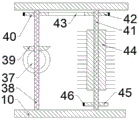
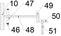
The ceiling dust cleaning device shown in fig. 1-4 includes a device body 10, a receiving chamber 11 is provided in the device body 10, a triggering mechanism 90 is provided in the receiving chamber 11, the triggering mechanism 90 includes a partition plate 12 fixedly provided between front and rear inner walls of the receiving chamber 11, a fixing housing 14 is fixedly provided on an inner wall of a lower side of the receiving chamber 11, an extrusion chamber 15 is provided in the fixing housing 14, a first slider 16 is slidably provided between left and right inner walls of the extrusion chamber 15, a first spring 17 is fixedly provided between a lower end surface of the first slider 16 and the lower inner wall of the extrusion chamber 15, a first groove 18 is provided on the inner wall of the right side of the extrusion chamber 15, the first groove 18 is provided on the lower side of the first slider 16, a second groove 19 is provided on a right end surface of the first slider 16, an iron block 21 is slidably provided between the upper and lower inner walls of the second groove 19, a second spring 20 is fixedly provided between a left end surface of the iron block 21 and the left inner wall of the second groove 19, a magnetic block 22 is fixedly arranged in the first slider 16, the magnetic block 22 is positioned on the left side of the second groove 19, a support rod 23 is fixedly arranged on the upper end surface of the first slider 16, the support rod 23 penetrates through the inner wall of the upper side of the extrusion cavity 15 and the upper and lower end surfaces of the partition plate 12, a first rotating shaft 24 is rotatably arranged at the upper end of the support rod 23, a rotating wheel 25 is fixedly arranged on the first rotating shaft 24, the rotating wheel 25 is pushed by a ceiling, the support rod 25 pushes the support rod 23, the support rod 23 pushes the first slider 16, the second groove 19 pushes the iron block 21 to slide, and the iron block 21 blocks the first groove 18; accomodate and be equipped with scrubbing mechanism fifth spring 81 in the chamber 11, scrubbing mechanism fifth spring 81 includes the first motor 34 that the terminal surface was fixed to be equipped with under the division board 12, first motor 34 upper end is rotated and is equipped with second pivot 36, second pivot 36 runs through terminal surface about the division board 12, the fixed drive helical gear 37 that is equipped with in second pivot 36, it is equipped with third pivot 38 to accomodate the rotation of chamber 11 front and back side inner wall, third pivot 38 is located division board 12 upside, fixed driven helical gear 39 and the first band pulley 40 of being equipped with in third pivot 38, first band pulley 40 is located driven helical gear 39 rear side, driven helical gear 39 with drive helical gear 37 meshes, it is equipped with fourth pivot 41 to accomodate the rotation of chamber 11 front and back side inner wall, fourth pivot 41 is located third pivot 38 right side, fixed second band pulley 42, the last second of being equipped with of fourth pivot 41, A brush wheel 44 and a third belt wheel 45, the brush wheel 44 is located between the second belt wheel 42 and the third belt wheel 45, the second belt wheel 42 is connected with the first belt wheel 40 through a first belt 43, the first motor 34 drives the second rotating shaft 36 to rotate, the second rotating shaft 36 drives the driving bevel gear 37 to rotate, the driving bevel gear 37 drives the driven bevel gear 39 to rotate through meshing with the driven bevel gear 39, the driven bevel gear 39 drives the third rotating shaft 38 and the first belt wheel 40 to rotate, the first belt wheel 40 drives the second belt wheel 42 to rotate through the first belt 43, the second belt wheel 42 drives the fourth rotating shaft 41 to rotate, and the fourth rotating shaft 41 drives the brush wheel 44 and the third belt wheel 45 to rotate; a collecting mechanism 92 is arranged in the containing cavity 11, the collecting mechanism 92 comprises a supporting plate 52 fixedly arranged between the lower end face of the isolating plate 12 and the lower inner wall of the containing cavity 11, the supporting plate 52 is positioned at the right side of the fixing shell 14, a fixing plate 54 is fixedly arranged on the lower inner wall of the containing cavity 11, a guide plate 68 is fixedly arranged between the front inner wall and the rear inner wall of the containing cavity 11, the guide plate 68 is positioned between the fixing plate 54 and the isolating plate 12, a fifth rotating shaft 51 is rotatably arranged on the lower inner wall of the containing cavity 11, the fifth rotating shaft 51 is positioned between the supporting plate 52 and the fixing plate 54, a bearing plate 56 is fixedly arranged between the supporting plate 52 and the fixing plate 54, a driving bevel gear 50, a first fan blade 53 and a centrifugal wheel 100 are fixedly arranged on the fifth rotating shaft 51, and the first fan blade 53 is positioned between the driving bevel gear 50 and the centrifugal wheel 100, a sixth rotating shaft 48 is rotatably arranged on the inner wall of the front side of the accommodating cavity 11, a fourth belt wheel 47 and a transmission bevel gear 49 are fixedly arranged on the sixth rotating shaft 48, the transmission bevel gear 49 is positioned at the rear side of the fourth belt wheel 47, the fourth belt wheel 47 is connected with the third belt wheel 45 through a second belt 46, the transmission bevel gear 49 is engaged with the driving bevel gear 50, the centrifugal wheel 100 is positioned at the lower side of the bearing plate 56, two third grooves 59 are symmetrically arranged in the centrifugal wheel 100 in a left-right manner by taking the fifth rotating shaft 51 as a center, a second slider 60 is arranged between the upper inner wall and the lower inner wall of each third groove 59 in a sliding manner, a third spring 61 is fixedly arranged between the second slider 60 and the third groove 59 close to the inner wall of the fifth rotating shaft 51, a second motor 55 is fixedly arranged on the left end face of the fixing plate 54, and the second motor 55 is positioned at the lower side of the bearing plate 56, a starter 58 is fixedly arranged at the left end of the second motor 55, a seventh rotating shaft 57 is rotatably arranged at the upper end of the second motor 55, the seventh rotating shaft 57 penetrates through the upper end surface and the lower end surface of the bearing plate 56, a third sliding block 63 is slidably arranged at the left end surface of the fixing plate 54, the seventh rotating shaft 57 penetrates through the upper end surface and the lower end surface of the third sliding block 63, the seventh rotating shaft 57 is connected with the third rotating shaft 63 through internal threads, a baffle plate 62 is fixedly arranged at the left end surface of the third sliding block 63, the upper end surface of the baffle plate 62 is close to the lower ends of the partition plate 12 and the guide plate 68, the fixing plate 54 is fixedly arranged at the left end surface of the fixing plate 54, a torsion groove 65 is arranged at the lower end surface of the protective housing 64, a torsion spring 66 is rotatably arranged between the left inner wall and the right inner wall of the torsion groove 65, the seventh rotating shaft 57 penetrates through the upper inner wall of the torsion groove 65, the driving bevel gear 49 drives the driving bevel gear 50 to rotate through meshing with the driving bevel gear 50, the driving bevel gear 50 drives the fifth rotating shaft 51 to rotate, the fifth rotating shaft 51 drives the supporting plate 52 and the centrifugal wheel 100 to rotate, the centrifugal wheel 100 rotates and throws out the second sliding block 60, the second sliding block 60 triggers the starter 58, the second motor 55 drives the seventh rotating shaft 57 to rotate, the seventh rotating shaft 57 drives the third sliding block 63 to slide through threaded connection, the third sliding block 63 drives the baffle 62 to slide, and the seventh rotating shaft 57 drives the reel 67 to rotate.
Beneficially, the trigger mechanism 90 further includes a water storage tank 13 fixedly disposed on the inner wall of the lower side of the accommodating cavity 11, a fourth slider 28 is slidably disposed at the upper end of the water storage tank 13, a plug 29 is fixedly disposed on the left end face of the fourth slider 28, a connecting seat 27 is fixedly disposed on the right end face of the fourth slider 28, the connecting seat 27 is connected to the support rod 23 through a first connecting rod 26, a power supply block 30 and a water pump 31 are fixedly disposed at the upper end of the water storage tank 13, the power supply block 30 is located between the water pump 31 and the plug 29, and the water pump 31, the power supply block 30 and the first motor 34 are connected through an electric wire 35.
Advantageously, the brushing mechanism 91 further comprises a spray head 33 fixedly arranged on the upper end surface of the isolation plate 12, the spray head 33 is connected with the water pump 31 through a water pipe 32, and the water pipe 32 penetrates through the upper and lower end surfaces of the isolation plate 12.
Advantageously, the collecting mechanism 92 further comprises a connecting plate 69 fixedly arranged between the right end surface of the fixing plate 54 and the right inner wall of the receiving cavity 11, a transition block 70 is fixedly arranged on the connecting plate 69, a fourth groove 71 is arranged in the transition block 70, a fifth slider 72 is slidably arranged between the upper inner wall and the lower inner wall of the fourth groove 71, a fourth spring 73 is fixedly arranged between the fifth slider 72 and the right inner wall of the fourth groove 71, the left end surface of the fifth slider 72 is connected with the reel 67 through a string 74, the string 74 penetrates through the left inner wall of the fourth groove 71, a supporting shell 78 is fixedly arranged on the right inner wall of the receiving cavity 11, the supporting shell 78 is positioned on the upper side of the connecting plate 69, a pressure cavity 79 is arranged in the supporting shell 78, a sixth slider 80 is slidably arranged between the upper inner wall and the lower inner wall of the pressure cavity 79, a fifth spring 81 is fixedly arranged between the right end surface of the sixth slider 80 and the right inner wall of the pressure cavity 79, sixth slider 80 left end is fixed and is equipped with first fixed axle 82, it is equipped with extrusion wheel 83 to rotate on the first fixed axle 82, it is fixed and is equipped with second fixed axle 76 to accomodate between the chamber 11 front and back side inner wall, it is equipped with water sucking wheel 77 to rotate on the second fixed axle 76, water sucking wheel 77 with extrusion wheel 83 laminates, fixed plate 54 with accomodate fixed being equipped with breather pipe 75 between the chamber 11 right side inner wall, breather pipe 75 runs through terminal surface about fixed plate 54 with accomodate chamber 11 right side inner wall.
Beneficially, a base 85 is disposed on the lower side of the machine body 10, a placement cavity 86 is disposed in the base 85, a third motor 87 is fixedly disposed on the inner wall of the lower side of the placement cavity 86, an eighth rotating shaft 94 is rotatably disposed at the left end of the third motor 87, an eighth sliding block 88 and a seventh sliding block 95 are slidably disposed on the inner wall of the lower side of the placement cavity 86, the seventh sliding block 95 and the eighth sliding block 88 are distributed left and right, the eighth rotating shaft 94 penetrates through the left and right end surfaces of the seventh sliding block 95 and the eighth sliding block 88, the eighth rotating shaft 94 is threadedly connected inside the seventh sliding block 95 and the eighth sliding block 88, a first base 96 and a second base 89 are respectively fixedly disposed on the upper end surfaces of the seventh sliding block 95 and the eighth sliding block 88, a push plate 99 is slidably disposed between the left and right inner walls of the placement cavity 86, two third bases 97 are fixedly disposed on the lower end surface of the push plate 99, and two third bases, the two third bases 97 are connected with the first base 96 and the second base 89 through a second connecting rod 98 respectively, a supporting block 84 is fixedly arranged on the upper end surface of the push plate 99, the supporting block 84 penetrates through the inner wall of the upper side of the mounting cavity 86, and the upper end surface of the supporting block 84 is fixedly arranged on the lower end surface of the machine body 10.
In the initial state, the second spring 20, the third spring 61, the fourth spring 73, and the torsion spring 66 are in the normal state, and the first spring 17 and the fifth spring 81 are in the compressed state.
When the cleaning machine is used, the third motor 87 is started, the third motor 87 drives the eighth rotating shaft 94 to rotate, the eighth rotating shaft 94 drives the seventh sliding block 95 and the eighth sliding block 88 to slide through threaded connection, the seventh sliding block 95 and the eighth sliding block 88 push the push plate 99 to slide upwards through the second connecting rod 98, the push plate 99 slides upwards to jack up the supporting block 84, the supporting block 84 jacks up the machine body 10 to enable the machine body 10 to be close to the ceiling, the ceiling pushes the rotating wheel 25, the rotating wheel 25 pushes the supporting rod 23, the supporting rod 23 pushes the first sliding block 16, the second groove 19 pushes the iron block 21 to slide, the iron block 21 blocks the first groove 18, the supporting rod 23 pushes the fourth sliding block 28 to slide through the first connecting rod 26, the fourth sliding block 28 drives the plug 29 to slide and insert into the power supply block 30, the circuit is powered on, the water pump 31 drives the cleaning agent to be sprayed out from the spray head 33 through the water conveying pipe 32, the second rotating shaft 36 drives the driving bevel gear 37 to rotate, the driving bevel gear 37 drives the driven bevel gear 39 to rotate by meshing with the driven bevel gear 39, the driven bevel gear 39 drives the third rotating shaft 38 and the first belt pulley 40 to rotate, the first belt pulley 40 drives the second belt pulley 42 to rotate by the first belt 43, the second belt pulley 42 drives the fourth rotating shaft 41 to rotate, the fourth rotating shaft 41 drives the brush wheel 44 and the third belt pulley 45 to rotate, the brush wheel 44 rotates to brush the ceiling, the third belt pulley 45 drives the fourth belt pulley 47 to rotate by the second belt 46, the fourth belt pulley 47 rotates to drive the sixth rotating shaft 48 and the driving bevel gear 49 to rotate, the driving bevel gear 49 drives the driving bevel gear 50 to rotate by meshing with the driving bevel gear 50, the driving bevel gear 50 drives the fifth rotating shaft 51 to rotate, the fifth rotating shaft 51 drives the support plate 52 and the centrifugal wheel 100 to rotate, the centrifugal wheel 100 rotates to throw out the second slider 60, the second slider 60 triggers the starter 58, the second motor 55 drives the seventh rotating shaft 57 to rotate, the seventh rotating shaft 57 drives the third slider 63 to slide through threaded connection, the third slider 63 drives the baffle 62 to slide, the opening is opened, the first fan blade 53 rotates to suck dust, the water suction wheel 77 is attached to a ceiling to rotate to absorb redundant moisture, the extrusion wheel 83 rotates to extrude the water suction wheel 77, the seventh rotating shaft 57 drives the reel 67 to rotate, the reel 67 rotates to wind the string 74, the string 74 pulls the fifth slider 72 to slide to open the opening, and extruded sewage flows in from the opening.
The above embodiments are merely illustrative of the technical ideas and features of the present invention, and the purpose thereof is to enable those skilled in the art to understand the contents of the present invention and implement the present invention, and not to limit the protection scope of the present invention. All equivalent changes and modifications made according to the spirit of the present invention should be covered within the protection scope of the present invention.
Claims (5)
1. A cleaning apparatus for ceiling dust, includes the organism, its characterized in that: a containing cavity is arranged in the machine body, a trigger mechanism is arranged in the containing cavity and comprises a partition plate fixedly arranged between the front inner wall and the rear inner wall of the containing cavity, a fixed shell is fixedly arranged on the lower inner wall of the containing cavity, an extrusion cavity is arranged in the fixed shell, a first slider is arranged between the left inner wall and the right inner wall of the extrusion cavity in a sliding manner, a first spring is fixedly arranged between the lower end surface of the first slider and the lower inner wall of the extrusion cavity, a first groove is arranged on the inner wall of the right side of the extrusion cavity, the first groove is positioned on the lower side of the first slider, a second groove is arranged on the right end surface of the first slider, an iron block is arranged between the upper inner wall and the lower inner wall of the second groove in a sliding manner, a second spring is fixedly arranged between the left end surface of the iron block and the inner wall of the left side of the second groove, a magnetic block is fixedly arranged in the first slider, the left, the supporting rod penetrates through the inner wall of the upper side of the extrusion cavity and the upper end face and the lower end face of the isolation plate, a first rotating shaft is rotatably arranged at the upper end of the supporting rod, and a rotating wheel is fixedly arranged on the first rotating shaft; a fifth spring of the brushing mechanism is arranged in the containing cavity, the fifth spring of the brushing mechanism comprises a first motor fixedly arranged on the lower end surface of the isolation plate, a second rotating shaft is rotatably arranged at the upper end of the first motor, the second rotating shaft penetrates through the upper end surface and the lower end surface of the isolation plate, a driving helical gear is fixedly arranged on the second rotating shaft, a third rotating shaft is rotatably arranged between the inner walls of the front side and the rear side of the containing cavity, the third rotating shaft is positioned on the upper side of the isolation plate, a driven helical gear and a first belt pulley are fixedly arranged on the third rotating shaft, the first belt pulley is positioned on the rear side of the driven helical gear, the driven helical gear is meshed with the driving helical gear, a fourth rotating shaft is rotatably arranged between the inner walls of the front side and the rear side of the containing cavity, the fourth rotating shaft is positioned on the right side of the third rotating shaft, a second belt pulley, a brush wheel and a third belt pulley are fixedly arranged on, the second belt wheel is connected with the first belt wheel through a first belt; the collecting cavity is internally provided with a collecting mechanism, the collecting mechanism comprises a supporting plate fixedly arranged between the lower end surface of the isolating plate and the lower inner wall of the collecting cavity, the supporting plate is positioned on the right side of the fixed shell, the lower inner wall of the collecting cavity is fixedly provided with a fixed plate, a guide plate is fixedly arranged between the front inner wall and the rear inner wall of the collecting cavity, the guide plate is positioned between the fixed plate and the isolating plate, the lower inner wall of the collecting cavity is rotatably provided with a fifth rotating shaft, the fifth rotating shaft is positioned between the supporting plate and the fixed plate, a bearing plate is fixedly arranged between the supporting plate and the fixed plate, the fifth rotating shaft is fixedly provided with a driving helical gear, a first fan blade and a centrifugal wheel, the first fan blade is positioned between the driving helical gear and the centrifugal wheel, the front inner wall of the collecting cavity is rotatably provided with a sixth rotating shaft, and the sixth rotating shaft is fixedly provided with, the transmission helical gear is positioned at the rear side of the fourth belt pulley, the fourth belt pulley is connected with the third belt pulley through a second belt, the transmission helical gear is meshed with the driving helical gear, the centrifugal wheel is positioned at the lower side of the bearing plate, two third grooves are symmetrically arranged in the centrifugal wheel in a left-right mode by taking the fifth rotating shaft as a center, a second sliding block is arranged between the upper inner wall and the lower inner wall of each third groove in a sliding mode, a third spring is fixedly arranged between the second sliding block and the third groove, the third spring is fixedly arranged between the second sliding block and the inner wall of the side, close to the fifth rotating shaft, of the third groove, the left end face of the fixing plate is fixedly provided with a second motor, the second motor is positioned at the lower side of the bearing plate, a starter is fixedly arranged at the left end of the second motor, a seventh rotating shaft is rotatably arranged at the upper end of the second motor, the seventh, the seventh pivot runs through terminal surface about the third slider, the inside threaded connection of third slider the seventh pivot, the fixed baffle that is equipped with of third slider left end face, the baffle up end pastes closely the division board with the deflector lower extreme, the fixed plate that is equipped with is fixed to the fixed plate left end, the terminal surface is equipped with the torque groove under the protective housing, it is equipped with the torsional spring to rotate between the side inner wall about the torque groove, the seventh pivot runs through torque groove upside inner wall, the fixed reel that is equipped with in the seventh pivot.
2. A ceiling dust cleaning apparatus according to claim 1, wherein: the trigger mechanism further comprises a water storage tank fixedly arranged on the inner wall of the lower side of the containing cavity, a fourth sliding block is arranged at the upper end of the water storage tank in a sliding mode, a plug is fixedly arranged on the left end face of the fourth sliding block, a connecting seat is fixedly arranged on the right end face of the fourth sliding block, the connecting seat is connected with the supporting rod through a first connecting rod, a power supply block and a water pump are fixedly arranged at the upper end of the water storage tank, the power supply block is located between the water pump and the plug, and the water pump, the power supply block and the first motor are connected through electric wires.
3. A ceiling dust cleaning apparatus according to claim 1, wherein: the brushing mechanism further comprises a spray head fixedly arranged on the upper end face of the isolation plate, the spray head is connected with the water pump through a water pipe, and the water pipe penetrates through the upper end face and the lower end face of the isolation plate.
4. A ceiling dust cleaning apparatus according to claim 1, wherein: the collecting mechanism further comprises a connecting plate fixedly arranged between the right end face of the fixing plate and the inner wall of the right side of the containing cavity, a transition block is fixedly arranged on the connecting plate, a fourth groove is arranged in the transition block, a fifth slider is arranged between the inner wall of the upper side and the inner wall of the lower side of the fourth groove in a sliding manner, a fourth spring is fixedly arranged between the fifth slider and the inner wall of the right side of the fourth groove, the left end face of the fifth slider is connected with the reel through a thin rope, the thin rope penetrates through the inner wall of the left side of the fourth groove, a supporting shell is fixedly arranged on the inner wall of the right side of the containing cavity, the supporting shell is positioned on the upper side of the connecting plate, a pressure cavity is arranged in the supporting shell, a sixth slider is arranged between the inner wall of the upper side and the lower side of the pressure cavity in a sliding manner, a fifth spring is fixedly arranged between, rotate on the first fixed axle and be equipped with the extrusion wheel, it is fixed between the inboard wall of chamber front and back side to accomodate to be equipped with the second fixed axle, it is equipped with the suction wheel to rotate on the second fixed axle, the suction wheel with the extrusion wheel laminating, the fixed plate with it is fixed between the inboard wall of chamber right side to accomodate, the breather pipe runs through terminal surface about the fixed plate with accomodate chamber right side inner wall.
5. A ceiling dust cleaning apparatus according to claim 1, wherein: a base is arranged at the lower side of the machine body, a mounting cavity is arranged in the base, a third motor is fixedly arranged on the inner wall of the lower side of the mounting cavity, an eighth rotating shaft is arranged at the left end of the third motor in a rotating manner, an eighth sliding block and a seventh sliding block are arranged on the inner wall of the lower side of the mounting cavity in a sliding manner, the seventh sliding block and the eighth sliding block are distributed left and right, the eighth rotating shaft penetrates through the left and right end surfaces of the seventh sliding block and the eighth sliding block, the seventh sliding block is connected with the eighth rotating shaft through the inner thread of the eighth sliding block, a first base and a second base are respectively fixedly arranged on the upper end surfaces of the seventh sliding block and the eighth sliding block, a push plate is arranged between the left and right inner walls of the mounting cavity in a sliding manner, two third bases are fixedly arranged on the lower end surface of the push plate, the two third bases are distributed left and right, and the two, the upper end face of the push plate is fixedly provided with a supporting block, the supporting block penetrates through the inner wall of the upper side of the placement cavity, and the upper end face of the supporting block is fixedly arranged on the lower end face of the machine body.
Priority Applications (1)
| Application Number | Priority Date | Filing Date | Title |
|---|---|---|---|
| CN202011091682.3A CN112120617A (en) | 2020-10-13 | 2020-10-13 | Cleaning equipment for ceiling dust |
Applications Claiming Priority (1)
| Application Number | Priority Date | Filing Date | Title |
|---|---|---|---|
| CN202011091682.3A CN112120617A (en) | 2020-10-13 | 2020-10-13 | Cleaning equipment for ceiling dust |
Publications (1)
| Publication Number | Publication Date |
|---|---|
| CN112120617A true CN112120617A (en) | 2020-12-25 |
Family
ID=73854023
Family Applications (1)
| Application Number | Title | Priority Date | Filing Date |
|---|---|---|---|
| CN202011091682.3A Withdrawn CN112120617A (en) | 2020-10-13 | 2020-10-13 | Cleaning equipment for ceiling dust |
Country Status (1)
| Country | Link |
|---|---|
| CN (1) | CN112120617A (en) |
Cited By (3)
| Publication number | Priority date | Publication date | Assignee | Title |
|---|---|---|---|---|
| CN112545403A (en) * | 2020-12-30 | 2021-03-26 | 南京丝兰芙商贸有限公司 | Automatic wall and ceiling sweeper |
| CN112976009A (en) * | 2021-03-23 | 2021-06-18 | 安徽商贸职业技术学院 | Cleaning robot for lighting ceiling |
| CN114210651A (en) * | 2021-11-12 | 2022-03-22 | 中建材蚌埠玻璃工业设计研究院有限公司 | Automatic dust removal energy-saving display panel |
-
2020
- 2020-10-13 CN CN202011091682.3A patent/CN112120617A/en not_active Withdrawn
Cited By (4)
| Publication number | Priority date | Publication date | Assignee | Title |
|---|---|---|---|---|
| CN112545403A (en) * | 2020-12-30 | 2021-03-26 | 南京丝兰芙商贸有限公司 | Automatic wall and ceiling sweeper |
| CN112545403B (en) * | 2020-12-30 | 2021-10-26 | 德清县德创智能技术有限公司 | Automatic wall and ceiling sweeper |
| CN112976009A (en) * | 2021-03-23 | 2021-06-18 | 安徽商贸职业技术学院 | Cleaning robot for lighting ceiling |
| CN114210651A (en) * | 2021-11-12 | 2022-03-22 | 中建材蚌埠玻璃工业设计研究院有限公司 | Automatic dust removal energy-saving display panel |
Similar Documents
| Publication | Publication Date | Title |
|---|---|---|
| CN112120617A (en) | Cleaning equipment for ceiling dust | |
| CA2618090A1 (en) | Vacuum cleaner | |
| CN205433582U (en) | Improvement formula robot of sweeping floor | |
| CN210795171U (en) | Coiling apparatus is used in toilet paper production | |
| CN202568066U (en) | Cleaning device for slide groove | |
| CN213345520U (en) | Intelligence wall dust cleaning device for building | |
| CN107440317A (en) | Multifunctional cleaning rifle | |
| CN213034239U (en) | Grinding device is used in building floor production with dust removal function | |
| CN215424381U (en) | Glass curtain wall with self-cleaning function | |
| CN213155742U (en) | Automatic shoe brushing device | |
| CN110936391B (en) | Maintenance robot for vertical bamboo flute musical instrument | |
| CN209252715U (en) | A kind of toilet cleaning device | |
| CN111824573A (en) | Prevent losing dustless USB flash disk equipment of storing | |
| CN216574392U (en) | A shell cleaning device for dry-type transformer | |
| CN217013841U (en) | Small-size plane cleaning robot | |
| CN112656281A (en) | Window cleaning equipment with solar light screen | |
| CN113876247B (en) | Automatic dust collector is collected to change ash that falls | |
| CN217013840U (en) | Plane cleaning robot | |
| CN219645630U (en) | Pet dust collector | |
| CN220892467U (en) | Ventilation equipment with noise reduction function | |
| CN212066634U (en) | Power assembly of mopping machine and mopping machine | |
| CN211155526U (en) | Suspension type glass curtain wall cleaning device | |
| CN218728902U (en) | Computer case with micro substrate | |
| CN215499979U (en) | Novel LED power supply | |
| CN217771715U (en) | Anti-falling nail ash collecting device |
Legal Events
| Date | Code | Title | Description |
|---|---|---|---|
| PB01 | Publication | ||
| PB01 | Publication | ||
| SE01 | Entry into force of request for substantive examination | ||
| SE01 | Entry into force of request for substantive examination | ||
| WW01 | Invention patent application withdrawn after publication | ||
| WW01 | Invention patent application withdrawn after publication |
Application publication date: 20201225 |