CN112109341B - Composite blade and method for forming composite blade - Google Patents
Composite blade and method for forming composite blade Download PDFInfo
- Publication number
- CN112109341B CN112109341B CN202010097748.3A CN202010097748A CN112109341B CN 112109341 B CN112109341 B CN 112109341B CN 202010097748 A CN202010097748 A CN 202010097748A CN 112109341 B CN112109341 B CN 112109341B
- Authority
- CN
- China
- Prior art keywords
- blade
- root
- laminate
- laminated body
- composite
- Prior art date
- Legal status (The legal status is an assumption and is not a legal conclusion. Google has not performed a legal analysis and makes no representation as to the accuracy of the status listed.)
- Active
Links
Images


Classifications
-
- F—MECHANICAL ENGINEERING; LIGHTING; HEATING; WEAPONS; BLASTING
- F01—MACHINES OR ENGINES IN GENERAL; ENGINE PLANTS IN GENERAL; STEAM ENGINES
- F01D—NON-POSITIVE DISPLACEMENT MACHINES OR ENGINES, e.g. STEAM TURBINES
- F01D5/00—Blades; Blade-carrying members; Heating, heat-insulating, cooling or antivibration means on the blades or the members
- F01D5/12—Blades
- F01D5/28—Selecting particular materials; Particular measures relating thereto; Measures against erosion or corrosion
- F01D5/282—Selecting composite materials, e.g. blades with reinforcing filaments
-
- B—PERFORMING OPERATIONS; TRANSPORTING
- B29—WORKING OF PLASTICS; WORKING OF SUBSTANCES IN A PLASTIC STATE IN GENERAL
- B29C—SHAPING OR JOINING OF PLASTICS; SHAPING OF MATERIAL IN A PLASTIC STATE, NOT OTHERWISE PROVIDED FOR; AFTER-TREATMENT OF THE SHAPED PRODUCTS, e.g. REPAIRING
- B29C70/00—Shaping composites, i.e. plastics material comprising reinforcements, fillers or preformed parts, e.g. inserts
- B29C70/04—Shaping composites, i.e. plastics material comprising reinforcements, fillers or preformed parts, e.g. inserts comprising reinforcements only, e.g. self-reinforcing plastics
- B29C70/06—Fibrous reinforcements only
- B29C70/10—Fibrous reinforcements only characterised by the structure of fibrous reinforcements, e.g. hollow fibres
- B29C70/16—Fibrous reinforcements only characterised by the structure of fibrous reinforcements, e.g. hollow fibres using fibres of substantial or continuous length
- B29C70/22—Fibrous reinforcements only characterised by the structure of fibrous reinforcements, e.g. hollow fibres using fibres of substantial or continuous length oriented in at least two directions forming a two dimensional structure
- B29C70/222—Fibrous reinforcements only characterised by the structure of fibrous reinforcements, e.g. hollow fibres using fibres of substantial or continuous length oriented in at least two directions forming a two dimensional structure the structure being shaped to form a three dimensional configuration
-
- B—PERFORMING OPERATIONS; TRANSPORTING
- B29—WORKING OF PLASTICS; WORKING OF SUBSTANCES IN A PLASTIC STATE IN GENERAL
- B29C—SHAPING OR JOINING OF PLASTICS; SHAPING OF MATERIAL IN A PLASTIC STATE, NOT OTHERWISE PROVIDED FOR; AFTER-TREATMENT OF THE SHAPED PRODUCTS, e.g. REPAIRING
- B29C70/00—Shaping composites, i.e. plastics material comprising reinforcements, fillers or preformed parts, e.g. inserts
- B29C70/04—Shaping composites, i.e. plastics material comprising reinforcements, fillers or preformed parts, e.g. inserts comprising reinforcements only, e.g. self-reinforcing plastics
- B29C70/28—Shaping operations therefor
- B29C70/30—Shaping by lay-up, i.e. applying fibres, tape or broadsheet on a mould, former or core; Shaping by spray-up, i.e. spraying of fibres on a mould, former or core
- B29C70/302—Details of the edges of fibre composites, e.g. edge finishing or means to avoid delamination
-
- B—PERFORMING OPERATIONS; TRANSPORTING
- B29—WORKING OF PLASTICS; WORKING OF SUBSTANCES IN A PLASTIC STATE IN GENERAL
- B29C—SHAPING OR JOINING OF PLASTICS; SHAPING OF MATERIAL IN A PLASTIC STATE, NOT OTHERWISE PROVIDED FOR; AFTER-TREATMENT OF THE SHAPED PRODUCTS, e.g. REPAIRING
- B29C70/00—Shaping composites, i.e. plastics material comprising reinforcements, fillers or preformed parts, e.g. inserts
- B29C70/04—Shaping composites, i.e. plastics material comprising reinforcements, fillers or preformed parts, e.g. inserts comprising reinforcements only, e.g. self-reinforcing plastics
- B29C70/28—Shaping operations therefor
- B29C70/30—Shaping by lay-up, i.e. applying fibres, tape or broadsheet on a mould, former or core; Shaping by spray-up, i.e. spraying of fibres on a mould, former or core
- B29C70/34—Shaping by lay-up, i.e. applying fibres, tape or broadsheet on a mould, former or core; Shaping by spray-up, i.e. spraying of fibres on a mould, former or core and shaping or impregnating by compression, i.e. combined with compressing after the lay-up operation
- B29C70/345—Shaping by lay-up, i.e. applying fibres, tape or broadsheet on a mould, former or core; Shaping by spray-up, i.e. spraying of fibres on a mould, former or core and shaping or impregnating by compression, i.e. combined with compressing after the lay-up operation using matched moulds
-
- B—PERFORMING OPERATIONS; TRANSPORTING
- B29—WORKING OF PLASTICS; WORKING OF SUBSTANCES IN A PLASTIC STATE IN GENERAL
- B29C—SHAPING OR JOINING OF PLASTICS; SHAPING OF MATERIAL IN A PLASTIC STATE, NOT OTHERWISE PROVIDED FOR; AFTER-TREATMENT OF THE SHAPED PRODUCTS, e.g. REPAIRING
- B29C70/00—Shaping composites, i.e. plastics material comprising reinforcements, fillers or preformed parts, e.g. inserts
- B29C70/68—Shaping composites, i.e. plastics material comprising reinforcements, fillers or preformed parts, e.g. inserts by incorporating or moulding on preformed parts, e.g. inserts or layers, e.g. foam blocks
- B29C70/681—Component parts, details or accessories; Auxiliary operations
-
- B—PERFORMING OPERATIONS; TRANSPORTING
- B29—WORKING OF PLASTICS; WORKING OF SUBSTANCES IN A PLASTIC STATE IN GENERAL
- B29C—SHAPING OR JOINING OF PLASTICS; SHAPING OF MATERIAL IN A PLASTIC STATE, NOT OTHERWISE PROVIDED FOR; AFTER-TREATMENT OF THE SHAPED PRODUCTS, e.g. REPAIRING
- B29C70/00—Shaping composites, i.e. plastics material comprising reinforcements, fillers or preformed parts, e.g. inserts
- B29C70/68—Shaping composites, i.e. plastics material comprising reinforcements, fillers or preformed parts, e.g. inserts by incorporating or moulding on preformed parts, e.g. inserts or layers, e.g. foam blocks
- B29C70/86—Incorporated in coherent impregnated reinforcing layers, e.g. by winding
-
- B—PERFORMING OPERATIONS; TRANSPORTING
- B29—WORKING OF PLASTICS; WORKING OF SUBSTANCES IN A PLASTIC STATE IN GENERAL
- B29D—PRODUCING PARTICULAR ARTICLES FROM PLASTICS OR FROM SUBSTANCES IN A PLASTIC STATE
- B29D99/00—Subject matter not provided for in other groups of this subclass
- B29D99/0025—Producing blades or the like, e.g. blades for turbines, propellers, or wings
-
- F—MECHANICAL ENGINEERING; LIGHTING; HEATING; WEAPONS; BLASTING
- F01—MACHINES OR ENGINES IN GENERAL; ENGINE PLANTS IN GENERAL; STEAM ENGINES
- F01D—NON-POSITIVE DISPLACEMENT MACHINES OR ENGINES, e.g. STEAM TURBINES
- F01D5/00—Blades; Blade-carrying members; Heating, heat-insulating, cooling or antivibration means on the blades or the members
- F01D5/30—Fixing blades to rotors; Blade roots ; Blade spacers
- F01D5/3007—Fixing blades to rotors; Blade roots ; Blade spacers of axial insertion type
-
- F—MECHANICAL ENGINEERING; LIGHTING; HEATING; WEAPONS; BLASTING
- F01—MACHINES OR ENGINES IN GENERAL; ENGINE PLANTS IN GENERAL; STEAM ENGINES
- F01D—NON-POSITIVE DISPLACEMENT MACHINES OR ENGINES, e.g. STEAM TURBINES
- F01D5/00—Blades; Blade-carrying members; Heating, heat-insulating, cooling or antivibration means on the blades or the members
- F01D5/30—Fixing blades to rotors; Blade roots ; Blade spacers
- F01D5/3092—Protective layers between blade root and rotor disc surfaces, e.g. anti-friction layers
-
- B—PERFORMING OPERATIONS; TRANSPORTING
- B29—WORKING OF PLASTICS; WORKING OF SUBSTANCES IN A PLASTIC STATE IN GENERAL
- B29L—INDEXING SCHEME ASSOCIATED WITH SUBCLASS B29C, RELATING TO PARTICULAR ARTICLES
- B29L2031/00—Other particular articles
- B29L2031/08—Blades for rotors, stators, fans, turbines or the like, e.g. screw propellers
- B29L2031/082—Blades, e.g. for helicopters
-
- F—MECHANICAL ENGINEERING; LIGHTING; HEATING; WEAPONS; BLASTING
- F05—INDEXING SCHEMES RELATING TO ENGINES OR PUMPS IN VARIOUS SUBCLASSES OF CLASSES F01-F04
- F05D—INDEXING SCHEME FOR ASPECTS RELATING TO NON-POSITIVE-DISPLACEMENT MACHINES OR ENGINES, GAS-TURBINES OR JET-PROPULSION PLANTS
- F05D2230/00—Manufacture
- F05D2230/20—Manufacture essentially without removing material
- F05D2230/23—Manufacture essentially without removing material by permanently joining parts together
-
- F—MECHANICAL ENGINEERING; LIGHTING; HEATING; WEAPONS; BLASTING
- F05—INDEXING SCHEMES RELATING TO ENGINES OR PUMPS IN VARIOUS SUBCLASSES OF CLASSES F01-F04
- F05D—INDEXING SCHEME FOR ASPECTS RELATING TO NON-POSITIVE-DISPLACEMENT MACHINES OR ENGINES, GAS-TURBINES OR JET-PROPULSION PLANTS
- F05D2240/00—Components
- F05D2240/80—Platforms for stationary or moving blades
-
- F—MECHANICAL ENGINEERING; LIGHTING; HEATING; WEAPONS; BLASTING
- F05—INDEXING SCHEMES RELATING TO ENGINES OR PUMPS IN VARIOUS SUBCLASSES OF CLASSES F01-F04
- F05D—INDEXING SCHEME FOR ASPECTS RELATING TO NON-POSITIVE-DISPLACEMENT MACHINES OR ENGINES, GAS-TURBINES OR JET-PROPULSION PLANTS
- F05D2300/00—Materials; Properties thereof
- F05D2300/50—Intrinsic material properties or characteristics
- F05D2300/502—Thermal properties
- F05D2300/5021—Expansivity
- F05D2300/50211—Expansivity similar
-
- F—MECHANICAL ENGINEERING; LIGHTING; HEATING; WEAPONS; BLASTING
- F05—INDEXING SCHEMES RELATING TO ENGINES OR PUMPS IN VARIOUS SUBCLASSES OF CLASSES F01-F04
- F05D—INDEXING SCHEME FOR ASPECTS RELATING TO NON-POSITIVE-DISPLACEMENT MACHINES OR ENGINES, GAS-TURBINES OR JET-PROPULSION PLANTS
- F05D2300/00—Materials; Properties thereof
- F05D2300/60—Properties or characteristics given to material by treatment or manufacturing
- F05D2300/603—Composites; e.g. fibre-reinforced
- F05D2300/6034—Orientation of fibres, weaving, ply angle
-
- Y—GENERAL TAGGING OF NEW TECHNOLOGICAL DEVELOPMENTS; GENERAL TAGGING OF CROSS-SECTIONAL TECHNOLOGIES SPANNING OVER SEVERAL SECTIONS OF THE IPC; TECHNICAL SUBJECTS COVERED BY FORMER USPC CROSS-REFERENCE ART COLLECTIONS [XRACs] AND DIGESTS
- Y02—TECHNOLOGIES OR APPLICATIONS FOR MITIGATION OR ADAPTATION AGAINST CLIMATE CHANGE
- Y02T—CLIMATE CHANGE MITIGATION TECHNOLOGIES RELATED TO TRANSPORTATION
- Y02T50/00—Aeronautics or air transport
- Y02T50/60—Efficient propulsion technologies, e.g. for aircraft
Abstract
A composite blade and a method of forming a composite blade. A composite blade formed by laminating composite material layers containing reinforcing fibers and resin is provided with a blade root part assembled in a blade groove, a blade shape part arranged in a manner of extending from the blade root part to the front end side, and a metal patch arranged between the blade groove and the blade root part and connected with the blade root part, wherein the blade root part is a laminated body formed by laminating the composite material layers, the composite blade comprises a blade-shaped laminated body continuously arranged from the blade shape part, a blade root inner laminated body arranged on the inner side of the blade-shaped laminated body, and a blade root outer laminated body arranged on the outer side of the blade-shaped laminated body, and the reinforcing fibers of the blade root inner laminated body and the blade root outer laminated body are oriented to form the linear expansion coefficients of the metal patches. According to the present invention, a decrease in the bonding strength between the root of the leaf and the metal patch is suppressed.
Description
Technical Field
The present invention relates to a composite blade and a method of forming a composite blade.
Background
Conventionally, a composite blade is known which includes a metal patch disposed between a shank portion located at an inner end in a radial direction of a blade-shaped portion and a tenon connected to the shank portion (see, for example, patent document 1). The metal patch is configured to adhesively bond with the tenon to reduce stress concentrations in the shank and the tenon.
Prior art documents
Patent literature
Patent document 1: japanese patent laid-open publication No. 2016-
In the composite blade of patent document 1, the metal patch and the tenon are bonded by adhesion, but the metal patch and the tenon have different linear expansion coefficients. Therefore, when the metal patch and the tenon are heated, a shear stress is generated in the bonding interface between the metal patch and the tenon due to the difference in the linear expansion coefficient, and thus the bonding strength between the metal patch and the tenon may be reduced.
Disclosure of Invention
Accordingly, an object of the present invention is to provide a composite blade and a method of forming a composite blade, which can suppress a decrease in the bonding strength between a blade root and a metal patch.
A composite blade according to the present invention is a composite blade formed by laminating composite material layers containing reinforcing fibers and a resin, the composite blade including: a blade root portion fitted to the blade groove; a blade-shaped portion provided so as to extend from the blade root portion to a tip end side; and a metal patch that is provided between the blade groove and the blade root portion and is joined to the blade root portion, the blade root portion being a laminate in which the composite material layers are laminated, and including: a leaf-shaped laminate body provided continuously from the leaf-shaped portion; a blade root inner laminated body provided inside the blade-shaped laminated body; and a blade-root outer laminated body provided outside the leaf-shaped laminated body, the reinforcing fibers of the blade-root inner laminated body and the blade-root outer laminated body being oriented such that the linear expansion coefficient of the blade root is close to the linear expansion coefficient of the metal patch.
A method for molding a composite blade according to the present invention is a method for molding a composite blade formed by laminating composite material layers containing reinforcing fibers and a resin, the method comprising: a blade root portion fitted to the blade groove; a blade-shaped portion provided so as to extend from the blade root portion to a tip end side; and a metal patch that is provided between the blade groove and the blade root portion and is joined to the blade root portion, the blade root portion being a laminate in which the composite material layers are laminated, and including: a leaf-shaped laminate body provided continuously from the leaf-shaped portion; a blade root inner laminated body provided inside the blade-shaped laminated body; and a blade root outer laminated body provided outside the blade-shaped laminated body, the forming method including: a placement step of placing the metal patch in a forming die for forming the root portion of the blade; a lamination step of laminating the composite material layer on the metal patches to form the blade-shaped laminate, the blade-root-inner laminate, and the blade-root-outer laminate; and a curing step of heating and curing the leaf-shaped laminate, the blade-root-inner laminate, and the blade-root-outer laminate, wherein in the laminating step, the reinforcing fibers of the blade-root-inner laminate and the blade-root-outer laminate are oriented so that the linear expansion coefficient of the blade root is close to the linear expansion coefficient of the metal patch.
Effects of the invention
According to the present invention, a decrease in the bonding strength between the root of the leaf and the metal patch can be suppressed.
Drawings
Fig. 1 is a perspective view showing the appearance of a composite blade according to embodiment 1.
Fig. 2 is a sectional view schematically showing a blade root portion of the composite material blade of embodiment 1.
Fig. 3 is a sectional view a-a of fig. 1.
Fig. 4 is a sectional view taken along line B-B of fig. 1.
Fig. 5 is a cross-sectional view C-C of fig. 1.
Fig. 6 is a cross-sectional view taken along line D-D of fig. 1.
Fig. 7 is a graph showing a relationship between an orientation ratio of reinforcing fibers in a root portion of a composite material blade and a linear expansion coefficient.
Fig. 8 is a diagram illustrating a method of forming a composite blade according to embodiment 1.
Fig. 9 is a schematic view showing a metal patch of the composite blade of embodiment 2.
Fig. 10 is a schematic view showing a metal patch of another example of the composite blade according to embodiment 2.
Description of reference numerals:
a composite blade;
a back-side blade member;
a ventral blade member;
leaf root;
a leaf shaped portion;
a metal patch;
a groove;
31a, 31b.. the abutment surface;
a leaf laminate;
a root inner laminate;
a blade root outboard laminate;
a backside forming die;
a ventral forming die;
61... cracks;
a central plane.
Detailed Description
Hereinafter, embodiments of the present invention will be described in detail with reference to the drawings. The present invention is not limited to the embodiment. The components of the following embodiments include components that can be easily replaced by those skilled in the art, or substantially the same components. Further, the constituent elements described below can be appropriately combined, and when there are a plurality of embodiments, each embodiment can be combined.
[ embodiment 1]
Fig. 1 is a perspective view showing the appearance of a composite blade according to embodiment 1. The composite blade 10 according to embodiment 1 is a blade molded using a composite material made of reinforcing fibers and a resin. The composite blade 10 can be applied to a rotor blade used in a gas turbine, a gas turbine engine, or the like, for example.
(composite blade)
As shown in fig. 1, the composite blade 10 extends from a blade root side, which becomes a fixed end, toward a blade tip side, which becomes a free end. Here, the direction connecting the root side and the tip side is the direction of the length of the blade, i.e., the L direction shown in fig. 1. In the composite blade 10, one side in the direction perpendicular to the blade length direction in fig. 1 is the leading edge side, and the other side is the trailing edge side. The direction connecting the leading edge side and the trailing edge side is the blade width direction, i.e., the W direction shown in fig. 1.
The composite blade 10 is formed by laminating a plurality of prepregs (composite material layers) obtained by impregnating reinforcing fibers with a resin and thermally curing the prepregs. In embodiment 1, a prepreg is used, but any material may be used as long as it contains reinforcing fibers and a resin. For example, as the reinforcing fiber, glass fiber and aramid fiber may be used in addition to carbon fiber, and the present invention is not limited thereto, and plastic fiber or metal fiber may be used. The resin is preferably a thermosetting resin, but may be a thermoplastic resin. Examples of the thermosetting resin include epoxy resins, polyester resins, and vinyl ester resins. Examples of the thermoplastic resin include polyamide resin, polypropylene resin, abs (acrylonitrile Butadiene styrene) resin, polyether ether ketone (PEEK), polyether ketone (PEKK), and polyphenylene sulfide (PPS). However, the resin impregnated in the reinforcing fiber is not limited to this, and may be another resin.
The composite blade 10 includes a root portion 21 provided on the root side, a blade portion 22 provided on the tip side of the root portion 21, and a metal patch 23 provided on the root portion 21.
As shown in fig. 1, the root portion 21 and the airfoil portion 22 of the composite blade 10 are formed so as to curve in the entire blade width direction, and a side projecting outward from the inside of the composite blade 10 is a back side, and a side recessed outward from the inside of the composite blade 10 is a ventral side.
(root of leaf)
The blade root portion 21 is fitted to a blade groove formed in the outer periphery of the rotor that rotates about the shaft center. Fig. 2 is a sectional view schematically showing a blade root portion of the composite material blade of embodiment 1. Specifically, fig. 2 is a cross section of the blade root 21 taken along a plane orthogonal to the blade width direction. In this cross section, a direction perpendicular to the blade length direction is the blade thickness direction, one side in the blade thickness direction is the back side, and the other side in the blade thickness direction is the ventral side. In the cross section of fig. 2, the root portion 21 is tapered toward the tip side, and the back side surface in the blade thickness direction and the ventral side surface in the blade thickness direction are contact surfaces (also referred to as tenon surfaces) 31a and 31b that contact the blade groove. That is, the back-side contact surface 31a and the ventral-side contact surface 31b are tapered surfaces tapered toward the apical side.
As shown in fig. 3 to 6, the root portion 21 is formed by curing a laminate in which a plurality of prepregs are laminated, and the root portion 21 includes a plurality of laminates. Fig. 3 is a sectional view a-a of fig. 1. Fig. 4 is a sectional view B-B of fig. 1. Fig. 5 is a cross-sectional view C-C of fig. 1. Fig. 6 is a cross-sectional view taken along line D-D of fig. 1.
As shown in fig. 4, the blade root portion 21 includes: a blade-shaped laminated body 35 provided continuously from the blade-shaped portion 22, a blade root inner laminated body 36 provided inside the blade-shaped laminated body 35, and a blade root outer laminated body 37 provided outside the blade-shaped laminated body 35. In the blade root portion 21, when a plane passing through the center in the blade thickness direction, which is a direction connecting the back side and the ventral side, is defined as a center plane I, the respective laminates 35, 36, and 37 are provided on the back side and the ventral side, respectively, with the center plane I as the center.
The blade laminate 35 is a laminate provided over the entire range from the blade root 21 to the blade 22. In the cross sections shown in fig. 4 and 5, the blade-shaped laminated body 35 is an intermediate layer located between the blade root inner laminated body 36 and the blade root outer laminated body 37. The blade-shaped laminated bodies 35 are provided on both sides with the center plane I therebetween, the blade-shaped laminated bodies 35 on the back side and the front side are joined at the blade-shaped portion 22, and the blade-shaped laminated body 35 on the back side and the blade-shaped laminated body 35 on the front side are provided at the blade root portion 21 so as to be separated toward the blade root side.
As shown in fig. 4 and 5, the leaf-shaped stacked body 35 is provided at a position where the central portion of the leaf-shaped portion 22 in the leaf width direction is provided. On the other hand, as shown in fig. 3 and 6, the blade laminate 35 is not provided at the leading edge side and the trailing edge side in the blade width direction where the blade portion 22 is not provided.
As shown in fig. 3 to 6, the blade root inner laminate 36 is formed in a substantially triangular shape in a cross section taken along a plane orthogonal to the blade width direction. In fig. 4 and 5 in which the blade-shaped laminated body 35 is provided, the blade root inner laminated body 36 is provided in a space between the blade-shaped laminated bodies 35 on the back side and the ventral side. That is, the blade root inner laminated body 36 is provided on the center plane I side (inner side) of the blade-shaped laminated body 35 on the back side and the ventral side. On the other hand, in fig. 3 and 6 in which the blade laminate 35 is not provided, the blade root inner laminate 36 is provided in a space between the blade root outer laminates 37 on the back side and the ventral side. That is, the blade root inner laminate 36 is provided on the back side and the ventral side of the center plane I (inner side) of the blade root outer laminate 37.
As shown in fig. 3 to 6, the blade root outer laminated body 37 is provided on both outer sides of the blade root portion 21 in the blade thickness direction. In fig. 4 and 5 in which the blade laminates 35 are provided, the blade root outer laminates 37 are provided on both outer sides of the blade laminates 35 on the back side and the ventral side, respectively. On the other hand, in fig. 3 and 6 in which the blade laminates 35 are not provided, the blade root outer laminates 37 are provided on both outer sides of the blade root inner laminates 36, respectively.
The thicknesses of the blade-shaped laminated body 35, the blade root inner laminated body 36, and the blade root outer laminated body 37 in the laminated direction are different depending on predetermined positions in the blade width direction.
(leaf-shaped part)
The thickness of the blade profile 22 in the blade thickness direction is thick on the blade root side and thin toward the blade tip side. The thickness of the blade-width direction of the blade-shaped portion 22 is thick at the center portion and is thin toward the leading edge side and the trailing edge side. The root portion 21 and the blade portion 22 form a curved portion therebetween.
(Metal patch)
The metal patches 23 are provided only on the contact surfaces 31a and 31b of the root portion 21, and are not provided at the bent portion between the root portion 21 and the blade portion 22. That is, the metal patches 23 are provided between the blade grooves of the rotor and the blade root portions 21 fitted in the blade grooves. The metal patch 23 is integrally joined to the contact surfaces 31a and 31b of the root portion 21 using an adhesive. The ventral contact surface 31b is a curved inner surface, and the dorsal contact surface 31a is a curved outer surface. Therefore, the metal patch 23a provided on the contact surface 31a on the back side of the root portion 21 has a longer length in the blade width direction than the metal patch 23b provided on the contact surface 31b on the front side of the root portion 21.
As shown in fig. 2, the metal patch 23 is disposed in a groove 25 formed in the root portion 21. The groove 25 is formed so as to be recessed from the respective contact surfaces 31a and 31b of the root portion 21, and the groove 25 is formed in the same shape as the metal patch 23 so that the metal patch 23 can be disposed.
(fiber orientation at the root of the leaf)
Now, the orientation ratio of the reinforcing fibers in the blade root 21 and the linear expansion coefficient of the metal patch 23 will be described with reference to fig. 7. Fig. 7 is a graph showing a relationship between an orientation ratio of reinforcing fibers in a root portion of a composite material blade and a linear expansion coefficient. The metal patch 23 is made of a metal material and thus has a predetermined linear expansion coefficient. On the other hand, the root portion 21 has a linear expansion coefficient depending on the fiber direction of the reinforcing fiber because it is a laminated body. That is, the linear expansion coefficient of the root portion 21 changes depending on the fiber direction of the reinforcing fibers contained in the composite material layers constituting the laminate.
In the blade root 21, the blade root inner laminate 36 and the blade root outer laminate 37 are oriented so as to have a linear expansion coefficient of (close to) the metal patch 23. Specifically, the metal patch 23 has a linear expansion coefficient of 10 to 15X 10-6V. C. Here, the longitudinal direction in which the blade-shaped portion 22 extends is set to the 0 ° direction. In this case, the blade root inner laminated body 36 and the blade root outer laminated body 37 contain at least reinforcing fibers having a fiber direction of 0 ° and reinforcing fibers having a fiber direction of ± 45 °. The linear expansion coefficient of the blade root inner laminated body 36 and the blade root outer laminated body 37 is set to 10-15 x 10-6In the case of/° c, the orientation ratio is set to be the same as the graph shown in fig. 7.
The horizontal axis of fig. 7 represents the orientation ratio (orientation ratio) of the reinforcing fibers in the fiber direction of ± 45 °, and the vertical axis of fig. 7 represents the linear expansion coefficient. As shown in FIG. 7, the linear expansion coefficient is set to 10 to 15 x 10-6In the case of/° c, the orientation ratio of the reinforcing fibers in the root inner laminate 36 and the root outer laminate 37, in which the fiber direction is ± 45 °, is greater than 30% and less than 60%. More specifically, the orientation ratio of the reinforcing fibers in the ± 45 ° fiber direction is 35% or more and 55% or less. In fig. 7, the plotted points plotted in the range of 35% to 55% are 3 points. The orientation ratio of the reinforcing fibers in the fiber direction of ± 45 ° including the 3-point drawing points is 44% or more and 55% or less. In the blade root inner laminated body 36 and the blade root outer laminated body 37, the reinforcing fibers having a fiber direction of 0 ° have an excess orientation ratio. That is, in the case where the orientation ratio of the reinforcing fibers in the fiber direction of ± 45 ° is 35% or more and 55% or less, the orientation ratio of the reinforcing fibers in the fiber direction of 0 ° is 45% or more and 65% or less with respect to the blade root inner laminated body 36 and the blade root outer laminated body 37. For example, in the blade root inner laminated body 36 and the blade root outer laminated body 37, when the orientation ratio of the reinforcing fibers in the fiber direction of ± 45 ° is 35%, the orientation ratio of the reinforcing fibers in the fiber direction of 0 ° is 65%. In the blade root inner laminated body 36 and the blade root outer laminated body 37, when the orientation ratio of the reinforcing fibers in the fiber direction of ± 45 ° is 55%, the orientation ratio of the reinforcing fibers in the fiber direction of 0 ° is 45%. Similarly, in the blade root inner laminated body 36 and the blade root outer laminated body 37, when the orientation ratio of the reinforcing fibers in the fiber direction ± 45 ° direction is 44% or more and 55% or less, the orientation ratio of the reinforcing fibers in the fiber direction 0 ° direction is 45% or more and 56% or less.
By providing the orientation ratios of the reinforcing fibers in the blade root inner laminated body 36 and the blade root outer laminated body 37 as described above, the blade root 21 can be set to have a linear expansion coefficient equivalent to that of the metal patches 23, i.e., 10 to 15 × 10-6/℃。
In addition, it is preferable to set the above-described orientation ratio in the blade root portion 21 as uniform as possible in the blade width direction. This is because, even when the root portion 21 is heated, the root portion 21 can be expanded uniformly in the blade width direction, as in the case of the metal patches 23.
The composite blade 10 thus constructed is fitted to a blade groove formed in the outer periphery of the rotor that rotates about the axial center. Thus, the metal patch 23 of the composite blade 10 is disposed between the blade groove and the blade root 21, and abuts against the blade groove. Further, a plurality of composite blades 10 are arranged in the circumferential direction at predetermined intervals on the outer periphery of the rotor rotating around the shaft center. Then, the fluid flows between the composite material blades 10 from the leading edge side toward the trailing edge side by the rotation of the rotor. At this time, the rotor rotates, and centrifugal force is applied to the composite blade 10 in the blade length direction. When a centrifugal force is applied in the blade length direction of the composite blade 10, a frictional force is generated at the interface between the blade groove and the metal patch 23, and the frictional force is transmitted to the interface between the metal patch 23 and the blade root 21 and applied as a shear stress. At this time, since the fluid is a high-temperature fluid, the root portion 21 and the metal patch 23 are heated. Since the linear expansion coefficients of the root portion 21 and the metal patch 23 are equal even when they are heated, the shear stress generated at the bonding interface between the root portion 21 and the metal patch 23 is small.
Next, a method of forming the composite blade 10 will be described with reference to fig. 8. Fig. 8 is a diagram illustrating a method of forming a composite blade according to embodiment 1. The composite blade 10 is formed by joining a dorsal blade member 12, which is a dorsal portion, and a ventral blade member 14, which is a ventral portion.
The back-side blade member 12 is formed by laminating a plurality of prepregs obtained by impregnating reinforcing fibers with a resin and thermally curing the prepregs. The back-side blade member 12 is molded by a back-side molding die 41. For the back-side blade member 12, the outer surface of the composite blade 10 is formed in a convex curved shape, and the inner surface of the composite blade 10 is formed in a concave curved shape. The back-side forming mold 41 has a back-side forming surface 41a that forms the outer surface of the back-side blade member 12, and a flat back-side mold clamping surface 41b provided around the back-side forming surface 41 a. The back-side forming surface 41a is formed to be concave so that the outer surface of the back-side blade member 12 is formed into a convex curved shape.
The ventral blade member 14 is formed by laminating a plurality of prepregs obtained by impregnating reinforcing fibers with a resin and thermally curing the prepregs, as in the dorsal blade member 12. The ventral blade member 14 is formed by a ventral forming die 42. For the ventral blade member 14, the outer surface of the composite blade 10 is formed in a concave curved shape and the inner surface of the composite blade 10 is formed in a convex curved shape. The pressure-side forming die 42 has a pressure-side forming surface 42a for forming the outer surface of the pressure-side blade member 14, and a flat pressure-side mold clamping surface 42b provided around the pressure-side forming surface 42 a. The pressure-side forming surface 42a is formed to protrude convexly so that the outer surface of the pressure-side blade member 14 is formed into a concave curved shape.
In the method for molding a composite blade, the metal patches 23a provided on the back-side blade root 21 are arranged on the back-side molding surface 41a of the back-side molding die 41 corresponding to the blade root 21 (step S1: arranging step). Similarly, the metal patch 23b provided on the ventral blade root 21 is disposed on the ventral molding surface 42a of the ventral molding die 42 corresponding to the blade root 21 (step S1: disposing step).
Then, a lamination step of laminating a prepreg on the metal patch 23a on the back side to form the back-side blade member 12 before curing is performed (step S2). Similarly, a lamination step of laminating a prepreg on the metal patch 23b on the ventral side to form the ventral blade member 14 before curing is performed (step S2). At this time, in the laminating step S2, the prepregs are laminated based on the above orientation ratio so that the blade root inner laminate 36 and the blade root outer laminate 37 have the linear expansion coefficient of the metal patch 23. That is, in the laminating step S2, prepregs containing reinforcing fibers having a fiber direction of ± 45 ° are laminated so that the orientation ratio is 35% or more and 55% or less in the blade root inner laminated body 36 and the blade root outer laminated body 37, and prepregs containing reinforcing fibers having a fiber direction of 0 ° are laminated so that the orientation ratio is 45% or more and 65% or less, which is the remaining orientation ratio.
Then, the back-side mold clamping surface 41b of the back-side molding die 41 and the front-side mold clamping surface 42b of the front-side molding die 42 are overlapped with each other, whereby the back-side blade member 12 and the front-side blade member 14 before curing are overlapped with each other. Then, a curing step of heating and curing the back-side blade member 12 and the front-side blade member 14 is performed through the back-side forming mold 41 and the front-side forming mold 42, thereby forming the composite blade 10.
In the above-described method for forming the composite blade 10, the composite blade 10 is formed by heating and curing the back-side blade member 12 and the web-side blade member 14 together with the metal patches 23a and 23b, but the method is not limited thereto. As a method of molding the composite blade 10, for example, after curing the composite blade 10, the metal patches 23a and 23b may be bonded using an adhesive for high-temperature curing.
As described above, according to embodiment 1, the reinforcing fibers can be oriented so that the linear expansion coefficient of the blade root inner laminate 36 and the blade root outer laminate 37 is equal to that of the metal patch 23. Therefore, even when the root portion 21 and the metal patch 23 thermally expand during heating, the shear stress generated at the bonding interface between the root portion 21 and the metal patch 23 can be reduced. Therefore, a decrease in the bonding strength between the root portion 21 and the metal patch 23 can be suppressed.
Further, according to embodiment 1, by setting the orientation ratio of the reinforcing fibers in the fiber direction of ± 45 ° to 35% or more and 55% or less, the linear expansion coefficient of the root portion 21 can be made equal to the linear expansion coefficient of the metal patch 23.
Further, according to embodiment 1, by setting the orientation ratio of the reinforcing fibers in the fiber direction of 0 ° to 45% or more and 65% or less, the linear expansion coefficient of the blade root portion 21 can be made equal to the linear expansion coefficient of the metal patch 23.
In addition, according to embodiment 1, since the metal patch 23 is provided only at the root portion 21, the metal patch 23 is not disposed at the bent portion between the root portion 21 and the blade portion 22. Here, shear stress is concentrated in the bent portion due to a tensile load of the airfoil portion 22 and a compressive load generated in the root portion 21 generated when the composite blade 10 rotates. In this case, since the metal patch 23 is provided only on the root portion 21, the risk of the metal patch 23 peeling off due to stress concentration in the bent portion can be reduced.
In addition, according to embodiment 1, the groove 25 for disposing the metal patch 23 can be formed in the root portion 21. Therefore, the position of the metal patch 23 can be made clear, and the degree of freedom in shape management of the metal patch 23 can be improved by adjusting the thickness of the adhesive layer for bonding the metal patch 23 to the root portion 21.
[ embodiment 2]
Next, a composite blade 10 according to embodiment 2 will be described with reference to fig. 9 and 10. In embodiment 2, in order to avoid redundant description, portions different from embodiment 1 are described, and portions having the same configuration as embodiment 1 are described with the same reference numerals. Fig. 9 is a schematic view showing a metal patch of the composite blade of embodiment 2. Fig. 10 is a schematic view showing a metal patch of another example of the composite blade according to embodiment 2.
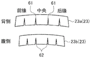
In the composite blade 10 according to embodiment 2, a plurality of slits 61 and 62 are formed in the metal patches 23a and 23 b. In the metal patch 23 shown in fig. 9, the upper side in fig. 9 is a metal patch 23a on the back side, and the lower side in fig. 9 is a metal patch 23b on the ventral side. The slit 61 of the metal patch 23a and the slit 62 of the metal patch 23b are slits cut from the blade root side. The slits 61, 62 are cut portions formed at predetermined intervals in the leaf width direction of the metal patch 23, and the slits 61, 62 are formed in a triangular shape having the root side as the bottom side and the apical side as the apex. The slits 61 and 62 are formed so as to extend in the leaf length direction, and have a length of 3/4 or less with respect to the entire length of the metal patch 23 in the leaf length direction. Therefore, the metal patches 23a and 23b are connected to each other at a portion in the leaf length direction where the slits 61 and 62 are formed. The width of the slit 62 of the metal patch 23b in the leaf width direction is wider than the slit 61 of the metal patch 23 a.
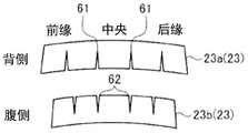
The slit 62 of the metal patch 23b may be as shown in fig. 10. That is, as shown in fig. 10, the blade root portion 21 on the ventral side has a shorter length in the blade width direction on the blade root side than on the blade tip side, and therefore the slit 62 of the metal patch 23b becomes a slit cut into the blade tip side.
As described above, according to embodiment 2, the slits 61 and 62 are formed in the metal patch 23, whereby the metal patch 23 can be allowed to expand or contract in the leaf width direction. Therefore, the metal patch 23 can absorb thermal elongation at the time of thermal curing of the root portion 21.
Claims (9)
1. A composite blade formed by laminating composite material layers containing reinforcing fibers and a resin, wherein,
the composite blade is provided with:
a blade root portion fitted to the blade groove;
a blade-shaped portion provided so as to extend from the blade root portion to a tip end side; and
a metal patch provided between the blade groove and the blade root portion and joined to the blade root portion,
the blade root portion is a laminate in which the composite material layers are laminated, and includes:
a leaf-shaped laminate body provided continuously from the leaf-shaped portion;
a blade root inner laminated body provided inside the blade-shaped laminated body; and
a blade root outer laminated body provided outside the blade-shaped laminated body,
the composite material layers of the lobed laminate being joined to one another in the lobed portion and separated by the root inner laminate in the root portion,
orienting the reinforcing fibers of the blade root inner laminate and the blade root outer laminate so that the linear expansion coefficient of the blade root approaches the linear expansion coefficient of the metal patch.
2. The composite blade of claim 1,
when the direction in which the blade-shaped portion extends is set to the 0 ° direction, the orientation ratio of the fiber direction of the reinforcing fibers in the blade-root inner laminate and the blade-root outer laminate is greater than 30% and less than 60% in the ± 45 ° direction.
3. The composite blade of claim 2,
in the blade root inner laminated body and the blade root outer laminated body, an orientation ratio of the reinforcing fibers in a direction of ± 45 ° is 35% or more and 55% or less.
4. The composite blade of claim 3,
in the blade root inner laminated body and the blade root outer laminated body, the orientation ratio of the reinforcing fibers in the fiber direction of 0 ° is 45% or more and 65% or less of the remaining orientation ratio in the fiber direction of ± 45 °.
5. The composite blade of claim 3,
in the blade-root inner laminate and the blade-root outer laminate, an orientation ratio of the reinforcing fibers in a fiber direction of ± 45 ° is 44% or more and 55% or less.
6. The composite blade of any one of claims 1 to 5,
a curved portion is formed between the root portion and the blade portion,
the metal patch is only arranged at the root of the leaf.
7. The composite blade of any one of claims 1 to 5,
the root portion has a groove formed for disposing the metal patch.
8. The composite blade of any one of claims 1 to 5,
in the installation surface of the blade root portion on which the metal patch is arranged, if a direction from the blade root portion side to the tip end side is a longitudinal direction and a direction orthogonal to the longitudinal direction is a width direction, the metal patch has a notch formed at a predetermined interval in the width direction.
9. A method of forming a composite blade formed by laminating composite material layers containing reinforcing fibers and a resin, wherein,
the composite blade is provided with:
a blade root portion fitted to the blade groove;
a blade-shaped portion provided so as to extend from the blade root portion to a tip end side; and
a metal patch disposed between the blade groove and the blade root and engaged with the blade root,
the blade root portion is a laminate in which the composite material layers are laminated, and includes:
a leaf-shaped laminate body provided continuously from the leaf-shaped portion;
a blade root inner laminated body provided inside the blade-shaped laminated body; and
a blade root outer laminated body provided outside the blade-shaped laminated body,
the composite material layers of the lobed laminate being joined to one another in the lobed portion and separated by the root inner laminate in the root portion,
the forming method comprises the following steps:
a placement step of placing the metal patch in a forming die for forming the root portion of the blade;
a lamination step of laminating the composite material layer on the metal patches to form the blade-shaped laminate, the blade-root-inner laminate, and the blade-root-outer laminate; and
a curing step of heating and curing the blade-shaped laminate, the blade-root-inner laminate, and the blade-root-outer laminate,
in the lamination step, the reinforcing fibers of the blade-root inner laminate and the blade-root outer laminate are oriented so that the linear expansion coefficient of the blade root portion approaches the linear expansion coefficient of the metal patch.
Applications Claiming Priority (2)
| Application Number | Priority Date | Filing Date | Title |
|---|---|---|---|
| JP2019113879A JP7236337B2 (en) | 2019-06-19 | 2019-06-19 | Composite material wing and molding method for composite material wing |
| JP2019-113879 | 2019-06-19 |
Publications (2)
| Publication Number | Publication Date |
|---|---|
| CN112109341A CN112109341A (en) | 2020-12-22 |
| CN112109341B true CN112109341B (en) | 2022-06-21 |
Family
ID=69570579
Family Applications (1)
| Application Number | Title | Priority Date | Filing Date |
|---|---|---|---|
| CN202010097748.3A Active CN112109341B (en) | 2019-06-19 | 2020-02-17 | Composite blade and method for forming composite blade |
Country Status (4)
| Country | Link |
|---|---|
| US (1) | US11384647B2 (en) |
| EP (1) | EP3754159B1 (en) |
| JP (1) | JP7236337B2 (en) |
| CN (1) | CN112109341B (en) |
Families Citing this family (2)
| Publication number | Priority date | Publication date | Assignee | Title |
|---|---|---|---|---|
| FR3081944B1 (en) * | 2018-05-31 | 2020-06-19 | Safran Electrical & Power | AIR COMPRESSOR THERMAL ARCHITECTURE |
| CN114294263B (en) * | 2021-10-20 | 2023-06-30 | 中国航发四川燃气涡轮研究院 | Fan blade disc structure and turbofan engine |
Citations (7)
| Publication number | Priority date | Publication date | Assignee | Title |
|---|---|---|---|---|
| US5804756A (en) * | 1995-12-18 | 1998-09-08 | Rjc Development, L.C. | Composite/metallic gun barrel having matched coefficients of thermal expansion |
| US6290466B1 (en) * | 1999-09-17 | 2001-09-18 | General Electric Company | Composite blade root attachment |
| CN102770623A (en) * | 2009-11-17 | 2012-11-07 | 西门子公司 | Turbine or compressor blade |
| CN103291370A (en) * | 2012-02-22 | 2013-09-11 | 通用电气公司 | Interlaminar stress reducing configuration for composite turbine components |
| CN105264176A (en) * | 2013-03-08 | 2016-01-20 | 通用电气公司 | Turbine assembly and system for preventing leakage, corresponding methods of assembling and preventing air leakage |
| JP2016527426A (en) * | 2013-05-29 | 2016-09-08 | ゼネラル・エレクトリック・カンパニイ | Composite airfoil metal patch |
| JP2018204461A (en) * | 2017-05-31 | 2018-12-27 | 三菱重工業株式会社 | Composite material blade and manufacturing method of composite material blade |
Family Cites Families (10)
| Publication number | Priority date | Publication date | Assignee | Title |
|---|---|---|---|---|
| JPS5522639B2 (en) * | 1972-10-20 | 1980-06-18 | ||
| US4040770A (en) * | 1975-12-22 | 1977-08-09 | General Electric Company | Transition reinforcement of composite blade dovetails |
| DE102006049818A1 (en) * | 2006-10-18 | 2008-04-24 | Rolls-Royce Deutschland Ltd & Co Kg | Fan blade made of textile composite material |
| JP4865507B2 (en) | 2006-11-01 | 2012-02-01 | 株式会社日立ソリューションズ | Management authority setting system |
| JP4990181B2 (en) * | 2007-07-06 | 2012-08-01 | 三菱電機株式会社 | Advanced grid structure |
| US8794925B2 (en) * | 2010-08-24 | 2014-08-05 | United Technologies Corporation | Root region of a blade for a gas turbine engine |
| GB201106050D0 (en) * | 2011-04-11 | 2011-05-25 | Rolls Royce Plc | A retention device for a composite blade of a gas turbine engine |
| US10487670B2 (en) * | 2013-03-13 | 2019-11-26 | Rolls-Royce Corporation | Gas turbine engine component including a compliant layer |
| WO2015057369A1 (en) * | 2013-10-14 | 2015-04-23 | United Technologies Corporation | Blade wedge attachment lay-up |
| JP6765344B2 (en) * | 2017-05-31 | 2020-10-07 | 三菱重工業株式会社 | Method for manufacturing composite blades and composite blades |
-
2019
- 2019-06-19 JP JP2019113879A patent/JP7236337B2/en active Active
-
2020
- 2020-02-10 EP EP20156467.1A patent/EP3754159B1/en active Active
- 2020-02-14 US US16/790,903 patent/US11384647B2/en active Active
- 2020-02-17 CN CN202010097748.3A patent/CN112109341B/en active Active
Patent Citations (7)
| Publication number | Priority date | Publication date | Assignee | Title |
|---|---|---|---|---|
| US5804756A (en) * | 1995-12-18 | 1998-09-08 | Rjc Development, L.C. | Composite/metallic gun barrel having matched coefficients of thermal expansion |
| US6290466B1 (en) * | 1999-09-17 | 2001-09-18 | General Electric Company | Composite blade root attachment |
| CN102770623A (en) * | 2009-11-17 | 2012-11-07 | 西门子公司 | Turbine or compressor blade |
| CN103291370A (en) * | 2012-02-22 | 2013-09-11 | 通用电气公司 | Interlaminar stress reducing configuration for composite turbine components |
| CN105264176A (en) * | 2013-03-08 | 2016-01-20 | 通用电气公司 | Turbine assembly and system for preventing leakage, corresponding methods of assembling and preventing air leakage |
| JP2016527426A (en) * | 2013-05-29 | 2016-09-08 | ゼネラル・エレクトリック・カンパニイ | Composite airfoil metal patch |
| JP2018204461A (en) * | 2017-05-31 | 2018-12-27 | 三菱重工業株式会社 | Composite material blade and manufacturing method of composite material blade |
Non-Patent Citations (1)
| Title |
|---|
| Evaluation of thermal expansion coefficient of carbon fiber reinforced composites using electronic speckle interferometry;Chengzhi Dong;《OPTICS EXPRESS》;20180108;531-543 * |
Also Published As
| Publication number | Publication date |
|---|---|
| JP2021001549A (en) | 2021-01-07 |
| EP3754159B1 (en) | 2023-01-04 |
| EP3754159A8 (en) | 2021-02-24 |
| US11384647B2 (en) | 2022-07-12 |
| JP7236337B2 (en) | 2023-03-09 |
| EP3754159A1 (en) | 2020-12-23 |
| CN112109341A (en) | 2020-12-22 |
| US20200400027A1 (en) | 2020-12-24 |
Similar Documents
| Publication | Publication Date | Title |
|---|---|---|
| US11208904B2 (en) | Method for manufacturing a vane from a composite material with a fitted metal leading edge for a gas turbine | |
| US20140271217A1 (en) | Efficient wind turbine blade design and associated manufacturing methods using rectangular spars and segmented shear web | |
| US10066491B2 (en) | Fibre composite component for the rotor blade of a wind turbine | |
| EP2781344B1 (en) | Method of manufacturing a portion of a wind turbine blade | |
| EP2211018B1 (en) | Airfoil | |
| CN112109341B (en) | Composite blade and method for forming composite blade | |
| EP2971756B1 (en) | Wind turbine blades with layered, multi-component spars, and associated systems | |
| JP6778147B2 (en) | Method for manufacturing composite blades and composite blades | |
| CN110709583B (en) | Composite blade and method for manufacturing composite blade | |
| CN111823611B (en) | Composite blade and method for forming composite blade | |
| US11680489B2 (en) | Method for manufacturing a composite guide vane having a metallic leading edge | |
| US11679536B2 (en) | Method for molding composite material blade, composite material blade, and molding die for composite material blade | |
| US10906267B2 (en) | Composite structure | |
| US11371365B2 (en) | Composite blade and method for manufacturing composite blade | |
| WO2021187016A1 (en) | Composite material blade, rotating machine, and method for molding composite material blade | |
| US11780179B2 (en) | Thermoplastic composite panel with corrugated peaks and troughs stiffening systems and methods |
Legal Events
| Date | Code | Title | Description |
|---|---|---|---|
| PB01 | Publication | ||
| PB01 | Publication | ||
| SE01 | Entry into force of request for substantive examination | ||
| SE01 | Entry into force of request for substantive examination | ||
| GR01 | Patent grant | ||
| GR01 | Patent grant |