CN112080963A - High-toughness dry and wet toilet paper and processing technology thereof - Google Patents
High-toughness dry and wet toilet paper and processing technology thereof Download PDFInfo
- Publication number
- CN112080963A CN112080963A CN202010942125.1A CN202010942125A CN112080963A CN 112080963 A CN112080963 A CN 112080963A CN 202010942125 A CN202010942125 A CN 202010942125A CN 112080963 A CN112080963 A CN 112080963A
- Authority
- CN
- China
- Prior art keywords
- grinding disc
- gear
- motor
- driven
- driving
- Prior art date
- Legal status (The legal status is an assumption and is not a legal conclusion. Google has not performed a legal analysis and makes no representation as to the accuracy of the status listed.)
- Withdrawn
Links
Images


Classifications
-
- D—TEXTILES; PAPER
- D21—PAPER-MAKING; PRODUCTION OF CELLULOSE
- D21H—PULP COMPOSITIONS; PREPARATION THEREOF NOT COVERED BY SUBCLASSES D21C OR D21D; IMPREGNATING OR COATING OF PAPER; TREATMENT OF FINISHED PAPER NOT COVERED BY CLASS B31 OR SUBCLASS D21G; PAPER NOT OTHERWISE PROVIDED FOR
- D21H27/00—Special paper not otherwise provided for, e.g. made by multi-step processes
- D21H27/002—Tissue paper; Absorbent paper
-
- A—HUMAN NECESSITIES
- A01—AGRICULTURE; FORESTRY; ANIMAL HUSBANDRY; HUNTING; TRAPPING; FISHING
- A01F—PROCESSING OF HARVESTED PRODUCE; HAY OR STRAW PRESSES; DEVICES FOR STORING AGRICULTURAL OR HORTICULTURAL PRODUCE
- A01F29/00—Cutting apparatus specially adapted for cutting hay, straw or the like
- A01F29/005—Cutting apparatus specially adapted for cutting hay, straw or the like for disintegrating and cutting up bales of hay, straw or fodder
-
- A—HUMAN NECESSITIES
- A01—AGRICULTURE; FORESTRY; ANIMAL HUSBANDRY; HUNTING; TRAPPING; FISHING
- A01F—PROCESSING OF HARVESTED PRODUCE; HAY OR STRAW PRESSES; DEVICES FOR STORING AGRICULTURAL OR HORTICULTURAL PRODUCE
- A01F29/00—Cutting apparatus specially adapted for cutting hay, straw or the like
- A01F29/02—Cutting apparatus specially adapted for cutting hay, straw or the like having rotating knives with their cutting edges in a plane perpendicular to their rotational axis
- A01F29/04—Cutting apparatus specially adapted for cutting hay, straw or the like having rotating knives with their cutting edges in a plane perpendicular to their rotational axis with feeding direction transverse to axis
-
- A—HUMAN NECESSITIES
- A01—AGRICULTURE; FORESTRY; ANIMAL HUSBANDRY; HUNTING; TRAPPING; FISHING
- A01F—PROCESSING OF HARVESTED PRODUCE; HAY OR STRAW PRESSES; DEVICES FOR STORING AGRICULTURAL OR HORTICULTURAL PRODUCE
- A01F29/00—Cutting apparatus specially adapted for cutting hay, straw or the like
- A01F29/09—Details
-
- A—HUMAN NECESSITIES
- A47—FURNITURE; DOMESTIC ARTICLES OR APPLIANCES; COFFEE MILLS; SPICE MILLS; SUCTION CLEANERS IN GENERAL
- A47K—SANITARY EQUIPMENT NOT OTHERWISE PROVIDED FOR; TOILET ACCESSORIES
- A47K10/00—Body-drying implements; Toilet paper; Holders therefor
- A47K10/16—Paper towels; Toilet paper; Holders therefor
-
- B—PERFORMING OPERATIONS; TRANSPORTING
- B02—CRUSHING, PULVERISING, OR DISINTEGRATING; PREPARATORY TREATMENT OF GRAIN FOR MILLING
- B02C—CRUSHING, PULVERISING, OR DISINTEGRATING IN GENERAL; MILLING GRAIN
- B02C23/00—Auxiliary methods or auxiliary devices or accessories specially adapted for crushing or disintegrating not provided for in preceding groups or not specially adapted to apparatus covered by a single preceding group
- B02C23/08—Separating or sorting of material, associated with crushing or disintegrating
- B02C23/10—Separating or sorting of material, associated with crushing or disintegrating with separator arranged in discharge path of crushing or disintegrating zone
-
- B—PERFORMING OPERATIONS; TRANSPORTING
- B07—SEPARATING SOLIDS FROM SOLIDS; SORTING
- B07B—SEPARATING SOLIDS FROM SOLIDS BY SIEVING, SCREENING, SIFTING OR BY USING GAS CURRENTS; SEPARATING BY OTHER DRY METHODS APPLICABLE TO BULK MATERIAL, e.g. LOOSE ARTICLES FIT TO BE HANDLED LIKE BULK MATERIAL
- B07B1/00—Sieving, screening, sifting, or sorting solid materials using networks, gratings, grids, or the like
- B07B1/28—Moving screens not otherwise provided for, e.g. swinging, reciprocating, rocking, tilting or wobbling screens
-
- B—PERFORMING OPERATIONS; TRANSPORTING
- B07—SEPARATING SOLIDS FROM SOLIDS; SORTING
- B07B—SEPARATING SOLIDS FROM SOLIDS BY SIEVING, SCREENING, SIFTING OR BY USING GAS CURRENTS; SEPARATING BY OTHER DRY METHODS APPLICABLE TO BULK MATERIAL, e.g. LOOSE ARTICLES FIT TO BE HANDLED LIKE BULK MATERIAL
- B07B1/00—Sieving, screening, sifting, or sorting solid materials using networks, gratings, grids, or the like
- B07B1/42—Drive mechanisms, regulating or controlling devices, or balancing devices, specially adapted for screens
-
- D—TEXTILES; PAPER
- D21—PAPER-MAKING; PRODUCTION OF CELLULOSE
- D21B—FIBROUS RAW MATERIALS OR THEIR MECHANICAL TREATMENT
- D21B1/00—Fibrous raw materials or their mechanical treatment
- D21B1/04—Fibrous raw materials or their mechanical treatment by dividing raw materials into small particles, e.g. fibres
- D21B1/12—Fibrous raw materials or their mechanical treatment by dividing raw materials into small particles, e.g. fibres by wet methods, by the use of steam
- D21B1/14—Disintegrating in mills
- D21B1/26—Driving or feeding arrangements
-
- D—TEXTILES; PAPER
- D21—PAPER-MAKING; PRODUCTION OF CELLULOSE
- D21C—PRODUCTION OF CELLULOSE BY REMOVING NON-CELLULOSE SUBSTANCES FROM CELLULOSE-CONTAINING MATERIALS; REGENERATION OF PULPING LIQUORS; APPARATUS THEREFOR
- D21C9/00—After-treatment of cellulose pulp, e.g. of wood pulp, or cotton linters ; Treatment of dilute or dewatered pulp or process improvement taking place after obtaining the raw cellulosic material and not provided for elsewhere
- D21C9/10—Bleaching ; Apparatus therefor
- D21C9/1068—Bleaching ; Apparatus therefor with O2
-
- D—TEXTILES; PAPER
- D21—PAPER-MAKING; PRODUCTION OF CELLULOSE
- D21H—PULP COMPOSITIONS; PREPARATION THEREOF NOT COVERED BY SUBCLASSES D21C OR D21D; IMPREGNATING OR COATING OF PAPER; TREATMENT OF FINISHED PAPER NOT COVERED BY CLASS B31 OR SUBCLASS D21G; PAPER NOT OTHERWISE PROVIDED FOR
- D21H11/00—Pulp or paper, comprising cellulose or lignocellulose fibres of natural origin only
- D21H11/12—Pulp from non-woody plants or crops, e.g. cotton, flax, straw, bagasse
-
- D—TEXTILES; PAPER
- D21—PAPER-MAKING; PRODUCTION OF CELLULOSE
- D21H—PULP COMPOSITIONS; PREPARATION THEREOF NOT COVERED BY SUBCLASSES D21C OR D21D; IMPREGNATING OR COATING OF PAPER; TREATMENT OF FINISHED PAPER NOT COVERED BY CLASS B31 OR SUBCLASS D21G; PAPER NOT OTHERWISE PROVIDED FOR
- D21H17/00—Non-fibrous material added to the pulp, characterised by its constitution; Paper-impregnating material characterised by its constitution
- D21H17/20—Macromolecular organic compounds
- D21H17/21—Macromolecular organic compounds of natural origin; Derivatives thereof
- D21H17/24—Polysaccharides
-
- D—TEXTILES; PAPER
- D21—PAPER-MAKING; PRODUCTION OF CELLULOSE
- D21H—PULP COMPOSITIONS; PREPARATION THEREOF NOT COVERED BY SUBCLASSES D21C OR D21D; IMPREGNATING OR COATING OF PAPER; TREATMENT OF FINISHED PAPER NOT COVERED BY CLASS B31 OR SUBCLASS D21G; PAPER NOT OTHERWISE PROVIDED FOR
- D21H17/00—Non-fibrous material added to the pulp, characterised by its constitution; Paper-impregnating material characterised by its constitution
- D21H17/63—Inorganic compounds
- D21H17/67—Water-insoluble compounds, e.g. fillers, pigments
- D21H17/675—Oxides, hydroxides or carbonates
-
- D—TEXTILES; PAPER
- D21—PAPER-MAKING; PRODUCTION OF CELLULOSE
- D21H—PULP COMPOSITIONS; PREPARATION THEREOF NOT COVERED BY SUBCLASSES D21C OR D21D; IMPREGNATING OR COATING OF PAPER; TREATMENT OF FINISHED PAPER NOT COVERED BY CLASS B31 OR SUBCLASS D21G; PAPER NOT OTHERWISE PROVIDED FOR
- D21H21/00—Non-fibrous material added to the pulp, characterised by its function, form or properties; Paper-impregnating or coating material, characterised by its function, form or properties
- D21H21/06—Paper forming aids
- D21H21/08—Dispersing agents for fibres
-
- D—TEXTILES; PAPER
- D21—PAPER-MAKING; PRODUCTION OF CELLULOSE
- D21H—PULP COMPOSITIONS; PREPARATION THEREOF NOT COVERED BY SUBCLASSES D21C OR D21D; IMPREGNATING OR COATING OF PAPER; TREATMENT OF FINISHED PAPER NOT COVERED BY CLASS B31 OR SUBCLASS D21G; PAPER NOT OTHERWISE PROVIDED FOR
- D21H21/00—Non-fibrous material added to the pulp, characterised by its function, form or properties; Paper-impregnating or coating material, characterised by its function, form or properties
- D21H21/14—Non-fibrous material added to the pulp, characterised by its function, form or properties; Paper-impregnating or coating material, characterised by its function, form or properties characterised by function or properties in or on the paper
- D21H21/18—Reinforcing agents
- D21H21/20—Wet strength agents
Abstract
The invention discloses high-toughness dry and wet toilet paper and a processing technology thereof, wherein the high-toughness dry and wet toilet paper comprises the following raw materials in parts by weight: 40-50 parts of straws, 15-20 parts of wood fibers and 5-10 parts of cotton fibers, the straws are put into a crushing and screening machine for processing, the screen divides straw scraps into long straw fibers and straw powder, the straw powder is put into a pulping machine for processing, the long straw fibers are added into the pulping machine, meanwhile, the wood fibers and the cotton fibers are added, a third motor drives a stirring wheel to heat, stir and mix long fiber pulp, fine powder pulp and liquid medicine A, the third motor drives the stirring wheel to stir pulp material A and liquid medicine B, and after uniform stirring, strengthened paper pulp is obtained, so that the paper pulp yield is improved, the bulk and the wet strength of the toilet paper are improved, the prepared toilet paper has good softness and good water absorption, and simultaneously, the color of the paper can be uniform.
Description
Technical Field
The invention relates to the technical field of papermaking, in particular to high-toughness dry and wet toilet paper and a processing technology thereof.
Background
At present, toilet paper is one of daily paper indispensable in daily life of people, and has the main advantages of convenient and comfortable use, no repeated use, safety and sanitation.
The toilet paper is developed rapidly, the raw material of the toilet paper is mainly wood pulp, the toilet paper is formed by interweaving fibers, the structure of the toilet paper is loose and porous, and the toilet paper has good air permeability. With the improvement of living standard and the enhancement of health consciousness of people, people put forward new requirements on partial daily paper, and the current requirement products not only have high hygroscopicity, but also have good mechanical properties and are not easy to break when meeting water.
Disclosure of Invention
The invention aims to provide high-toughness dry and wet toilet paper and a processing technology thereof, and aims to solve the problems of how to improve the toughness and the moisture absorption of the toilet paper, improve the quality and the strength of the toilet paper, reduce the environmental pollution in the production process and avoid the rupture of the toilet paper when meeting water.
The purpose of the invention can be realized by the following technical scheme:
a high-toughness dry and wet dual-purpose toilet paper comprises the following raw materials in parts by weight: 40-50 parts of straw, 15-20 parts of wood fiber and 5-10 parts of cotton fiber.
A processing technology of high-toughness wet and dry toilet paper comprises the following production steps:
the method comprises the following steps: selecting raw materials, screening the raw materials according to the types of the raw materials, selecting high-quality raw materials, weighing according to the weight ratio, respectively putting 40-50 parts of straws, 15-20 parts of wood fibers and 5-10 parts of cotton into clear water for soaking and cleaning, filtering impurities after cleaning, fishing out, and drying for later use;
step two: putting the straws prepared in the step one into a crushing and screening machine for processing, driving a first driven gear and a second driven gear by a first motor through driving a driving gear, driving the driving gear, the first driven gear and the second driven gear respectively driving a main rotating rod, a first driven rod and a second driven rod which are respectively connected with the driving gear, the first driven gear and the second driven gear to rotate so as to drive a cutting blade to rotate, crushing the straws into straw scraps, enabling the straw scraps to fall into a screening box body, connecting a discharge port of the crushing box body with a feed port of the screening box body through a telescopic cover, driving the screening box body to vibrate by a vibrator, connecting the screening box body with a device frame through a vibrating spring and a connecting rod, driving the spring to contract and stretch under the vibration of the vibrator, improving the vibration frequency of the screening box body, improving the screening efficiency of a screen in the screening box body on the straw scraps, and dividing the straw, the powder passing through the screen falls onto the conveyor through the material receiving port, the long straw fibers which do not pass through the screen fall into the material receiving box through the connecting pipe, and the long straw fibers are gathered for later use through the material receiving box;
step three: putting the straw powder prepared in the second step into a pulping machine by a conveyor for processing, adding clear water into a pulping box body, driving a first gear and a second grinding disc to rotate by a second motor, driving the second gear to rotate by the first gear, driving the first grinding disc to rotate by the second gear, impacting and extruding the straw powder slurry falling between the first grinding disc and the second grinding disc through the relative motion between the first grinding disc and the second grinding disc, gradually grinding the straw powder slurry into fine powder slurry, enabling the fine powder slurry to fall into the bottom of the pulping box body along with a percolation seam on the second grinding disc, and conveying the fine powder slurry into a heating stirrer through a pump and a pipeline connected with a discharge valve;
step four: adding clean water into the pulping machine in the fourth step for washing, adding the long straw fibers obtained in the second step into the pulping machine after all the fine powder pulp in the fourth step is discharged out of the pulping machine, mixing the long straw fibers with the clean water, simultaneously adding prepared wood fibers and cotton fibers, driving a first gear and a second grinding disc to rotate by a second motor, driving a second gear to rotate by the first gear, driving a first grinding disc to rotate by the second gear, impacting and extruding the mixed fiber pulp falling between the first grinding disc and the second grinding disc through the relative motion between the first grinding disc and the second grinding disc, gradually grinding the mixed fiber pulp into long fiber pulp, and conveying the long fiber pulp into a heating stirrer through a pump and a pipeline which are connected with a discharge valve, wherein the long fiber pulp falls into the bottom of a pulping box along with a percolation seam on the second grinding disc;
step five: adding the liquid medicine A into a heating stirrer, sealing a heating stirring box, driving a stirring wheel by a third motor to heat, stir and mix long fiber slurry, fine powder slurry and the liquid medicine A to obtain mixed slurry, and then performing oxygen delignification treatment on the mixed slurry to obtain slurry A;
step six: adding the liquid medicine B into the pulp A, sealing the heating stirring box, driving a stirring wheel by a third motor to stir the pulp A and the liquid medicine B, and uniformly stirring to obtain reinforced paper pulp;
step seven: and (4) squeezing and sucking the reinforced paper pulp obtained in the step six in a paper sheet forming machine to form paper sheets, and then drying, reeling, cutting and packaging the formed paper sheets to finally obtain finished toilet paper.
As a further scheme of the invention, the crushing and screening machine comprises a device frame, a crushing box, a dust cover, a first motor, a main rotating rod, a first driven rod, a second driven rod, a driving gear, a first driven gear, a second driven gear, a cutting blade, a feeding hopper, a support bearing, a telescopic cover, a screening box body, a screen, a connecting pipe, a material receiving box, a vibrator, a mounting frame and a material receiving port, wherein the crushing box is fixedly arranged at the upper end of the device frame, the feeding hopper is fixedly connected at the center of the upper end of the crushing box, the main rotating rod, the first driven rod and the second driven rod are arranged in a row in the vertical direction, the main rotating rod is positioned between the first driven rod and the second driven rod, and the support bearings are arranged on the same side of the main rotating rod, the first driven rod, the supporting bearing penetrates through the box wall of the crushing box, the outer ring of the supporting bearing is fixedly connected with the crushing box, the other sides of the main rotating rod, the first driven rod and the second driven rod penetrate through the box wall of the crushing box and are rotatably connected with the crushing box, the end part of the main rotating rod is fixedly connected with the driving shaft of the first motor, the end part of the main rotating rod is fixedly connected with the inner ring of the driving gear, the first driven rod is fixedly connected with the inner ring of the first driven gear, the second driven rod is fixedly connected with the inner ring of the second driven gear, the driving gear is respectively meshed with the first driven gear and the second driven gear, the cutting blades are arranged on the main rotating rod, the first driven rod and the second driven rod, the first motor is arranged in the dust cover, the driving shaft of the first motor penetrates through the dust cover and is rotatably connected with the dust cover, and the end part of the driving shaft of the first motor is fixedly connected with the inner ring of the driving gear and;
screening box fixed mounting is in the device frame, the screening box is located smashes the case under, the feed inlet of screening box is linked together through flexible cover with the discharge gate of smashing the case, the slope of screening box sets up, fixed mounting has the screen cloth in the screening box, the fixed mounting bracket that is provided with of screening box lower extreme, install a plurality of groups vibrator on the mounting bracket.
As a further scheme of the invention, four groups of upper connecting frames are arranged at the lower end of the device rack, four groups of lower connecting frames corresponding to the upper connecting frames are arranged at the upper end of the screening box body, connecting rods are mounted at the upper ends of the lower connecting frames, connecting sleeves are connected at the upper ends of the connecting rods, connecting hooks are arranged at the upper ends of the connecting sleeves, the connecting hooks are connected with the upper connecting frames, the vibration springs are sleeved on the peripheries of the connecting rods, the lower ends of the vibration springs are connected with the lower connecting frames, and the upper ends of the vibration springs are connected on the connecting sleeves.
As a further scheme of the invention, the pulping machine comprises a second motor, a motor cover, a first gear, a second gear, a first grinding disc, a second grinding disc, a pulping box body, a water inlet valve and a discharge valve, wherein the water inlet valve is installed at the edge of the top of the pulping box body, a through hole is formed in the center of the top of the pulping box body and is rotationally connected with a rotating shaft of the first grinding disc, the rotating shaft of the second grinding disc penetrates through the rotating shaft of the first grinding disc and is rotationally connected with the rotating shaft of the first grinding disc, the second grinding disc is slidably connected with the first grinding disc, the end part of the rotating shaft of the second grinding disc is fixedly connected with the end part of a driving shaft of the second motor, teeth marks are carved on the periphery of the driving shaft of the second motor and are in meshed connection with the first gear, the first gear is in meshed connection with the second gear, teeth marks are carved on the periphery of the end part of the, the first gear and the second gear are installed at the top of the pulping box body and are rotationally connected with the pulping box body, the second motor, the first gear and the second gear are covered with the motor cover, and the second motor is fixedly connected with the top of the motor cover.
As a further scheme of the invention, the first grinding disc comprises an upper fixing ring, an upper grinding disc main body and connecting rods, the end part of a rotating shaft of the first grinding disc is fixedly connected with the upper grinding disc main body through a plurality of connecting rods, the upper grinding disc main body is annular, the upper surface of the upper grinding disc main body is a smooth surface, the lower surface of the upper grinding disc main body is provided with a plurality of S-shaped grinding strips, the upper fixing ring is sleeved on the edge of the upper grinding disc main body, the second grinding disc comprises a lower fixing ring and a lower grinding disc main body, the upper surface of the lower grinding disc main body is provided with a plurality of curved grinding strips, a plurality of percolation seams are uniformly distributed near the edge of the lower grinding disc main body.
As a further scheme of the invention, the heating stirrer comprises a heating stirring box, a heater, a third motor, a first feeding valve, a second feeding valve, a stirring wheel and a slurry outlet valve, wherein the third motor is installed in the center of the top of the heating stirring box, a driving shaft of the third motor penetrates through the top of the heating stirring box and is rotatably connected with the heating stirring box, the end part of the driving shaft of the third motor is fixedly connected with the end part of a rotating shaft of the stirring wheel, a plurality of stirring rings are uniformly distributed on the rotating shaft of the stirring wheel, the first feeding valve and the second feeding valve are installed on the top of the heating stirring box and are positioned on two sides of the third motor, one side of the bottom of the heating stirring box is provided with a through hole and is provided with the slurry outlet valve, and the center of the bottom of the heating stirring box.
As a further proposal of the invention, the liquid medicine A is a mixed liquid medicine consisting of sodium hydroxide, sodium sulfite, sodium borohydride, alkyl polyglucoside and water, and the liquid medicine B is a wet strength agent with the concentration of 0.2 to 0.5 percent and a papermaking dispersant with the concentration of 0.05 to 0.07 percent.
The invention has the beneficial effects that: the first motor drives the driving gear, thereby driving the first driven gear and the second driven gear, the driving gear, the first driven gear and the second driven gear respectively drive the main rotating rod which is respectively connected, the first driven rod and the second driven rod rotate, thereby driving the cutting blade to rotate, the main rotating rod and the two groups of driven rods are driven to rotate by one group of first motor, the cost is effectively reduced by the arrangement of the driving motor, the straws are put into the crushing and screening machine for processing, the straws are crushed into straw scraps, the straw scraps fall into the screening box body, the discharge port of the crushing box is connected with the feed port of the screening box body by the telescopic cover, the powder is effectively prevented from floating when falling, the environment is prevented from being polluted, meanwhile, other sundries are effectively prevented from polluting the straw powder, the vibrator drives the screening box body to vibrate, the screening box body is connected with the device frame by the vibration spring and the connecting rod, under the vibration of the vibrator, the spring is driven to contract and stretch, the vibration frequency of the screening box body is effectively improved, the screening effect of a screen cloth in the screening box body on powder is improved, the second motor drives the first gear and the second grinding disc to rotate, the first gear drives the second gear to rotate, the second gear drives the first grinding disc to rotate, the first grinding disc and the second grinding disc can rotate and grind in opposite directions, the grinding efficiency is improved, the first grinding disc and the second grinding disc are buckled through the sliding connection of the upper fixing ring and the lower fixing ring, the upper surface of the upper grinding disc main body is an inverted conical curved surface, the falling slurry can be guided into the rotating shaft, the grinding surfaces of the first grinding disc and the second grinding disc are provided with grinding strips, the grinding quality can be greatly improved, and the straw powder slurry falling between the first grinding disc and the second grinding disc is impacted and extruded through the relative motion between the first grinding disc and the second grinding disc, the method has the advantages that the yield of paper pulp can be improved, the wet strength agent and the papermaking dispersing agent are added into the washed pulp, the bulk and the wet strength of the toilet paper are improved, the prepared toilet paper has good softness and good water absorption, and meanwhile, the color of the paper can be uniform.
Drawings
In order to facilitate understanding for those skilled in the art, the present invention will be further described with reference to the accompanying drawings.
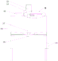
FIG. 1 is a schematic view of the overall structure of the present invention;
FIG. 2 is a schematic diagram of a size reduction screen according to the present invention;
FIG. 3 is a side view of a pulverizing and screening machine of the present invention;
FIG. 4 is an enlarged schematic view of circle A in FIG. 2;
FIG. 5 is a schematic view of a refiner of the present invention;
FIG. 6 is an enlarged schematic view of circle B in FIG. 5;
FIG. 7 is a top plan view of the refiner of the present invention with the motor cover and second motor removed;
FIG. 8 is a schematic view of the abrasive surface of a first abrasive disc of the present invention;
FIG. 9 is a schematic illustration of the abrasive surface of a second abrasive disc of the present invention;
FIG. 10 is a schematic view of a heated blender in accordance with the present invention;
in the figure: 1. a crushing and screening machine; 2. a conveyor; 3. pulping machine; 4. a pump machine; 5. a pipeline; 6. heating the stirrer; 7. a device frame; 8. a crushing box; 9. a dust cover; 10. a first motor; 11. a main rotating rod; 12. a first driven lever; 13. a driving gear; 14. a first driven gear; 15. a second driven gear; 16. cutting the blade; 17. a feed hopper; 18. a support bearing; 19. a telescopic cover; 20. screening the box body; 21. screening a screen; 22. a connecting pipe; 23. a material receiving box; 24. an upper connecting frame; 25. connecting a hook; 26. vibrating the spring; 27. connecting sleeves; 28. a connecting rod; 29. a lower connecting frame; 30. a vibrator; 31. a mounting frame; 32. a material receiving port; 33. a second motor; 34. a motor cover; 35. a first gear; 36. a second gear; 37. a first abrasive disc; 38. a second grinding disc; 39. a pulping box body; 40. a water inlet valve; 41. a discharge valve; 42. heating the stirring box; 43. a heater; 44. a third motor; 45. a first feed valve; 46. a second feed valve; 47. a stirring wheel; 48. a slurry outlet valve; 49. a second driven lever; 371. an upper fixing ring; 372. an upper millstone body; 373. connecting a rod; 381. a lower fixing ring; 382. the lower grinding disc main body.
Detailed Description
The technical solutions of the present invention will be described clearly and completely with reference to the following embodiments, and it should be understood that the described embodiments are only a part of the embodiments of the present invention, and not all of the embodiments. All other embodiments, which can be derived by a person skilled in the art from the embodiments given herein without making any creative effort, shall fall within the protection scope of the present invention.
Example 1
Referring to fig. 1-10, a high-toughness wet and dry toilet paper comprises the following raw materials in parts by weight: 40 parts of straw, 20 parts of wood fiber and 10 parts of cotton fiber.
A processing technology of high-toughness wet and dry toilet paper comprises the following production steps:
the method comprises the following steps: selecting raw materials, screening the raw materials according to the types of the raw materials, selecting high-quality raw materials, weighing according to the weight ratio, respectively putting 40 parts of straws, 20 parts of wood fibers and 10 parts of cotton into clean water for soaking and cleaning, filtering impurities after cleaning, fishing out, and drying for later use;
step two: putting the straws prepared in the step one into a crushing and screening machine 1 for processing, driving a driving gear 13 by a first motor 10 to drive a first driven gear 14 and a second driven gear 15, respectively driving a main rotating rod 11, a first driven rod 12 and a second driven rod 49 which are respectively connected by the driving gear 13, the first driven gear 14 and the second driven gear 15 to rotate so as to drive a cutting blade 16 to rotate, crushing the straws into straw scraps, enabling the straw scraps to fall into a screening box body 20, connecting a discharge port of the crushing box 8 with a feed port of the screening box body 20 through a telescopic cover 19, driving the screening box body 20 to vibrate by a vibrator 30, connecting the screening box body 20 with a device frame 7 through a vibration spring 26 and a connecting rod 28, driving the spring to contract and stretch under the vibration of the vibrator 30, improving the vibration frequency of the screening box body 20, and improving the screening efficiency of a screen 21 in the screening box body 20 on the straw scraps, the screen 21 divides the straw scraps into long straw fibers and straw powder, the powder passing through the screen 21 falls onto the conveyor 2 through the material receiving port 32, the long straw fibers not passing through the screen 21 fall into the material receiving box 23 through the connecting pipe 22, and the long straw fibers are gathered for later use through the material receiving box 23;
step three: putting the straw powder prepared in the second step into a pulping machine 3 by a conveyor 2 for processing, adding clear water into a pulping box 39, driving a first gear 35 and a second grinding disc 38 to rotate by a second motor 33, driving a second gear 36 to rotate by the first gear 35, driving a first grinding disc 37 to rotate by the second gear 36, impacting and extruding the straw powder slurry falling between the first grinding disc 37 and the second grinding disc 38 through the relative motion between the first grinding disc 37 and the second grinding disc 38, gradually grinding the straw powder slurry into fine powder slurry, enabling the fine powder slurry to fall into the bottom of the pulping box 39 along with a percolation seam on the second grinding disc 38, and conveying the fine powder slurry into a heating stirrer 6 through a pump 4 and a pipeline 5 which are connected with a discharge valve 41;
step four: adding clean water into the pulping machine 3 in the fourth step for washing, adding the long straw fibers obtained in the second step into the pulping machine 3 after all the fine powder pulp in the fourth step is discharged out of the pulping machine 3, mixing the long straw fibers with the clean water, simultaneously adding prepared wood fibers and cotton fibers, driving a first gear 35 and a second grinding disc 38 to rotate by a second motor 33, driving a second gear 36 to rotate by the first gear 35, driving a first grinding disc 37 to rotate by the second gear 36, impacting and extruding the mixed fiber pulp falling between the first grinding disc 37 and the second grinding disc 38 through the relative motion between the first grinding disc 37 and the second grinding disc 38, gradually grinding the mixed fiber pulp into long fiber pulp, enabling the long fiber pulp to fall into the bottom of a pulping box 39 along with a percolation seam on the second grinding disc 38, and conveying the long fiber pulp into a heating stirrer 6 through a pump 4 and a pipeline 5 which are connected with a discharge valve 41;
step five: adding the liquid medicine A into the heating stirrer 6, sealing the heating stirring box 42, driving a stirring wheel 47 by a third motor 44 to heat, stir and mix the long fiber slurry, the fine powder slurry and the liquid medicine A to obtain mixed slurry, and then performing oxygen delignification treatment on the mixed slurry to obtain slurry A;
step six: adding the liquid medicine B into the pulp A, sealing the heating and stirring box 42, driving a stirring wheel 47 by a third motor 44 to stir the pulp A and the liquid medicine B, and uniformly stirring to obtain reinforced paper pulp;
step seven: and (4) squeezing and sucking the reinforced paper pulp obtained in the step six in a paper sheet forming machine to form paper sheets, and then drying, reeling, cutting and packaging the formed paper sheets to finally obtain finished toilet paper.
The crushing and screening machine 1 comprises a device frame 7, a crushing box 8, a dust cover 9, a first motor 10, a main rotating rod 11, a first driven rod 12, a second driven rod 49, a driving gear 13, a first driven gear 14, a second driven gear 15, a cutting blade 16, a feeding hopper 17, a support bearing 18, a telescopic cover 19, a screening box body 20, a screen 21, a connecting pipe 22, a material receiving box 23, a vibrator 30, a mounting frame 31 and a material receiving opening 32, wherein the crushing box 8 is fixedly mounted at the upper end of the device frame 7, the feeding hopper 17 is fixedly connected at the central position of the upper end of the crushing box 8, the main rotating rod 11, the first driven rod 12 and the second driven rod 49 are arranged in a row in the vertical direction, the main rotating rod 11 is positioned between the first driven rod 12 and the second driven rod 49, support bearing 18 is all installed at same one side to main dwang 11, first driven lever 12 and second driven lever 49, support bearing 18 passes the tank wall of smashing case 8, support bearing 18's outer lane and crushing case 8 fixed connection, main dwang 11, first driven lever 12 and second driven lever 49's opposite side passes the tank wall of smashing case 8 and is connected with smashing case 8 rotation, the tip of main dwang 11 and the drive shaft fixed connection of first motor 10, the tip of main dwang 11 and the inner circle fixed connection of driving gear 13, first driven lever 12 and the inner circle fixed connection of first driven gear 14, the inner circle fixed connection of second driven gear 49 and second driven gear 15, driving gear 13 is connected with first driven gear 14 and second driven gear 15 meshing respectively, and is a plurality of cutting blade 16 is installed at main dwang 11, 11, The first motor 10 is arranged in the dust cover 9, a driving shaft of the first motor 9 penetrates through the dust cover 9 and is rotatably connected with the dust cover 9, and the end part of the driving shaft of the first motor 10 is fixedly connected with the inner ring of the driving gear 13 and the end part of the main rotating rod 11;
screening box 20 fixed mounting is in device frame 7, screening box 20 is located crushing case 8 under, the feed inlet of screening box 20 is linked together through flexible cover 19 with the discharge gate of crushing case 8, screening box 20 slope sets up, fixed mounting has screen cloth 21 in the screening box 20, the fixed mounting bracket 31 that is provided with of screening box 20 lower extreme, install a plurality of groups vibrator 30 on the mounting bracket 31.
The lower extreme of device frame 7 is provided with four groups and goes up link 24, screening box 20 upper end is provided with four groups and goes up link 24 corresponding lower link 29, connecting rod 28 is installed to lower link 29 upper end, connecting rod 28 upper end is connected with adapter sleeve 27, adapter sleeve 27 upper end is provided with couple 25, couple 25 links to each other with last link 24, vibrations spring 26 cup joints in connecting rod 28 periphery, vibrations spring 26 lower extreme links to each other with lower link 29, vibrations spring 26 upper end is connected on adapter sleeve 27.
The pulping machine 3 comprises a second motor 33, a motor cover 34, a first gear 35, a second gear 36, a first grinding disc 37, a second grinding disc 38, a pulping box body 39, a water inlet valve 40 and a discharge valve 41, wherein the water inlet valve 40 is installed on the top edge of the pulping box body 39, a through hole is formed in the top center of the pulping box body 39 and is in rotating connection with the rotating shaft of the first grinding disc 37, the rotating shaft of the second grinding disc 38 penetrates through the rotating shaft of the first grinding disc 37 and is in rotating connection with the rotating shaft of the first grinding disc 37, the second grinding disc 38 is in sliding connection with the first grinding disc 37, the end of the rotating shaft of the second grinding disc 38 is fixedly connected with the end of the driving shaft of the second motor 33, teeth are carved around the driving shaft of the second motor 33 and are in meshing connection with the first gear 35, the first gear 35 is in meshing connection with the second gear 36, the end of the rotating shaft of the first grinding disc 37 is carved with teeth along the circumference and is in, the first gear 35 and the second gear 36 are mounted at the top of the refining box body 39 and are rotationally connected with the refining box body 39, the motor cover 34 is covered outside the second motor 33, the first gear 35 and the second gear 36, and the second motor 33 is fixedly connected with the top of the motor cover 34.
The heating and stirring machine 6 comprises a heating and stirring box 42, a heater 43, a third motor 44, a first feeding valve 45, a second feeding valve 46, a stirring wheel 47 and a slurry outlet valve 48, wherein the third motor 44 is installed at the top center of the heating and stirring box 42, a driving shaft of the third motor 44 penetrates through the top of the heating and stirring box 42 and is rotatably connected with the top of the heating and stirring box 42, the end part of the driving shaft of the third motor 44 is fixedly connected with the end part of a rotating shaft of the stirring wheel 47, a plurality of stirring rings are uniformly distributed on the rotating shaft of the stirring wheel 47, the first feeding valve 45 and the second feeding valve 46 are installed at the top of the heating and stirring box 42 and are positioned at two sides of the third motor 44, a through hole is formed in one side of the bottom of the heating and stirring box 42 and is provided with the slurry outlet valve 48, and the heater 43 is.
The liquid medicine A is a mixed liquid medicine consisting of sodium hydroxide, sodium sulfite, sodium borohydride, alkyl polyglucoside and water, and the liquid medicine B is a wet strength agent with the concentration of 0.2 percent and a papermaking dispersing agent with the concentration of 0.05 percent.
Example 2
Referring to fig. 1-10, a high-toughness wet and dry toilet paper comprises the following raw materials in parts by weight: 50 parts of straw, 15 parts of wood fiber and 5 parts of cotton fiber.
A processing technology of high-toughness wet and dry toilet paper comprises the following production steps:
the method comprises the following steps: selecting raw materials, screening the raw materials according to the types of the raw materials, selecting high-quality raw materials, weighing according to the weight ratio, respectively putting 40 parts of straws, 20 parts of wood fibers and 10 parts of cotton into clean water for soaking and cleaning, filtering impurities after cleaning, fishing out, and drying for later use;
step two: putting the straws prepared in the step one into a crushing and screening machine 1 for processing, driving a driving gear 13 by a first motor 10 to drive a first driven gear 14 and a second driven gear 15, respectively driving a main rotating rod 11, a first driven rod 12 and a second driven rod 49 which are respectively connected by the driving gear 13, the first driven gear 14 and the second driven gear 15 to rotate so as to drive a cutting blade 16 to rotate, crushing the straws into straw scraps, enabling the straw scraps to fall into a screening box body 20, connecting a discharge port of the crushing box 8 with a feed port of the screening box body 20 through a telescopic cover 19, driving the screening box body 20 to vibrate by a vibrator 30, connecting the screening box body 20 with a device frame 7 through a vibration spring 26 and a connecting rod 28, driving the spring to contract and stretch under the vibration of the vibrator 30, improving the vibration frequency of the screening box body 20, and improving the screening efficiency of a screen 21 in the screening box body 20 on the straw scraps, the screen 21 divides the straw scraps into long straw fibers and straw powder, the powder passing through the screen 21 falls onto the conveyor 2 through the material receiving port 32, the long straw fibers not passing through the screen 21 fall into the material receiving box 23 through the connecting pipe 22, and the long straw fibers are gathered for later use through the material receiving box 23;
step three: putting the straw powder prepared in the second step into a pulping machine 3 by a conveyor 2 for processing, adding clear water into a pulping box 39, driving a first gear 35 and a second grinding disc 38 to rotate by a second motor 33, driving a second gear 36 to rotate by the first gear 35, driving a first grinding disc 37 to rotate by the second gear 36, impacting and extruding the straw powder slurry falling between the first grinding disc 37 and the second grinding disc 38 through the relative motion between the first grinding disc 37 and the second grinding disc 38, gradually grinding the straw powder slurry into fine powder slurry, enabling the fine powder slurry to fall into the bottom of the pulping box 39 along with a percolation seam on the second grinding disc 38, and conveying the fine powder slurry into a heating stirrer 6 through a pump 4 and a pipeline 5 which are connected with a discharge valve 41;
step four: adding clean water into the pulping machine 3 in the fourth step for washing, adding the long straw fibers obtained in the second step into the pulping machine 3 after all the fine powder pulp in the fourth step is discharged out of the pulping machine 3, mixing the long straw fibers with the clean water, simultaneously adding prepared wood fibers and cotton fibers, driving a first gear 35 and a second grinding disc 38 to rotate by a second motor 33, driving a second gear 36 to rotate by the first gear 35, driving a first grinding disc 37 to rotate by the second gear 36, impacting and extruding the mixed fiber pulp falling between the first grinding disc 37 and the second grinding disc 38 through the relative motion between the first grinding disc 37 and the second grinding disc 38, gradually grinding the mixed fiber pulp into long fiber pulp, enabling the long fiber pulp to fall into the bottom of a pulping box 39 along with a percolation seam on the second grinding disc 38, and conveying the long fiber pulp into a heating stirrer 6 through a pump 4 and a pipeline 5 which are connected with a discharge valve 41;
step five: adding the liquid medicine A into the heating stirrer 6, sealing the heating stirring box 42, driving a stirring wheel 47 by a third motor 44 to heat, stir and mix the long fiber slurry, the fine powder slurry and the liquid medicine A to obtain mixed slurry, and then performing oxygen delignification treatment on the mixed slurry to obtain slurry A;
step six: adding the liquid medicine B into the pulp A, sealing the heating and stirring box 42, driving a stirring wheel 47 by a third motor 44 to stir the pulp A and the liquid medicine B, and uniformly stirring to obtain reinforced paper pulp;
step seven: and (4) squeezing and sucking the reinforced paper pulp obtained in the step six in a paper sheet forming machine to form paper sheets, and then drying, reeling, cutting and packaging the formed paper sheets to finally obtain finished toilet paper.
The crushing and screening machine 1 comprises a device frame 7, a crushing box 8, a dust cover 9, a first motor 10, a main rotating rod 11, a first driven rod 12, a second driven rod 49, a driving gear 13, a first driven gear 14, a second driven gear 15, a cutting blade 16, a feeding hopper 17, a support bearing 18, a telescopic cover 19, a screening box body 20, a screen 21, a connecting pipe 22, a material receiving box 23, a vibrator 30, a mounting frame 31 and a material receiving opening 32, wherein the crushing box 8 is fixedly mounted at the upper end of the device frame 7, the feeding hopper 17 is fixedly connected at the central position of the upper end of the crushing box 8, the main rotating rod 11, the first driven rod 12 and the second driven rod 49 are arranged in a row in the vertical direction, the main rotating rod 11 is positioned between the first driven rod 12 and the second driven rod 49, support bearing 18 is all installed at same one side to main dwang 11, first driven lever 12 and second driven lever 49, support bearing 18 passes the tank wall of smashing case 8, support bearing 18's outer lane and crushing case 8 fixed connection, main dwang 11, first driven lever 12 and second driven lever 49's opposite side passes the tank wall of smashing case 8 and is connected with smashing case 8 rotation, the tip of main dwang 11 and the drive shaft fixed connection of first motor 10, the tip of main dwang 11 and the inner circle fixed connection of driving gear 13, first driven lever 12 and the inner circle fixed connection of first driven gear 14, the inner circle fixed connection of second driven gear 49 and second driven gear 15, driving gear 13 is connected with first driven gear 14 and second driven gear 15 meshing respectively, and is a plurality of cutting blade 16 is installed at main dwang 11, 11, The first motor 10 is arranged in the dust cover 9, a driving shaft of the first motor 9 penetrates through the dust cover 9 and is rotatably connected with the dust cover 9, and the end part of the driving shaft of the first motor 10 is fixedly connected with the inner ring of the driving gear 13 and the end part of the main rotating rod 11;
screening box 20 fixed mounting is in device frame 7, screening box 20 is located crushing case 8 under, the feed inlet of screening box 20 is linked together through flexible cover 19 with the discharge gate of crushing case 8, screening box 20 slope sets up, fixed mounting has screen cloth 21 in the screening box 20, the fixed mounting bracket 31 that is provided with of screening box 20 lower extreme, install a plurality of groups vibrator 30 on the mounting bracket 31.
The lower extreme of device frame 7 is provided with four groups and goes up link 24, screening box 20 upper end is provided with four groups and goes up link 24 corresponding lower link 29, connecting rod 28 is installed to lower link 29 upper end, connecting rod 28 upper end is connected with adapter sleeve 27, adapter sleeve 27 upper end is provided with couple 25, couple 25 links to each other with last link 24, vibrations spring 26 cup joints in connecting rod 28 periphery, vibrations spring 26 lower extreme links to each other with lower link 29, vibrations spring 26 upper end is connected on adapter sleeve 27.
The pulping machine 3 comprises a second motor 33, a motor cover 34, a first gear 35, a second gear 36, a first grinding disc 37, a second grinding disc 38, a pulping box body 39, a water inlet valve 40 and a discharge valve 41, wherein the water inlet valve 40 is installed on the top edge of the pulping box body 39, a through hole is formed in the top center of the pulping box body 39 and is in rotating connection with the rotating shaft of the first grinding disc 37, the rotating shaft of the second grinding disc 38 penetrates through the rotating shaft of the first grinding disc 37 and is in rotating connection with the rotating shaft of the first grinding disc 37, the second grinding disc 38 is in sliding connection with the first grinding disc 37, the end of the rotating shaft of the second grinding disc 38 is fixedly connected with the end of the driving shaft of the second motor 33, teeth are carved around the driving shaft of the second motor 33 and are in meshing connection with the first gear 35, the first gear 35 is in meshing connection with the second gear 36, the end of the rotating shaft of the first grinding disc 37 is carved with teeth along the circumference and is in, the first gear 35 and the second gear 36 are mounted at the top of the refining box body 39 and are rotationally connected with the refining box body 39, the motor cover 34 is covered outside the second motor 33, the first gear 35 and the second gear 36, and the second motor 33 is fixedly connected with the top of the motor cover 34.
The heating and stirring machine 6 comprises a heating and stirring box 42, a heater 43, a third motor 44, a first feeding valve 45, a second feeding valve 46, a stirring wheel 47 and a slurry outlet valve 48, wherein the third motor 44 is installed at the top center of the heating and stirring box 42, a driving shaft of the third motor 44 penetrates through the top of the heating and stirring box 42 and is rotatably connected with the top of the heating and stirring box 42, the end part of the driving shaft of the third motor 44 is fixedly connected with the end part of a rotating shaft of the stirring wheel 47, a plurality of stirring rings are uniformly distributed on the rotating shaft of the stirring wheel 47, the first feeding valve 45 and the second feeding valve 46 are installed at the top of the heating and stirring box 42 and are positioned at two sides of the third motor 44, a through hole is formed in one side of the bottom of the heating and stirring box 42 and is provided with the slurry outlet valve 48, and the heater 43 is.
The liquid medicine A is a mixed liquid medicine consisting of sodium hydroxide, sodium sulfite, sodium borohydride, alkyl polyglucoside and water, and the liquid medicine B is a wet strength agent with the concentration of 0.5 percent and a papermaking dispersing agent with the concentration of 0.07 percent.
In the description of the present invention, it is to be understood that the terms "upper", "lower", "left", "right", and the like, indicate orientations or positional relationships based on the orientations or positional relationships shown in the drawings, are only for convenience in describing the present invention and simplifying the description, and do not indicate or imply that the referred device or element must have a specific orientation and a specific orientation configuration and operation, and thus, should not be construed as limiting the present invention. Furthermore, "first" and "second" are used for descriptive purposes only and are not to be construed as indicating or implying relative importance or implicitly indicating the number of technical features indicated. Thus, a feature defined as "first" or "second" may explicitly or implicitly include one or more of that feature. In the description of the present invention, "a plurality" means two or more unless otherwise specified.
In the description of the present invention, it should be noted that, unless otherwise explicitly specified or limited, the terms "mounted," "connected," and the like are to be construed broadly and may be, for example, fixedly connected, detachably connected, or integrally connected; can be mechanically or electrically connected; they may be directly connected or indirectly connected through an intermediate member, or they may be connected through two or more elements. The specific meanings of the above terms in the present invention can be understood in specific cases to those skilled in the art.
While one embodiment of the present invention has been described in detail, the description is only a preferred embodiment of the present invention and should not be taken as limiting the scope of the invention. All equivalent changes and modifications made within the scope of the present invention shall fall within the scope of the present invention.
Claims (8)
1. The high-toughness dry and wet toilet paper is characterized by comprising the following raw materials in parts by weight: 40-50 parts of straw, 15-20 parts of wood fiber and 5-10 parts of cotton fiber.
2. The processing technology of the high-toughness wet and dry toilet paper is characterized by comprising the following production steps of:
the method comprises the following steps: selecting raw materials, screening the raw materials according to the types of the raw materials, selecting high-quality raw materials, weighing according to the weight ratio, respectively putting 40-50 parts of straws, 15-20 parts of wood fibers and 5-10 parts of cotton into clear water for soaking and cleaning, filtering impurities after cleaning, fishing out, and drying for later use;
step two: putting the straws prepared in the step one into a crushing and screening machine (1) for processing, driving a driving gear (13) by a first motor (10), thereby driving a first driven gear (14) and a second driven gear (15), the driving gear (13), the first driven gear (14) and the second driven gear (15) respectively drive a main rotating rod (11) which is respectively connected with the first driven gear, a first driven rod (12) and a second driven rod (49) rotate, thereby driving a cutting blade (16) to rotate, crushing the straws into straw scraps, enabling the straw scraps to fall into a screening box body (20), connecting a discharge port of a crushing box (8) with a feed port of the screening box body (20) through a telescopic cover (19), vibrating the screening box body (20) by a vibrator (30), connecting the screening box body (20) with a device rack (7) through a vibrating spring (26) and a connecting rod (28), under the vibration of the vibrator (30), the spring is driven to contract and stretch, the vibration frequency of the screening box body (20) is improved, the screening efficiency of the screen (21) in the screening box body (20) on straw scraps is improved, the screen (21) divides the straw scraps into long straw fibers and straw powder, the powder passing through the screen (21) falls onto the conveyor (2) through the material receiving port (32), the long straw fibers not passing through the screen (21) fall into the material receiving box (23) through the connecting pipe (22), and the long straw fibers are gathered for later use through the material receiving box (23);
step three: putting the straw powder prepared in the second step into a pulping machine (3) by a conveyor (2) for processing, adding clear water into a pulping box body (39), driving a first gear (35) and a second grinding disc (38) to rotate by a second motor (33), driving a second gear (36) to rotate by the first gear (35), driving a first grinding disc (37) to rotate by the second gear (36), impacting and extruding the straw powder slurry falling between the first grinding disc (37) and the second grinding disc (38) through relative motion between the first grinding disc (37) and the second grinding disc (38), gradually grinding the straw powder slurry into fine powder slurry, enabling the fine powder slurry to fall into the bottom of the pulping box body (39) along with a percolation seam on the second grinding disc (38), and conveying the fine powder slurry into a heating stirrer (6) through a pump (4) and a pipeline (5) connected with a discharge valve (41);
step four: adding clear water into the pulping machine (3) in the fourth step for washing, when all the fine powder pulp in the fourth step is discharged out of the pulping machine (3), adding the long straw fibers obtained in the step two into a pulping machine (3), mixing with clear water, simultaneously adding prepared wood fiber and cotton fiber, a second motor (33) drives a first gear (35) and a second grinding disc (38) to rotate, the first gear (35) drives a second gear (36) to rotate, the second gear (36) drives a first grinding disc (37) to rotate, by means of a relative movement between the first grinding disc (37) and the second grinding disc (38), the mixed fiber pulp falling between the first grinding disc and the second grinding disc is impacted and extruded, the mixed fiber pulp is gradually ground into long fiber pulp, the long fiber pulp falls into the bottom of a grinding box body (39) along with a percolation joint on the second grinding disc (38), is conveyed into a heating stirrer (6) through a pump (4) and a pipeline (5) which are connected with a discharge valve (41);
step five: adding the liquid medicine A into a heating stirrer (6), sealing a heating stirring box (42), driving a stirring wheel (47) by a third motor (44) to heat, stir and mix the long fiber slurry, the fine powder slurry and the liquid medicine A to obtain mixed slurry, and then performing oxygen delignification treatment on the mixed slurry to obtain slurry A;
step six: adding the liquid medicine B into the pulp A, sealing the heating and stirring box (42), driving a stirring wheel (47) by a third motor (44) to stir the pulp A and the liquid medicine B, and uniformly stirring to obtain reinforced paper pulp;
step seven: and (4) squeezing and sucking the reinforced paper pulp obtained in the step six in a paper sheet forming machine to form paper sheets, and then drying, reeling, cutting and packaging the formed paper sheets to finally obtain finished toilet paper.
3. The processing technology of the high-toughness wet and dry toilet paper is characterized in that the grinding and screening machine (1) comprises a device frame (7), a grinding box (8), a dust cover (9), a first motor (10), a main rotating rod (11), a first driven rod (12), a second driven rod (49), a driving gear (13), a first driven gear (14), a second driven gear (15), cutting blades (16), a feeding hopper (17), a supporting bearing (18), a telescopic cover (19), a screening box body (20), a screen (21), a connecting pipe (22), a material receiving box (23), a vibrator (30), a mounting frame (31) and a material receiving opening (32), wherein the grinding box (8) is fixedly mounted at the upper end of the device frame (7), the feeding hopper (17) is fixedly connected at the center position of the upper end of the grinding box (8), be provided with main dwang (11), first driven lever (12) and second driven lever (49) in crushing case (8), main dwang (11), first driven lever (12) and second driven lever (49) are arranged into a column and are set up in vertical direction, main dwang (11) are located between first driven lever (12) and second driven lever (49), support bearing (18) are all installed to main dwang (11), first driven lever (12) and second driven lever (49) same side, support bearing (18) pass the tank wall of crushing case (8), support bearing (18) outer lane and crushing case (8) fixed connection, the opposite side of main dwang (11), first driven lever (12) and second driven lever (49) passes the tank wall of crushing case (8) and is connected with crushing case (8) rotation, the tip of main dwang (11) and the drive shaft fixed connection of first motor (10), the end part of the main rotating rod (11) is fixedly connected with the inner ring of the driving gear (13), the first driven rod (12) is fixedly connected with the inner ring of the first driven gear (14), the second driven rod (49) is fixedly connected with the inner ring of the second driven gear (15), the driving gear (13) is respectively meshed with the first driven gear (14) and the second driven gear (15), the plurality of cutting blades (16) are arranged on the main rotating rod (11), the first driven rod (12) and the second driven rod (49), the first motor (10) is arranged in the dust cover (9), a driving shaft of the first motor (10) penetrates through the dust cover (9) and is rotationally connected with the dust cover (9), the end part of a driving shaft of the first motor (10) is fixedly connected with the inner ring of the driving gear (13) and is fixedly connected with the end part of the main rotating rod (11);
screening box (20) fixed mounting is in device frame (7), screening box (20) are located crushing case (8) under, the feed inlet of screening box (20) is linked together through flexible cover (19) with the discharge gate of crushing case (8), screening box (20) slope sets up, screening box (20) internal fixation installs screen cloth (21), screening box (20) lower extreme is fixed and is provided with mounting bracket (31), install a plurality of groups vibrator (30) on mounting bracket (31).
4. The processing technology of the high-toughness wet and dry toilet paper as claimed in claim 3, wherein four groups of upper connecting frames (24) are arranged at the lower end of the device frame (7), four groups of lower connecting frames (29) corresponding to the upper connecting frames (24) are arranged at the upper end of the screening box body (20), a connecting rod (28) is mounted at the upper end of each lower connecting frame (29), a connecting sleeve (27) is connected to the upper end of each connecting rod (28), a connecting hook (25) is arranged at the upper end of each connecting sleeve (27), the connecting hook (25) is connected with the upper connecting frame (24), the vibration spring (26) is sleeved on the periphery of the connecting rod (28), the lower end of the vibration spring (26) is connected with the lower connecting frames (29), and the upper end of the vibration spring (26) is connected to the connecting sleeves (27).
5. The processing technology of the high-toughness wet and dry toilet paper is characterized in that the refiner (3) comprises a second motor (33), a motor cover (34), a first gear (35), a second gear (36), a first grinding disc (37), a second grinding disc (38), a refining box body (39), a water inlet valve (40) and a discharge valve (41), wherein the water inlet valve (40) is installed at the top edge of the refining box body (39), a through hole is formed in the top center of the refining box body (39), the through hole is rotatably connected with the rotating shaft of the first grinding disc (37), the rotating shaft of the second grinding disc (38) penetrates through the rotating shaft of the first grinding disc (37) and is rotatably connected with the rotating shaft of the first grinding disc (37), the second grinding disc (38) is slidably connected with the first grinding disc (37), and the end of the rotating shaft of the second grinding disc (38) is fixedly connected with the end of the driving shaft of the second motor (33), the grinding device is characterized in that tooth marks are carved on the periphery of a driving shaft of the second motor (33) and are in meshed connection with the first gear (35), the first gear (35) is in meshed connection with the second gear (36), tooth marks are carved on the end portion of a rotating shaft of the first grinding disc (37) along the circumference and are in meshed connection with the second gear (36), the first gear (35) and the second gear (36) are installed at the top of the grinding box body (39) and are in rotating connection with the grinding box body (39), the motor cover (34) covers the second motor (33), the first gear (35) and the second gear (36), and the second motor (33) is fixedly connected with the top of the motor cover (34).
6. The processing technology of the high-toughness wet and dry toilet paper according to claim 5, wherein the first grinding disc (37) comprises an upper fixing ring (371), a main grinding disc body (372) and a connecting rod (373), the end of the rotating shaft of the first grinding disc (37) is fixedly connected with the main grinding disc body (372) through a plurality of connecting rods (373), the main grinding disc body (372) is annular, the upper surface of the main grinding disc body (372) is smooth, the lower surface of the main grinding disc body is provided with a plurality of S-shaped grinding strips 371, the upper fixing ring (371) is sleeved on the edge of the main grinding disc body (372), the second grinding disc (38) comprises a lower fixing ring (381) and a lower grinding disc body (382), the upper surface of the lower grinding disc body (382) is provided with a plurality of curved grinding strips, and a plurality of percolation seams are uniformly distributed near the edge of the lower grinding disc body (382), the lower fixing ring (381) is sleeved on the edge of the lower grinding disc main body (382).
7. The processing technology of the high-toughness wet and dry toilet paper is characterized in that the heating stirrer (6) comprises a heating stirring box (42), a heater (43), a third motor (44), a first feeding valve (45), a second feeding valve (46), a stirring wheel (47) and a pulp outlet valve (48), the third motor (44) is installed at the top center of the heating stirring box (42), a driving shaft of the third motor (44) penetrates through the top of the heating stirring box (42) and is in rotating connection with the heating stirring box, the end of the driving shaft of the third motor (44) is fixedly connected with the end of a rotating shaft of the stirring wheel (47), a plurality of stirring rings are uniformly distributed on the rotating shaft of the stirring wheel (47), and the first feeding valve (45) and the second feeding valve (46) are installed at the top of the heating stirring box (42) and are positioned at two sides of the third motor (44), one side of the bottom of the heating and stirring box (42) is provided with a through hole and a slurry outlet valve (48), and the center of the bottom of the heating and stirring box (42) is provided with a heater (43).
8. The process for manufacturing high-toughness toilet paper for both dry and wet use according to claim 2, wherein said chemical solution A is a mixed chemical solution consisting of sodium hydroxide, sodium sulfite, sodium borohydride, alkyl polyglucoside and water, and said chemical solution B is a wet strength agent with a concentration of 0.2-0.5% and a paper dispersant with a concentration of 0.05-0.07%.
Priority Applications (1)
| Application Number | Priority Date | Filing Date | Title |
|---|---|---|---|
| CN202010942125.1A CN112080963A (en) | 2020-09-09 | 2020-09-09 | High-toughness dry and wet toilet paper and processing technology thereof |
Applications Claiming Priority (1)
| Application Number | Priority Date | Filing Date | Title |
|---|---|---|---|
| CN202010942125.1A CN112080963A (en) | 2020-09-09 | 2020-09-09 | High-toughness dry and wet toilet paper and processing technology thereof |
Publications (1)
| Publication Number | Publication Date |
|---|---|
| CN112080963A true CN112080963A (en) | 2020-12-15 |
Family
ID=73732983
Family Applications (1)
| Application Number | Title | Priority Date | Filing Date |
|---|---|---|---|
| CN202010942125.1A Withdrawn CN112080963A (en) | 2020-09-09 | 2020-09-09 | High-toughness dry and wet toilet paper and processing technology thereof |
Country Status (1)
| Country | Link |
|---|---|
| CN (1) | CN112080963A (en) |
Cited By (1)
| Publication number | Priority date | Publication date | Assignee | Title |
|---|---|---|---|---|
| CN113774721A (en) * | 2021-08-16 | 2021-12-10 | 东莞市财州纸制品有限公司 | Method and equipment for preparing high-toughness paper towel based on electrolytic weak acid cotton fibers |
Citations (4)
| Publication number | Priority date | Publication date | Assignee | Title |
|---|---|---|---|---|
| CN101352324A (en) * | 2007-12-05 | 2009-01-28 | 山东福荫造纸环保科技有限公司 | Sanitary paper prepared by cereal straw pulp and preparation method thereof |
| CN101760987A (en) * | 2008-11-28 | 2010-06-30 | 山东福荫造纸环保科技有限公司 | High-air-permeability mixed pulp and household paper made thereof |
| CN106638115A (en) * | 2016-11-16 | 2017-05-10 | 宁霄 | Supersoft household paper and manufacturing method thereof |
| CN106835823A (en) * | 2016-12-29 | 2017-06-13 | 安徽比伦生活用纸有限公司 | A kind of toilet paper with bacteriostasis and health-care effect |
-
2020
- 2020-09-09 CN CN202010942125.1A patent/CN112080963A/en not_active Withdrawn
Patent Citations (4)
| Publication number | Priority date | Publication date | Assignee | Title |
|---|---|---|---|---|
| CN101352324A (en) * | 2007-12-05 | 2009-01-28 | 山东福荫造纸环保科技有限公司 | Sanitary paper prepared by cereal straw pulp and preparation method thereof |
| CN101760987A (en) * | 2008-11-28 | 2010-06-30 | 山东福荫造纸环保科技有限公司 | High-air-permeability mixed pulp and household paper made thereof |
| CN106638115A (en) * | 2016-11-16 | 2017-05-10 | 宁霄 | Supersoft household paper and manufacturing method thereof |
| CN106835823A (en) * | 2016-12-29 | 2017-06-13 | 安徽比伦生活用纸有限公司 | A kind of toilet paper with bacteriostasis and health-care effect |
Cited By (1)
| Publication number | Priority date | Publication date | Assignee | Title |
|---|---|---|---|---|
| CN113774721A (en) * | 2021-08-16 | 2021-12-10 | 东莞市财州纸制品有限公司 | Method and equipment for preparing high-toughness paper towel based on electrolytic weak acid cotton fibers |
Similar Documents
| Publication | Publication Date | Title |
|---|---|---|
| CN112080963A (en) | High-toughness dry and wet toilet paper and processing technology thereof | |
| CN112761010A (en) | Production process of harmless regenerated high-grade double-ash fiber special paper | |
| CN210230154U (en) | Even agitating unit of sheep breeding feed | |
| CN211897570U (en) | Pulping device is used in carton production | |
| CN211069771U (en) | Raw material stirring device is used in processing of collagen piece | |
| CN110029519A (en) | A kind of paper grade pulp hydraulic pulping device | |
| CN215236211U (en) | A washing unit for grain processing | |
| CN213314472U (en) | Material mixing device for manufacturing Guanyin bean curd food | |
| CN210410525U (en) | Paper pulp mixing and filtering system | |
| CN207654791U (en) | A kind of twin-stage honey filtering mixing arrangement | |
| CN207468963U (en) | A kind of papermaking equipment crushes filter device with raw material | |
| CN213447838U (en) | Pulping machine for papermaking and pulping | |
| CN112064417A (en) | Toilet paper prepared from natural color bamboo pulp and processing technology thereof | |
| CN214423005U (en) | Environment-friendly recycled paper pretreatment device | |
| CN208244627U (en) | Agitating auger is used in a kind of production of additive | |
| CN215856938U (en) | Centrifugal pulping machine for waste paper recovery | |
| CN216654367U (en) | Electric mosquito repellent liquid raw material beating machine | |
| CN216538738U (en) | Adjustable water-adding slag-regulating and automatic-conveying pulp-slag electric pulping machine | |
| CN213762056U (en) | Poultry is with fodder reducing mechanism | |
| CN214005249U (en) | Paper pulp filtering device for corrugated medium production | |
| CN215481930U (en) | Special paper pulp device for processing paper with filtering effect | |
| CN206549238U (en) | A kind of V-type root of kudzu vine slurry slag separator | |
| CN220195134U (en) | Reducing mechanism of meticulous fodder raw materials | |
| CN216919829U (en) | Novel hydrapulper of paperboard machine | |
| CN215051593U (en) | Material smashing device for paper tableware paper pulp preparation |
Legal Events
| Date | Code | Title | Description |
|---|---|---|---|
| PB01 | Publication | ||
| PB01 | Publication | ||
| SE01 | Entry into force of request for substantive examination | ||
| SE01 | Entry into force of request for substantive examination | ||
| WW01 | Invention patent application withdrawn after publication | ||
| WW01 | Invention patent application withdrawn after publication |
Application publication date: 20201215 |