CN1120728C - Fluid flow control system incorporating disposable pump cartridge - Google Patents

Fluid flow control system incorporating disposable pump cartridge Download PDF

Info

Publication number
CN1120728C
CN1120728C CN97199033A CN97199033A CN1120728C CN 1120728 C CN1120728 C CN 1120728C CN 97199033 A CN97199033 A CN 97199033A CN 97199033 A CN97199033 A CN 97199033A CN 1120728 C CN1120728 C CN 1120728C
Authority
CN
China
Prior art keywords
shell
fluid
fluid flow
casket shell
casket
Prior art date
Legal status (The legal status is an assumption and is not a legal conclusion. Google has not performed a legal analysis and makes no representation as to the accuracy of the status listed.)
Expired - Fee Related
Application number
CN97199033A
Other languages
Chinese (zh)
Other versions
CN1233966A (en
Inventor
罗柏·法拉
洛纳·J·佛尼
Current Assignee (The listed assignees may be inaccurate. Google has not performed a legal analysis and makes no representation or warranty as to the accuracy of the list.)
Thailand and Asia Limited
Original Assignee
Arthur D Little Inc
Priority date (The priority date is an assumption and is not a legal conclusion. Google has not performed a legal analysis and makes no representation as to the accuracy of the date listed.)
Filing date
Publication date
Application filed by Arthur D Little Inc filed Critical Arthur D Little Inc
Publication of CN1233966A publication Critical patent/CN1233966A/en
Application granted granted Critical
Publication of CN1120728C publication Critical patent/CN1120728C/en
Anticipated expiration legal-status Critical
Expired - Fee Related legal-status Critical Current

Links

Images

Classifications

    • AHUMAN NECESSITIES
    • A61MEDICAL OR VETERINARY SCIENCE; HYGIENE
    • A61MDEVICES FOR INTRODUCING MEDIA INTO, OR ONTO, THE BODY; DEVICES FOR TRANSDUCING BODY MEDIA OR FOR TAKING MEDIA FROM THE BODY; DEVICES FOR PRODUCING OR ENDING SLEEP OR STUPOR
    • A61M1/00Suction or pumping devices for medical purposes; Devices for carrying-off, for treatment of, or for carrying-over, body-liquids; Drainage systems
    • A61M1/71Suction drainage systems
    • A61M1/77Suction-irrigation systems
    • AHUMAN NECESSITIES
    • A61MEDICAL OR VETERINARY SCIENCE; HYGIENE
    • A61MDEVICES FOR INTRODUCING MEDIA INTO, OR ONTO, THE BODY; DEVICES FOR TRANSDUCING BODY MEDIA OR FOR TAKING MEDIA FROM THE BODY; DEVICES FOR PRODUCING OR ENDING SLEEP OR STUPOR
    • A61M1/00Suction or pumping devices for medical purposes; Devices for carrying-off, for treatment of, or for carrying-over, body-liquids; Drainage systems
    • A61M1/71Suction drainage systems
    • A61M1/72Cassettes forming partially or totally the fluid circuit
    • AHUMAN NECESSITIES
    • A61MEDICAL OR VETERINARY SCIENCE; HYGIENE
    • A61MDEVICES FOR INTRODUCING MEDIA INTO, OR ONTO, THE BODY; DEVICES FOR TRANSDUCING BODY MEDIA OR FOR TAKING MEDIA FROM THE BODY; DEVICES FOR PRODUCING OR ENDING SLEEP OR STUPOR
    • A61M3/00Medical syringes, e.g. enemata; Irrigators
    • A61M3/02Enemata; Irrigators
    • A61M3/0201Cassettes therefor
    • AHUMAN NECESSITIES
    • A61MEDICAL OR VETERINARY SCIENCE; HYGIENE
    • A61MDEVICES FOR INTRODUCING MEDIA INTO, OR ONTO, THE BODY; DEVICES FOR TRANSDUCING BODY MEDIA OR FOR TAKING MEDIA FROM THE BODY; DEVICES FOR PRODUCING OR ENDING SLEEP OR STUPOR
    • A61M1/00Suction or pumping devices for medical purposes; Devices for carrying-off, for treatment of, or for carrying-over, body-liquids; Drainage systems
    • A61M1/71Suction drainage systems
    • A61M1/74Suction control
    • AHUMAN NECESSITIES
    • A61MEDICAL OR VETERINARY SCIENCE; HYGIENE
    • A61MDEVICES FOR INTRODUCING MEDIA INTO, OR ONTO, THE BODY; DEVICES FOR TRANSDUCING BODY MEDIA OR FOR TAKING MEDIA FROM THE BODY; DEVICES FOR PRODUCING OR ENDING SLEEP OR STUPOR
    • A61M1/00Suction or pumping devices for medical purposes; Devices for carrying-off, for treatment of, or for carrying-over, body-liquids; Drainage systems
    • A61M1/80Suction pumps
    • AHUMAN NECESSITIES
    • A61MEDICAL OR VETERINARY SCIENCE; HYGIENE
    • A61MDEVICES FOR INTRODUCING MEDIA INTO, OR ONTO, THE BODY; DEVICES FOR TRANSDUCING BODY MEDIA OR FOR TAKING MEDIA FROM THE BODY; DEVICES FOR PRODUCING OR ENDING SLEEP OR STUPOR
    • A61M2205/00General characteristics of the apparatus
    • A61M2205/12General characteristics of the apparatus with interchangeable cassettes forming partially or totally the fluid circuit
    • AHUMAN NECESSITIES
    • A61MEDICAL OR VETERINARY SCIENCE; HYGIENE
    • A61MDEVICES FOR INTRODUCING MEDIA INTO, OR ONTO, THE BODY; DEVICES FOR TRANSDUCING BODY MEDIA OR FOR TAKING MEDIA FROM THE BODY; DEVICES FOR PRODUCING OR ENDING SLEEP OR STUPOR
    • A61M2205/00General characteristics of the apparatus
    • A61M2205/33Controlling, regulating or measuring
    • A61M2205/3331Pressure; Flow
    • A61M2205/3351Controlling upstream pump pressure
    • AHUMAN NECESSITIES
    • A61MEDICAL OR VETERINARY SCIENCE; HYGIENE
    • A61MDEVICES FOR INTRODUCING MEDIA INTO, OR ONTO, THE BODY; DEVICES FOR TRANSDUCING BODY MEDIA OR FOR TAKING MEDIA FROM THE BODY; DEVICES FOR PRODUCING OR ENDING SLEEP OR STUPOR
    • A61M2205/00General characteristics of the apparatus
    • A61M2205/60General characteristics of the apparatus with identification means
    • A61M2205/6045General characteristics of the apparatus with identification means having complementary physical shapes for indexing or registration purposes
    • YGENERAL TAGGING OF NEW TECHNOLOGICAL DEVELOPMENTS; GENERAL TAGGING OF CROSS-SECTIONAL TECHNOLOGIES SPANNING OVER SEVERAL SECTIONS OF THE IPC; TECHNICAL SUBJECTS COVERED BY FORMER USPC CROSS-REFERENCE ART COLLECTIONS [XRACs] AND DIGESTS
    • Y10TECHNICAL SUBJECTS COVERED BY FORMER USPC
    • Y10STECHNICAL SUBJECTS COVERED BY FORMER USPC CROSS-REFERENCE ART COLLECTIONS [XRACs] AND DIGESTS
    • Y10S128/00Surgery
    • Y10S128/12Pressure infusion

Abstract

A fluid flow control system includes a disposable cartridge which is receivable in a shifting carrier body portion of a control module. The disposable cartridge houses a disposable pump and a pressure transducer element which are fluidly interconnected by an internal fluid flow circuit formed by an elastomeric separating sheet within the cartridge. Following loading of the cartridge, shifting of the carrier body portion automatically results in a drive connection to the pump, the positioning of various flow control valves within the cartridge and the seating of the pressure transducer element to the control module. External flow lines are readily placed in fluid communication with the internal fluid flow circuit through exterior connection ports provided on the cartridge.

Description

The fluid flow control system of being furnished with disposable pump cartridge
Background of the present invention
1. The field of the invention
The present invention relates to a kind of fluid liposuction technique, particularly a kind of fluid flow control system of adapted control module, wherein this control module links a disposable pump cartridge that defines a fluid flow inside pipeline movably.This system can be applicable to especially to patient take out, in the surgical intervention process of transporting fluid, the pressure or the flow of convection cell are controlled, and this fluid flow line can be in the polluter.
2. The description of prior art
Under some occasion,, can reuse after needing thoroughly to clean though the suction flow of pumping means can be lower.For instance, in medical procedures such as surgery, may need in a certain patient's body, to extract liquid out, or to transfusion.Used for this reason pumping means clearly will contact these liquid.In therapeutic process, system's miscellaneous part of this pumping means and contacted liquid must abandon, or before using next time, sterilization in advance in some way.Though these systems are low because of the pumping rate, and make prepared these pumping means quite little, these pumping means itself, and system's miscellaneous part of contact liq, the two manufacturing cost is still higher, therefore, and this type of disposable apparatus, appropriate litigation fees is high.Certainly, these parts with after can give cleaning and sterilizing, for once using, but cost is still high, and time-consuming.
Some fluid flow control system need be used for the occasion of big flow.For instance, aspect external coat, flushing liquor is transported to patient's eyes, simultaneously the unnecessary liquid of suspended impurity is drawn back or sucked back from eye, real very general.In this class process, suitably control fluidic flow to keep a kind of suitable intraccular part environment, be imperative.If during flushing and sucking-off, even during a crystal ultrasonic emulsification excising operation, do not keep suitable flow equilibrium, then eye is intrinsic pressure, and significant variation may take place.In order to keep the shape of previous room in whole surgical operation, most important may be exactly control to suction flow.Different pumping systems comprises the system of wriggling and the system that adopts Venturi tube, generally is used for this type of ophthalmologic operation.In a word, to the fluid from surgical site, it is vital carrying out the control of flow and/or pressure.Though the surgeon uses a footboard to come this type of system implementation control is more generally set up an induction installation and come the flow rate and/or the pressure of system are regulated mostly.Nature, induction installation has further increased the cost of this type systematic, and has increased necessary disinfectant apparatus number between the use.
Though existing people proposes, for some medical operating, but the disposable pumping means of adapted in the fluid flow control system, but this system dealing with various requirements one by one.For example, these known systems lack effectively provides the Different Fluid Flow part abandoned that influencing meridian is crossed, it can't present a kind of design that is relevant to the minimum cost of system throughput and use, thereby can't present a kind of system of economy, it does not define can be correctly and selectively control the two the general-purpose configuration of fluid flow rate and pressure, and it is in textural and operation and remarkable even reliable and can't obtain to accept widely on market.Therefore, exist a kind of needs in the prior art, that is a kind of can overcome in the prior art known to the improvement fluid flow control system of these and other problems.
General introduction of the present invention
The purpose of this invention is to provide a kind of general-purpose and fluid flow control system with low cost, it is particularly suited for using in the environment of the quite low flow rate (usually less than 60 milliliters of per minutes) of needs, and it will have possibility and be exposed to part in the polluter.
Technical program of the present invention lies in providing a kind of fluid flow control system, it comprises:
Can abandon the casket shell for one, it includes:
A casket shell shell, described casket shell shell is formed by at least two housing department branch that link together, and this housing parts is provided with at least two fluid connectors and the opening that this casket shell enclosure is come out,
A pump, it has continuous import and outlet, and at least one removable pump element is provided with one and is suitable for being used to operate this pump with the interconnective link component of a driving element, and this pump is by surely should be in this casket shell shell and this link component is located in this opening part, and
A resolution element, it is positioned among this casket shell shell, and this resolution element has defined several flow passages at least in part, and these several flow passages are connected to the import and the outlet of these at least two fluid connectors and this pump respectively with fluid, and
A control module comprises:
A control shell, it has a main main part and a delivery main part, and this delivery main part has defined one and has been suitable for receiving this casket shell joint that can abandon casket shell receipts zone,
A driver element, but it comprises a driving element that is somebody's turn to do link component that is suitable for being connected to drivingly this pump, then this can be abandoned the casket shell and insert in this casket shell joint receipts zone, and
The operation that is used to control this driver element is in order to the mechanism of the operation of regulating this pump.
Further specify specific structural features of the present invention and purpose below in conjunction with accompanying drawing.
Brief Description Of Drawings
Fig. 1 is the overview of a fluid flow line of preferred embodiment of the present invention;
Fig. 2 is the axonometric chart of the present invention's one disposable type casket shell;
Fig. 3 is the planar rear view of casket shell shown in Figure 2;
Fig. 4 is the main plan view of casket shell shown in Figure 2;
Fig. 5 is the exploded view that casket shell shown in Figure 2 is looked in a certain direction;
Fig. 6 is the exploded view of casket shell shown in Figure 2, and this figure is similar in appearance to Fig. 5, but by oppositely being looked;
Fig. 7 is the view of formed fluid flow line in the casket shell shown in Figure 2;
Fig. 8 is the exploded view of a control module of institute's adapted among the present invention;
Fig. 9 is the right parallax stereogram of this control module when being in casket shell demolition, installation state;
Figure 10 is a right parallax stereogram, and this figure is similar in appearance to Fig. 9, but shown control module is in user mode;
Figure 11 is the left back parallax stereogram that the present invention controls module;
Figure 12 is a fluid flow control system of the present invention, the partial sectional view when loading and behaviour in service;
Figure 13 is the view of an electronic control circuit being adopted in the preferred embodiment of the present invention.
The specific descriptions of preferred embodiment
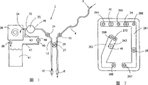
For the purpose of this narration, will specifically be used to wash or the fluid circuit at the position of a surgery of sucking-off comes fluid flow control system of the present invention is carried out in conjunction with one.At first indicate with label 2 with reference to 1, one fluid flow line integral body that can combine with the eye surgical procedure and use of figure.Fluid flow line 2 comprises one first tubular passageway 4, and it is suitable for receiving the supply of flush fluid (for example saline), and this flush fluid is received in this first tubular passageway, 4 inside via a supply entrance region 6.This first tubular passageway 4 ends in a discharge nozzle 8, and in order to wash purpose, but position mat one surgeon of this discharge nozzle 8 or other operation assistants are controlled.Between this supply entrance region 6 and this discharge nozzle 8, be formed with one first valve body control point 10.As what will set forth in more detail hereinafter, a precalculated position is set up in the first valve body control point 10 in first tubular passageway 4 that can be controlled fluid flow wherein.
Fluid flow line 2 also comprises one second tubular passageway 13, comprises an entry nozzle 16 at the one end.In flow line 2, the entry nozzle 16 and second tubular passageway 13 are the purposes that are used for sucking-off.Apart from entry nozzle 16 at a distance, second tubular passageway 13 is linked to an import 18 of a pressure transducer 20.Define one second valve body control point 24 along second tubular passageway 13.Second tubular passageway 13 can be connected to Fig. 1 tubular passageway 4 via a ventilation line 27.As shown in the figure, if be provided with ventilation line 27, then this ventilation line 27 will have one the 3rd valve body control point 29 that is attached thereto.
Pressure transducer 20 has an outlet 32, and it is connected to an import 34 of a pump 36.As what will set forth in more detail hereinafter, pump 36 can the many known types of mat the pumping unit constitute, yet 5, in preferred embodiment, scroll-type fluid means of pump 36 mats constitutes, this scroll-type fluid means has one from one milliliter of outlet flow rate to 60 milliliters of per minutes of per minute, the max vacuum pressure of about 550 millimetress of mercury.Specifically, preferred embodiment has a kind of scroll-type fluid means described in the U.S. patent application case " small-sized scroll-type fluid means " of filing an application on the same day in this case at Ronald J.Forni.With a kind of similar methods, pressure transducer 20 can take various forms according to the present invention, but better is in the U.S. patent application case of filing an application on the same day with this case by Reed and Franzosa " the fluid pressure sensing unit " described in mode constituted.Though pressure transducer 20 is not considered some of the present invention with the particular configuration of pump 36, for the event of integrity, herein, with the explanation of these two application cases that await the reply jointly usefulness as a reference cited in this article.
Pump 36 has a coupled outlet 38, and described outlet is communicated with storage groove 41 fluids.The outlet 32 of pressure transducer 20 also links to each other with one first end 43 of a calibrated conduit 45.Calibrated conduit 45 comprises one for second end 47 that enters this storagetank 41.In these calibrated conduit 45 inside, between first end 43 and second end 47 is a normally closed pressure calibration valve body that indicates with label 49.Calibrated conduit 45 and continuous valve body thereof 49 only the purpose of integrity and involved, and can be used for calibrating this pressure transducer 20, yet, when pressure transducer 20 does not need these more punctual, can think that this is not an essential characteristic of the present invention.
The present invention one main aspect relates to can constitute one with a small-sized and assembly that economized form is made with each structure member of fluid flow line 2 and one.Because showing the parts of total, fluid flow line 2 will be subjected to possible pollution at the surgery intra-operative, these parts are packed into not only can make in the integral component these parts isolate with other system parts (do not need to be directly exposed to flow through the different fluid of pipeline 2 in) easily, and can effectively change a used assembly, and after disposable use, it is handled, and this is connected on and hereinafter becomes more clear.
Now see also Fig. 2 to Fig. 6, it has described the structure that can abandon casket shell 52, and this can abandon casket shell 52 and be designed to make one with the parts of fluid flow line 2.Can abandon casket shell 52 and comprise one first housing parts 54 and one second housing parts 56, these two parts are suitable for along a girth seam 58 and are together connected to each other.In preferred embodiment, first housing parts 54 and second housing parts 56 be by plastics institute model, and combine at seam 58 places via a welding operation.Certainly, other binding configuration (comprising mechanical fixed part or sticker) also can be used.
As can know among Fig. 4 to Fig. 6 see, first housing parts 54 comprises the rectangular substantially outer surface of a shape 60, but it is provided with a semicircle downside extension 62.With this semicircle downside extension 62 part of being separated by, the outer surface 60 of first housing parts 54 is formed with a perforation 64, and is formed with first, second, third and the portion's connector 66-69 all round at the upper portion of first housing parts 54.In preferred embodiment, each outside connector 66-69 all defines with axial separately, a roughly cylindrical element 71-75 with a central perforation 76-79.Outside connector 66-69 is fit to interconnect with being connected to this pipe fitting that can abandon casket shell 52 or other fluid conduit systems (not showing), in order to finish fluid flow line 2.For by preventing that the possible error of people when finishing pipeline from guaranteeing suitable connection, in preferred embodiment, outside connector 66-69 is of different sizes, and these sizes are corresponding with the size of each conduit of desiring to be connected to this outside connector.
The second outside connector 67 is actually that mat cylindrical elements 72 defines, this cylindrical elements has constituted an inboard cylindrical elements 77 and an outside cylindrical elements 82, they are separated by an annulus 85, as being clear that among Fig. 4.Each outside connector 66,68 and 69 is suitable for having the tubular conduit that matches with its each cylindrical elements 71,73 and 74, simultaneously, a conduit is suitable for inserting 85 inside, annulus and also centers on inboard cylindrical elements 72 settings of the second outside connector 67 to be communicated with central perforation 77 fluids.At last, outer surface 60 also is formed with a pair of hanging element of being separated by 88 and 89, and this will set forth hereinafter in more detail, and this hanging element 88 and 89 is to use from abandoning casket shell 52 to hang sack or other a container (not shown) that defines storage groove 41.In preferred embodiment, this hanging element 88 and 89 includes an outside projection 91 and an axial bond sheet part 93.When a tubulose sack was used as storage groove 41, this sack better was provided with the separation perforation that is used for from this hanging element 88 and 89 these sacks of suspention.
First housing parts 54 has an inner surface 95, as being clear that among Fig. 5.Inner surface 95 is formed with the interior annular flange 99 that 96, one of a pair of box-shaped openings extend around around the whole inboard of first housing parts 54 at this hanging element 88 and 89 places, and several open channels that indicate with label 102,103 substantially.The unlifted wall part 104 that path 10 2 and 103 is actually mat inner surface 95 defines.As shown in the figure, open channel 102 comprises one first end 106, and it extends along a sidewall sections 110 downwards along a upper wall portion 108 of first housing parts 54, then in second end, 112 places of a contiguous perforation 64 termination.Open channel 103 has first end 114 that is configured in contiguous perforation 64 places, and is being thereafter to be divided into the subchannel 116 and 117 with terminating end 118 separately and 119.As from can being clear that this figure, open channel 102 is formed with first, second and the 3rd hole 121-123 at upper wall portion 108 places, and open channel 103 then is to be formed with one the 4th hole 124 at terminating end 119 places.The central perforation 76-79 that hole 121-124 is actually the outside connector 66-69 of mat defines, so path 10 2 and 103 is open to the outside that can abandon casket shell 52.At last, the inner surface 95 of first housing parts 54 better is provided with several and strengthens flank, and one of them flank indicates with label 126.
Specifically see also Fig. 2, Fig. 3 and Fig. 5, second housing parts 56 comprises that one has the outer surface 129 of top female 132, and wherein this female 132 is with an inwardly reduction and the annular wall 134 that guides to a bottom 136 defines.Bottom 136 is radially inner to be one and to extend upward and inwardly reduce wall 138, and it leads to a central annular flange 139 that is provided with an opening 140.Second housing parts 56 separated place below this female 132 is provided with a lower opening 143, and this opening has defined an interior annular support surface 145.Outer surface 129 also is provided with a plurality of separation perforation 147-150, these whole second housing parts 56 that extend through of boring a hole.
As shown in Figure 6, second housing parts 56 has an inner surface 152, protrudes out many upright inner wall element 154-160 from it.When consideration was relevant with the valve body type in this preferred embodiment, upright inner wall element 154-156 had finished will become hereinafter more obvious structural intergrity and valve components guiding function.Yet, this the aspect on, it must be appreciated that perforation 147 and 148 is to be located between the upper wall 161 and wall elements 154 of second housing parts 56, perforation 149 is to be configured between the sidewall (not shown) and wall elements 155 of second crust component 56, and to bore a hole 150 be to be positioned between the opposite side walls (not giving label) and wall elements 159 of second crust component 56.Upright inner wall element 154 better is formed with one and relies on pawl element 162, and as will setting forth in more detail hereinafter, this pawl element 162 can be pump 36 help of an aligning with installing is provided.In second crust component, 56 inside, the bottom 136 of lower limit part 132 is to have defined a rise surface 164, extends an annular wall 167 that has a upper limb 168 and be formed with a groove 169 from it.Groove 169 is suitable for receiving an O shape ring (not shown) that partly seals that is used to pump 36.
Being installed between first housing parts 54 and second housing parts 56 is an elastic sheet 177, can be clear that described elastic sheet from Fig. 5 and Fig. 6.Elastic sheet 177 is extremely flexible and soft, and comprises that one is formed with first side 179 of many upright sealed walls 181, and the sealing wall is fit to match hermetically with 103 unlifted wall part 104 with path 10 2, in order to define several fluid flow passages.Specifically, the upright sealed wall 181 of elastic sheet 177 has defined a last square channel 183 and a below channel part 187 that guides to a sidewall 185.Below channel part 187 ends in one around an opening 190 formed walls 189 places.In addition, upright sealed wall 181 has also defined mat one upstanding wall 193 and has been divided into the below channel part 191 of subchannel part 195 and 196.
Elastic sheet 177 also is provided with several perforation 197-200.Specifically, one first perforation 197 is located at contiguous termination wall 189 places in the channel part 187 of below, one second perforation 198 is located at channel part 191 adjacent wall 189 places, below, and the 3rd and the 4th perforation 199 and 200 is located at the terminating end place of subchannel part 195 and 196 respectively.On second side 201 of elastic sheet 177, each perforation 197-200 has coupled upright sealing ring 204-207 respectively.
As mentioned above, pump 36 better mat one scroll-type fluid means and constituting are to indicate the scroll-type fluid means with label 211 in diagram.Though also can use the pump of various other known types and the particular configuration of scroll-type fluid means 211 be not thought of as some of the present invention,, in general, scroll-type fluid means 211 comprises a pair of linking swirl elements 214 and 216.Do not illustrate though give among the figure, in having, first and second swirl elements 214,216 are connected involute spiral winding element, they can form at least one fluid chamber, when one of them wound element during around the operation of orbit centre, can move to one from a pump inlet district and pump oral region along a circular path with respect to another wound element.According to the preferable configuration of scroll-type fluid means 211, when it belonged to the assembly that can abandon casket shell 52, first swirl elements 214 comprised an exposed side 217 that is formed with a center hub 218, and this center hub then is provided with a perforation 220.In addition, exposed side 217 is formed with a ring-shaped groove 222, and it is suitable for receiving one and is used to be sealed to the O shape ring of first crust component 54 or the sealing member (not shown) of another known type with making first swirl elements, 214 fluids, and this will describe in detail hereinafter.Second swirl elements 216 comprises a flange 226 that extends radially outwardly from first swirl elements 214, and flange 226 comprises a surrounding edge 228, and described surrounding edge is formed with a upstanding flange 230 with a central indentation 232.As being clear that among Fig. 6, second swirl elements 216 has an exposed side 235, and described exposed side is formed with the annular recess 238 and 238 and defined central upright adapter 240 and 241 of a pair of separation. Upright adapter 240 and 241 is actually and has defined outlet and the import that is used for scroll-type fluid means 211.
Be arranged on can abandon casket shell 52 inside also have one can abandon pressure sensor 244, it is actually the some that has constituted an integral pressure sensory package, and wherein this integral pressure sensory package is better according to above-mentioned and merge into by mode described in the U.S. patent application case of reference and constitute.As shown in the figure, pressure sensor 244 comprises a shell 247 that is better formed by plastics, but it is sealed in a deflection dividing plate 249 that is preferably formed by rustless steel.Shell 247 is formed with central authorities and is located in protuberance 252 and a pair of relative fluid flow adapter 255 and 256, and this fluid flow adapter 255 and 256 has constituted the import and the outlet of pressure transducer 244, is used for making through the Zhi Liuti of system flowing.
To shown in Figure 6, first and second housing parts 54 and 56 that can abandon casket shell 52 is fit to interconnect with the elastic sheet 177, scroll-type fluid means 211 and the pressure transducer 244 that are placed in wherein as Fig. 2.Specifically, elastic sheet 177 better is the inner surface 95 that is fixed to first housing parts 54 with adhering, so that elastic sheet 177 can extend across open channel 102 and 103 hermetically, so that these passages only form at hole 121-124 place's opening and pass the fluid-encapsulated flow channel of hole 197-200.Specifically, the upright sealed wall 181 of elastic sheet 177 is actually and is received in one around open channel 102 and 103 formed continuous channels, 260 inside.Scroll-type fluid means 211 is to be positioned among second housing parts 56, and ring-shaped groove 222 is to be located on the rise surface 164 and center hub 218 is to protrude to enter in the opening 140.Center hub 218 has one and is little diameter than opening 140, moves at the not obstruct track of 211 operating periods of scroll-type fluid means in order to allow first swirl elements 214.Second swirl elements 216 also is located in second housing parts, 56 inside, and flange 226 is located in thereon with being positioned at the O shape ring in this high groove 169, and upstanding flange is and upright inner wall element 154 adjacency substantially.In addition, the indentation 232 that is located on second swirl elements 216 has received pawl element 162, in order to help the aligning and the installing of scroll-type fluid means 211.Pressure transducer 244 is positioned at lower opening 143, and dividing plate 249 is exposed to outer surface 129 places of second crust component 56.In addition, the adapter 255 of pressure sensor 244 matches with 205 with the upright sealing ring 204 of elastic sheet 177 with 256, and central authorities be located in protuberance 252 extend through opening 190 and enter into the perforation 64.And, the upright sealing ring 206 of elastic sheet 177 and 207 and the upright adapter 240 and 241 of central authorities of scroll-type fluid means 211 interconnect.
Should be clear that very much from above explanation, scroll-type fluid means 211 is installed in hermetically can abandon casket shell 52 inside, and have import and export (being import in the preferred embodiment that is disclosed), these import and export are communicated with the flow passage fluid that the mat chap passage 118 and the combination of elastic sheet 177 are defined by using upright sealing ring 207.With a kind of similarity method, the adapter 240 that has defined an outlet of scroll-type fluid means 211 is to be connected to subchannel 117 via upright sealing ring 206 at the 4th hole 124 places.And the 4th hole 124 leads to connector 69.As mentioned above, a storage groove 41 that presents with a sack form is suitable for suspending in midair from hanging element 88, and is connected to connector 69 so that lead to storage groove 41 from the outlet of scroll-type fluid means 211.The import of pressure sensor 244 and outlet also with mat open channel 102 with 103 and the fluid passage that defined of elastic sheet 177 via adapter 255 with 256 and first and second bore a hole 197 with 198 fluid is communicated with.Upright sealing ring 204 provides a complete sealing with 205 in this fluid is communicated with.
Therefore, in case combination can be abandoned the casket shell and can set up the whole fluid flow line that indicates with label 2 among Fig. 1.This may can the most clearly find out in Fig. 7, and wherein circulation flow path 261-263 is established and fluid passage 261 is to receive a fluidic source of supply (be used in the embodiment that is disclosed flushing) at point 264 places at least; The export supply of flush fluid provides at 265 places; The inlet flow of sucking-off fluid (wherein may be suspended with microgranule) is positioned in label 266 places and is communicated with flow passage 261 fluids; Stream originally can 267 flow to pressure sensor 244 in the position from fluid passage 261; Flowing is that pressure sensor 244 is left at 268 places in the position; Inlet fluid to scroll-type fluid means 211 is to take place at point 269, represents one to export storage groove 41 to and put 270.First, second and the 3rd valve body control point 10,24 and 29 are also pointed out as a valve body point that is used to calibrate valve body 49.As what will at length set forth hereinafter, elastic sheet 177 oppressed its positions of extending that make are represented in these valve body point positions in the particular of fluid flow passages 261 and 263, in order to selectively to control the fluid flow via these paths.Flexible and softish material is formed because elastic sheet 177 is by one, and in fact, sheeting itself can be used to carry out the function of valve body, so that this thin slice deflection, this will do more detailed elaboration hereinafter together with this element of valve of use.In any case, about this point, should be clear that very much, can abandon the integrated assembly that casket shell 52 provides parts, as the same fluid flow inside pipeline that only needs to make some parts, in order to finish whole pipeline at connector 66-69.Should be clear that very that these outside connector 66-69 and label mentioned above are that 264,265,266 and 267 pipe fitting coupling position is directly corresponding.
Now see also Fig. 8 to Figure 12 and narrate a control module 277, it with can abandon casket shell 52 and cooperate mutually to form whole fluid flow control system of the present invention.As shown in the figure, control module 277 comprises a main main part 279 and a delivery main part 281.Delivery main part 281 comprises a header board 284, side plate 286 and 287, a lower plate 289, a median plate 291, a reward plate portion 293 and a back plate 295, and this can the most clearly find out from Fig. 8 and among Figure 12.In preferred embodiment, delivery main part 281 is made of metal, and then plate 295 is made of aluminum, and the remainder of delivery main part 281 is formed by thin sheet of metal.Between header board 284 and median plate 291, delivery main part 281 has formed a casket shell joint and has received zone or slit 298, and this is with more detailed description hereinafter, and it is suitable for receiving can abandon casket shell 52.In preferred embodiment, header board 284 comprises a below opening 300, and the spring element with at least one deflection fingers 303 with arc terminating end 305 (for the sake of clarity do not give illustrating among Fig. 8, but can see from Fig. 9, Figure 10 and Figure 12) is by fixed upright this opening 300 that passes.Median plate 291 and back plate 295 comprise a upward perforation 307 and 308 of aiming at and separating.In fact, median plate 291 and back plate 295 are provided with four these perforation, and two perforation in addition are configured in median plate 291 belows.The position and the purpose of each these overpunch will become better apparent hereinafter.
Median plate 291 also is formed with a central opening 312, and several arcuate slots 314-317 divide around this opening across.Median plate 291 and back plate 295 have also formed rear, a below opening 319 that is formed in the delivery main part 281.That be close to its four perforation substantially from 295 suspensions of back plate is each guide rail 322-325.As will more at large setting forth hereinafter, track 322-325 is supporting person with main main part 279 and slidably, and its effect is to guide to deliver main part 281 between delivery main part 281 and main main part 279 during moving.
Shown in the preferred embodiment, main main part 279 comprises a bottom plate 327, a header board 328, a back plate 329, a upper plate 330 and at least one side plate 331.In preferred embodiment, plank 327-331 is made of aluminum, and interconnects with traditional mechanical fixture (not shown).Mating holes and accurate hole 334,335, back wherein are positioned with each axle sleeve 337 that preferably is made of plastics be formed with each near each corner of header board and back plate 334 and 335 before.Be extended with guide rail 322-325 separately in each axle sleeve 337 inside.As can being clear that in Figure 10 to Figure 12 at least, each includes a corresponding end 340 that extends out to outside the back plate 329 guide rail 322-325.Because this set, delivery main part 281 is the supportings slidably via abundant guideway 322-325 of the main main part 279 of mat, and delivery main part 281 is to move at least one section distance that length defined by end 340 towards header board 328 or away from this header board 328.As what will be hereinafter more at large discuss, delivery main part 281 makes delivery main part 281 can take as position in the shown extension casket shell carrying/unloading position of Fig. 9 and in as use shown in Fig. 1 O and Figure 12 with respect to moving of main main part 279.
Delivery main part 281 is according to the present invention with respect to the displacement of main main part 279 and one on mat is performed with the mechanism that label 342 indicates substantially.Mechanism 342 better is made of a bidirectional linear electro-motor 343, but this electro-motor has a continuous vertical shift axle 345, this extend through one be located at the back in the plate 329 opening 347 and the axle sleeve 349 in hole 350 that is located at header board 328.The front end 352 of axle 345 is linked to the back plate 295 of delivery main part 281 in order to rotate relatively.Because this set, the actuating of linear motor 343 cause axle 345 rotations, for example pass a helical gear driving device or worm-gear driven device, so that axle 345 can be shifted linearly with respect to main main part 279.Owing to axle 345 can rotate with respect to back plate 295, therefore only there is the vertical shift of axle 345 to move and to be converted to delivery main part 281.When linear motor 343 can be operated on twocouese, during can and using in delivery/unloading position, delivery main part 281 positively drives between the position.About this point, can be appreciated that easily, though mechanism 342 is made of a linear motor and mechanism driving device configuration, but, also can under the situation of not leaving spirit of the present invention, use the linear drive system (comprise helical is pneumatic and the actuator that surges) of different other types.
Main main part 279 also is equiped with a pump drive motor 255 therein, and this motor comprises an encirclement shell 356 with an output driving shaft 357.As what can be clear that in Figure 12, output driving shaft 357 is to be connected with an adapter 358 drivingly thereon, and this adapter has a female connector element 359 and an outconnector element 360.Outconnector element 360 comprises a bell part 361.In preferred embodiment, drive adapter 358 and in fact constitute a basic axle sleeve in order to the moving scroll-type fluid means 211 that is sent to.Specifically, outconnector element 360 is suitable for being received in center hub 218 inside of first swirl elements 214, and in order to drive scroll-type fluid means 211 in the carrying that can abandon casket shell 52, its mode will describe in detail hereinafter.In fact pump drive motor 355 comprises a front casing part 362, and it is installed up to a middle body 363 of an aligning axle sleeve 364.In fact the middle body of this aligning axle sleeve 364 comprises one first diameter parts 365 and one second reduction diameter parts 367, and front end 362 adjacency second of stream CD-ROM drive motor 355 are reduced diameter parts 367 and are fixed to Fig. 1 diameter parts 365, as what clearly illustrated in 12.Aim at axle sleeve 364 and itself be and be fixed in the opening 368 that is located at header board 328.Aim at axle sleeve 364 and have an interior cylindrical sleeve 369 and an Outer cylindrical sleeve 371 that protrudes forward, it has the different cut-out 372-375 that separate on every side.Interior cylindrical sleeve 369 aligns with central opening 312, and the different piece of Outer cylindrical sleeve 371 aligns with arcuate slot 314-317 respectively.Because this set, when delivery body element 281 directly be displaced to its use in when position and contiguous main main part 279, interior cylindrical sleeve and Outer cylindrical sleeve 369 and 371 protrude and enter narrow shell joint receipts regional 298.For the cause of discussing more completely hereinafter, Outer cylindrical sleeve 371 has the forward edge 376 of a reduction, as what clearly illustrate in Figure 12.
Main main part 279 also is supported with a fixed pressure sensing element 377.As at Fig. 8 and illustrated in fig. 12, fixed pressure sensing element 377 comprises a vacuum pipe fitting part 378, and it has an enlarged diameter head 380 and an annular lip 382.Fixed pressure sensing element 377 is fixed to header board 328 regularly via annular lip 382, and has a termination bearing 384 with O shape ring 386, pressure sensor 244 is supporting this O shape ring 396 and the person of being located in, this is to be to be placed on the inner and delivery main part 281 of delivery main part 281 when moving in the use position abandoning casket shell 52, as shown in figure 12.Fixed pressure sensing element 377 also comprises a sensing unit that indicates with label 387, it be suitable for being positioned with dividing plate 249 side by side, be exposed to deflection in the fluid system pressure in order to induction dividing plate 249 based on it.Though be not presented at for purpose clearly in these diagrams, fixed pressure sensing element 377 also is equipped with electronic control part in pipe fitting 378 inside, in order to receiving signal, to be used for determining fluid system pressure based on moving of sensed dividing plate 249 in fluid flow line 2 from sensing unit 387.As already pointed out, though the configuration of preferable pressure transducer is to be disclosed in before to mention and in the U.S. patent application case of quoting as a reference, the sensor cluster of different known types can be used to carry out desired pressure sensitive function according to the present invention.
The main main part 279 of control module 277 also is supported with different valve body unit, and one in these valve body unit indicates with label 389 substantially.According to preferred embodiment of the present invention, therefore valve body unit helical valve body of 389 supportings also comprises a helical shell 391, for example be via use one substantially U-shaped carriage 393 and be fixed among the main main part 279, this U-shaped carriage 393 has a pedestal 395, this pedestal 395 is fixed to header board 328, and shank part 397 and 398 is then had several fixtures 399 of mat and is linked to helical shell 391.Each valve body unit 398 comprises a linear displacement valve components 401, and it presents with a rod member form with reduction most advanced and sophisticated 405.Each valve components is installed among the guide sleeve 407 slidably, and perforation 409 that is formed in the header board 328 of these guide sleeve 407 extend pasts.In fact, in preferred embodiment of the present invention, four these solenoid valve body units 389 are to be set up, and each solenoid valve body unit 389 has an associated valve body member 401 that extends through header board 328, and can be shifted linearly.The reduction tip 405 of each valve components 401 is suitable for extending through one that discusses hereinbefore in the perforation 307 and 308 that is formed in the delivery main part 281, and follows to enter at perforation 147-150 place respectively and can abandon casket shell 52.When delivery main part 281 when being arranged in the use position, reduction most advanced and sophisticated 405 can be respectively at the first, second, third and the 4th valve body control point 10,24,29 and 49 places be connected elastic sheet 177.Additional detail about each valve body unit 389 will be discussed in the mode of narration fluid flow control system operation of the present invention now.
When surgical procedure of preparation, control module 277 will initially be rendered as carrying/unloading position illustrated in fig. 9.Certainly, main main part 279 will have certain type of outer side covers, not show for the internal structure that control module 277 is described in detail in detail.In any case in this position, delivery main part 281 is separated mutually with the main main part 279 that is supported via guide rail 322-325.In this position, aim at each valve components 401 of axle sleeve 364 and valve body unit 389 and can clear up casket shell joint receipts zone 298.As mentioned person above, delivery main part 281 can mat linear motor 343 and axle 345 to the connection of back plate 295 and carrying/the unloading position so far that is shifted.As what clearly illustrate, drive adapter 358 and also receive zone 298 separation mutually with the casket shell joint.At this some place, the new casket an abandoned shell 52 can be seated in the casket shell joint easily and receive among the zone 298, and the central authorities of pressure sensor 244 are located in protuberance 252 and can locate fingers 303 to spring element 301, and outside connector 66-69 extends above the header board 284 of delivery main part 281.In preferable setting order, before can abandoning casket shell 52 insertion casket shell joints receipts zones 298, a storage sack will as the 4th connector 69, be linked to and can abandon casket shell 52 at hanging element 88 and 89 places.
In case can abandon casket shell 52 is to be positioned at appropriate position, an operator will press next actuating linear motor 343 and cause delivering the button (showing) that main part 281 sucks towards main main part 279, so that control 277 are the positions (be not have casket shell 52 in Figure 10 and Figure 11, and casket shell 52 being to be positioned at appropriate position in Figure 12) that present in use.Perhaps, casket shell 52 can be received at insertion casket shell joint and be connected a switch at regional 298 o'clock, in order to automatically to cause delivering the displacement of main part 281.When delivery main part 281 is inhaled into main main part 279, pressure sensor 244 automatically is located in to the O of fixation pressure sensing element 277 shape ring 386, driving adapter 358 automatically is positioned among the center hub 218, the interior cylindrical sleeve 369 of aiming at axle sleeve 364 is configured in 312, the Outer cylindrical sleeve 371 of aiming at axle sleeve 364 extends through arcuate slot 314-317, till a upwardly extending inside reduction wall 138 is being supported in reduction forward edge 376 location, wherein inwardly reduction wall 138 is formed in second housing parts 56 that can abandon casket shell 52 and each valve components 401 extends through the back plate 295 and header board 284 of delivery main part 281, and enters via indivedual perforation 147-150 and can abandon in the casket shell 52.Thereafter, connection can be as mentioned above externally connector 66-68 finish.
Here, fluid flow control system of the present invention is exercisable.During program, pump drive motor 355 can be controlled to operate scroll-type fluid means 211, in order to produce the suction via flow passage 262, pressure sensor 244 and fluid passage 261 at the 3rd junction point 68 places.Certainly, when the output of scroll-type fluid means 211 directly is communicated with external connecting 69 fluids with the perforation 199 of elastic sheet 177, directly is sent to from the fluid of scroll-type fluid means 211 suctions and preserves groove 41.Calibration valve body 49 is normally closed, and in the preferred embodiment that is disclosed, this so that cone point 405 compressing elastic sheets 177 take place, and can make the elastic sheet 177 prevent fluid flows body path 263 by extending a valve components 401.The valve body control of this type also can be located at first, second and reach the 3rd valve body control point 10,24 and 29.When needs wash, fluid is flowed in flow passage 261, make the first and second outside connectors 66,67 fluid communication with each other (fluid freely be flowed, as shown in Figure 7) between point 264 and 265 thus.Because ventilation line 27 is normally closed, the valve components 401 that links to each other with the 3rd valve body control point 29 generally is a full extension.
In using the process of fluid flow control system of the present invention, the operation of pump drive motor 355 and valve body unit 389 is actually according to preferred embodiment and electric control.Specifically, an electronic control unit 417 is set, to receive the input from an operation control element (for example being a pedal) that indicates with label 420, a manual operator scheme is controlled switch 422, and from the signal of sensing unit 387.Electronic control unit 417 uses these signals control signal is exported to each pump drive motor 355, linear motor 343 and valve body unit 389.Foot-operated my controller 420 is according to those skill known in the prior art and by construction, and makes that a surgeon can be as required and control flushing and sucking-off.Whether operator scheme control switch 422 can be used to select control module 277 can provide one to build flushing flow rate, to have controlled the flushing vacuum pressure still be both.If a system based on flow rate is desired, operator scheme control switch 422 can suitably be set, and pump drive motor 355 will thus can via a kind of similar in appearance to known wriggling type system mode and control.On the other hand, operator scheme control switch 422 can be positioned in the operator scheme based on vacuum, wherein electronic control unit 417 will be according to the signal that is not only received from pedal 420, and comes operating pumps CD-ROM drive motor 355 according to the signal from the sensing unit 387 that links to each other with fixation pressure sensing element 377.In this pattern, control module 277 will be with a kind of mode effect similar in appearance to known Wen's type system.When in a pattern, operating based on pressure, if appearing in the clean-up line, obstruct make the increase of cask washing pressure exceed a marginal value, then electronic control unit 417 will be shut.In addition, when in a flow rate pattern, operating, electronic control unit also will be sensed high rotating speed to be increased, and high rotating speed increase is to cause owing to intercepting in flushing line, and this is because this contour rotating speed increase may cause loosening of suction after obstruct is to be removed.In this pattern, electronic control unit 417 will be therefore still responsive to pressure signal, to avoid this possible problem.
Though preferred embodiment above of the present invention relatively is described,, can be appreciated that easily, can also make all variation and/or improvement that does not deviate from spirit of the present invention to the present invention.For example, though fluid flow control system of the present invention is special in setting up the mobile control piper of an integral body flushing/sucking-off and narrate,, can be appreciated that easily that principle of the present invention is to be applied in the other field.

Claims (46)

1. fluid flow control system is characterized in that it comprises:
One can abandon the casket shell, and it comprises:
One casket shell shell, it is formed by at least two housing parts that link together, and this housing parts is provided with at least two fluid connectors and the opening that this casket shell enclosure is come out,
A pump, it has continuous import and outlet, and at least one removable pump element is provided with one and is suitable for being used to operate this pump with the interconnective link component of a driving element, and this pump is positioned in this casket shell enclosure, and this link component is located in this opening part, and
One resolution element, it is positioned among this casket shell shell, and this resolution element has formed several flow passages at least in part, and these several flow passages are communicated with the import and the outlet fluid of described two fluid connectors and this pump respectively at least, and
One control module, it comprises:
A control shell, it has a main main part and a delivery main part, and this delivery main part forms one and is suitable for receiving this casket shell joint that can abandon casket shell receipts zone,
A driver element, but it comprises that one is suitable for being connected to drivingly the driving element that is somebody's turn to do link component of this pump, then this can be abandoned the casket shell and insert in this casket shell joint receipts zone, and
The operation that is used to control this driver element is in order to the mechanism of the operation of regulating this pump.
2. fluid flow control system as claimed in claim 1 is characterized in that: described resolution element is made of a flexible thin sheet.
3. fluid flow control system as claimed in claim 2 is characterized in that: described flexible thin sheet is formed by an elastomeric material.
4. fluid flow control system as claimed in claim 1 is characterized in that: described at least two shells in partly is formed with several open channels, this open channel by the covering of this resolution element in order to form this several flow passages.
5. fluid flow control system as claimed in claim 4 is characterized in that: described resolution element is formed with different unlifted walls, and this unlifted wall matches with this open channel hermetically.
6. fluid flow control system as claimed in claim 1, it is characterized in that: it also comprises a pressure transducer, this pressure transducer comprises that the sensor element abandoned and that is located in this casket shell shell is arranged on the sensor element reused in this control shell, this can abandon sensor element and this, and can to reuse sensor element arranged side by side, then this can be abandoned the casket shell and insert this casket shell joint and receive in zone.
7, fluid flow control system as claimed in claim 6 is characterized in that: the described sensor element of abandoning comprises a fluid inlet, and it can be via this resolution element be connected with in several fluid passages of fluid and this at least one.
8. fluid flow control system as claimed in claim 1, it is characterized in that: one in described several flow passages is to interconnect with these at least two fluid connectors, in order to provide fluid can abandon flowing of casket shell via this, this is irrelevant with the operation of this pump.
9. fluid flow control system as claimed in claim 1 is characterized in that: described pump has constituted a plastics scrollwork fluid means.
10. fluid flow control system as claimed in claim 1, it is characterized in that: it comprises that also several are formed on separation perforation in this casket shell shell and several and can be installed in valve components on this control shell with being shifted, each this valve components is to be suitable for extending into discrete one to separate perforation, and is suitable for intercepting flowing through a predetermined portions of this flow passage.
11. fluid flow control system as claimed in claim 10 is characterized in that: described valve components is to have constituted linear solenoid valve body unit.
12. fluid flow control system as claimed in claim 10, it is characterized in that: described resolution element is by the former of elastomeric material institute, and each this valve components is to be suitable for causing the particular of this elastomeric material to protrude to enter a predetermined portions of this flow passage, thereby of having intercepted in this flow passage is flowed.
13. fluid flow control system as claimed in claim 1, it is characterized in that: it also comprises the mechanism that this delivery main part that is used for making this control shell is shifted between a casket shell carrying/unloading position and use position, wherein this delivery main part is to separate with this main main part phase-splitting at this casket shell carrying/unloading position place, and this delivery main part is that the position is shifted towards this main main part in this use.
14. fluid flow control system as claimed in claim 13, it is characterized in that: it also comprises several orbit elements, this orbit element is to be connected to this delivery main part and is to be received in slidably in this main shank of this control shell that this orbit element is that this delivery main part of guiding is in order to move between the position in this casket shell carrying/unloading position and this use.
15. fluid flow control system as claimed in claim 1, it is characterized in that: described casket shell shell comprises that is provided with an antetheca that is suitable for supporting the unitary suspension elements of a storage groove, and one in these at least two fluid connectors makes this storage groove unit to be connected to this flow passage with fluid.
16, a kind of casket abandoned shell that is used for a fluid flow system is characterized in that it comprises:
One casket shell shell, it is formed by at least two housing department branch that link together, and described housing parts is provided with at least two fluid connectors and the opening that this casket shell enclosure is come out,
One pump, it has continuous import and outlet, and at least one removable pump element is to be provided with one to be suitable for being used to operate this pump with the interconnective link component of a driving element, this pump be positioned in this casket shell shell in and this link component is to be located in this opening part, and
One resolution element, it is positioned at this casket shell enclosure, and this resolution element has formed several flow passages at least in part, and these several flow passages are import and the outlets that are connected to these at least two fluid connectors and this pump respectively with fluid.
17. the casket shell of abandoning as claimed in claim 16, it is characterized in that: described resolution element is made of a flexible thin sheet.
18. the casket shell of abandoning as claimed in claim 17, it is characterized in that: described flexible thin sheet is formed by an elastomeric material.
19. the casket shell of abandoning as claimed in claim 16 is characterized in that: described at least two shells in partly is formed with several open channels, this open channel by the covering of this resolution element in order to form described several flow passages.
20. the casket shell of abandoning as claimed in claim 19, it is characterized in that: described resolution element is formed with different unlifted walls, and this unlifted wall matches with this open channel hermetically.
21. the casket shell of abandoning as claimed in claim 16 is characterized in that: it also comprises a pressure sensor abandoned that is located in this casket shell shell.
22. the casket shell of abandoning as claimed in claim 21 is characterized in that: the described sensor element of abandoning comprises a fluid inlet, and it can be via this resolution element be connected with in several fluid passages of fluid and this at least one.
23. the casket shell of abandoning as claimed in claim 16 is characterized in that: in described several flow passages one interconnects with these two fluid connectors at least, can abandon flowing of casket shell in order to fluid to be provided via this, and the operation of this and this pump has nothing to do.
24. the casket shell of abandoning as claimed in claim 16 is characterized in that: described pump constitutes a plastics scrollwork fluid means.
25. the casket shell of abandoning as claimed in claim 16, it is characterized in that: it comprises that also several are formed on the separation perforation in this casket shell shell, each this separation perforation is suitable for receiving other valve components one by one, is used to intercept flowing through a predetermined portions of this flow passage.
26. the casket shell of abandoning as claimed in claim 16, it is characterized in that: described casket shell shell comprises that one is provided with the antetheca that is suitable for supporting the unitary suspension elements of a storage groove, and one in these at least two fluid connectors makes this storage groove unit to be connected to this flow passage with fluid.
27. a fluid flow control system is characterized in that it comprises:
Can abandon the casket shell for one, it comprises:
A casket shell shell, it is formed by at least two housing department branch that link together, this housing parts is provided with at least two fluid connectors, an internal fluid flow passageway pipeline and the opening that this casket shell enclosure is come out that is connected to this connector with fluid
A small-sized scroll-type fluid means, it is formed by plastics, this scroll-type fluid means is to have the removable operation element of import and outlet and at least one that links to each other that is connected with fluid and this internal fluid flow passageway pipeline, this removable operation element is to be provided with one to be suitable for being used to operate this scroll-type fluid means with the interconnective link component of a driving element, this scroll-type fluid means is positioned in this casket shell shell and this link component is to be located in this opening part, and
A control module, it comprises:
A control shell, it has a main main part and a delivery main part, and this delivery main part forms one and is suitable for receiving this casket shell joint that can abandon casket shell receipts zone,
A driver element, but it comprises that one is suitable for being connected to drivingly the driving element that is somebody's turn to do link component of this scroll-type fluid means, then this can be abandoned the casket shell and insert in this casket shell joint receipts zone, and
The operation that is used to control this driver element is in order to the mechanism of the operation of regulating this scroll-type fluid means.
28. fluid flow control system as claimed in claim 27 is characterized in that: it also comprises a resolution element, and it is positioned at this casket shell enclosure, and this resolution element forms this internal fluid flow passageway pipeline at least in part.
29. fluid flow control system as claimed in claim 28 is characterized in that: described resolution element comprises an elastic sheet.
30. fluid flow control system as claimed in claim 29 is characterized in that: described at least two shells in partly is formed with several open channels, this open channel by the covering of this resolution element in order to form this internal fluid flow passageway pipeline.
31. fluid flow control system as claimed in claim 27, it is characterized in that: it comprises that also several are formed on separation perforation in this casket shell shell and several and can be installed in valve components on this control shell with being shifted, each this valve components is suitable for extending into discrete one and separates perforation, and is suitable for selectively intercepting flowing through a predetermined portions of this internal fluid flow passageway pipeline.
32. fluid flow control system as claimed in claim 27, it is characterized in that: described internal fluid flow passageway pipeline and this at least two fluid connectors interconnect, flow in order to provide fluid can abandon one of the casket shell via this, the operation of this and this scroll-type fluid means has nothing to do.
33. fluid flow control system as claimed in claim 27, it is characterized in that: it also comprises a pressure transducer, this pressure transducer comprises that is located in the sensor element abandoned that is connected with this internal fluid flow passageway pipeline with fluid in this casket shell shell, and sensor element reused that is arranged in this control shell, this can abandon sensor element and this, and can to reuse sensor element arranged side by side, then this can be abandoned the casket shell and insert this casket shell joint and receive in zone.
34. fluid flow control system as claimed in claim 27, it is characterized in that: it also comprises the mechanism that this delivery main part that is used for making this control shell is shifted between a casket shell carrying/unloading position and use position, wherein should the delivery main part separate with this main main part phase-splitting, and this delivery main part position in this use is shifted towards this main main part at this casket shell carrying/unloading position place.
35. fluid flow control system as claimed in claim 27, it is characterized in that: described casket shell shell comprises that is provided with an antetheca that is suitable for supporting the unitary suspension elements of a storage groove, and one in these at least two fluid connectors makes this storage groove unit to be connected to this internal fluid flow passageway pipeline with fluid.
36, a kind of casket abandoned shell that is used for a fluid flow system is characterized in that it comprises:
A casket shell shell, it is formed by at least two housing department branch that link together, this housing parts is provided with at least two fluid connectors, an internal fluid flow passageway pipeline and the opening that this casket shell enclosure is come out that is connected to this connector with fluid
A small-sized scroll-type fluid means, it is formed by plastics, this scroll-type fluid means has the removable operation element of import and outlet and at least one that links to each other that is connected with fluid and this internal fluid flow passageway pipeline, this removable operation element is provided with one and is suitable for being used to operate this scroll-type fluid means with the interconnective link component of a driving element, this scroll-type fluid means be positioned in this casket shell shell in and this link component is located in this opening part.
37. the casket shell of abandoning as claimed in claim 36 is characterized in that: it also comprises a resolution element, it is positioned among this casket shell shell, and this resolution element has defined this internal fluid flow passageway pipeline at least in part.
38. the casket shell of abandoning as claimed in claim 37 is characterized in that: described resolution element comprises an elastic sheet.
39. the casket shell of abandoning as claimed in claim 38 is characterized in that: described at least two shells in partly is formed with several open channels, this open channel by the covering of this resolution element in order to define this internal fluid flow passageway pipeline.
40. the casket shell of abandoning as claimed in claim 36, it is characterized in that: it comprises that also several are formed on separation perforation in this casket shell shell and several and can be installed in valve components on this control shell with being shifted, each this valve components is suitable for extending into discrete one and separates perforation, and is suitable for selectively intercepting flowing through a predetermined portions of this internal fluid flow passageway pipeline.
41. the casket shell of abandoning as claimed in claim 36, it is characterized in that: described internal fluid flow passageway pipeline and this at least two fluid connectors interconnect, flow in order to provide fluid can abandon one of the casket shell via this, the operation of this and this scroll-type fluid means has nothing to do.
42. the casket shell of abandoning as claimed in claim 36 is characterized in that: it comprises that also is located in the sensing element abandoned that is connected with this internal fluid flow passageway pipeline with fluid in this casket shell shell.
43. the casket shell of abandoning as claimed in claim 36, it is characterized in that: described casket shell shell comprises that is provided with an antetheca that is suitable for supporting the unitary suspension elements of a storage groove, and one in these at least two fluid connectors makes this storage groove unit to be connected to this internal fluid flow passageway pipeline with fluid.
44, a kind of method of setting up a fluid flow system is characterized in that it comprises:
A casket shell that is equipped with a pump and defines several fluid flow passages is therein inserted among the delivery main part of a control module, and
This delivery main part is moved towards a main main part of this control module, use so that the driving shaft of this main main part branch supporting of mat can be connected to this pump drivingly.
45. method as claimed in claim 44 is characterized in that: it also comprises:
With a mat should the control module should be main the valve components that supports of main part branch, make it in this casket shell, extend to a fluid flow control position linearly with respect to one in this fluid flow passages.
46. method as claimed in claim 44 is characterized in that: it also comprises:
The fluid pressure of induction in this fluid flow control system, and
Selectively set an operator scheme of this fluid flow system, so that this pump is driven based on one in a desired fluid flow rate and the desired system pressure.
CN97199033A 1996-10-25 1997-10-23 Fluid flow control system incorporating disposable pump cartridge Expired - Fee Related CN1120728C (en)

Applications Claiming Priority (2)

Application Number Priority Date Filing Date Title
US08/736,879 US5746719A (en) 1996-10-25 1996-10-25 Fluid flow control system incorporating a disposable pump cartridge
US08/736,879 1996-10-25

Publications (2)

Publication Number Publication Date
CN1233966A CN1233966A (en) 1999-11-03
CN1120728C true CN1120728C (en) 2003-09-10

Family

ID=24961699

Family Applications (1)

Application Number Title Priority Date Filing Date
CN97199033A Expired - Fee Related CN1120728C (en) 1996-10-25 1997-10-23 Fluid flow control system incorporating disposable pump cartridge

Country Status (9)

Country Link
US (1) US5746719A (en)
EP (1) EP0944404B1 (en)
JP (1) JP2001502951A (en)
CN (1) CN1120728C (en)
AU (1) AU716796B2 (en)
BR (1) BR9712658A (en)
CA (1) CA2269210C (en)
DE (1) DE69736118D1 (en)
WO (1) WO1998018507A1 (en)

Cited By (1)

* Cited by examiner, † Cited by third party
Publication number Priority date Publication date Assignee Title
CN109922764A (en) * 2016-11-03 2019-06-21 This股份公司 Sterile venturi is sucked out

Families Citing this family (107)

* Cited by examiner, † Cited by third party
Publication number Priority date Publication date Assignee Title
US6328712B1 (en) * 1996-02-28 2001-12-11 Smisson-Cartledge Biomedical Corporation Rapid infusion system
DE69731472T2 (en) * 1996-08-15 2005-10-20 Deka Products Ltd. Partnership PUMP AND SYSTEM FOR MEDICAL IRRIGATION
US6027502A (en) * 1998-01-29 2000-02-22 Desai; Ashvin H. Surgical apparatus providing tool access and replaceable irrigation pump cartridge
US6375653B1 (en) * 2000-01-28 2002-04-23 Allegiance Corporation Surgical apparatus providing tool access and replaceable irrigation pump cartridge
US7776014B2 (en) * 1998-01-29 2010-08-17 Peter Visconti Disposable surgical suction/irrigation trumpet valve tube cassette
USD427305S (en) * 1998-03-09 2000-06-27 Cole Mark S Vertex chamber cassette
US6425883B1 (en) 1998-05-08 2002-07-30 Circuit Tree Medical, Inc. Method and apparatus for controlling vacuum as a function of ultrasonic power in an ophthalmic phaco aspirator
US6083195A (en) * 1998-10-15 2000-07-04 Bausch & Lomb Surgical, Inc. Ophthalmic aspiration system with selectable vent method
US6224583B1 (en) * 1998-10-15 2001-05-01 Bausch & Lomb Surgical, Inc. Air venting in ophthalmic irrigation/aspiration system via closed bag system
US6962488B2 (en) * 1999-11-10 2005-11-08 Alcon, Inc. Surgical cassette having an aspiration pressure sensor
US6261283B1 (en) * 1999-08-31 2001-07-17 Alcon Universal Ltd. Liquid venting surgical system and cassette
US20040253129A1 (en) * 1999-08-31 2004-12-16 Sorensen Gary P. Liquid venting surgical cassette
US6759007B1 (en) 1999-09-03 2004-07-06 Baxter International Inc. Blood processing systems and methods employing fluid pressure actuated pumps and valves
US6949079B1 (en) * 1999-09-03 2005-09-27 Baxter International Inc. Programmable, fluid pressure actuated blood processing systems and methods
US20060178612A9 (en) * 1999-09-03 2006-08-10 Baxter International Inc. Blood processing systems with fluid flow cassette with a pressure actuated pump chamber and in-line air trap
US6270673B1 (en) 1999-09-03 2001-08-07 Baxter International Inc. Door latching assembly for holding a fluid pressure actuated cassette during use
US7041076B1 (en) 1999-09-03 2006-05-09 Baxter International Inc. Blood separation systems and methods using a multiple function pump station to perform different on-line processing tasks
US6875191B2 (en) 1999-09-03 2005-04-05 Baxter International Inc. Blood processing systems and methods that alternate flow of blood component and additive solution through an in-line leukofilter
US6723062B1 (en) * 1999-09-03 2004-04-20 Baxter International Inc. Fluid pressure actuated blood pumping systems and methods with continuous inflow and pulsatile outflow conditions
US6709412B2 (en) * 1999-09-03 2004-03-23 Baxter International Inc. Blood processing systems and methods that employ an in-line leukofilter mounted in a restraining fixture
US6481980B1 (en) 1999-09-03 2002-11-19 Baxter International Inc. Fluid flow cassette with pressure actuated pump and valve stations
US6325775B1 (en) 1999-09-03 2001-12-04 Baxter International Inc. Self-contained, transportable blood processsing device
US6554791B1 (en) * 1999-09-29 2003-04-29 Smisson-Cartledge Biomedical, Llc Rapid infusion system
US6478781B1 (en) 2000-04-11 2002-11-12 Circuit Tree Medical, Inc. Anterior chamber stabilizing device for use in eye surgery
US6652488B1 (en) * 2000-09-11 2003-11-25 Stryker Corporation Surgical suction irrigator
ATE487645T1 (en) * 2001-09-12 2010-11-15 Gen Electric BUMPER ROD WITH PINCH BOXES
US20030101825A1 (en) * 2001-11-30 2003-06-05 Neubert William J. Aspiration tube for use with flow meter control system
US6634237B2 (en) * 2001-11-30 2003-10-21 Bausch & Lomb Incorporated Collection reservoir for use with flow meter control system
US7527608B2 (en) * 2002-08-12 2009-05-05 Lma North America, Inc. Medication infusion and aspiration system and method
US6846161B2 (en) * 2002-10-24 2005-01-25 Baxter International Inc. Blood component processing systems and methods using fluid-actuated pumping elements that are integrity tested prior to use
WO2005011776A1 (en) * 2003-07-30 2005-02-10 Cook Urological Incorporated Foot pump irrigation system
US7168930B2 (en) * 2003-09-29 2007-01-30 Bausch & Lomb Incorporated Peristaltic pump with air venting via the movement of a pump head or a backing plate during surgery
US7445436B2 (en) * 2003-09-29 2008-11-04 Bausch & Lomb Incorporated Peristaltic pump with a moveable pump head
WO2005052366A2 (en) 2003-11-20 2005-06-09 The Henry M. Jackson Foundation For The Advancement Of Military Medicine, Inc. Portable hand pump for evacuation of fluids
CN100531809C (en) * 2004-03-05 2009-08-26 未来医学系统有限公司 Cassette for rinsing or suction machine for endoscopy
US7758491B2 (en) * 2004-04-05 2010-07-20 Genesee Biomedical, Inc. Method and apparatus for the surgical treatment of congestive heart failure
WO2006068664A2 (en) * 2004-07-13 2006-06-29 Tiax Llc System and method of refrigeration
US8337475B2 (en) 2004-10-12 2012-12-25 C. R. Bard, Inc. Corporeal drainage system
US7975491B2 (en) * 2005-03-17 2011-07-12 Smisson-Cartledge Biomedical Llc Heat exchange system for a pump device
US7563248B2 (en) 2005-03-17 2009-07-21 Smisson-Cartledge Biomedical Llc Infusion fluid heat exchanger and cartridge
WO2007038643A1 (en) 2005-09-26 2007-04-05 C.R. Bard, Inc. Catheter connection systems
US8380126B1 (en) 2005-10-13 2013-02-19 Abbott Medical Optics Inc. Reliable communications for wireless devices
US8565839B2 (en) 2005-10-13 2013-10-22 Abbott Medical Optics Inc. Power management for wireless devices
US8202243B2 (en) * 2005-10-27 2012-06-19 Novartis Ag Fluid pressure sensing chamber
US20070098579A1 (en) * 2005-10-27 2007-05-03 Alcon, Inc. Fluid pressure sensing chamber
US8398582B2 (en) * 2005-10-27 2013-03-19 Novartis Ag Fluid pressure sensing chamber
US7942853B2 (en) * 2006-01-11 2011-05-17 Alcon, Inc. Fluid chamber
US7775780B2 (en) * 2006-01-24 2010-08-17 Alcon, Inc. Surgical cassette
US8079836B2 (en) * 2006-03-01 2011-12-20 Novartis Ag Method of operating a peristaltic pump
US20070248477A1 (en) * 2006-03-29 2007-10-25 Alcon, Inc. Cassette having elastomeric clamping ribs
US9056179B2 (en) * 2006-05-31 2015-06-16 Acoba, L.L.C. Hose connection system for narially sensitive diagnostic devices
US8226635B2 (en) * 2006-10-23 2012-07-24 Boston Scientific Scimed, Inc. Device for circulating heated fluid
US8414534B2 (en) 2006-11-09 2013-04-09 Abbott Medical Optics Inc. Holding tank devices, systems, and methods for surgical fluidics cassette
US9295765B2 (en) 2006-11-09 2016-03-29 Abbott Medical Optics Inc. Surgical fluidics cassette supporting multiple pumps
US8491528B2 (en) 2006-11-09 2013-07-23 Abbott Medical Optics Inc. Critical alignment of fluidics cassettes
US10959881B2 (en) 2006-11-09 2021-03-30 Johnson & Johnson Surgical Vision, Inc. Fluidics cassette for ocular surgical system
US9522221B2 (en) 2006-11-09 2016-12-20 Abbott Medical Optics Inc. Fluidics cassette for ocular surgical system
US8323271B2 (en) * 2007-04-20 2012-12-04 Doheny Eye Institute Sterile surgical tray
WO2008131357A1 (en) 2007-04-20 2008-10-30 Doheny Eye Institute Independent surgical center
US20080281301A1 (en) * 2007-04-20 2008-11-13 Deboer Charles Personal Surgical Center
EP2139423B1 (en) * 2007-04-20 2016-11-09 Doheny Eye Institute Surgical apparatus
US8568391B2 (en) 2007-04-20 2013-10-29 Doheny Eye Institute Sterile surgical tray
US20100174415A1 (en) * 2007-04-20 2010-07-08 Mark Humayun Sterile surgical tray
US10596032B2 (en) 2007-05-24 2020-03-24 Johnson & Johnson Surgical Vision, Inc. System and method for controlling a transverse phacoemulsification system with a footpedal
US10363166B2 (en) 2007-05-24 2019-07-30 Johnson & Johnson Surgical Vision, Inc. System and method for controlling a transverse phacoemulsification system using sensed data
US10485699B2 (en) 2007-05-24 2019-11-26 Johnson & Johnson Surgical Vision, Inc. Systems and methods for transverse phacoemulsification
US8162633B2 (en) 2007-08-02 2012-04-24 Abbott Medical Optics Inc. Volumetric fluidics pump with translating shaft path
US10342701B2 (en) 2007-08-13 2019-07-09 Johnson & Johnson Surgical Vision, Inc. Systems and methods for phacoemulsification with vacuum based pumps
DE102008010948B4 (en) * 2008-02-25 2013-10-17 Fresenius Medical Care Deutschland Gmbh Method for calibrating a sensor within a chamber; Sensor, disposable and treatment device with such a sensor
WO2010054142A1 (en) 2008-11-07 2010-05-14 Abbott Medical Optics Inc. Controlling of multiple pumps
AU2009313411B2 (en) 2008-11-07 2015-03-12 Johnson & Johnson Surgical Vision, Inc. Adjustable foot pedal control for ophthalmic surgery
EP2341878B1 (en) 2008-11-07 2017-06-21 Abbott Medical Optics Inc. Semi-automatic device calibraton
US9795507B2 (en) 2008-11-07 2017-10-24 Abbott Medical Optics Inc. Multifunction foot pedal
US10219940B2 (en) 2008-11-07 2019-03-05 Johnson & Johnson Surgical Vision, Inc. Automatically pulsing different aspiration levels to an ocular probe
US10349925B2 (en) 2008-11-07 2019-07-16 Johnson & Johnson Surgical Vision, Inc. Method for programming foot pedal settings and controlling performance through foot pedal variation
US9005157B2 (en) 2008-11-07 2015-04-14 Abbott Medical Optics Inc. Surgical cassette apparatus
EP3175831B1 (en) 2008-11-07 2018-12-26 Johnson & Johnson Surgical Vision, Inc. Automatically switching different aspiration levels and/or pumps to an ocular probe
KR100909342B1 (en) * 2009-01-22 2009-07-23 박효남 Apparatus for minutely regulating liquid medicine
US9492317B2 (en) 2009-03-31 2016-11-15 Abbott Medical Optics Inc. Cassette capture mechanism
EP2427228B1 (en) 2009-05-06 2013-02-20 Alcon Research, Ltd. Multiple segmented peristaltic pump and cassette
EP2306017A1 (en) * 2009-09-24 2011-04-06 ITT Manufacturing Enterprises, Inc. Disposable pump head
US8876757B2 (en) 2009-11-12 2014-11-04 Abbott Medical Optics Inc. Fluid level detection system
US20110137231A1 (en) 2009-12-08 2011-06-09 Alcon Research, Ltd. Phacoemulsification Hand Piece With Integrated Aspiration Pump
US11047389B2 (en) 2010-04-16 2021-06-29 Air Squared, Inc. Multi-stage scroll vacuum pumps and related scroll devices
WO2012030595A2 (en) 2010-08-30 2012-03-08 Alcon Research, Ltd. Optical sensing system including electronically switched optical magnification
CA2875074A1 (en) 2012-03-17 2013-09-26 Abbott Medical Optics Inc. Surgical cassette
DE102012018983A1 (en) * 2012-09-27 2014-03-27 Carl Zeiss Meditec Ag Ophthalmic surgical device for phacoemulsification
EP2874583B1 (en) 2012-12-11 2017-09-06 Alcon Research, Ltd. Phacoemulsification hand piece with integrated aspiration and irrigation pump
CN104870033B (en) * 2012-12-21 2018-07-03 爱尔康研究有限公司 Box body clamping device
US9962288B2 (en) 2013-03-07 2018-05-08 Novartis Ag Active acoustic streaming in hand piece for occlusion surge mitigation
US9693896B2 (en) 2013-03-15 2017-07-04 Novartis Ag Systems and methods for ocular surgery
US9915274B2 (en) 2013-03-15 2018-03-13 Novartis Ag Acoustic pumps and systems
US9126219B2 (en) 2013-03-15 2015-09-08 Alcon Research, Ltd. Acoustic streaming fluid ejector
US9545337B2 (en) 2013-03-15 2017-01-17 Novartis Ag Acoustic streaming glaucoma drainage device
US9750638B2 (en) 2013-03-15 2017-09-05 Novartis Ag Systems and methods for ocular surgery
US9962226B2 (en) 2013-11-28 2018-05-08 Alcon Pharmaceuticals Ltd. Ophthalmic surgical systems, methods, and devices
CN105792783B (en) 2013-11-28 2019-07-26 爱尔康制药有限公司 Eye surgery system, method and apparatus
JP6787883B2 (en) * 2014-09-10 2020-11-18 ケーシーアイ ライセンシング インコーポレイテッド Therapeutic equipment with integrated fluid conduit and noise damping
EP3318290B1 (en) 2016-11-03 2020-04-22 This AG Cassette for ophthalmological apparatus
US10865793B2 (en) 2016-12-06 2020-12-15 Air Squared, Inc. Scroll type device having liquid cooling through idler shafts
WO2019212598A1 (en) 2018-05-04 2019-11-07 Air Squared, Inc. Liquid cooling of fixed and orbiting scroll compressor, expander or vacuum pump
US20200025199A1 (en) 2018-07-17 2020-01-23 Air Squared, Inc. Dual drive co-rotating spinning scroll compressor or expander
US11067080B2 (en) 2018-07-17 2021-07-20 Air Squared, Inc. Low cost scroll compressor or vacuum pump
US11530703B2 (en) 2018-07-18 2022-12-20 Air Squared, Inc. Orbiting scroll device lubrication
US11473572B2 (en) 2019-06-25 2022-10-18 Air Squared, Inc. Aftercooler for cooling compressed working fluid
US11898557B2 (en) 2020-11-30 2024-02-13 Air Squared, Inc. Liquid cooling of a scroll type compressor with liquid supply through the crankshaft
US11885328B2 (en) 2021-07-19 2024-01-30 Air Squared, Inc. Scroll device with an integrated cooling loop

Family Cites Families (13)

* Cited by examiner, † Cited by third party
Publication number Priority date Publication date Assignee Title
US3572319A (en) * 1969-05-23 1971-03-23 Us Health Education & Welfare Intraocular pressure control system
US4429693A (en) * 1980-09-16 1984-02-07 Blake L W Surgical fluid evacuator
US4617013A (en) * 1983-03-14 1986-10-14 Timron Instruments, Incorporated Method and apparatus for surgical irrigation, aspiration and illumination
DE3604235C2 (en) * 1986-02-11 1993-11-25 Bosch Gmbh Robert Scroll compressor
DK148588A (en) * 1987-03-20 1988-09-21 Toshiba Kk SPIRAL COMPRESSOR AND SPIRAL ELEMENT, AND PROCEDURE FOR MANUFACTURING THE SPIRAL ELEMENT
US4798580A (en) * 1987-04-27 1989-01-17 Site Microsurgical Systems, Inc. Disposable peristaltic pump cassette system
JPS63301258A (en) * 1987-05-29 1988-12-08 Otsuka Chem Co Ltd Resin composition for scroll type compressor member and production of scroll type compressor member
US4950235A (en) * 1988-05-10 1990-08-21 Pacesetter Infusion, Ltd. Container-side occlusion detection system for a medication infusion system
DE69231100T2 (en) * 1991-08-21 2001-02-15 Smith & Nephew Inc Fluid treatment system
US5499969A (en) * 1992-02-05 1996-03-19 Nestle S.A. Microsurgical cassette
JPH08504916A (en) * 1992-12-18 1996-05-28 アボツト・ラボラトリーズ Solution pumping system for maximum output while minimizing pumping pressure
US5464391A (en) * 1994-03-03 1995-11-07 Northgate Technologies Inc. Irrigation system for a surgical site
US5533976A (en) * 1994-07-15 1996-07-09 Allergan, Inc. Reusable cartridge assembly for a phaco machine

Cited By (1)

* Cited by examiner, † Cited by third party
Publication number Priority date Publication date Assignee Title
CN109922764A (en) * 2016-11-03 2019-06-21 This股份公司 Sterile venturi is sucked out

Also Published As

Publication number Publication date
CA2269210A1 (en) 1998-05-07
EP0944404A4 (en) 2001-08-29
US5746719A (en) 1998-05-05
EP0944404B1 (en) 2006-06-14
EP0944404A1 (en) 1999-09-29
CA2269210C (en) 2007-05-01
BR9712658A (en) 1999-12-21
WO1998018507A1 (en) 1998-05-07
AU4819397A (en) 1998-05-22
JP2001502951A (en) 2001-03-06
AU716796B2 (en) 2000-03-09
CN1233966A (en) 1999-11-03
DE69736118D1 (en) 2006-07-27

Similar Documents

Publication Publication Date Title
CN1120728C (en) Fluid flow control system incorporating disposable pump cartridge
US7223338B2 (en) Support element for an integrated module for blood treatment, an integrated module for blood treatment, and a manufacturing process for an integrated module for blood treatment
CN101678157B (en) Drainage pump unit
CN101208119B (en) Blood filtering device
CN100406108C (en) End-cap assembly with pump hose for a filter and filter comprising such an end-cap assembly
EP1680156B1 (en) Fluid distribution module and extracorporeal blood circuit including such a module
CN104174077B (en) Pump cassette
EP1829568B1 (en) Method of operating a peristaltic pump
CA2204503A1 (en) Peritoneal dialysis system with variable pressure drive
KR101076350B1 (en) A support element for an integrated module for blood treatment
JP2005532105A (en) Support member for extracorporeal fluid transfer line
CN100581598C (en) System for performing fluid administration
EP1767182A1 (en) Member for confirming position of catheter in body and catheter enabling confirmation of its position in body
US20220040604A1 (en) Method and system for recovering fluid
US5178179A (en) Pressure equalizing vessel for a hemodialysis concentrate
MXPA99003825A (en) Fluid flow control system incorporating a disposable pump cartridge
CN215638164U (en) High-strength air conditioner distributor assembly
CN116848388A (en) Device for extracorporeal blood treatment
KR19990022210A (en) Persistent Peritoneal Dialysis Apparatus

Legal Events

Date Code Title Description
C06 Publication
PB01 Publication
C10 Entry into substantive examination
SE01 Entry into force of request for substantive examination
C14 Grant of patent or utility model
GR01 Patent grant
ASS Succession or assignment of patent right

Owner name: TEYA LTD.

Free format text: FORMER OWNER: ARTHUR D. LITTLE, INC.

Effective date: 20050128

C41 Transfer of patent application or patent right or utility model
TR01 Transfer of patent right

Effective date of registration: 20050128

Address after: Massachusetts, USA

Patentee after: Thailand and Asia Limited

Address before: Massachusetts, USA

Patentee before: Arthur D. Little, Inc.

C17 Cessation of patent right
CF01 Termination of patent right due to non-payment of annual fee

Granted publication date: 20030910

Termination date: 20091123