EP2373266B1 - Surgical cassette apparatus - Google Patents
Surgical cassette apparatus Download PDFInfo
- Publication number
- EP2373266B1 EP2373266B1 EP09752617.2A EP09752617A EP2373266B1 EP 2373266 B1 EP2373266 B1 EP 2373266B1 EP 09752617 A EP09752617 A EP 09752617A EP 2373266 B1 EP2373266 B1 EP 2373266B1
- Authority
- EP
- European Patent Office
- Prior art keywords
- fluid
- pump
- selector valve
- flow
- reservoir
- Prior art date
- Legal status (The legal status is an assumption and is not a legal conclusion. Google has not performed a legal analysis and makes no representation as to the accuracy of the status listed.)
- Active
Links
- 239000012530 fluid Substances 0.000 claims description 153
- 238000003973 irrigation Methods 0.000 claims description 13
- 230000002262 irrigation Effects 0.000 claims description 13
- 238000013461 design Methods 0.000 description 51
- 238000013022 venting Methods 0.000 description 49
- 230000037361 pathway Effects 0.000 description 42
- 230000002572 peristaltic effect Effects 0.000 description 25
- 238000010992 reflux Methods 0.000 description 23
- 238000005086 pumping Methods 0.000 description 18
- 238000010586 diagram Methods 0.000 description 13
- 238000001356 surgical procedure Methods 0.000 description 12
- 238000000034 method Methods 0.000 description 10
- 230000001276 controlling effect Effects 0.000 description 6
- 230000001105 regulatory effect Effects 0.000 description 5
- 208000002177 Cataract Diseases 0.000 description 4
- 238000004891 communication Methods 0.000 description 4
- 230000009977 dual effect Effects 0.000 description 4
- 239000002775 capsule Substances 0.000 description 3
- 230000000694 effects Effects 0.000 description 3
- 230000007246 mechanism Effects 0.000 description 3
- FAPWRFPIFSIZLT-UHFFFAOYSA-M Sodium chloride Chemical compound [Na+].[Cl-] FAPWRFPIFSIZLT-UHFFFAOYSA-M 0.000 description 2
- 230000009286 beneficial effect Effects 0.000 description 2
- 230000008901 benefit Effects 0.000 description 2
- 210000004087 cornea Anatomy 0.000 description 2
- 238000001802 infusion Methods 0.000 description 2
- 230000008859 change Effects 0.000 description 1
- 238000004140 cleaning Methods 0.000 description 1
- 239000013078 crystal Substances 0.000 description 1
- 230000007423 decrease Effects 0.000 description 1
- 238000006073 displacement reaction Methods 0.000 description 1
- 238000009826 distribution Methods 0.000 description 1
- 238000004945 emulsification Methods 0.000 description 1
- 230000001747 exhibiting effect Effects 0.000 description 1
- 230000036541 health Effects 0.000 description 1
- 239000007943 implant Substances 0.000 description 1
- 239000000463 material Substances 0.000 description 1
- 239000012528 membrane Substances 0.000 description 1
- 238000012544 monitoring process Methods 0.000 description 1
- 238000003825 pressing Methods 0.000 description 1
- 230000002441 reversible effect Effects 0.000 description 1
- 239000000523 sample Substances 0.000 description 1
- 238000000926 separation method Methods 0.000 description 1
- 238000003860 storage Methods 0.000 description 1
- 238000012546 transfer Methods 0.000 description 1
- 238000009423 ventilation Methods 0.000 description 1
Images


Classifications
-
- A—HUMAN NECESSITIES
- A61—MEDICAL OR VETERINARY SCIENCE; HYGIENE
- A61F—FILTERS IMPLANTABLE INTO BLOOD VESSELS; PROSTHESES; DEVICES PROVIDING PATENCY TO, OR PREVENTING COLLAPSING OF, TUBULAR STRUCTURES OF THE BODY, e.g. STENTS; ORTHOPAEDIC, NURSING OR CONTRACEPTIVE DEVICES; FOMENTATION; TREATMENT OR PROTECTION OF EYES OR EARS; BANDAGES, DRESSINGS OR ABSORBENT PADS; FIRST-AID KITS
- A61F9/00—Methods or devices for treatment of the eyes; Devices for putting-in contact lenses; Devices to correct squinting; Apparatus to guide the blind; Protective devices for the eyes, carried on the body or in the hand
- A61F9/007—Methods or devices for eye surgery
- A61F9/00736—Instruments for removal of intra-ocular material or intra-ocular injection, e.g. cataract instruments
- A61F9/00745—Instruments for removal of intra-ocular material or intra-ocular injection, e.g. cataract instruments using mechanical vibrations, e.g. ultrasonic
-
- A—HUMAN NECESSITIES
- A61—MEDICAL OR VETERINARY SCIENCE; HYGIENE
- A61M—DEVICES FOR INTRODUCING MEDIA INTO, OR ONTO, THE BODY; DEVICES FOR TRANSDUCING BODY MEDIA OR FOR TAKING MEDIA FROM THE BODY; DEVICES FOR PRODUCING OR ENDING SLEEP OR STUPOR
- A61M1/00—Suction or pumping devices for medical purposes; Devices for carrying-off, for treatment of, or for carrying-over, body-liquids; Drainage systems
- A61M1/60—Containers for suction drainage, adapted to be used with an external suction source
-
- A—HUMAN NECESSITIES
- A61—MEDICAL OR VETERINARY SCIENCE; HYGIENE
- A61M—DEVICES FOR INTRODUCING MEDIA INTO, OR ONTO, THE BODY; DEVICES FOR TRANSDUCING BODY MEDIA OR FOR TAKING MEDIA FROM THE BODY; DEVICES FOR PRODUCING OR ENDING SLEEP OR STUPOR
- A61M1/00—Suction or pumping devices for medical purposes; Devices for carrying-off, for treatment of, or for carrying-over, body-liquids; Drainage systems
- A61M1/71—Suction drainage systems
- A61M1/78—Means for preventing overflow or contamination of the pumping systems
-
- A—HUMAN NECESSITIES
- A61—MEDICAL OR VETERINARY SCIENCE; HYGIENE
- A61M—DEVICES FOR INTRODUCING MEDIA INTO, OR ONTO, THE BODY; DEVICES FOR TRANSDUCING BODY MEDIA OR FOR TAKING MEDIA FROM THE BODY; DEVICES FOR PRODUCING OR ENDING SLEEP OR STUPOR
- A61M1/00—Suction or pumping devices for medical purposes; Devices for carrying-off, for treatment of, or for carrying-over, body-liquids; Drainage systems
- A61M1/80—Suction pumps
- A61M1/804—Suction pumps using Laval or Venturi jet pumps
-
- A—HUMAN NECESSITIES
- A61—MEDICAL OR VETERINARY SCIENCE; HYGIENE
- A61M—DEVICES FOR INTRODUCING MEDIA INTO, OR ONTO, THE BODY; DEVICES FOR TRANSDUCING BODY MEDIA OR FOR TAKING MEDIA FROM THE BODY; DEVICES FOR PRODUCING OR ENDING SLEEP OR STUPOR
- A61M39/00—Tubes, tube connectors, tube couplings, valves, access sites or the like, specially adapted for medical use
- A61M39/22—Valves or arrangement of valves
-
- A—HUMAN NECESSITIES
- A61—MEDICAL OR VETERINARY SCIENCE; HYGIENE
- A61M—DEVICES FOR INTRODUCING MEDIA INTO, OR ONTO, THE BODY; DEVICES FOR TRANSDUCING BODY MEDIA OR FOR TAKING MEDIA FROM THE BODY; DEVICES FOR PRODUCING OR ENDING SLEEP OR STUPOR
- A61M1/00—Suction or pumping devices for medical purposes; Devices for carrying-off, for treatment of, or for carrying-over, body-liquids; Drainage systems
- A61M1/71—Suction drainage systems
- A61M1/77—Suction-irrigation systems
-
- A—HUMAN NECESSITIES
- A61—MEDICAL OR VETERINARY SCIENCE; HYGIENE
- A61M—DEVICES FOR INTRODUCING MEDIA INTO, OR ONTO, THE BODY; DEVICES FOR TRANSDUCING BODY MEDIA OR FOR TAKING MEDIA FROM THE BODY; DEVICES FOR PRODUCING OR ENDING SLEEP OR STUPOR
- A61M2202/00—Special media to be introduced, removed or treated
- A61M2202/09—Body tissue
-
- A—HUMAN NECESSITIES
- A61—MEDICAL OR VETERINARY SCIENCE; HYGIENE
- A61M—DEVICES FOR INTRODUCING MEDIA INTO, OR ONTO, THE BODY; DEVICES FOR TRANSDUCING BODY MEDIA OR FOR TAKING MEDIA FROM THE BODY; DEVICES FOR PRODUCING OR ENDING SLEEP OR STUPOR
- A61M2205/00—General characteristics of the apparatus
- A61M2205/05—General characteristics of the apparatus combined with other kinds of therapy
- A61M2205/058—General characteristics of the apparatus combined with other kinds of therapy with ultrasound therapy
-
- A—HUMAN NECESSITIES
- A61—MEDICAL OR VETERINARY SCIENCE; HYGIENE
- A61M—DEVICES FOR INTRODUCING MEDIA INTO, OR ONTO, THE BODY; DEVICES FOR TRANSDUCING BODY MEDIA OR FOR TAKING MEDIA FROM THE BODY; DEVICES FOR PRODUCING OR ENDING SLEEP OR STUPOR
- A61M2205/00—General characteristics of the apparatus
- A61M2205/12—General characteristics of the apparatus with interchangeable cassettes forming partially or totally the fluid circuit
- A61M2205/123—General characteristics of the apparatus with interchangeable cassettes forming partially or totally the fluid circuit with incorporated reservoirs
-
- A—HUMAN NECESSITIES
- A61—MEDICAL OR VETERINARY SCIENCE; HYGIENE
- A61M—DEVICES FOR INTRODUCING MEDIA INTO, OR ONTO, THE BODY; DEVICES FOR TRANSDUCING BODY MEDIA OR FOR TAKING MEDIA FROM THE BODY; DEVICES FOR PRODUCING OR ENDING SLEEP OR STUPOR
- A61M2210/00—Anatomical parts of the body
- A61M2210/06—Head
- A61M2210/0612—Eyes
Definitions
- the present invention relates generally to the field of surgery, and more specifically to managing pressure within the eye by controlling the inflow of fluid using a specialized cassette during ophthalmic procedures such as the removal of a cataract.
- Phacoemulsification surgery has been successfully employed in the treatment of certain ocular problems, such as cataract surgery, including removal of a cataract-damaged lens and implanting an artificial intraocular lens.
- Phacoemulsification surgery typically involves removal of the cataract-damaged lens and may utilize a small incision at the edge of the cornea. Through the small incision, the surgeon then creates an opening in the capsule, i.e. membrane that encapsulates the lens.
- the surgeon may insert an ultrasonic probe, incorporated within the phacoemulsification handpiece, through the opening in the cornea and capsule accessing the damaged lens.
- the handpiece's ultrasonic actuated tip emulsifies the damaged lens sufficient to be evacuated by the handpiece.
- the handpiece tip is withdrawn from the eye.
- the surgeon may now implant an intraocular lens into the space made available in the capsule.
- Stopping the flow generally entails reversing the flow of fluid, such as by reversing pump operation.
- One example of a need to stop flow is encountering an occlusion during emulsification of the damaged lens, wherein the tip of the phaco handpiece may become partially blocked or occluded. As the tip becomes further blocked or completely occluded, the vacuum in the aspiration line of the phaco handpiece builds proportionally.
- the handpiece When the tip becomes unoccluded, due to removal or movement of the occlusion, the handpiece begins aspirating fluid to equalize the resulting pressure differential between the eye and the aspiration line.
- the aspiration line can be vented to ambient pressure, the pump can be stopped, a pressure source can be reversed, such as a reversible peristaltic pump or an irrigation bottle or via an other mechanism known in the art.
- Flow may be stopped by the concept of reflux. Reflux occurs when pump pressure is reversed, thereby building pressure, and a positive pressure regulator is employed such that fluid flows backward once pressure is released.
- the present design typically employs two or more pumps. Any pump known in the art may be used with the present invention, including, but not limited to, peristaltic, venturi (wherein fluid flowing through a narrowing pipe produces vacuum as a result of the "Venturi effect"), and/or other flow or vacuum based pumps.
- peristaltic wherein fluid flowing through a narrowing pipe produces vacuum as a result of the "Venturi effect”
- Venturi wherein fluid flowing through a narrowing pipe produces vacuum as a result of the "Venturi effect
- other flow or vacuum based pumps can provide significant benefits in an operating room environment.
- cassettes operate together with a single vacuum source, such as a single type of pump.
- a single vacuum source such as a single type of pump.
- the phacoemulsification device typically employs a specific replaceable cassette that enables dual pump operation and can be changed after a surgical procedure.
- a dual pump cassette exhibiting an efficient venting mechanism that can aspirate or irrigate fluid is highly beneficial.
- vent valves or other mechanisms which are sometimes undesirable. It would be beneficial to offer a dual pump cassette that employs minimal components or components that efficiently perform the aspiration and irrigation tasks required in the ocular surgical environment.
- US 5,830,176 relates to varying the flow rate and/or the fluid pressure heading through a surgical instrument by selecting which of a plurality of fluid lines will supply fluid through the infusion line of the instrument.
- the fluid lines connect with supply ports of a common connector that has a common discharge port in fluid connection with the infusion line.
- the present invention provides a surgical cassette arrangement as recited in the claims.
- the method includes providing a first pumping operation and a second pumping operation and selecting operation between the first pumping operation and the second pumping operation using a flow selector valve.
- the first pumping operation controls fluid flow to and from an eye using a first pump fluidly connecting the flow selector valve to a first fluid pathway via a first port in the selector valve.
- the second pumping operation controls fluid flow to and from the eye by varying pressure inside a reservoir fluidly connected to the flow selector valve via a second fluid pathway connected to a second port in the flow selector valve.
- the present design is directed to controlling pressure within an eye during an ocular procedure that involves either aspiration or irrigation of the eye via a handpiece connected to a phacoemulsification system.
- the present arrangement may include a pump component configured to provide either aspiration or venting for purposes of pressure control when connected to the phacoemulsification system.
- the phacoemulsification system may provide for peristaltic aspiration, where a surgeon performing an ocular surgery may balance or equalize a pressure differential between the eye and the aspiration line by venting in the situation where the handpiece tip becomes occluded.
- the system may include a vacuum pump arrangement configured to provide either aspiration or venting for purposes of accurate pressure control within the eye.
- the system can provide vacuum regulated venting, where a surgeon performing an ocular surgical procedure may need to balance or equalize a pressure differential due to an occlusion.
- vacuum regulator venting the system moves fluid from the holding tank or reservoir to the eye by increasing the pressure within or associated with the reservoir.
- the vacuum regulator reverses the fluid flow, removing fluid from the eye by reducing the pressure within the reservoir.
- the present design includes a surgical cassette arrangement configured for use with a medical instrument system, such as a phacoemulsification system, wherein the system is configured with two or more pumps to control the flow of fluid into the phaco handpiece tip and ocular region, where the cassette arrangement supports both reflux, venting and aspiration functionality.
- a medical instrument system such as a phacoemulsification system
- the cassette arrangement supports both reflux, venting and aspiration functionality.
- the present design provides a flow selector valve configured to provide multiple pathways for aspiration, venting, and/or reflux. The result is a design that operates better in certain common circumstances than designs previously available.
- the present design is intended to provide a reliable, noninvasive, and efficient cassette venting apparatus and method for use in a medical instrument system for use in efficiently controlling the flow of fluids into and out of an eye during an ocular procedure.
- fluidly connected or “fluidly connectable” is intended to be employed as broadly as possible, including but not limited to meaning, when used in connection with two components, that fluid may pass between the two components even if they are remotely located and/or connected via intermediate components or connectors, either operational or non-operational.
- fluidly connected or “fluidly connectable” indicates fluid can flow or is capable of flowing between components, even if pumping components or other intermediate components facilitating fluid flow are not operating or are restricting flow.
- one embodiment of the present design is in or with an ocular surgical system that comprises an independent graphical user interface (GUI) host module, an instrument host module, a GUI device, and a controller module, such as a foot switch, to control the surgical system.
- GUI graphical user interface
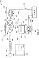
- FIG. 1 illustrates an exemplary phacoemulsification/ vitrectomy system 100 in a functional block diagram to show the components and interfaces fcr a safety critical medical instrument system that may be employed in accordance with an aspect of the present invention.
- a serial communication cable 103 connects GUI host 101 module and instrument host 102 module for the purposes of controlling the surgical instrument host 102 by the GUI host 101.
- GUI host 101 and instrument host 102, as well as any other component of system 100 may be connected wirelessly.
- Instrument host 102 may be considered a computational device in the arrangement shown, but other arrangements are possible.
- An interface communications cable 120 is connected to instrument host 102 module for distributing instrument sensor data 121, and may include distribution of instrument settings and parameters information, to other systems, subsystems and modules within and external to instrument host 102. Although shown connected to the instrument host 102 module, interface communications cable 120 may be connected or realized on any other subsystem (not shown) that could accommodate such an interface device able to distribute the respective data.
- a switch module associated with foot pedal 104 may transmit control signals relating internal physical and virtual switch position information as input to the instrument host 102 over serial communications cable 105 (although footpedal 104 may be connected wirelessly).
- Instrument host 102 may provide a database file system for storing configuration parameter values, programs, and other data saved in a storage device (not shown).
- the database file system may be realized on the GUI host 101 or any other subsystem (not shown) that could accommodate such a file system.
- the phacoemulsification/vitrectomy system 100 has a handpiece 110 that includes a needle and electrical means, typically a piezoelectric crystal, for ultrasonically vibrating the needle.
- the instrument host 102 supplies power on line 111 to a phacoemulsification/vitrectomy handpiece 110.
- An irrigation fluid source 112 can be fluidly coupled to handpiece 110 through line 113.
- the irrigation fluid and ultrasonic power are applied by handpiece 110 to an eye, or affected area or region, indicated diagrammatically by block 114.
- the irrigation source may be routed to eye 114 through a separate pathway independent of the handpiece.
- Aspiration is provided to eye 114 by one or more pumps (not shown), such as a peristaltic pump, via the instrument host 102, through lines 115 and 116.
- pumps such as a peristaltic pump
- a surgeon/operator may select an amplitude of electrical pulses either using the footpedal, via the instrument host, GUI host, and/or by voice command.
- the present system enables aspiration, venting, or reflux functionality in or with the phacoemulsification system and may comprise components including, but not limited to, a flow selector valve, two or more pumps, a reservoir, and a collector, such as a collection bag or a device having similar functionality.
- the collector in the present design collects aspirant from the ocular surgical procedure.
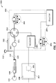
- FIG. 2 illustrates an exemplary surgical cassette system in a functional block diagram that shows the components and interfaces that may be employed in accordance with an aspect of the present design.
- the present design effectively splits the aspiration line from handpiece 110 into at least two separate fluid pathways where one is connected to collector 206 and the other to the air/fluid reservoir 204, which is also connected to collector 206. Splitting the fluid pathways in this way allows one line designated for vacuum regulated aspiration, venting, and/or reflux and the other line designated for peristaltic aspiration, venting, and/or reflux.
- the vacuum regulated aspiration line connects to reservoir 204, wherein fluid may be aspirated, vented, and/or refluxed to or from reservoir 204 through the line.
- the peristaltic line connects directly to the collector and aspirates, vents, and/or refluxes through the aspiration line without requiring a connection to reservoir 204.
- Surgical cassette venting system 200 may include a fluid vacuum sensor 201, flow selector valve 202, reservoir 204, collector 206, and fluid pathways, such as interconnecting surgical tubing, as shown in FIG. 2 .
- the cassette arrangement 250 may include connections to facilitate easy attachment to and removal from the instrument host 102 as well as handpiece 110 and vacuum pump arrangement 207.
- the present design contemplates two pumps, where the surgical cassette arrangement may operate with fluid pathways or other appropriate fluid interconnections interfacing with the two pumps.
- Cassette arrangement 250 is illustrated in FIG. 2 to simply show components that may be enclosed within the cassette.
- the size and shape of cassette 250 is not to scale nor accurately sized, and note that certain components, notably peristaltic pumps 203 and 205, interface with the cassette but in actuality form part of the device which the cassette attaches to. Further, more or fewer components may be included in the cassette than are shown in FIG. 2 depending on the circumstances and implementation of the cassette arrangement 250.
- handpiece 110 is connected to the input side of fluid vacuum sensor 201, typically by fluid pathways such as fluid pathway 220.
- the output side of fluid vacuum sensor 201 is connected to flow selector valve 202 within cassette arrangement 250 via fluid pathway 221.
- the present design may configure flow selector valve 202 to interface between handpiece 110, balanced saline solution (BSS) fluid bottle 112, pump 203, which is shown as a peristaltic pump but may be another type of pump, and reservoir 204.
- BSS balanced saline solution
- pump 203 which is shown as a peristaltic pump but may be another type of pump
- reservoir 204 the system may operate flow selector valve 202 to connect handpiece 110 with BSS fluid bottle 112, reservoir 204 cr with pump 203 based on signals received from instrument host 102 resulting from the surgeon's input to GUI host 101.
- the flow selector valve 202 illustrated in FIG. 2 provides a single input port and may connect port '0' to one of three available ports numbered '1', '2', and '3'.
- the present design is not limited to one flow selector valve, and may be realized using two flow selector valves each having at least two output ports, possibly connected together to provide the functionality described herein.
- a pair of two output port valves may be configured in a daisy chain arrangement, where the output port of a first valve is directly connected to the input port of a second valve.
- the instrument host may operate both valves together to provide three different flow configurations. For example, using two valves, valve one and valve two, valve one may use output port one, which is the supply for valve two.
- Valve two may connect to one of two ports providing two separate paths. When valve one connects its input port to its second output port rather than the output port that directs flow to the second valve, a third path is provided.
- flow selector valve 202 may be or comprise one or more pinch valves.
- the one or more pinch valves may be located along fluid pathway 221 and/or 223, or any other fluid pathway as discussed herein.
- fluid pathway 220 is a single fluid pathway that couples with fluid vacuum sensor 201. From fluid vacuum sensor 201, the single fluid pathway 220 may divide into two fluid pathways, one to collector 206 via pump 203 and one to reservoir 204.
- one or more pinch valves and/or flow selector valve 202 may be located along the fluid pathway between fluid vacuum sensor 201 and collector 206 and/or between fluid vacuum sensor 201 and reservoir 204.
- FIG. 2 While a single flow selector valve 202 is illustrated in FIG. 2 , it is to be understood that this illustration represents a flow selector valve arrangement, including one or more flow selector valves performing the functionality described herein, and is not limited to a single device or a single flow selector valve.
- the present design's fluid vacuum sensor 201 may communicate or signal information to instrument host 102 to provide the amount of vacuum sensed in the handpiece fluid pathway 220.
- Instrument host 102 may determine the actual amount of vacuum present based on the communicated information.
- Fluid vacuum sensor 201 monitors flow into and out of the line, and can be used to determine when flow should be reversed, such as encountering a certain pressure level (e.g. in the presence of an occlusion), and based on values obtained from the fluid vacuum sensor 201, the system may control selector valve 202 and the pumps illustrated. It is to be understood that while components presented in FIG. 2 and other drawings of the present application are not shown connected to other system components, such as instrument host 102, but are in fact connected for the purpose of monitoring and control of the components illustrated.
- fluid vacuum sensor 201 With respect to fluid vacuum sensor 201, emergency conditions such as a dramatic drop or rise in pressure may result in a type of fail-safe operation.
- the present design employs fluid vacuum sensor 201 to monitor the flow conditions and provide signals representing flow conditions to the system such as via instrument host 102 for the purpose of controlling components shown including but not limited to flow selector valve 202 and the pumps shown.
- FIG. 2 Multiple aspiration and ventilation options are available in the design of FIG. 2 .
- the selector valve 202 connects handpiece 110 with BSS bottle 112
- the present design allows for venting of fluid from BSS bottle 112 to eye 114 as indicated by directional flow arrow 'Z' 236 and arrow 'A' 222 in FIG. 2 .
- the present design may allow for aspiration from eye 114 directly to collector 206 as indicated by flow indicated in the directions of 'X' 238, arrow B 242, and arrow E at 232 as illustrated in FIG. 2 . Reversing direction of pump 203 can result in venting.
- venting is shown from BSS bottle 112
- venting and/or irrigation is not represented in FIG. 2 via the pumps.
- the present design may allow for venting and/or reflux using the pumps associated with the cassette where the arrows in FIG. 2 are reversed; for example, indicating pump 203 is reversed or operates in a counter-clockwise direction.
- the design may effectively split the aspiration line from the handpiece into two distinct lines, one arranged for peristaltic operation and the second line arranged for vacuum regulated operation via an air/fluid reservoir.
- Reservoir 204 may contain air in section 211 and fluid in section 212.
- Surgical cassette system 200 may connect reservoir 204 with collector 206 using fluid pathways, such as surgical tubing or similar items.
- pump 205 may operate in a clockwise direction in the direction of arrow 228 to remove fluid from the reservoir 204 through fluid pathway 227 and deliver the fluid to collector 206 using fluid pathway 229.
- the present design illustrates a peristaltic pump as pump 205, a component within instrument host 102, but other types of pumps may be employed. This configuration may enable the surgical cassette 200 to remove unwanted fluid and/or material from reservoir 204.
- the fluid pathways or flow segments of surgical cassette system 200 may include the fluid connections, for example flexible tubing, between each component represented with solid lines in FIG. 2 .
- Vacuum pump arrangement 207 is typically connected with instrument host 102, and may be connected with reservoir 204 via fluid pathway or flow segment 230.
- vacuum pump arrangement 207 includes a pump 208, such as a venturi pump and an optional pressure regulator 209 (and valve (not shown)), but other configurations are possible.
- vacuum pump arrangement 207 may operate to remove air from the top of reservoir 204 and deliver the air to atmosphere (not shown). Removal of air from reservoir 204 in this manner may reduce the pressure within the reservoir, which reduces the pressure in the attached fluid pathway 226, to a level less than the pressure within eye 114.
- a lower reservoir pressure connected through flow selector valve 202 may cause fluid to move from the eye, thereby providing aspiration.
- the vacuum pump arrangement 207 and reservoir 204 can be used to control fluid flow into and out of reservoir 204.
- the optional pressure regulator 209 may operate to add air to the top of reservoir 204 which in turn increases pressure and may force the air-fluid boundary 213 to move downward. Adding air into reservoir 204 in this manner may increase the air pressure within the reservoir, which increases the pressure in the attached fluid aspiration line 226 to a level greater than the pressure within eye 114. A higher reservoir pressure connected through flow selector valve 203 may cause fluid to move toward eye 114, thereby providing venting or reflux.
- An alternate method of creating positive pressure in reservoir 204 is running pump 205 in a counter-clockwise direction. Running pump 205 in a counter-clockwise direction will increase the amount of air in section 211 in reservoir 204.
- reservoir 204 causes more fluid flow and potentially more reflux from reservoir 204 to handpiece 110. If the lines from the reservoir 204 are plugged or otherwise occluded, providing pressure to reservoir 204 can result in venting and/or reflux. Venting in this context results in the release of pressure. Reflux occurs when a pump is reversed sending fluid in the opposite direction of normal flow (e.g. toward the eye). In a reflux condition, the surgeon can control the amount of fluid flowing back through the fluid pathways and components.
- the present design may involve peristaltic operation, aspirating fluid from eye 114 to collector 206 illustrated in FIG. 2 , or venting fluid to the eye 114 to reduce the amount of pressure in the aspiration line (where such venting is only shown from BSS bottle 112 in FIG. 2 ).
- Peristaltic pumping is generally understood to those skilled in the art, and many current machines employ peristaltic and/or venturi pumps as the vacuum or pressure sources.
- a peristaltic pump has fluid flowing through a flexible tube and a circular rotor with a number of rollers attached to the periphery of the circular rotor. As the rotor turns, fluid is forced through the tube.
- Venturi pumping or aspiration or aspirator pumping, produces the vacuum using the venturi effect by providing fluid through a narrowing tube. Because of the narrowing of the tube, the speed at which the fluid travels through the tube increases and the fluid pressure decreases (the "Venturi effect"). As may be appreciated, operating pumps in one direction or another can change the pressure and the operation of the associated device, such as the operation of the cassette in the present design.
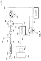
- FIG. 3 is a functional block diagram illustrating a surgical cassette system configured for venting using a balanced saline solution (BSS) bottle in accordance with an aspect of the present design.
- BSS balanced saline solution
- the present design may allow for venting of fluid to eye 114 directly from BSS bottle 112 and/or the line between flow selector valve 202 and BSS bottle 112, where fluid from BSS bottle 112 and/or the line flows toward and through flow selector valve 202.
- the fluid flow continues to flow toward and through flow selector valve 202 in the direction indicated by arrow 321.
- instrument host 102 may signal flow selector valve 202 to connect port '0' to port '1'.
- the present design aspirates fluid from eye 114 to collector 206 following the path formed by connecting fluid pathway 420 from the handpiece to fluid vacuum sensor 201, continuing through fluid pathway 421 toward the flow selector valve 202 where a fluid line is connected from flow selector valve 202 to pump 203 and moving fluid in the direction shown by the arrow above fluid pathway 422.
- Clockwise pump operation shown by arrow 423 forces fluid into fluid pathway 425 in direction 424 toward collector 206.
- the surgeon may stop the flow of fluid into the eye by stopping pump 203. When pump 203 is stopped, the rollers within the peristaltic pump stop moving and fluid through this path ceases to move or flow.
- FIG. 5 illustrates a surgical cassette system 500 configured for venting and reflux operation.
- the present design may configure flow selector valve 202 to connect handpiece 110 to pump 203 from port '3' to port '0'.
- the present design may vent fluid through fluid pathway 525 in direction of flow arrows at 524, 523, 522, and 521 and ultimately to fluid pathway 220. Note that in both FIGS. 4 and 5 , flow selector valve 202 neither operates to take fluid from nor output fluid to reservoir 204.
- the system can stop the inflow of fluid from fluid pathway 525 to the eye by stopping pump 203 or closing flow selector valve 202, or both.
- the internal volume of fluid pathway 525 has sufficient fluid volume to provide venting and/or reflux.
- the present design may alternately employ vacuum pump arrangement 207 to aspirate fluid from eye 114 to reservoir 204 as illustrated in FIG. 6 , or applying pressure thus forcing fluid from reservoir 204 through selector valve 202 and irrigating eye 114 as illustrated in FIG. 7 .
- FIG. 6 is a functional block diagram illustrating the system configured for vacuum pump arrangement 207 aspiration operation where the present design may operate either in a normal venturi aspiration mode to create a vacuum at fluid pathway 626.
- flow selector valve 202 connects handpiece 110 with reservoir 204 from port 2' to port '0'.
- pump 203 is not in use and typically not operating.
- Vacuum pump arrangement 207 may operate to allow pressure to be removed from reservoir 204 either by venting to atmosphere or drawing a vacuum. Removing or reducing pressure using vacuum pump arrangement 207 may move air-fluid boundary 213 upward at 645 to aspirate fluid from eye 114 to reservoir 204.
- vacuum pump arrangement 207 may include or be attached to a venturi pump or pumping device.
- the fluid path from eye 114 to reservoir 204 follows the direction indicated by the arrows above fluid passageway 621 and to the right of fluid passageway 626.
- pressure regulator 209 may be used to increase the pressure in reservoir 204 to cause fluid to flow through fluid pathway 626 toward handpiece 110 via flow selector valve 202.
- FIG. 7 is a functional block diagram illustrating a surgical cassette system 700 configured for venting and/or reflux operation in accordance with an aspect of the present invention.
- the present design may configure flow selector valve 202 to connect handpiece 11C with reservoir 204 from port '2' to port '0'.
- Vacuum pump arrangement 207 may operate to provide pressure to reservoir 204 via pressure regulator 209. Applying or increasing pressure using pressure regular 209 of vacuum pump arrangement 207 may move air-fluid boundary 213 downward in the direction of 745 causing fluid to flow from reservoir 204 and/or fluid pathway 726 to eye 114.
- the present design surgical cassette system provides for aspiration, venting, and/or reflux using pumping operations.
- a plurality of pumps are typically employed, including a first pump and a second pump, where a first pump may be pump 203, shown as a peristaltic pump in FIG. 2 , and pump 208, representing a venturi pump in certain embodiments shown herein.
- the instrument host 102 may provide a signal to position or switch flow selector valve 202 for desired peristaltic or vacuum regulated operation.
- Aspiration, venting, and/or reflux may be controlled in various ways, including but not limited to switching offered to the surgeon on the instrument host 102, switching via a switch such as one provided on handpiece 110 or via a footswitch, or via automatic or semi-automatic operation, wherein pressure is sensed at some point, such as coming from the handpiece to the instrument host at sensor 201 or separately sensed by a sensor placed in the ocular region with pressure signals being provided to the instrument host 102.
- automatic or semi-automatic operation entails sensing a drop or rise in pressure and either aspirating fluid to or venting fluid from the ocular region or eye 114.
- surgeon or other personnel are provided with the ability to run the pumps in any available direction, such as for cleaning purposes.
- Other pumping states may be provided as discussed herein and based on the desires of personnel performing the surgical procedure. For example, in the case of the surgeon desiring aspiration operation as shown in FIG. 6 in all circumstances as opposed to aspiration as shown in FIG. 4 , the surgeon may enable settings or the instrument host may provide for the surgeon to select such operation. Additionally, if the surgeon believes venturi pumping or vacuum regulator operation should be employed wherever possible, she may select that operation from a component with connection to the instrument host. Other configurations may be provided, including limiting ocular pressure within a desired range, and so forth.
- a valve may be located between pump 203 and flow selector valve 202 or between pump 203 and handpiece 110 in the design, such as in the design of FIG. 3 , to build a bolus of fluid or build pressure between the valve and pump 203.
- a valve can thereby create positive pressure when pump 203, such as a peristaltic pump, reverses direction of flow and provides pressure to the valve. This positive pressure can be released by opening the valve thereby venting the system.
Description
- The present invention relates generally to the field of surgery, and more specifically to managing pressure within the eye by controlling the inflow of fluid using a specialized cassette during ophthalmic procedures such as the removal of a cataract.
- Phacoemulsification surgery has been successfully employed in the treatment of certain ocular problems, such as cataract surgery, including removal of a cataract-damaged lens and implanting an artificial intraocular lens. Phacoemulsification surgery typically involves removal of the cataract-damaged lens and may utilize a small incision at the edge of the cornea. Through the small incision, the surgeon then creates an opening in the capsule, i.e. membrane that encapsulates the lens.
- Next, the surgeon may insert an ultrasonic probe, incorporated within the phacoemulsification handpiece, through the opening in the cornea and capsule accessing the damaged lens. The handpiece's ultrasonic actuated tip emulsifies the damaged lens sufficient to be evacuated by the handpiece. After the damaged natural lens is completely removed, the handpiece tip is withdrawn from the eye. The surgeon may now implant an intraocular lens into the space made available in the capsule.
- While performing phacoemulsification surgical techniques, such as lens removal, it is necessary for the surgeon to be able to stop the flow of fluid into the phaco handpiece tip and into the ocular cavity. Stopping the flow generally entails reversing the flow of fluid, such as by reversing pump operation. One example of a need to stop flow is encountering an occlusion during emulsification of the damaged lens, wherein the tip of the phaco handpiece may become partially blocked or occluded. As the tip becomes further blocked or completely occluded, the vacuum in the aspiration line of the phaco handpiece builds proportionally. When the tip becomes unoccluded, due to removal or movement of the occlusion, the handpiece begins aspirating fluid to equalize the resulting pressure differential between the eye and the aspiration line. In order to stop the flow, the aspiration line can be vented to ambient pressure, the pump can be stopped, a pressure source can be reversed, such as a reversible peristaltic pump or an irrigation bottle or via an other mechanism known in the art. Flow may be stopped by the concept of reflux. Reflux occurs when pump pressure is reversed, thereby building pressure, and a positive pressure regulator is employed such that fluid flows backward once pressure is released.
- When aspirating, venting, and/or refluxing, the present design typically employs two or more pumps. Any pump known in the art may be used with the present invention, including, but not limited to, peristaltic, venturi (wherein fluid flowing through a narrowing pipe produces vacuum as a result of the "Venturi effect"), and/or other flow or vacuum based pumps. In general, designs that operate efficiently in this dual-pump environment, wherein aspiration, venting, reflux, and/or irrigation may be initiated and terminated intermittently, can provide significant benefits in an operating room environment.
- Many existing cassettes operate together with a single vacuum source, such as a single type of pump. When the phacoemulsification device has dual pump capability, it typically employs a specific replaceable cassette that enables dual pump operation and can be changed after a surgical procedure. A dual pump cassette exhibiting an efficient venting mechanism that can aspirate or irrigate fluid is highly beneficial.
- Providing vacuum from different types of pumps or different types of devices enabling precision aspiration and irrigation can be desirable in an operating room situation. While certain multiple pump type cassettes have previously been offered, reliability in venting, aspirating and operating these cassettes can at times be imperfect, particularly in precise operating environments. Further, certain existing designs simply transfer all fluids into a reservoir, thereby rapidly filling up the reservoir, which is undesirable. If the reservoir is filled too rapidly or too frequently during a procedure, valuable time can be lost while the reservoir is drained. Additionally, previous designs have offered arrangements wherein both venting and aspiration are performed in a single line, such as a line connected to the reservoir. Separation of venting and aspiration functions can be advantageous and can provide improved performance over a single line used to perform both functions.
- Also, certain previous designs include vent valves or other mechanisms which are sometimes undesirable. It would be beneficial to offer a dual pump cassette that employs minimal components or components that efficiently perform the aspiration and irrigation tasks required in the ocular surgical environment.
-
US 2008/0112828 relates to methods, devices and systems for laser eye surgery generally making use of a console that is to interchangeably accept multiple types of eye treatment cassettes. The cassettes are to enable one or both of displacement-based or vacuum-based aspiration. -
US 5,830,176 relates to varying the flow rate and/or the fluid pressure heading through a surgical instrument by selecting which of a plurality of fluid lines will supply fluid through the infusion line of the instrument. The fluid lines connect with supply ports of a common connector that has a common discharge port in fluid connection with the infusion line. -
US 2005/118048 relates to a cartridge or cassette adapted to be attached to an apparatus for controlling the flow of fluid to and from a surgical handpiece. The cassette includes irrigation and aspiration fluid-flow paths. - The present invention provides a surgical cassette arrangement as recited in the claims.
- Also disclosed, but not falling within the scope of the claimed invention is a method for selectively venting and aspirating fluid to and from a handpiece employed in an ocular surgical procedure. The method includes providing a first pumping operation and a second pumping operation and selecting operation between the first pumping operation and the second pumping operation using a flow selector valve. The first pumping operation controls fluid flow to and from an eye using a first pump fluidly connecting the flow selector valve to a first fluid pathway via a first port in the selector valve. The second pumping operation controls fluid flow to and from the eye by varying pressure inside a reservoir fluidly connected to the flow selector valve via a second fluid pathway connected to a second port in the flow selector valve.
- These and other advantages of the present invention will become apparent to those skilled in the art from the following detailed description of the invention and the accompanying drawings.
- The present invention is illustrated by way of example, and not by way of limitation, in the figures of the accompanying drawings in which:
-
FIG. 1 illustrates an exemplary phacoemulsification/ vitrectomy irrigation/aspiration system in a functional block diagram to show the components and interfaces for a safety critical medical instrument system that may be employed in accordance with an aspect of the present invention; -
FIG. 2 is a functional block diagram of an exemplary surgical cassette venting system in accordance with the present design; -
FIG. 3 is a functional block diagram illustrating a surgical cassette venting system configured for venting to a BSS (irrigation) bottle in accordance with an aspect of the present design; -
FIG. 4 is a functional block diagram illustrating a surgical cassette venting system configured for peristaltic aspiration operation in accordance with the present design; -
FIG. 5 is a functional block diagram illustrating a surgical cassette venting system configured for peristaltic venting operation in accordance with the present design; -
FIG. 6 is a functional block diagram illustrating a surgical cassette venting system configured for vacuum regulator aspiration operation in accordance with the present design; and -
FIG. 7 is a functional block diagram illustrating a surgical cassette venting system configured for vacuum regulator venting operation in accordance with the present design. - The present design is directed to controlling pressure within an eye during an ocular procedure that involves either aspiration or irrigation of the eye via a handpiece connected to a phacoemulsification system. The present arrangement may include a pump component configured to provide either aspiration or venting for purposes of pressure control when connected to the phacoemulsification system. For example, the phacoemulsification system may provide for peristaltic aspiration, where a surgeon performing an ocular surgery may balance or equalize a pressure differential between the eye and the aspiration line by venting in the situation where the handpiece tip becomes occluded. During peristaltic aspiration with no occlusion, the system moves fluid from the eye to a collector, where the collector may include a device such as a collection bag. In order to vent or reflux fluid into the eye, the present design reverses the pumping direction or vents to atmospheric pressure, and reversing pumping direction typically occurs at a very rapid rate.
- The system may include a vacuum pump arrangement configured to provide either aspiration or venting for purposes of accurate pressure control within the eye. For example, the system can provide vacuum regulated venting, where a surgeon performing an ocular surgical procedure may need to balance or equalize a pressure differential due to an occlusion. During vacuum regulator venting, the system moves fluid from the holding tank or reservoir to the eye by increasing the pressure within or associated with the reservoir. In order to aspirate the eye, the vacuum regulator reverses the fluid flow, removing fluid from the eye by reducing the pressure within the reservoir.
- The present design includes a surgical cassette arrangement configured for use with a medical instrument system, such as a phacoemulsification system, wherein the system is configured with two or more pumps to control the flow of fluid into the phaco handpiece tip and ocular region, where the cassette arrangement supports both reflux, venting and aspiration functionality. The present design provides a flow selector valve configured to provide multiple pathways for aspiration, venting, and/or reflux. The result is a design that operates better in certain common circumstances than designs previously available.
- The present design is intended to provide a reliable, noninvasive, and efficient cassette venting apparatus and method for use in a medical instrument system for use in efficiently controlling the flow of fluids into and out of an eye during an ocular procedure.
- Note that as used herein, the phrase "fluidly connected" or "fluidly connectable" is intended to be employed as broadly as possible, including but not limited to meaning, when used in connection with two components, that fluid may pass between the two components even if they are remotely located and/or connected via intermediate components or connectors, either operational or non-operational. Thus as used herein, "fluidly connected" or "fluidly connectable" indicates fluid can flow or is capable of flowing between components, even if pumping components or other intermediate components facilitating fluid flow are not operating or are restricting flow.
- While the present design may be used in various environments and applications, it will be discussed herein with a particular emphasis on an environment where a surgeon or health care practitioner performs. For example, one embodiment of the present design is in or with an ocular surgical system that comprises an independent graphical user interface (GUI) host module, an instrument host module, a GUI device, and a controller module, such as a foot switch, to control the surgical system.
-
FIG. 1 illustrates an exemplary phacoemulsification/vitrectomy system 100 in a functional block diagram to show the components and interfaces fcr a safety critical medical instrument system that may be employed in accordance with an aspect of the present invention. Aserial communication cable 103 connectsGUI host 101 module andinstrument host 102 module for the purposes of controlling thesurgical instrument host 102 by theGUI host 101.GUI host 101 andinstrument host 102, as well as any other component ofsystem 100 may be connected wirelessly.Instrument host 102 may be considered a computational device in the arrangement shown, but other arrangements are possible. Aninterface communications cable 120 is connected toinstrument host 102 module for distributinginstrument sensor data 121, and may include distribution of instrument settings and parameters information, to other systems, subsystems and modules within and external toinstrument host 102. Although shown connected to theinstrument host 102 module,interface communications cable 120 may be connected or realized on any other subsystem (not shown) that could accommodate such an interface device able to distribute the respective data. - A switch module associated with
foot pedal 104 may transmit control signals relating internal physical and virtual switch position information as input to theinstrument host 102 over serial communications cable 105 (althoughfootpedal 104 may be connected wirelessly).Instrument host 102 may provide a database file system for storing configuration parameter values, programs, and other data saved in a storage device (not shown). In addition, the database file system may be realized on theGUI host 101 or any other subsystem (not shown) that could accommodate such a file system. - The phacoemulsification/
vitrectomy system 100 has ahandpiece 110 that includes a needle and electrical means, typically a piezoelectric crystal, for ultrasonically vibrating the needle. Theinstrument host 102 supplies power online 111 to a phacoemulsification/vitrectomy handpiece 110. Anirrigation fluid source 112 can be fluidly coupled tohandpiece 110 throughline 113. The irrigation fluid and ultrasonic power are applied byhandpiece 110 to an eye, or affected area or region, indicated diagrammatically byblock 114. Alternatively, the irrigation source may be routed to eye 114 through a separate pathway independent of the handpiece. Aspiration is provided to eye 114 by one or more pumps (not shown), such as a peristaltic pump, via theinstrument host 102, throughlines - In combination with
phacoemulsification system 100, the present system enables aspiration, venting, or reflux functionality in or with the phacoemulsification system and may comprise components including, but not limited to, a flow selector valve, two or more pumps, a reservoir, and a collector, such as a collection bag or a device having similar functionality. The collector in the present design collects aspirant from the ocular surgical procedure. -
FIG. 2 illustrates an exemplary surgical cassette system in a functional block diagram that shows the components and interfaces that may be employed in accordance with an aspect of the present design. - The present design effectively splits the aspiration line from
handpiece 110 into at least two separate fluid pathways where one is connected tocollector 206 and the other to the air/fluid reservoir 204, which is also connected tocollector 206. Splitting the fluid pathways in this way allows one line designated for vacuum regulated aspiration, venting, and/or reflux and the other line designated for peristaltic aspiration, venting, and/or reflux. The vacuum regulated aspiration line connects toreservoir 204, wherein fluid may be aspirated, vented, and/or refluxed to or fromreservoir 204 through the line. The peristaltic line connects directly to the collector and aspirates, vents, and/or refluxes through the aspiration line without requiring a connection toreservoir 204. - Surgical
cassette venting system 200 may include afluid vacuum sensor 201,flow selector valve 202,reservoir 204,collector 206, and fluid pathways, such as interconnecting surgical tubing, as shown inFIG. 2 . Thecassette arrangement 250 may include connections to facilitate easy attachment to and removal from theinstrument host 102 as well ashandpiece 110 andvacuum pump arrangement 207. The present design contemplates two pumps, where the surgical cassette arrangement may operate with fluid pathways or other appropriate fluid interconnections interfacing with the two pumps. -
Cassette arrangement 250 is illustrated inFIG. 2 to simply show components that may be enclosed within the cassette. The size and shape ofcassette 250 is not to scale nor accurately sized, and note that certain components, notablyperistaltic pumps FIG. 2 depending on the circumstances and implementation of thecassette arrangement 250. - Referring to
FIG. 2 ,handpiece 110 is connected to the input side offluid vacuum sensor 201, typically by fluid pathways such asfluid pathway 220. The output side offluid vacuum sensor 201 is connected to flowselector valve 202 withincassette arrangement 250 viafluid pathway 221. The present design may configureflow selector valve 202 to interface betweenhandpiece 110, balanced saline solution (BSS)fluid bottle 112, pump 203, which is shown as a peristaltic pump but may be another type of pump, andreservoir 204. In this configuration, the system may operateflow selector valve 202 to connecthandpiece 110 with BSSfluid bottle 112,reservoir 204 cr withpump 203 based on signals received frominstrument host 102 resulting from the surgeon's input toGUI host 101. - The
flow selector valve 202 illustrated inFIG. 2 provides a single input port and may connect port '0' to one of three available ports numbered '1', '2', and '3'. The present design is not limited to one flow selector valve, and may be realized using two flow selector valves each having at least two output ports, possibly connected together to provide the functionality described herein. For example, a pair of two output port valves may be configured in a daisy chain arrangement, where the output port of a first valve is directly connected to the input port of a second valve. The instrument host may operate both valves together to provide three different flow configurations. For example, using two valves, valve one and valve two, valve one may use output port one, which is the supply for valve two. Valve two may connect to one of two ports providing two separate paths. When valve one connects its input port to its second output port rather than the output port that directs flow to the second valve, a third path is provided. - It is also envisioned that
flow selector valve 202 may be or comprise one or more pinch valves. The one or more pinch valves may be located alongfluid pathway 221 and/or 223, or any other fluid pathway as discussed herein. Further, there may be one or more fluid pathways coupled withhandpiece 110 and extending to various components ofcassette arrangement 250, including a first fluid pathway fromfluid vacuum sensor 201 tocollector 206 viapump 203 and/or a second fluid pathway toreservoir 204. In another embodiment,fluid pathway 220 is a single fluid pathway that couples withfluid vacuum sensor 201. Fromfluid vacuum sensor 201, thesingle fluid pathway 220 may divide into two fluid pathways, one tocollector 206 viapump 203 and one toreservoir 204. Further, one or more pinch valves and/or flowselector valve 202 may be located along the fluid pathway betweenfluid vacuum sensor 201 andcollector 206 and/or betweenfluid vacuum sensor 201 andreservoir 204. - Thus while a single
flow selector valve 202 is illustrated inFIG. 2 , it is to be understood that this illustration represents a flow selector valve arrangement, including one or more flow selector valves performing the functionality described herein, and is not limited to a single device or a single flow selector valve. - The present design's
fluid vacuum sensor 201, for example a strain gauge or other suitable component, may communicate or signal information toinstrument host 102 to provide the amount of vacuum sensed in thehandpiece fluid pathway 220.Instrument host 102 may determine the actual amount of vacuum present based on the communicated information. -
Fluid vacuum sensor 201 monitors flow into and out of the line, and can be used to determine when flow should be reversed, such as encountering a certain pressure level (e.g. in the presence of an occlusion), and based on values obtained from thefluid vacuum sensor 201, the system may controlselector valve 202 and the pumps illustrated. It is to be understood that while components presented inFIG. 2 and other drawings of the present application are not shown connected to other system components, such asinstrument host 102, but are in fact connected for the purpose of monitoring and control of the components illustrated. - With respect to
fluid vacuum sensor 201, emergency conditions such as a dramatic drop or rise in pressure may result in a type of fail-safe operation. The present design employsfluid vacuum sensor 201 to monitor the flow conditions and provide signals representing flow conditions to the system such as viainstrument host 102 for the purpose of controlling components shown including but not limited to flowselector valve 202 and the pumps shown. - Multiple aspiration and ventilation options are available in the design of
FIG. 2 . In the arrangement where theselector valve 202 connectshandpiece 110 withBSS bottle 112, the present design allows for venting of fluid fromBSS bottle 112 to eye 114 as indicated by directional flow arrow 'Z' 236 and arrow 'A' 222 inFIG. 2 . In the arrangement where theflow selector valve 202 connectshandpiece 110 withperistaltic pump 203, the present design may allow for aspiration fromeye 114 directly tocollector 206 as indicated by flow indicated in the directions of 'X' 238,arrow B 242, and arrow E at 232 as illustrated inFIG. 2 . Reversing direction ofpump 203 can result in venting. - In the arrangement where the cassette system
flow selector valve 202 connectshandpiece 110 withreservoir 204, the present design allows for aspiration fromeye 114 directly toreservoir 204 as indicated by directional flow arrow 'X' 238, andarrow C 240 inFIG. 2 . Arrows/directions Arrow 224 indicates the direction of operation forperistaltic pump 203 where fluid originating athandpiece 110 is pumped throughline 223 towardline 225 during aspiration. Arrows/directions - Although venting is shown from
BSS bottle 112, venting and/or irrigation is not represented inFIG. 2 via the pumps. However, the present design may allow for venting and/or reflux using the pumps associated with the cassette where the arrows inFIG. 2 are reversed; for example, indicatingpump 203 is reversed or operates in a counter-clockwise direction. In this arrangement, the design may effectively split the aspiration line from the handpiece into two distinct lines, one arranged for peristaltic operation and the second line arranged for vacuum regulated operation via an air/fluid reservoir. -
Reservoir 204 may contain air insection 211 and fluid insection 212.Surgical cassette system 200 may connectreservoir 204 withcollector 206 using fluid pathways, such as surgical tubing or similar items. In this arrangement, pump 205 may operate in a clockwise direction in the direction ofarrow 228 to remove fluid from thereservoir 204 throughfluid pathway 227 and deliver the fluid tocollector 206 usingfluid pathway 229. The present design illustrates a peristaltic pump aspump 205, a component withininstrument host 102, but other types of pumps may be employed. This configuration may enable thesurgical cassette 200 to remove unwanted fluid and/or material fromreservoir 204. - The fluid pathways or flow segments of
surgical cassette system 200 may include the fluid connections, for example flexible tubing, between each component represented with solid lines inFIG. 2 . -
Vacuum pump arrangement 207 is typically connected withinstrument host 102, and may be connected withreservoir 204 via fluid pathway orflow segment 230. In the configuration shown,vacuum pump arrangement 207 includes apump 208, such as a venturi pump and an optional pressure regulator 209 (and valve (not shown)), but other configurations are possible. In this arrangement,vacuum pump arrangement 207 may operate to remove air from the top ofreservoir 204 and deliver the air to atmosphere (not shown). Removal of air fromreservoir 204 in this manner may reduce the pressure within the reservoir, which reduces the pressure in the attachedfluid pathway 226, to a level less than the pressure withineye 114. A lower reservoir pressure connected throughflow selector valve 202 may cause fluid to move from the eye, thereby providing aspiration. Thevacuum pump arrangement 207 andreservoir 204 can be used to control fluid flow into and out ofreservoir 204. - The
optional pressure regulator 209 may operate to add air to the top ofreservoir 204 which in turn increases pressure and may force the air-fluid boundary 213 to move downward. Adding air intoreservoir 204 in this manner may increase the air pressure within the reservoir, which increases the pressure in the attachedfluid aspiration line 226 to a level greater than the pressure withineye 114. A higher reservoir pressure connected throughflow selector valve 203 may cause fluid to move towardeye 114, thereby providing venting or reflux. - An alternate method of creating positive pressure in
reservoir 204 is runningpump 205 in a counter-clockwise direction. Runningpump 205 in a counter-clockwise direction will increase the amount of air insection 211 inreservoir 204. - It is to be noted that higher pressure in
reservoir 204 causes more fluid flow and potentially more reflux fromreservoir 204 tohandpiece 110. If the lines from thereservoir 204 are plugged or otherwise occluded, providing pressure toreservoir 204 can result in venting and/or reflux. Venting in this context results in the release of pressure. Reflux occurs when a pump is reversed sending fluid in the opposite direction of normal flow (e.g. toward the eye). In a reflux condition, the surgeon can control the amount of fluid flowing back through the fluid pathways and components. - The present design may involve peristaltic operation, aspirating fluid from
eye 114 tocollector 206 illustrated inFIG. 2 , or venting fluid to theeye 114 to reduce the amount of pressure in the aspiration line (where such venting is only shown fromBSS bottle 112 inFIG. 2 ). Peristaltic pumping is generally understood to those skilled in the art, and many current machines employ peristaltic and/or venturi pumps as the vacuum or pressure sources. Generally, a peristaltic pump has fluid flowing through a flexible tube and a circular rotor with a number of rollers attached to the periphery of the circular rotor. As the rotor turns, fluid is forced through the tube. Venturi pumping, or aspiration or aspirator pumping, produces the vacuum using the venturi effect by providing fluid through a narrowing tube. Because of the narrowing of the tube, the speed at which the fluid travels through the tube increases and the fluid pressure decreases (the "Venturi effect"). As may be appreciated, operating pumps in one direction or another can change the pressure and the operation of the associated device, such as the operation of the cassette in the present design. -
FIG. 3 is a functional block diagram illustrating a surgical cassette system configured for venting using a balanced saline solution (BSS) bottle in accordance with an aspect of the present design. - In the arrangement where the
flow selector valve 202 connectshandpiece 110 withBSS bottle 112, the present design may allow for venting of fluid to eye 114 directly fromBSS bottle 112 and/or the line betweenflow selector valve 202 andBSS bottle 112, where fluid fromBSS bottle 112 and/or the line flows toward and throughflow selector valve 202. The fluid flow continues to flow toward and throughflow selector valve 202 in the direction indicated byarrow 321. In order to vent fromBSS bottle 112,instrument host 102 may signalflow selector valve 202 to connect port '0' to port '1'. When theflow selector valve 202 switches to position '1,' fluid may flow fromBSS bottle 112 and/or the line betweenBSS bottle 112 and flowselector valve 202 to handpiece 110 as indicated bydirectional arrows FIG. 3 . During fluid venting frombottle 112 and/or the line betweenBSS bottle 112 and flowselector valve 202, the present design may arrange the bottle position at an elevated height relative to theeye 114, thus realizing a positive pressure source. -
FIG. 4 is a functional block diagram illustrating asurgical cassette system 400 configured for normal peristaltic aspiration. The present design may configureflow selector valve 202 to connecthandpiece 110 to pump 203 and may operateselector valve 202 to connectfluid pathway 421 at port '0' tofluid pathway 422 at port '3' offlow selector valve 202. In this aspiration configuration,reservoir 204 is not employed. Aspump 203 operates in a clockwise direction to pump fluid in the direction shown byarrow 424, the present design aspirates fluid fromeye 114 tocollector 206 following the path formed by connectingfluid pathway 420 from the handpiece tofluid vacuum sensor 201, continuing throughfluid pathway 421 toward theflow selector valve 202 where a fluid line is connected fromflow selector valve 202 to pump 203 and moving fluid in the direction shown by the arrow abovefluid pathway 422. Clockwise pump operation shown byarrow 423 forces fluid intofluid pathway 425 indirection 424 towardcollector 206. During an ocular procedure, the surgeon may stop the flow of fluid into the eye by stoppingpump 203. Whenpump 203 is stopped, the rollers within the peristaltic pump stop moving and fluid through this path ceases to move or flow. -
FIG. 5 illustrates asurgical cassette system 500 configured for venting and reflux operation. The present design may configureflow selector valve 202 to connecthandpiece 110 to pump 203 from port '3' to port '0'. As thepump 203 operates in a counter-clockwise direction as shown byarrow 523, the present design may vent fluid throughfluid pathway 525 in direction of flow arrows at 524, 523, 522, and 521 and ultimately tofluid pathway 220. Note that in bothFIGS. 4 and5 ,flow selector valve 202 neither operates to take fluid from nor output fluid toreservoir 204. - In the configuration of
FIG. 5 , the system can stop the inflow of fluid fromfluid pathway 525 to the eye by stoppingpump 203 or closingflow selector valve 202, or both. The internal volume offluid pathway 525 has sufficient fluid volume to provide venting and/or reflux. - The present design may alternately employ
vacuum pump arrangement 207 to aspirate fluid fromeye 114 toreservoir 204 as illustrated inFIG. 6 , or applying pressure thus forcing fluid fromreservoir 204 throughselector valve 202 and irrigatingeye 114 as illustrated inFIG. 7 . -
FIG. 6 is a functional block diagram illustrating the system configured forvacuum pump arrangement 207 aspiration operation where the present design may operate either in a normal venturi aspiration mode to create a vacuum atfluid pathway 626. Again,flow selector valve 202 connectshandpiece 110 withreservoir 204 from port 2' to port '0'. In this aspiration configuration, pump 203 is not in use and typically not operating.Vacuum pump arrangement 207 may operate to allow pressure to be removed fromreservoir 204 either by venting to atmosphere or drawing a vacuum. Removing or reducing pressure usingvacuum pump arrangement 207 may move air-fluid boundary 213 upward at 645 to aspirate fluid fromeye 114 toreservoir 204. Again,vacuum pump arrangement 207 may include or be attached to a venturi pump or pumping device. The fluid path fromeye 114 toreservoir 204 follows the direction indicated by the arrows abovefluid passageway 621 and to the right offluid passageway 626. Optionally, to vent and/or reflux,pressure regulator 209 may be used to increase the pressure inreservoir 204 to cause fluid to flow throughfluid pathway 626 towardhandpiece 110 viaflow selector valve 202. -
FIG. 7 is a functional block diagram illustrating asurgical cassette system 700 configured for venting and/or reflux operation in accordance with an aspect of the present invention. The present design may configureflow selector valve 202 to connect handpiece 11C withreservoir 204 from port '2' to port '0'.Vacuum pump arrangement 207 may operate to provide pressure toreservoir 204 viapressure regulator 209. Applying or increasing pressure using pressure regular 209 ofvacuum pump arrangement 207 may move air-fluid boundary 213 downward in the direction of 745 causing fluid to flow fromreservoir 204 and/orfluid pathway 726 toeye 114. - In sum, the present design surgical cassette system provides for aspiration, venting, and/or reflux using pumping operations. A plurality of pumps are typically employed, including a first pump and a second pump, where a first pump may be pump 203, shown as a peristaltic pump in
FIG. 2 , and pump 208, representing a venturi pump in certain embodiments shown herein. - The
instrument host 102 may provide a signal to position or switchflow selector valve 202 for desired peristaltic or vacuum regulated operation. Aspiration, venting, and/or reflux may be controlled in various ways, including but not limited to switching offered to the surgeon on theinstrument host 102, switching via a switch such as one provided onhandpiece 110 or via a footswitch, or via automatic or semi-automatic operation, wherein pressure is sensed at some point, such as coming from the handpiece to the instrument host atsensor 201 or separately sensed by a sensor placed in the ocular region with pressure signals being provided to theinstrument host 102. In general, automatic or semi-automatic operation entails sensing a drop or rise in pressure and either aspirating fluid to or venting fluid from the ocular region oreye 114. In any circumstance, the surgeon or other personnel are provided with the ability to run the pumps in any available direction, such as for cleaning purposes. - Other pumping states may be provided as discussed herein and based on the desires of personnel performing the surgical procedure. For example, in the case of the surgeon desiring aspiration operation as shown in
FIG. 6 in all circumstances as opposed to aspiration as shown inFIG. 4 , the surgeon may enable settings or the instrument host may provide for the surgeon to select such operation. Additionally, if the surgeon believes venturi pumping or vacuum regulator operation should be employed wherever possible, she may select that operation from a component with connection to the instrument host. Other configurations may be provided, including limiting ocular pressure within a desired range, and so forth. - Certain additional functionality or components may be provided in the current design. For example, a valve (not shown) may be located between
pump 203 and flowselector valve 202 or betweenpump 203 andhandpiece 110 in the design, such as in the design ofFIG. 3 , to build a bolus of fluid or build pressure between the valve and pump 203. Such a valve can thereby create positive pressure whenpump 203, such as a peristaltic pump, reverses direction of flow and provides pressure to the valve. This positive pressure can be released by opening the valve thereby venting the system.
Claims (11)
- A surgical cassette arrangement (250) comprising:a flow selector valve (202) configured to operate with a handpiece (110) to selectively irrigate and aspirate fluid with respect to an ocular region, the flow selector valve (202) comprising a first port fluidly connectable to the handpiece (110);a reservoir (204) fluidly connected to a second port of the selector valve (202) via a first flow segment and configured to receive fluid from the selector valve (202); anda collector (206) configured to receive fluid; characterised by:the flow selector valve (202) having a third port, wherein the collector (206) is fluidly connected to the third port of the flow selector valve (202) via a second flow segment (225); andthe collector (206) is configured to receive fluid from the flow selector valve (202) and from the reservoir (204);wherein the flow selector valve (202) selectively controls irrigation and aspiration flow to and from the handpiece (110) and ocular region.
- The surgical cassette arrangement (250) of claim 1, further comprising a first pump (203), wherein the first pump (203) is coupled with the flow selector valve (202) and the collector (206); and configured to distribute fluid through the flow selector valve (202) to the collector (206).
- The surgical cassette arrangement (250) of claim 2, further comprising a second pump (205), wherein the second pump (205) is coupled with the reservoir (204) and configured to distribute fluid from the reservoir (204) to the collector (206).
- The surgical cassette arrangement (250) of claim 1, further comprising a vacuum pump arrangement (207).
- The surgical cassette arrangement (250) of claim 4, wherein the vacuum pump arrangement (207) comprises a pump (208).
- The surgical cassette arrangement (250) of claim 5, wherein the pump (208) in the vacuum pump arrangement (207) comprises a venturi pump.
- The surgical cassette arrangement (250) of claim 1, wherein said flow selector valve (202) is controlled by an instrument host (102) configured to select operational parameters based on data received.
- The surgical cassette arrangement (250) of claim 1, further comprising a pressure regulator (209) configured to increase pressure in the reservoir (204).
- The surgical cassette arrangement (250) of claim 1, further comprising a fluid source (112), the fluid source (112) configured to distribute fluid to the handpiece (110) and the flow selector valve (202), and wherein the flow selector valve (202) comprises a fourth port fluidly connectable to the fluid source (112).
- The surgical cassette arrangement (250) of claim 1, wherein the flow selector valve (202) comprises a multiple valve arrangement.
- The surgical cassette arrangement (250) of claim 2, further comprising a valve, wherein the valve is coupled with the first pump (203) between the first pump (203) and the handpiece (110).
Applications Claiming Priority (2)
| Application Number | Priority Date | Filing Date | Title |
|---|---|---|---|
| US11265108P | 2008-11-07 | 2008-11-07 | |
| PCT/US2009/063486 WO2010054145A1 (en) | 2008-11-07 | 2009-11-06 | Surgical cassette apparatus |
Publications (2)
| Publication Number | Publication Date |
|---|---|
| EP2373266A1 EP2373266A1 (en) | 2011-10-12 |
| EP2373266B1 true EP2373266B1 (en) | 2020-04-29 |
Family
ID=41460139
Family Applications (1)
| Application Number | Title | Priority Date | Filing Date |
|---|---|---|---|
| EP09752617.2A Active EP2373266B1 (en) | 2008-11-07 | 2009-11-06 | Surgical cassette apparatus |
Country Status (5)
| Country | Link |
|---|---|
| US (2) | US9005157B2 (en) |
| EP (1) | EP2373266B1 (en) |
| AU (2) | AU2009313416B2 (en) |
| CA (1) | CA2742981C (en) |
| WO (1) | WO2010054145A1 (en) |
Families Citing this family (24)
| Publication number | Priority date | Publication date | Assignee | Title |
|---|---|---|---|---|
| US10959881B2 (en) | 2006-11-09 | 2021-03-30 | Johnson & Johnson Surgical Vision, Inc. | Fluidics cassette for ocular surgical system |
| US9999710B2 (en) | 2009-01-07 | 2018-06-19 | Med-Logics, Inc. | Tissue removal devices, systems and methods |
| BRPI1014809B8 (en) * | 2009-05-06 | 2021-06-22 | Alcon Res Llc | surgical cassette configured to adhere to a plurality of cylinders of a peristaltic pump, system, and method |
| US20110137231A1 (en) | 2009-12-08 | 2011-06-09 | Alcon Research, Ltd. | Phacoemulsification Hand Piece With Integrated Aspiration Pump |
| US20140100531A1 (en) * | 2011-02-07 | 2014-04-10 | James Allen Ankrum | Medical aspiration apparatus |
| BR122019028274B1 (en) * | 2011-12-08 | 2021-01-19 | Alcon Research, Llc | suction circuit for a fluid system |
| CA2884039C (en) * | 2012-09-04 | 2020-09-29 | Med-Logics, Inc. | Tissue removal devices, systems and methods |
| EP2874583B1 (en) | 2012-12-11 | 2017-09-06 | Alcon Research, Ltd. | Phacoemulsification hand piece with integrated aspiration and irrigation pump |
| US9962288B2 (en) | 2013-03-07 | 2018-05-08 | Novartis Ag | Active acoustic streaming in hand piece for occlusion surge mitigation |
| US9693896B2 (en) | 2013-03-15 | 2017-07-04 | Novartis Ag | Systems and methods for ocular surgery |
| US9915274B2 (en) | 2013-03-15 | 2018-03-13 | Novartis Ag | Acoustic pumps and systems |
| US9126219B2 (en) | 2013-03-15 | 2015-09-08 | Alcon Research, Ltd. | Acoustic streaming fluid ejector |
| US9545337B2 (en) | 2013-03-15 | 2017-01-17 | Novartis Ag | Acoustic streaming glaucoma drainage device |
| US9750638B2 (en) | 2013-03-15 | 2017-09-05 | Novartis Ag | Systems and methods for ocular surgery |
| US9549850B2 (en) * | 2013-04-26 | 2017-01-24 | Novartis Ag | Partial venting system for occlusion surge mitigation |
| EP2988711B1 (en) | 2013-04-26 | 2018-11-07 | Med-Logics, Inc. | Tissue removal device |
| US10022268B2 (en) * | 2013-12-17 | 2018-07-17 | Medical Instrument Development Laboratories, Inc. | Diaphragm-position-controlled, multi-mode ocular fluid management system and method |
| ES2615632T3 (en) * | 2014-03-13 | 2017-06-07 | Oertli-Instrumente Ag | Cassette module |
| US10463780B2 (en) * | 2015-01-29 | 2019-11-05 | Johnson & Johnson Surgical Vision, Inc. | Fluid depletion warning system for phacoemulsification surgical applications |
| JP6812721B2 (en) | 2016-09-29 | 2021-01-13 | 株式会社ニデック | Ophthalmic equipment |
| US11116878B2 (en) | 2017-11-16 | 2021-09-14 | Alcon Inc. | Fluidics aspiration system |
| AU2020306056B2 (en) | 2019-06-27 | 2022-11-24 | Boston Scientific Scimed, Inc. | Detection of an endoscope to a fluid management system |
| CA3156141A1 (en) * | 2019-09-30 | 2021-04-08 | Deep MEHTA | Systems and methods for identifying cassette type in a surgical system |
| JP2023538219A (en) * | 2020-08-14 | 2023-09-07 | アルコン インコーポレイティド | Systems and methods for post-occlusion surge mitigation |
Family Cites Families (337)
| Publication number | Priority date | Publication date | Assignee | Title |
|---|---|---|---|---|
| US6241704B1 (en) | 1901-11-22 | 2001-06-05 | Sims Deltec, Inc. | Drug pump systems and methods |
| US1848024A (en) | 1931-11-23 | 1932-03-01 | Norris T Owen | Apparatus for use in blood transfusion, intravenous medication and the like |
| US2123781A (en) * | 1936-06-16 | 1938-07-12 | Charles J Huber | Pump |
| NL106732C (en) | 1955-03-08 | |||
| NL113902C (en) * | 1958-08-29 | 1900-01-01 | ||
| US3116697A (en) | 1962-08-23 | 1964-01-07 | Technicon Instr | Compressible tube type fluid pump |
| US3439680A (en) | 1965-04-12 | 1969-04-22 | Univ Northwestern | Surgical instrument for cataract removal |
| US3526219A (en) * | 1967-07-21 | 1970-09-01 | Ultrasonic Systems | Method and apparatus for ultrasonically removing tissue from a biological organism |
| US3781142A (en) | 1972-01-14 | 1973-12-25 | Flow Technology Corp | Peristalic pump with adjustable tensioning means |
| US3857387A (en) * | 1972-12-26 | 1974-12-31 | Ultrasonic Systems | Ultrasonic cataract removal method and apparatus |
| JPS5438844B2 (en) | 1974-07-19 | 1979-11-24 | ||
| US4037491A (en) * | 1976-05-20 | 1977-07-26 | Newbold Zebbie J | Sewing machine foot switch operating device |
| US4189286A (en) | 1977-03-15 | 1980-02-19 | Fibra-Sonics, Inc. | Peristaltic pump |
| US4193004A (en) | 1978-06-22 | 1980-03-11 | Cobe Laboratories, Inc. | Fluid level monitoring through fluid cell protrusion |
| US4247784A (en) | 1978-12-18 | 1981-01-27 | Eastman Kodak Company | Measurement of material level in vessels |
| US4276023A (en) * | 1979-09-28 | 1981-06-30 | Stryker Corporation | Fluid flow control console |
| US4286464A (en) | 1980-01-14 | 1981-09-01 | Technical Development Company | Optical fluid level monitor |
| JPS5724482A (en) | 1980-07-21 | 1982-02-09 | Citizen Watch Co Ltd | Delivery device for fluid |
| SE8100044L (en) | 1981-01-07 | 1982-07-08 | Vitrum Ab | PUMP |
| JPS58167333A (en) | 1982-03-25 | 1983-10-03 | Casio Comput Co Ltd | Detector for size of cassette of copying machine |
| US4537561A (en) * | 1983-02-24 | 1985-08-27 | Medical Technology, Ltd. | Peristaltic infusion pump and disposable cassette for use therewith |
| US4590934A (en) | 1983-05-18 | 1986-05-27 | Jerry L. Malis | Bipolar cutter/coagulator |
| DE3326786A1 (en) | 1983-07-25 | 1985-02-14 | Fresenius AG, 6380 Bad Homburg | PUMP BED FOR A ROLL PUMP |
| US4662829A (en) | 1984-01-05 | 1987-05-05 | C. R. Bard, Inc. | Pulsatile pump |
| US5108367A (en) | 1984-02-08 | 1992-04-28 | Abbott Laboratories | Pressure responsive multiple input infusion system |
| US4706687A (en) | 1985-02-28 | 1987-11-17 | Alcon Instrumentation, Inc. | Linear suction control system |
| US4757814A (en) * | 1985-02-28 | 1988-07-19 | Alcon Laboratories, Inc. | Proportional control for pneumatic cutting device |
| US4713051A (en) | 1985-05-21 | 1987-12-15 | Coopervision, Inc. | Cassette for surgical irrigation and aspiration and sterile package therefor |
| CA1280326C (en) | 1985-09-25 | 1991-02-19 | Leif Joakim Sundblom | Fast response tubeless vacuum aspiration collection cassette |
| US5020535A (en) * | 1985-09-26 | 1991-06-04 | Alcon Laboratories, Inc. | Handpiece drive apparatus for powered surgical scissors |
| US4758220A (en) * | 1985-09-26 | 1988-07-19 | Alcon Laboratories, Inc. | Surgical cassette proximity sensing and latching apparatus |
| US4772263A (en) * | 1986-02-03 | 1988-09-20 | Regents Of The University Of Minnesota | Spring driven infusion pump |
| JPS62204463A (en) | 1986-03-03 | 1987-09-09 | Mitsubishi Electric Corp | Cassette containing device |
| US4665621A (en) | 1986-03-31 | 1987-05-19 | Jerome B. Ackerman | Measuring probe |
| US4773897A (en) | 1986-11-06 | 1988-09-27 | Storz Instrument Company | Collection container for ophthalmic surgical system |
| US4933843A (en) | 1986-11-06 | 1990-06-12 | Storz Instrument Company | Control system for ophthalmic surgical instruments |
| US4837857A (en) * | 1986-11-06 | 1989-06-06 | Storz Instrument Company | Foot pedal assembly for ophthalmic surgical instrument |
| US4954960A (en) * | 1986-11-07 | 1990-09-04 | Alcon Laboratories | Linear power control for ultrasonic probe with tuned reactance |
| DE3639344C1 (en) | 1986-11-18 | 1987-12-10 | Agfa Gevaert Ag | Device for unloading and loading X-ray film cassettes |
| US5125891A (en) | 1987-04-27 | 1992-06-30 | Site Microsurgical Systems, Inc. | Disposable vacuum/peristaltic pump cassette system |
| US5195960A (en) | 1987-04-27 | 1993-03-23 | Site Microsurgical Systems, Inc. | Disposable vacuum/peristaltic pump cassette system |
| US4818186A (en) | 1987-05-01 | 1989-04-04 | Abbott Laboratories | Drive mechanism for disposable fluid infusion pumping cassette |
| US4941518A (en) | 1987-05-20 | 1990-07-17 | Johnson & Johnson Medical, Inc. | Fluid injection system |
| US4961424A (en) | 1987-08-05 | 1990-10-09 | Olympus Optical Co., Ltd. | Ultrasonic treatment device |
| US4925444A (en) | 1987-08-07 | 1990-05-15 | Baxter Travenol Laboratories, Inc. | Closed multi-fluid delivery system and method |
| EP0311390B1 (en) | 1987-10-07 | 1994-02-23 | Victor Company Of Japan, Limited | Tape cassette loading system |
| DE3850492T2 (en) * | 1987-10-14 | 1995-02-16 | Nestle Sa | SURGICAL IRRIGATION AND SUCTION SYSTEM. |
| US5006110A (en) | 1987-12-01 | 1991-04-09 | Pacesetter Infusion, Ltd. | Air-in-line detector infusion system |
| US5195961A (en) | 1988-04-20 | 1993-03-23 | Kabushiki Kaisha Topcon | Aspirator |
| US4998972A (en) | 1988-04-28 | 1991-03-12 | Thomas J. Fogarty | Real time angioscopy imaging system |
| US4920336A (en) | 1988-11-22 | 1990-04-24 | Fisher Scientific Company | Method and apparatus for monitoring the level of the contents in a container |
| US5163900A (en) | 1989-03-16 | 1992-11-17 | Surgin Surgical Instrumentation, Inc. | Disposable cassette systems |
| US4965417A (en) * | 1989-03-27 | 1990-10-23 | Massie Philip E | Foot-operated control |
| GB2230301A (en) | 1989-04-07 | 1990-10-17 | Unilever Plc | Adjustable peristaltic pump |
| US4983901A (en) | 1989-04-21 | 1991-01-08 | Allergan, Inc. | Digital electronic foot control for medical apparatus and the like |
| US5091656A (en) * | 1989-10-27 | 1992-02-25 | Storz Instrument Company | Footswitch assembly with electrically engaged detents |
| US5249121A (en) | 1989-10-27 | 1993-09-28 | American Cyanamid Company | Remote control console for surgical control system |
| US5039973A (en) * | 1990-02-05 | 1991-08-13 | Carballo Rodolfo A | Electronic foot pedal controller with booster power for universal motors |
| US5026387A (en) * | 1990-03-12 | 1991-06-25 | Ultracision Inc. | Method and apparatus for ultrasonic surgical cutting and hemostatis |
| US5110270A (en) * | 1990-09-10 | 1992-05-05 | Morrick Joseph Q | Peristaltic pump with spring means to urge slide members and attached rollers radially outward on a rotor |
| US5160317A (en) * | 1991-01-03 | 1992-11-03 | Costin John A | Computer controlled smart phacoemulsification method and apparatus |
| WO1992020310A1 (en) | 1991-05-10 | 1992-11-26 | Ophthalmocare, Inc. | Phaco handpiece providing fingertip control of ultrasonic energy |
| US5271379A (en) | 1991-07-26 | 1993-12-21 | The Regents Of The University Of California | Endoscopic device actuator and method |
| JPH06509258A (en) * | 1991-07-31 | 1994-10-20 | メントール オーアンドオー インコーポレイテッド | Handpiece motion control in eye surgery |
| CA2078295C (en) | 1991-08-05 | 1995-11-21 | John Michael Putman | Endoscope stabilizer |
| US5499969A (en) * | 1992-02-05 | 1996-03-19 | Nestle S.A. | Microsurgical cassette |
| US5267956A (en) | 1992-02-05 | 1993-12-07 | Alcon Surgical, Inc. | Surgical cassette |
| US5195971A (en) | 1992-02-10 | 1993-03-23 | Advanced Cardiovascular Systems, Inc. | Perfusion type dilatation catheter |
| US5242404A (en) | 1992-02-12 | 1993-09-07 | American Cyanamid Company | Aspiration control system |
| WO1993017729A1 (en) | 1992-03-03 | 1993-09-16 | Alcon Surgical, Inc. | System and apparatus for controlling fluid flow from a surgical handpiece |
| CA2136092A1 (en) * | 1992-06-03 | 1993-12-09 | Frank Zanger | Tubing management system |
| US5230614A (en) | 1992-06-03 | 1993-07-27 | Allergan, Inc. | Reduced pulsation tapered ramp pump head |
| DK170792B1 (en) | 1992-08-27 | 1996-01-22 | Coloplast As | Skin plate product for dosing one or more medications |
| US5388569A (en) | 1992-09-04 | 1995-02-14 | American Cyanamid Co | Phacoemulsification probe circuit with switch drive |
| US5324180A (en) | 1992-09-04 | 1994-06-28 | Allergan, Inc. | Surgical instrument with drawer loading cassette system |
| US5323543A (en) * | 1992-09-29 | 1994-06-28 | Keratron Group | Apparatus and method for calibrating a surgical knife |
| US5268624A (en) | 1992-10-14 | 1993-12-07 | Allergan, Inc. | Foot pedal control with user-selectable operational ranges |
| US5354268A (en) | 1992-11-04 | 1994-10-11 | Medical Instrument Development Laboratories, Inc. | Methods and apparatus for control of vacuum and pressure for surgical procedures |
| DE59309410D1 (en) | 1992-11-06 | 1999-04-08 | Grieshaber & Co Ag | Device for microsurgery on the eye of a living being |
| US5437678A (en) * | 1992-11-30 | 1995-08-01 | Neomedix Corporation | Ophthalmic lens removal method and apparatus |
| WO1994016226A1 (en) | 1992-12-30 | 1994-07-21 | Abbott Laboratories | Diaphragm for solution pumping system |
| US5350357A (en) | 1993-03-03 | 1994-09-27 | Deka Products Limited Partnership | Peritoneal dialysis systems employing a liquid distribution and pumping cassette that emulates gravity flow |
| DE69403988D1 (en) | 1993-03-12 | 1997-08-07 | Selig Percy Amoils | Ophthalmic surgical device |
| US6368269B1 (en) | 1993-05-20 | 2002-04-09 | Tilane Corporation | Apparatus for concurrent actuation of multiple foot pedal operated switches |
| US5342293A (en) | 1993-06-22 | 1994-08-30 | Allergan, Inc. | Variable vacuum/variable flow phacoemulsification method |
| US5724264A (en) | 1993-07-16 | 1998-03-03 | Immersion Human Interface Corp. | Method and apparatus for tracking the position and orientation of a stylus and for digitizing a 3-D object |
| DE4327152C2 (en) | 1993-08-12 | 1995-10-19 | Stoeckert Instr Gmbh | Roller pump |
| US5807075A (en) | 1993-11-23 | 1998-09-15 | Sarcos, Inc. | Disposable ambulatory microprocessor controlled volumetric pump |
| US5591127A (en) | 1994-01-28 | 1997-01-07 | Barwick, Jr.; Billie J. | Phacoemulsification method and apparatus |
| DE4447669B4 (en) | 1994-02-27 | 2005-12-08 | Hahn, Rainer, Dr.Med.Dent. | Use of a suspension which serves to transmit sound between an ultrasonically stressed working tip and a material to be processed |
| US5464391A (en) | 1994-03-03 | 1995-11-07 | Northgate Technologies Inc. | Irrigation system for a surgical site |
| JP3679143B2 (en) | 1994-06-30 | 2005-08-03 | 株式会社ニデック | Perfusion suction device |
| US5533976A (en) * | 1994-07-15 | 1996-07-09 | Allergan, Inc. | Reusable cartridge assembly for a phaco machine |
| JP3610595B2 (en) | 1994-07-20 | 2005-01-12 | 松下電器産業株式会社 | Cordless telephone equipment |
| DE9412228U1 (en) | 1994-07-28 | 1994-09-22 | Loctite Europa Eeig | Peristaltic pump for precise dosing of small amounts of liquid |
| US5733263A (en) | 1994-09-20 | 1998-03-31 | Cabot Technology Corporation | Thermal retention system and method |
| US5554894A (en) * | 1994-10-28 | 1996-09-10 | Iolab Corporation | Electronic footswitch for ophthalmic surgery |
| EP0717970A1 (en) | 1994-12-20 | 1996-06-26 | GRIESHABER & CO. AG SCHAFFHAUSEN | Opthalmic aspiration and irrigation device and its operation procedure |
| DE19501581C2 (en) * | 1995-01-20 | 1998-08-27 | Huettinger Medtech Gmbh | Operating device for medical-technical system workplaces |
| US5810766A (en) | 1995-02-28 | 1998-09-22 | Chiron Vision Corporation | Infusion/aspiration apparatus with removable cassette |
| US5561575A (en) | 1995-03-20 | 1996-10-01 | Eways; Michael I. | Foot-controlled operational mechanism for specialized cassette players |
| US5569188A (en) | 1995-04-11 | 1996-10-29 | Mackool; Richard J. | Apparatus for controlling fluid flow through a surgical instrument and the temperature of an ultrasonic instrument |
| US5657000A (en) | 1995-06-02 | 1997-08-12 | Cobe Laboratories, Inc. | Peristaltic pump occlusion detector and adjuster |
| DE69630188T2 (en) | 1995-06-02 | 2004-08-12 | Surgical Design Corp. | PHACOEMULSIFICATION HANDPIECE, CUFF AND LACE |
| US5653887A (en) | 1995-06-07 | 1997-08-05 | Cobe Laboratories, Inc. | Apheresis blood processing method using pictorial displays |
| JPH0929989A (en) | 1995-07-14 | 1997-02-04 | Canon Inc | Device for detecting presence or absence of ink, ink reserbvoir, kit, recording unit, recording device, and information processing system |
| US5549461A (en) | 1995-07-21 | 1996-08-27 | Newland; George | Peristaltic pump attachment for slurry mixers |
| FR2737261B1 (en) | 1995-07-27 | 1997-10-10 | Jean Francois Ognier | PERISTALTIC PUMP |
| US5745647A (en) * | 1995-09-15 | 1998-04-28 | Smith & Nephew, Inc. | Method and apparatus for automatically controlling and scaling motor velocity |
| US5883615A (en) | 1995-09-29 | 1999-03-16 | Liebel-Flarsheim Company | Foot-operated control system for a multi-function |
| US6219032B1 (en) | 1995-12-01 | 2001-04-17 | Immersion Corporation | Method for providing force feedback to a user of an interface device based on interactions of a controlled cursor with graphical elements in a graphical user interface |
| CA2186805C (en) | 1995-12-01 | 2001-03-27 | Christopher C. Jung | Apparatus and method for sensing fluid level |
| US5899674A (en) | 1995-12-01 | 1999-05-04 | Alcon Laboratories, Inc. | Indentification system for a surgical cassette |
| US5830176A (en) * | 1995-12-26 | 1998-11-03 | Mackool; Richard J. | Maintenance of pressure within a surgical site during a surgical procedure |
| US5676530A (en) | 1996-01-24 | 1997-10-14 | Alcon Laboratories, Inc. | Surgical cassette latching mechanism |
| US5728130A (en) | 1996-03-22 | 1998-03-17 | Olympus Optical Co., Ltd. | Ultrasonic trocar system |
| US5766146A (en) | 1996-04-04 | 1998-06-16 | Allergan | Method of infusion control during phacoemulsification surgery |
| US5843109A (en) * | 1996-05-29 | 1998-12-01 | Allergan | Ultrasonic handpiece with multiple piezoelectric elements and heat dissipator |
| US5697898A (en) * | 1996-05-31 | 1997-12-16 | Surgical Design Corporation | Automated free flow mechanism for use in phacoemulsification, irrigation and aspiration of the eye |
| US5746713A (en) | 1996-06-06 | 1998-05-05 | Hood; Larry | Phacoemulsification needle |
| US6258111B1 (en) | 1997-10-03 | 2001-07-10 | Scieran Technologies, Inc. | Apparatus and method for performing ophthalmic procedures |
| DE19624517C1 (en) | 1996-06-19 | 1997-11-13 | Siemens Ag | Control unit for medical device e.g. magnetron open or MR guided processor package |
| EP0918551B1 (en) | 1996-08-15 | 2004-11-03 | Deka Products Limited Partnership | Medical irrigation pump and system |
| JP4094063B2 (en) | 1996-08-29 | 2008-06-04 | ボシュロム インコーポレイテッド | Dual loop control of frequency and power |
| US6086598A (en) | 1996-08-29 | 2000-07-11 | Bausch & Lomb Surgical, Inc. | Ophthalmic microsurgical system having color sensor for cassette identification |
| US6251113B1 (en) * | 1996-08-29 | 2001-06-26 | Bausch & Lomb Surgical, Inc. | Ophthalmic microsurgical system employing surgical module employing flash EEPROM and reprogrammable modules |
| US6117126A (en) | 1996-08-29 | 2000-09-12 | Bausch & Lomb Surgical, Inc. | Surgical module with independent microprocessor-based communication |
| US5938655A (en) | 1996-08-29 | 1999-08-17 | Storz Instrument Company | Remote control with varying codes |
| FR2753235B1 (en) | 1996-09-10 | 1998-12-04 | Conseilray Sa | PORTABLE PERISTALTIC PUMP |
| US5792167A (en) | 1996-09-13 | 1998-08-11 | Stryker Corporation | Surgical irrigation pump and tool system |
| US5859642A (en) | 1996-09-26 | 1999-01-12 | Sandia Corporation | Virtual button interface |
| US5733256A (en) | 1996-09-26 | 1998-03-31 | Micro Medical Devices | Integrated phacoemulsification system |
| US5676649A (en) | 1996-10-04 | 1997-10-14 | Alcon Laboratories, Inc. | Phacoemulsification cutting tip |
| US5746719A (en) | 1996-10-25 | 1998-05-05 | Arthur D. Little, Inc. | Fluid flow control system incorporating a disposable pump cartridge |
| US6780165B2 (en) * | 1997-01-22 | 2004-08-24 | Advanced Medical Optics | Micro-burst ultrasonic power delivery |
| US7169123B2 (en) | 1997-01-22 | 2007-01-30 | Advanced Medical Optics, Inc. | Control of pulse duty cycle based upon footswitch displacement |
| US6179829B1 (en) | 1997-08-28 | 2001-01-30 | Bausch & Lomb Surgical, Inc. | Foot controller for microsurgical system |
| US6200287B1 (en) | 1997-09-05 | 2001-03-13 | Gambro, Inc. | Extracorporeal blood processing methods and apparatus |
| US5983749A (en) | 1997-09-12 | 1999-11-16 | Allergan Sales, Inc. | Dual position foot pedal for ophthalmic surgery apparatus |
| GB9721008D0 (en) | 1997-10-03 | 1997-12-03 | Hewlett Packard Co | Power management method foruse in a wireless local area network (LAN) |
| US6036458A (en) | 1997-10-03 | 2000-03-14 | Allergan Sales, Inc. | Automated phaco pack bar code reader identification |
| US6169387B1 (en) | 1997-12-22 | 2001-01-02 | Lifecor, Inc. | Battery management apparatus for portable electronic devices |
| US6986753B2 (en) | 1998-05-21 | 2006-01-17 | Buivision | Constant ocular pressure active infusion system |
| US6511454B1 (en) | 1998-05-29 | 2003-01-28 | Nidek Co., Ltd. | Irrigation/aspiration apparatus and irrigation/aspiration cassette therefore |
| US6028387A (en) | 1998-06-29 | 2000-02-22 | Alcon Laboratories, Inc. | Ultrasonic handpiece tuning and controlling device |
| US6077285A (en) | 1998-06-29 | 2000-06-20 | Alcon Laboratories, Inc. | Torsional ultrasound handpiece |
| EP1010437A1 (en) | 1998-06-30 | 2000-06-21 | Nidek Co., Ltd. | Irrigation/aspiration apparatus |
| US6150623A (en) | 1998-08-27 | 2000-11-21 | Allergan | Back-flip medical footpedal |
| US6689108B2 (en) | 1998-11-13 | 2004-02-10 | Elan Pharma International Limited | Device for measuring a volume of drug |
| US6459926B1 (en) | 1998-11-20 | 2002-10-01 | Intuitive Surgical, Inc. | Repositioning and reorientation of master/slave relationship in minimally invasive telesurgery |
| US6358237B1 (en) | 1999-01-19 | 2002-03-19 | Assistive Technology Products, Inc. | Methods and apparatus for delivering fluids to a patient |
| EP1180215B2 (en) | 1999-05-12 | 2009-04-08 | DIA Medical A/S | Peristaltic fluid pump |
| CA2275041C (en) | 1999-06-17 | 2008-01-22 | Vtech Communications, Ltd. | Method and apparatus of extending useful life of a cordless telephone during a power outage condition |
| US6179808B1 (en) | 1999-06-18 | 2001-01-30 | Alcon Laboratories, Inc. | Method of controlling the operating parameters of a surgical system |
| US6002484A (en) * | 1999-06-18 | 1999-12-14 | Rozema; Jos J. | Phase contrast aberroscope |
| EP1072265A1 (en) | 1999-07-20 | 2001-01-31 | MEDIS S.r.l. Medical Infusion Systems | Use of plant polyphenols for treating iron overload |
| US6962488B2 (en) | 1999-11-10 | 2005-11-08 | Alcon, Inc. | Surgical cassette having an aspiration pressure sensor |
| US6261283B1 (en) | 1999-08-31 | 2001-07-17 | Alcon Universal Ltd. | Liquid venting surgical system and cassette |
| US20040253129A1 (en) * | 1999-08-31 | 2004-12-16 | Sorensen Gary P. | Liquid venting surgical cassette |
| US6740074B2 (en) | 1999-08-31 | 2004-05-25 | Alcon, Inc. | Liquid venting surgical cassette |
| US6284142B1 (en) | 1999-09-03 | 2001-09-04 | Baxter International Inc. | Sensing systems and methods for differentiating between different cellular blood species during extracorporeal blood separation or processing |
| US7011761B2 (en) | 1999-09-03 | 2006-03-14 | Baxter International Inc. | Red blood cell processing systems and methods which control red blood cell hematocrit |
| US6411062B1 (en) | 1999-09-21 | 2002-06-25 | Sony Corporation | Quick release battery and clip for portable device and method of implementing same |
| US20050119679A1 (en) | 1999-10-05 | 2005-06-02 | Omnisonics Medical Technologies, Inc. | Apparatus and method for an ultrasonic medical device to treat chronic total occlusions |
| JP3539326B2 (en) | 1999-12-27 | 2004-07-07 | 日本電気株式会社 | Mobile device charging system |
| JP3935653B2 (en) * | 2000-02-04 | 2007-06-27 | 株式会社ニデック | Perfusion suction device |
| WO2001063679A1 (en) | 2000-02-24 | 2001-08-30 | Nanomotion Ltd. | Resonance shifting |
| US6535756B1 (en) | 2000-04-07 | 2003-03-18 | Surgical Navigation Technologies, Inc. | Trajectory storage apparatus and method for surgical navigation system |
| US6984220B2 (en) * | 2000-04-12 | 2006-01-10 | Wuchinich David G | Longitudinal-torsional ultrasonic tissue dissection |
| US6452120B1 (en) | 2000-05-11 | 2002-09-17 | Advanced Medical Optics | Dual dimensional shoe sensor and foot pedal operated switch for surgical control |
| US7103344B2 (en) | 2000-06-08 | 2006-09-05 | Menard Raymond J | Device with passive receiver |
| US6452123B1 (en) | 2000-06-27 | 2002-09-17 | Advanced Medical Optics | Surgical foot pedal control including ribbon switch arrangement |
| EP1328312A4 (en) | 2000-09-27 | 2007-08-01 | Cobe Cardiovascular Inc | Blood perfusion system |
| US6561999B1 (en) | 2000-09-29 | 2003-05-13 | Alcon Universal Ltd. | Surgical cassette and consumables for combined ophthalmic surgical procedure |
| EP1258260A3 (en) | 2000-10-04 | 2003-11-26 | Terumo Kabushiki Kaisha | Peritoneal dialysis apparatus |
| CA2416555C (en) | 2000-10-17 | 2008-05-20 | Alcon, Inc. | Mappable foot controller for microsurgical system |
| US6468241B1 (en) | 2000-10-26 | 2002-10-22 | Chf Solutions, Inc. | Artificial kidney set with electronic key |
| DE10057589C1 (en) * | 2000-11-21 | 2002-07-11 | Erbe Elektromedizin | footswitch |
| US7167723B2 (en) | 2000-11-27 | 2007-01-23 | Franklin Zhigang Zhang | Dual channel redundant fixed wireless network link, and method therefore |
| DE10062600C2 (en) | 2000-12-12 | 2002-12-05 | Wom World Of Medicine Ag | Peristaltic peristaltic pump |
| JP3528799B2 (en) | 2001-01-24 | 2004-05-24 | 日本電気株式会社 | Terminal device, terminal monitoring system, and terminal monitoring method |
| DE10114333B4 (en) * | 2001-03-23 | 2006-02-16 | Ferton Holding S.A. | footswitch |
| US6659976B2 (en) | 2001-04-16 | 2003-12-09 | Zevek, Inc. | Feeding set adaptor |
| US6745895B2 (en) * | 2001-06-01 | 2004-06-08 | Brian Silvers | Diaper caddy |
| EP1400096B1 (en) | 2001-06-28 | 2013-07-31 | Gigaset Communications GmbH | Logging in of battery-operated mobile parts in base stations with a battery charging device |
| US7073083B2 (en) | 2001-07-18 | 2006-07-04 | Thomas Licensing | Method and system for providing emergency shutdown of a malfunctioning device |
| US6579255B2 (en) | 2001-07-31 | 2003-06-17 | Advanced Medical Optics, Inc. | Pressurized flow of fluid into the eye using pump and pressure measurement system |
| US7012203B2 (en) | 2001-09-07 | 2006-03-14 | Carl Zeiss Surgical Gmbh | Foot switch pedal controller for a surgical instrument |
| CN1558845B (en) | 2001-09-12 | 2010-05-26 | 沙伯基础创新塑料知识产权有限公司 | Bumper beam with crash can |
| US6674030B2 (en) | 2001-09-19 | 2004-01-06 | Advanced Medical Optics | Intelligent surgical footpedal with low noise, low resistance vibration feedback |
| US6830555B2 (en) * | 2001-10-09 | 2004-12-14 | Advanced Medical Optics | Multi-functional second instrument for cataract removal |
| US7470277B2 (en) * | 2001-10-16 | 2008-12-30 | Alcon, Inc. | Simultaneous proportional control of surgical parameters in a microsurgical system |
| GB0125178D0 (en) | 2001-10-19 | 2001-12-12 | Koninkl Philips Electronics Nv | Method of operating a wireless communication system |
| ITRM20010669A1 (en) | 2001-11-09 | 2003-05-09 | Optikon 2000 Spa | SUCTION INFUSION BOX (I / A) WITH SUCTION SYSTEM BOTH VIA PERISTALTIC PUMP OR OTHERWISE VOLUMETRIC THAN USING PR PUMP |
| CN101584607B (en) * | 2001-12-04 | 2012-06-06 | Tyco医疗健康集团 | System and method for calibrating a surgical instrument |
| US20040127840A1 (en) | 2002-03-04 | 2004-07-01 | Steve Gara | Blood separation apparatus and method of using the same |
| JP4111728B2 (en) * | 2002-03-20 | 2008-07-02 | 株式会社リコー | Vacuum pump control device and vacuum device |
| US6908451B2 (en) * | 2002-04-25 | 2005-06-21 | Alcon, Inc. | Liquid venting surgical system |
| US7070578B2 (en) | 2002-04-25 | 2006-07-04 | Alcon, Inc. | Surgical cassette latching mechanism |
| US6990317B2 (en) | 2002-05-28 | 2006-01-24 | Wireless Innovation | Interference resistant wireless sensor and control system |
| US7127669B2 (en) | 2002-05-31 | 2006-10-24 | Kiribati Wireless Ventures, Llc | Redundant path communication methods and systems |
| DE10224284A1 (en) | 2002-05-31 | 2003-12-11 | Kostal Leopold Gmbh & Co Kg | Use authorization verification method |
| US7422432B2 (en) | 2002-06-17 | 2008-09-09 | Warner Systems, Llc | System and method for remotely controlling devices |
| US7242765B2 (en) | 2002-06-28 | 2007-07-10 | Tommy Lee Hairston | Headset cellular telephones |
| US7238164B2 (en) | 2002-07-19 | 2007-07-03 | Baxter International Inc. | Systems, methods and apparatuses for pumping cassette-based therapies |
| US6862951B2 (en) | 2002-08-26 | 2005-03-08 | Alcon, Inc. | Footswitch |
| US6852092B2 (en) * | 2002-10-02 | 2005-02-08 | Advanced Medical Optics, Inc. | Handpiece system for multiple phacoemulsification techniques |
| US7316664B2 (en) * | 2002-10-21 | 2008-01-08 | Advanced Medical Optics, Inc. | Modulated pulsed ultrasonic power delivery system and method |
| US6962581B2 (en) | 2002-12-03 | 2005-11-08 | Alcon, Inc. | Foot controller for microsurgical system |
| JP4162544B2 (en) | 2003-01-15 | 2008-10-08 | 株式会社ニデック | Ultrasonic surgical device |
| US20040199171A1 (en) | 2003-04-04 | 2004-10-07 | Takayuki Akahoshi | Phacoemulsification needle |
| DE10317131A1 (en) | 2003-04-14 | 2004-10-28 | Siemens Ag | Procedure for data transmission of security-relevant information |
| US7570994B2 (en) | 2003-04-25 | 2009-08-04 | Medtronic Physio-Control Corp. | Apparatus and method for maintaining a defibrillator battery charge and optionally communicating |
| WO2004110524A2 (en) | 2003-06-06 | 2004-12-23 | Phacor, Inc. | Fluid-flow cassette for an ophthalmic surgical instrument |
| CN1806253A (en) | 2003-06-18 | 2006-07-19 | 松下电器产业株式会社 | Vital data vtilization system, method, program and recording medium |
| JP4126253B2 (en) | 2003-06-25 | 2008-07-30 | 株式会社ニデック | Ultrasonic surgical device |
| US7846126B2 (en) | 2003-07-14 | 2010-12-07 | Abbott Medical Optics, Inc. | System and method for modulated surgical procedure irrigation and aspiration |
| US20050049539A1 (en) | 2003-09-03 | 2005-03-03 | O'hara Gerald P. | Control system for driving fluids through an extracorporeal blood circuit |
| US7300264B2 (en) | 2003-09-08 | 2007-11-27 | Hewlett-Packard Development, L.P. | Peristaltic pump |
| US7168930B2 (en) | 2003-09-29 | 2007-01-30 | Bausch & Lomb Incorporated | Peristaltic pump with air venting via the movement of a pump head or a backing plate during surgery |
| US20050070871A1 (en) | 2003-09-29 | 2005-03-31 | Lawton Bruce Edward | Peristaltic pump cartridge including an aspirant collection bag for use in ophthalmic surgery |
| US7604607B2 (en) | 2003-09-29 | 2009-10-20 | Bausch & Lomb Incorporated | Peristaltic pump fitment for attachment to an aspirant collection bag |
| US7193169B2 (en) * | 2003-10-29 | 2007-03-20 | Alcon, Inc. | Ergonomic footswitch |
| US7632078B2 (en) * | 2003-10-30 | 2009-12-15 | Deka Products Limited Partnership | Pump cassette bank |
| US7776006B2 (en) | 2003-11-05 | 2010-08-17 | Baxter International Inc. | Medical fluid pumping system having real time volume determination |
| US7084364B2 (en) | 2003-11-13 | 2006-08-01 | Alcon, Inc. | Dual control footswitch assembly |
| JP4290531B2 (en) | 2003-11-14 | 2009-07-08 | 京セラ株式会社 | Portable telephone equipment |
| JP4467301B2 (en) | 2003-12-26 | 2010-05-26 | 株式会社大林製作所 | X-ray photography stand with easy cassette mounting |
| US7794414B2 (en) | 2004-02-09 | 2010-09-14 | Emigrant Bank, N.A. | Apparatus and method for an ultrasonic medical device operating in torsional and transverse modes |
| JP3963464B2 (en) | 2004-02-24 | 2007-08-22 | 株式会社東芝 | Wireless communication apparatus and frequency channel selection method |
| US8157792B2 (en) | 2004-02-26 | 2012-04-17 | Haemonetics Corporation | Wound drainage suction relief |
| GB2411556B (en) | 2004-02-27 | 2006-03-29 | Toshiba Res Europ Ltd | Communications system, method and device |
| EP1720582B1 (en) | 2004-03-05 | 2008-08-06 | Future Medical System S.A. | Cassette for an irrigation or aspiration machine for endoscopy |
| US7289825B2 (en) | 2004-03-15 | 2007-10-30 | General Electric Company | Method and system for utilizing wireless voice technology within a radiology workflow |
| US7625388B2 (en) | 2004-03-22 | 2009-12-01 | Alcon, Inc. | Method of controlling a surgical system based on a load on the cutting tip of a handpiece |
| US7811255B2 (en) | 2004-03-22 | 2010-10-12 | Alcon, Inc. | Method of controlling a surgical system based on a rate of change of an operating parameter |
| US7651490B2 (en) * | 2004-08-12 | 2010-01-26 | Alcon, Inc. | Ultrasonic handpiece |
| US7645255B2 (en) | 2004-03-22 | 2010-01-12 | Alcon, Inc. | Method of controlling a surgical system based on irrigation flow |
| US7645256B2 (en) | 2004-08-12 | 2010-01-12 | Alcon, Inc. | Ultrasound handpiece |
| AU2005231404B9 (en) | 2004-03-31 | 2012-04-26 | Smith & Nephew, Inc. | Methods and apparatuses for providing a reference array input device |
| US7591639B2 (en) * | 2004-04-27 | 2009-09-22 | Hewlett-Packard Development Company, L.P. | Peristaltic pump |
| US20050245888A1 (en) | 2004-04-29 | 2005-11-03 | Cull Laurence J | Combined peristaltic and vacuum aspiration cassette |
| JP4379254B2 (en) | 2004-08-16 | 2009-12-09 | ソニー株式会社 | Distributor and communication method |
| US7483674B2 (en) | 2004-08-31 | 2009-01-27 | Telefonaktiebolaget L M Ericsson (Publ) | Providing robustness in fading radio channels |
| US7422582B2 (en) | 2004-09-29 | 2008-09-09 | Stryker Corporation | Control console to which powered surgical handpieces are connected, the console configured to simultaneously energize more than one and less than all of the handpieces |
| US20060078448A1 (en) * | 2004-10-11 | 2006-04-13 | Holden Hugo R | Phacoemulsification machine with post-occlusion surge control system and related method |
| US20060145540A1 (en) | 2004-11-12 | 2006-07-06 | Mezhinsky Victor B | Dual linear control footswitch |
| US9119700B2 (en) | 2004-11-30 | 2015-09-01 | Novartis Ag | Graphical user interface system and method for representing and controlling surgical parameters |
| US7945341B2 (en) * | 2004-11-30 | 2011-05-17 | Alcon, Inc. | Graphical user interface for selecting pulse parameters in a phacoemulsification surgical system |
| ES2264369B1 (en) | 2005-02-25 | 2008-01-16 | Jose Luis Orts Doñate | MULTIFUNCTION PEDAL. |
| US7785316B2 (en) | 2005-03-21 | 2010-08-31 | Abbott Medical Optics Inc. | Application of a system parameter as a method and mechanism for controlling eye chamber stability |
| US7670330B2 (en) | 2005-03-21 | 2010-03-02 | Abbott Medical Optics Inc. | Application of vacuum as a method and mechanism for controlling eye chamber stability |
| US7589340B2 (en) * | 2005-03-31 | 2009-09-15 | S.C. Johnson & Son, Inc. | System for detecting a container or contents of the container |
| US7236766B2 (en) | 2005-03-31 | 2007-06-26 | Tylu Wireless Technologies, Inc. | Filtered wireless communications |
| CA2803828C (en) | 2005-03-31 | 2015-11-24 | Alcon, Inc. | Footswitch operable to control a surgical system |
| KR20080017393A (en) | 2005-05-27 | 2008-02-26 | 옵토 글로벌 홀딩스 피티와이 엘티디 | System and method for laser calibration |
| US7604615B2 (en) | 2006-03-20 | 2009-10-20 | Alcon, Inc. | Surgical cassette with bubble separating structure |
| US8241271B2 (en) | 2005-06-30 | 2012-08-14 | Intuitive Surgical Operations, Inc. | Robotic surgical instruments with a fluid flow control system for irrigation, aspiration, and blowing |
| US8353297B2 (en) * | 2005-08-31 | 2013-01-15 | Novartis Ag | Pulse manipulation for controlling a phacoemulsification surgical system |
| US20070066978A1 (en) | 2005-09-06 | 2007-03-22 | Schafer Mark E | Ultrasound medical devices and related methods |
| US8016843B2 (en) * | 2005-09-09 | 2011-09-13 | Alcon Research Ltd | Ultrasonic knife |
| US8398582B2 (en) | 2005-10-27 | 2013-03-19 | Novartis Ag | Fluid pressure sensing chamber |
| US8011905B2 (en) | 2005-11-17 | 2011-09-06 | Novartis Ag | Surgical cassette |
| US7439463B2 (en) * | 2006-01-17 | 2008-10-21 | Dentsply International Inc. | Foot switch for activating a dental or medical treatment apparatus |
| US8454160B2 (en) | 2006-02-24 | 2013-06-04 | Amo Development, Llc | Zone extension systems and methods |
| US20070231205A1 (en) | 2006-03-31 | 2007-10-04 | David Lloyd Williams | FlUIDIC CASSETTE DETECTION MECHANISM |
| US20070249942A1 (en) | 2006-04-21 | 2007-10-25 | Alcon, Inc. | System for driving an ultrasonic handpiece with a class D amplifier |
| US20070249941A1 (en) | 2006-04-21 | 2007-10-25 | Alcon, Inc. | Method for driving an ultrasonic handpiece with a class D amplifier |
| US9180232B2 (en) | 2006-05-19 | 2015-11-10 | Novartis Ag | Surgical system having manifolds with integral pneumatic accumulators |
| GB2438679A (en) | 2006-05-31 | 2007-12-05 | Sra Dev Ltd | Ultrasonic surgical tool having two modes of vibration |
| US8303542B2 (en) | 2006-06-10 | 2012-11-06 | Bausch & Lomb Incorporated | Ophthalmic surgical cassette and system |
| US7712802B2 (en) | 2006-06-12 | 2010-05-11 | Alcon, Inc. | Cassette clamping mechanism |
| EP2034936A4 (en) | 2006-06-16 | 2012-01-25 | Holden Jeannette | Control flow device |
| US8048047B2 (en) | 2006-06-23 | 2011-11-01 | Novartis Ag | Surgical cassette with improved air filtering |
| US20080125695A1 (en) * | 2006-06-23 | 2008-05-29 | Hopkins Mark A | Reflux control in microsurgical system |
| US7786457B2 (en) | 2006-06-28 | 2010-08-31 | Alcon, Inc. | Systems and methods of non-invasive level sensing for a surgical cassette |
| US7921017B2 (en) | 2006-07-20 | 2011-04-05 | Abbott Medical Optics Inc | Systems and methods for voice control of a medical device |
| US20080146989A1 (en) * | 2006-07-30 | 2008-06-19 | Jaime Zacharias | Anti-repulsion anti-clogging system and method for driving a dual-axis lensectomy probe |
| US7785336B2 (en) | 2006-08-01 | 2010-08-31 | Abbott Medical Optics Inc. | Vacuum sense control for phaco pulse shaping |
| US8652086B2 (en) | 2006-09-08 | 2014-02-18 | Abbott Medical Optics Inc. | Systems and methods for power and flow rate control |
| EP1897568B1 (en) | 2006-09-08 | 2010-06-23 | Carl Zeiss Surgical GmbH | Surgical system |
| US8465467B2 (en) | 2006-09-14 | 2013-06-18 | Novartis Ag | Method of controlling an irrigation/aspiration system |
| US7381917B2 (en) * | 2006-09-20 | 2008-06-03 | Alcon, Inc. | Footswitch assembly with position memory |
| US9295765B2 (en) | 2006-11-09 | 2016-03-29 | Abbott Medical Optics Inc. | Surgical fluidics cassette supporting multiple pumps |
| US9522221B2 (en) | 2006-11-09 | 2016-12-20 | Abbott Medical Optics Inc. | Fluidics cassette for ocular surgical system |
| US10959881B2 (en) * | 2006-11-09 | 2021-03-30 | Johnson & Johnson Surgical Vision, Inc. | Fluidics cassette for ocular surgical system |
| US8491528B2 (en) | 2006-11-09 | 2013-07-23 | Abbott Medical Optics Inc. | Critical alignment of fluidics cassettes |
| US9033940B2 (en) | 2006-11-09 | 2015-05-19 | Abbott Medical Optics Inc. | Eye treatment system with fluidics pump interface |
| US7967777B2 (en) | 2006-11-09 | 2011-06-28 | Abbott Medical Optics Inc. | Eye treatment system with multiple pumps |
| EP2086608B1 (en) | 2006-11-09 | 2012-03-28 | Abbott Medical Optics Inc. | Reversible peristaltic pump and other structures for reflux in eye surgery |
| US20080114387A1 (en) | 2006-11-10 | 2008-05-15 | Hertweck David W | Dual linear ultrasound control |
| US20080129695A1 (en) | 2006-12-01 | 2008-06-05 | Tianhou Li | Foot-operated electronic mouse |
| JP2008188110A (en) | 2007-02-01 | 2008-08-21 | Olympus Medical Systems Corp | Foot switch of microscope for operation |
| US8465473B2 (en) | 2007-03-28 | 2013-06-18 | Novartis Ag | Surgical footswitch with movable shroud |
| EP2508141A1 (en) * | 2007-04-16 | 2012-10-10 | Smith & Nephew, Inc. | Powered surgical system |
| US8568391B2 (en) | 2007-04-20 | 2013-10-29 | Doheny Eye Institute | Sterile surgical tray |
| US8303530B2 (en) * | 2007-05-10 | 2012-11-06 | Novartis Ag | Method of operating an ultrasound handpiece |
| US10363166B2 (en) | 2007-05-24 | 2019-07-30 | Johnson & Johnson Surgical Vision, Inc. | System and method for controlling a transverse phacoemulsification system using sensed data |
| US10485699B2 (en) | 2007-05-24 | 2019-11-26 | Johnson & Johnson Surgical Vision, Inc. | Systems and methods for transverse phacoemulsification |
| US10596032B2 (en) * | 2007-05-24 | 2020-03-24 | Johnson & Johnson Surgical Vision, Inc. | System and method for controlling a transverse phacoemulsification system with a footpedal |
| US7914482B2 (en) * | 2007-06-13 | 2011-03-29 | Dana Llc | Vacuum surge suppressor for surgical aspiration systems |
| EP2164435B1 (en) * | 2007-06-19 | 2012-08-01 | Alcon Research, Ltd. | Post-occlusion chamber collapse canceling system for a surgical apparatus |
| US20090005789A1 (en) * | 2007-06-26 | 2009-01-01 | Charles Steven T | Force Sensitive Foot Controller |
| GB0715210D0 (en) | 2007-08-06 | 2007-09-12 | Smith & Nephew | Apparatus |
| US10342701B2 (en) * | 2007-08-13 | 2019-07-09 | Johnson & Johnson Surgical Vision, Inc. | Systems and methods for phacoemulsification with vacuum based pumps |
| US8062008B2 (en) | 2007-09-27 | 2011-11-22 | Curlin Medical Inc. | Peristaltic pump and removable cassette therefor |
| US8863772B2 (en) | 2008-08-27 | 2014-10-21 | Deka Products Limited Partnership | Occluder for a medical infusion system |
| US7850649B2 (en) | 2007-11-09 | 2010-12-14 | Ams Research Corporation | Mechanical volume control for injection devices |
| US8246579B2 (en) * | 2007-12-20 | 2012-08-21 | Bausch & Lomb Incorporated | Surgical system having means for pressurizing venting valve |
| US8075468B2 (en) | 2008-02-27 | 2011-12-13 | Fenwal, Inc. | Systems and methods for mid-processing calculation of blood composition |
| CN101978265A (en) | 2008-04-04 | 2011-02-16 | 医学影像研究发展所 | Measurement of particles in liquid using reflected light |
| US20100036256A1 (en) | 2008-08-08 | 2010-02-11 | Mikhail Boukhny | Offset ultrasonic hand piece |
| BRPI0921637A2 (en) | 2008-10-30 | 2016-01-05 | Fresenius Med Care Hldg Inc | portable modular dialysis system |
| WO2010051205A2 (en) | 2008-10-31 | 2010-05-06 | Mallinckrodt Inc. | Multi-dose injection system |
| AU2009313413B2 (en) * | 2008-11-07 | 2015-01-22 | Johnson & Johnson Surgical Vision, Inc. | Controlling of multiple pumps |
| US10349925B2 (en) * | 2008-11-07 | 2019-07-16 | Johnson & Johnson Surgical Vision, Inc. | Method for programming foot pedal settings and controlling performance through foot pedal variation |
| AU2009313402C1 (en) | 2008-11-07 | 2015-10-15 | Johnson & Johnson Surgical Vision, Inc. | Automatically switching different aspiration levels and/or pumps to an ocular probe |
| EP2341878B1 (en) * | 2008-11-07 | 2017-06-21 | Abbott Medical Optics Inc. | Semi-automatic device calibraton |
| WO2010054140A2 (en) * | 2008-11-07 | 2010-05-14 | Abbott Medical Optics Inc. | Adjustable foot pedal control for ophthalmic surgury |
| US20100152685A1 (en) | 2008-12-17 | 2010-06-17 | Toh Seng Goh | Dual aspiration line fluidic cassette |
| US9492317B2 (en) | 2009-03-31 | 2016-11-15 | Abbott Medical Optics Inc. | Cassette capture mechanism |
| AU2010266033B2 (en) | 2009-06-24 | 2014-07-10 | Carticept Medical, Inc. | Injection system for delivering multiple fluids within the anatomy |
| US9789247B2 (en) | 2011-12-21 | 2017-10-17 | Deka Products Limited Partnership | Syringe pump, and related method and system |
| US9295778B2 (en) | 2011-12-21 | 2016-03-29 | Deka Products Limited Partnership | Syringe pump |
| US9498573B2 (en) | 2010-09-24 | 2016-11-22 | Perqflo, Llc | Infusion pumps |
| US8377000B2 (en) | 2010-10-01 | 2013-02-19 | Abbott Laboratories | Enteral feeding apparatus having a feeding set |
| US8377001B2 (en) | 2010-10-01 | 2013-02-19 | Abbott Laboratories | Feeding set for a peristaltic pump system |
| US20120083800A1 (en) | 2010-10-04 | 2012-04-05 | Lutz Andersohn | Systems and methods for defining a transition point of a foot pedal of an ophthalmic surgery system |
| US9393152B2 (en) | 2011-09-19 | 2016-07-19 | Abbott Medical Optics Inc. | Systems and methods for controlling vacuum within phacoemulsification systems |
| US9240110B2 (en) | 2011-10-20 | 2016-01-19 | Alcon Research, Ltd. | Haptic footswitch treadle |
| US9675756B2 (en) | 2011-12-21 | 2017-06-13 | Deka Products Limited Partnership | Apparatus for infusing fluid |
| CA2875074A1 (en) | 2012-03-17 | 2013-09-26 | Abbott Medical Optics Inc. | Surgical cassette |
| US9603990B2 (en) | 2012-04-05 | 2017-03-28 | Stryker Corporation | Cassette for a surgical fluid management pump system |
| JP6243444B2 (en) | 2012-12-21 | 2017-12-06 | アルコン リサーチ, リミテッド | Cassette clamp mechanism |
| US10226571B2 (en) | 2013-03-14 | 2019-03-12 | Carefusion 303, Inc. | Pump segment placement |
| AU2014290561B2 (en) | 2013-07-17 | 2018-08-30 | Johnson & Johnson Surgical Vision, Inc. | Pre-alignment surgical cassette interface |
| US10293102B2 (en) | 2014-12-01 | 2019-05-21 | Carefusion 2200, Inc. | Pump cassettes with piston and infusion pump systems |
-
2009
- 2009-11-06 WO PCT/US2009/063486 patent/WO2010054145A1/en active Application Filing
- 2009-11-06 US US12/613,582 patent/US9005157B2/en active Active
- 2009-11-06 EP EP09752617.2A patent/EP2373266B1/en active Active
- 2009-11-06 AU AU2009313416A patent/AU2009313416B2/en not_active Ceased
- 2009-11-06 CA CA2742981A patent/CA2742981C/en not_active Expired - Fee Related
-
2015
- 2015-02-24 AU AU2015200918A patent/AU2015200918B2/en not_active Ceased
- 2015-04-06 US US14/679,679 patent/US10265443B2/en active Active
Non-Patent Citations (1)
| Title |
|---|
| None * |
Also Published As
| Publication number | Publication date |
|---|---|
| US9005157B2 (en) | 2015-04-14 |
| AU2009313416A1 (en) | 2010-05-14 |
| US20150209490A1 (en) | 2015-07-30 |
| CA2742981C (en) | 2017-09-12 |
| AU2015200918B2 (en) | 2016-10-06 |
| AU2009313416B2 (en) | 2015-03-26 |
| WO2010054145A1 (en) | 2010-05-14 |
| AU2015200918A1 (en) | 2015-03-12 |
| EP2373266A1 (en) | 2011-10-12 |
| US20110092891A1 (en) | 2011-04-21 |
| US10265443B2 (en) | 2019-04-23 |
| CA2742981A1 (en) | 2010-05-14 |
Similar Documents
| Publication | Publication Date | Title |
|---|---|---|
| EP2373266B1 (en) | Surgical cassette apparatus | |
| US10251983B2 (en) | Automatically switching different aspiration levels and/or pumps to an ocular probe | |
| EP2766064B1 (en) | Selectively moveable valve elements for aspiration and irrigation circuits | |
| AU2018200201B2 (en) | Automatically switching different aspiration levels and/or pumps to an ocular probe |
Legal Events
| Date | Code | Title | Description |
|---|---|---|---|
| PUAI | Public reference made under article 153(3) epc to a published international application that has entered the european phase |
Free format text: ORIGINAL CODE: 0009012 |
|
| 17P | Request for examination filed |
Effective date: 20110519 |
|
| AK | Designated contracting states |
Kind code of ref document: A1 Designated state(s): AT BE BG CH CY CZ DE DK EE ES FI FR GB GR HR HU IE IS IT LI LT LU LV MC MK MT NL NO PL PT RO SE SI SK SM TR |
|
| DAX | Request for extension of the european patent (deleted) | ||
| 17Q | First examination report despatched |
Effective date: 20150617 |
|
| STAA | Information on the status of an ep patent application or granted ep patent |
Free format text: STATUS: EXAMINATION IS IN PROGRESS |
|
| RAP1 | Party data changed (applicant data changed or rights of an application transferred) |
Owner name: JOHNSON & JOHNSON SURGICAL VISION, INC. |
|
| GRAP | Despatch of communication of intention to grant a patent |
Free format text: ORIGINAL CODE: EPIDOSNIGR1 |
|
| STAA | Information on the status of an ep patent application or granted ep patent |
Free format text: STATUS: GRANT OF PATENT IS INTENDED |
|
| INTG | Intention to grant announced |
Effective date: 20191205 |
|
| GRAS | Grant fee paid |
Free format text: ORIGINAL CODE: EPIDOSNIGR3 |
|
| GRAA | (expected) grant |
Free format text: ORIGINAL CODE: 0009210 |
|
| STAA | Information on the status of an ep patent application or granted ep patent |
Free format text: STATUS: THE PATENT HAS BEEN GRANTED |
|
| AK | Designated contracting states |
Kind code of ref document: B1 Designated state(s): AT BE BG CH CY CZ DE DK EE ES FI FR GB GR HR HU IE IS IT LI LT LU LV MC MK MT NL NO PL PT RO SE SI SK SM TR |
|
| REG | Reference to a national code |
Ref country code: GB Ref legal event code: FG4D |
|
| REG | Reference to a national code |
Ref country code: CH Ref legal event code: EP |
|
| REG | Reference to a national code |
Ref country code: DE Ref legal event code: R096 Ref document number: 602009061887 Country of ref document: DE |
|
| REG | Reference to a national code |
Ref country code: AT Ref legal event code: REF Ref document number: 1262219 Country of ref document: AT Kind code of ref document: T Effective date: 20200515 |
|
| REG | Reference to a national code |
Ref country code: IE Ref legal event code: FG4D |
|
| REG | Reference to a national code |
Ref country code: NL Ref legal event code: MP Effective date: 20200429 |
|
| REG | Reference to a national code |
Ref country code: LT Ref legal event code: MG4D |
|
| PG25 | Lapsed in a contracting state [announced via postgrant information from national office to epo] |
Ref country code: GR Free format text: LAPSE BECAUSE OF FAILURE TO SUBMIT A TRANSLATION OF THE DESCRIPTION OR TO PAY THE FEE WITHIN THE PRESCRIBED TIME-LIMIT Effective date: 20200730 Ref country code: PT Free format text: LAPSE BECAUSE OF FAILURE TO SUBMIT A TRANSLATION OF THE DESCRIPTION OR TO PAY THE FEE WITHIN THE PRESCRIBED TIME-LIMIT Effective date: 20200831 Ref country code: IS Free format text: LAPSE BECAUSE OF FAILURE TO SUBMIT A TRANSLATION OF THE DESCRIPTION OR TO PAY THE FEE WITHIN THE PRESCRIBED TIME-LIMIT Effective date: 20200829 Ref country code: SE Free format text: LAPSE BECAUSE OF FAILURE TO SUBMIT A TRANSLATION OF THE DESCRIPTION OR TO PAY THE FEE WITHIN THE PRESCRIBED TIME-LIMIT Effective date: 20200429 Ref country code: FI Free format text: LAPSE BECAUSE OF FAILURE TO SUBMIT A TRANSLATION OF THE DESCRIPTION OR TO PAY THE FEE WITHIN THE PRESCRIBED TIME-LIMIT Effective date: 20200429 Ref country code: NO Free format text: LAPSE BECAUSE OF FAILURE TO SUBMIT A TRANSLATION OF THE DESCRIPTION OR TO PAY THE FEE WITHIN THE PRESCRIBED TIME-LIMIT Effective date: 20200729 Ref country code: LT Free format text: LAPSE BECAUSE OF FAILURE TO SUBMIT A TRANSLATION OF THE DESCRIPTION OR TO PAY THE FEE WITHIN THE PRESCRIBED TIME-LIMIT Effective date: 20200429 |
|
| REG | Reference to a national code |
Ref country code: AT Ref legal event code: MK05 Ref document number: 1262219 Country of ref document: AT Kind code of ref document: T Effective date: 20200429 |
|
| PG25 | Lapsed in a contracting state [announced via postgrant information from national office to epo] |
Ref country code: LV Free format text: LAPSE BECAUSE OF FAILURE TO SUBMIT A TRANSLATION OF THE DESCRIPTION OR TO PAY THE FEE WITHIN THE PRESCRIBED TIME-LIMIT Effective date: 20200429 Ref country code: BG Free format text: LAPSE BECAUSE OF FAILURE TO SUBMIT A TRANSLATION OF THE DESCRIPTION OR TO PAY THE FEE WITHIN THE PRESCRIBED TIME-LIMIT Effective date: 20200729 Ref country code: HR Free format text: LAPSE BECAUSE OF FAILURE TO SUBMIT A TRANSLATION OF THE DESCRIPTION OR TO PAY THE FEE WITHIN THE PRESCRIBED TIME-LIMIT Effective date: 20200429 |
|
| PG25 | Lapsed in a contracting state [announced via postgrant information from national office to epo] |
Ref country code: NL Free format text: LAPSE BECAUSE OF FAILURE TO SUBMIT A TRANSLATION OF THE DESCRIPTION OR TO PAY THE FEE WITHIN THE PRESCRIBED TIME-LIMIT Effective date: 20200429 |
|
| PG25 | Lapsed in a contracting state [announced via postgrant information from national office to epo] |
Ref country code: SM Free format text: LAPSE BECAUSE OF FAILURE TO SUBMIT A TRANSLATION OF THE DESCRIPTION OR TO PAY THE FEE WITHIN THE PRESCRIBED TIME-LIMIT Effective date: 20200429 Ref country code: RO Free format text: LAPSE BECAUSE OF FAILURE TO SUBMIT A TRANSLATION OF THE DESCRIPTION OR TO PAY THE FEE WITHIN THE PRESCRIBED TIME-LIMIT Effective date: 20200429 Ref country code: AT Free format text: LAPSE BECAUSE OF FAILURE TO SUBMIT A TRANSLATION OF THE DESCRIPTION OR TO PAY THE FEE WITHIN THE PRESCRIBED TIME-LIMIT Effective date: 20200429 Ref country code: DK Free format text: LAPSE BECAUSE OF FAILURE TO SUBMIT A TRANSLATION OF THE DESCRIPTION OR TO PAY THE FEE WITHIN THE PRESCRIBED TIME-LIMIT Effective date: 20200429 Ref country code: EE Free format text: LAPSE BECAUSE OF FAILURE TO SUBMIT A TRANSLATION OF THE DESCRIPTION OR TO PAY THE FEE WITHIN THE PRESCRIBED TIME-LIMIT Effective date: 20200429 Ref country code: IT Free format text: LAPSE BECAUSE OF FAILURE TO SUBMIT A TRANSLATION OF THE DESCRIPTION OR TO PAY THE FEE WITHIN THE PRESCRIBED TIME-LIMIT Effective date: 20200429 Ref country code: ES Free format text: LAPSE BECAUSE OF FAILURE TO SUBMIT A TRANSLATION OF THE DESCRIPTION OR TO PAY THE FEE WITHIN THE PRESCRIBED TIME-LIMIT Effective date: 20200429 Ref country code: CZ Free format text: LAPSE BECAUSE OF FAILURE TO SUBMIT A TRANSLATION OF THE DESCRIPTION OR TO PAY THE FEE WITHIN THE PRESCRIBED TIME-LIMIT Effective date: 20200429 |
|
| REG | Reference to a national code |
Ref country code: DE Ref legal event code: R097 Ref document number: 602009061887 Country of ref document: DE |
|
| PG25 | Lapsed in a contracting state [announced via postgrant information from national office to epo] |
Ref country code: PL Free format text: LAPSE BECAUSE OF FAILURE TO SUBMIT A TRANSLATION OF THE DESCRIPTION OR TO PAY THE FEE WITHIN THE PRESCRIBED TIME-LIMIT Effective date: 20200429 Ref country code: SK Free format text: LAPSE BECAUSE OF FAILURE TO SUBMIT A TRANSLATION OF THE DESCRIPTION OR TO PAY THE FEE WITHIN THE PRESCRIBED TIME-LIMIT Effective date: 20200429 |
|
| PLBE | No opposition filed within time limit |
Free format text: ORIGINAL CODE: 0009261 |
|
| STAA | Information on the status of an ep patent application or granted ep patent |
Free format text: STATUS: NO OPPOSITION FILED WITHIN TIME LIMIT |
|
| 26N | No opposition filed |
Effective date: 20210201 |
|
| PG25 | Lapsed in a contracting state [announced via postgrant information from national office to epo] |
Ref country code: SI Free format text: LAPSE BECAUSE OF FAILURE TO SUBMIT A TRANSLATION OF THE DESCRIPTION OR TO PAY THE FEE WITHIN THE PRESCRIBED TIME-LIMIT Effective date: 20200429 |
|
| PG25 | Lapsed in a contracting state [announced via postgrant information from national office to epo] |
Ref country code: MC Free format text: LAPSE BECAUSE OF FAILURE TO SUBMIT A TRANSLATION OF THE DESCRIPTION OR TO PAY THE FEE WITHIN THE PRESCRIBED TIME-LIMIT Effective date: 20200429 |
|
| REG | Reference to a national code |
Ref country code: CH Ref legal event code: PL |
|
| PG25 | Lapsed in a contracting state [announced via postgrant information from national office to epo] |
Ref country code: LU Free format text: LAPSE BECAUSE OF NON-PAYMENT OF DUE FEES Effective date: 20201106 |
|
| REG | Reference to a national code |
Ref country code: BE Ref legal event code: MM Effective date: 20201130 |
|
| PG25 | Lapsed in a contracting state [announced via postgrant information from national office to epo] |
Ref country code: CH Free format text: LAPSE BECAUSE OF NON-PAYMENT OF DUE FEES Effective date: 20201130 Ref country code: LI Free format text: LAPSE BECAUSE OF NON-PAYMENT OF DUE FEES Effective date: 20201130 |
|
| PG25 | Lapsed in a contracting state [announced via postgrant information from national office to epo] |
Ref country code: IE Free format text: LAPSE BECAUSE OF NON-PAYMENT OF DUE FEES Effective date: 20201106 Ref country code: FR Free format text: LAPSE BECAUSE OF NON-PAYMENT OF DUE FEES Effective date: 20201130 |
|
| PG25 | Lapsed in a contracting state [announced via postgrant information from national office to epo] |
Ref country code: TR Free format text: LAPSE BECAUSE OF FAILURE TO SUBMIT A TRANSLATION OF THE DESCRIPTION OR TO PAY THE FEE WITHIN THE PRESCRIBED TIME-LIMIT Effective date: 20200429 Ref country code: MT Free format text: LAPSE BECAUSE OF FAILURE TO SUBMIT A TRANSLATION OF THE DESCRIPTION OR TO PAY THE FEE WITHIN THE PRESCRIBED TIME-LIMIT Effective date: 20200429 Ref country code: CY Free format text: LAPSE BECAUSE OF FAILURE TO SUBMIT A TRANSLATION OF THE DESCRIPTION OR TO PAY THE FEE WITHIN THE PRESCRIBED TIME-LIMIT Effective date: 20200429 |
|
| PG25 | Lapsed in a contracting state [announced via postgrant information from national office to epo] |
Ref country code: MK Free format text: LAPSE BECAUSE OF FAILURE TO SUBMIT A TRANSLATION OF THE DESCRIPTION OR TO PAY THE FEE WITHIN THE PRESCRIBED TIME-LIMIT Effective date: 20200429 |
|
| PG25 | Lapsed in a contracting state [announced via postgrant information from national office to epo] |
Ref country code: BE Free format text: LAPSE BECAUSE OF NON-PAYMENT OF DUE FEES Effective date: 20201130 |
|
| REG | Reference to a national code |
Ref country code: DE Ref legal event code: R081 Ref document number: 602009061887 Country of ref document: DE Owner name: JOHNSON & JOHNSON SURGICAL VISION, INC., IRVIN, US Free format text: FORMER OWNER: JOHNSON & JOHNSON SURGICAL VISION, INC., SANTA ANA, CA, US |
|
| PGFP | Annual fee paid to national office [announced via postgrant information from national office to epo] |
Ref country code: GB Payment date: 20220930 Year of fee payment: 14 |
|
| PGFP | Annual fee paid to national office [announced via postgrant information from national office to epo] |
Ref country code: DE Payment date: 20230929 Year of fee payment: 15 |