CN112059674A - Adjustable thin-wall shell vibration damping clamping device and operation method - Google Patents
Adjustable thin-wall shell vibration damping clamping device and operation method Download PDFInfo
- Publication number
- CN112059674A CN112059674A CN202010874296.5A CN202010874296A CN112059674A CN 112059674 A CN112059674 A CN 112059674A CN 202010874296 A CN202010874296 A CN 202010874296A CN 112059674 A CN112059674 A CN 112059674A
- Authority
- CN
- China
- Prior art keywords
- thin
- mandrel
- wall shell
- supporting wheel
- clamping device
- Prior art date
- Legal status (The legal status is an assumption and is not a legal conclusion. Google has not performed a legal analysis and makes no representation as to the accuracy of the status listed.)
- Pending
Links
Images


Classifications
-
- B—PERFORMING OPERATIONS; TRANSPORTING
- B23—MACHINE TOOLS; METAL-WORKING NOT OTHERWISE PROVIDED FOR
- B23Q—DETAILS, COMPONENTS, OR ACCESSORIES FOR MACHINE TOOLS, e.g. ARRANGEMENTS FOR COPYING OR CONTROLLING; MACHINE TOOLS IN GENERAL CHARACTERISED BY THE CONSTRUCTION OF PARTICULAR DETAILS OR COMPONENTS; COMBINATIONS OR ASSOCIATIONS OF METAL-WORKING MACHINES, NOT DIRECTED TO A PARTICULAR RESULT
- B23Q3/00—Devices holding, supporting, or positioning work or tools, of a kind normally removable from the machine
- B23Q3/12—Devices holding, supporting, or positioning work or tools, of a kind normally removable from the machine for securing to a spindle in general
-
- B—PERFORMING OPERATIONS; TRANSPORTING
- B23—MACHINE TOOLS; METAL-WORKING NOT OTHERWISE PROVIDED FOR
- B23B—TURNING; BORING
- B23B23/00—Tailstocks; Centres
- B23B23/04—Live centres
Abstract
The invention discloses an adjustable thin-wall shell vibration damping clamping device and an operation method thereof, wherein the clamping device comprises a mandrel and a plurality of supporting wheels, and one end of the mandrel is of a cone frustum structure matched with a central hole of a three-jaw chuck; the supporting wheels are arranged on the mandrel in parallel and are coaxial with the mandrel; the supporting wheel is characterized in that an annular groove is formed in the cylindrical side face of the supporting wheel, and a rubber ring is arranged in the groove. The invention has simple and compact structure, low cost and convenient operation; the inner wall of the thin-wall shell is supported by a plurality of supporting wheels on the mandrel, the thin-wall shell is positioned in the radial direction, and the thin-wall shell is positioned in the axial direction through the tail top of a machine tool; the clamping reliability is high, and the finish turning and finish milling of the appearance characteristics of the thin-wall shell can be efficiently finished; the position of the supporting wheel can be adjusted on the mandrel, the supporting wheel can be conveniently adjusted to the appearance characteristic position for supporting, the supporting wheel can be replaced, and the processing of thin-wall shells of different models is facilitated.
Description
Technical Field
The invention belongs to the technical field of thin-wall workpiece processing, and particularly relates to an adjustable thin-wall shell vibration damping clamping device and an operation method.
Background
Due to the characteristic of poor rigidity of the thin-wall shell, the thin-wall shell is deformed by clamping during turning, so that the machining precision is difficult to achieve, and the machining quality of a product cannot be guaranteed. The existing clamp for processing the thin-wall shell improves the processing precision of the thin-wall shell and ensures the quality of products to a certain extent. However, for a thin-wall shell which is made of ultrahigh-strength steel and has strict angular relation and position requirements on the overall dimension of the part and the characteristics of holes and grooves of external parts, the part has low relative rigidity, poor processing manufacturability and high hardness after quenching, and under the combined action of factors such as cutting force, cutting heat, residual stress, clamping force and the like, the thin-wall shell is easy to deform and difficult to control the processing precision. The existing machining clamp of the thin-wall shell is difficult to meet the machining requirement.
Disclosure of Invention
In order to solve the technical problems, the invention provides the adjustable thin-wall shell vibration damping clamping device and the operation method, which have the advantages of simple and compact structure and convenience in operation, can improve the processing precision of the thin-wall shell with large length-diameter ratio and high material strength, and can ensure the product quality.
The technical scheme adopted by the invention is as follows: an adjustable thin-wall shell vibration damping clamping device comprises a mandrel and a plurality of supporting wheels, wherein one end of the mandrel is of a cone frustum structure matched with a central hole of a three-jaw chuck; the supporting wheels are arranged on the mandrel in parallel and are coaxial with the mandrel; the supporting wheel is characterized in that an annular groove is formed in the cylindrical side face of the supporting wheel, and a rubber ring is arranged in the groove.
In the adjustable thin-wall shell vibration damping clamping device, the mandrel is a stepped shaft and is divided into a chuck tensioning part, a supporting wheel mounting part and a threaded part, the chuck tensioning part and the threaded part are respectively positioned at two ends of the mandrel, the diameter of the chuck tensioning part is greater than that of the supporting wheel mounting part and that of the threaded part, and the supporting wheels are arranged on the supporting wheel mounting part and are in clearance fit with the supporting wheel mounting part; a positioning ring is arranged between the adjacent supporting wheels; the threaded part is provided with a nut; and a positioning ring is arranged between the nut and the adjacent supporting wheel.
In the adjustable thin-wall shell vibration damping clamping device, the rubber ring is a silicon rubber ring.
In the adjustable thin-wall shell vibration damping clamping device, the clamping jaws of the three-jaw chuck are welded with the arc-shaped plates, and the arc-shaped plates are coaxial with the three-jaw chuck.
An operation method of the adjustable thin-wall shell vibration damping clamping device comprises the following steps:
1) inserting one end of a mandrel into a central hole of a three-jaw chuck of a machine tool, and tensioning the mandrel through threads;
2) sleeving the thin-wall shell on the mandrel, wherein the open end of the thin-wall shell faces to a three-jaw chuck of a machine tool; and the other end of the mandrel is propped against the bottom of the thin-wall shell;
3) the tail is adopted to prop against the central hole of the part process table;
4) and starting the machine tool, and after aligning the surface to be processed of the thin-wall shell, starting to process the appearance characteristics of the thin-wall shell.
In the operation method of the adjustable thin-wall shell damping clamping device, in the step 2), the clamping jaws of the three-jaw chuck are adjusted, so that the arc-shaped plate gradually tightens the positioning reference surface of the inner hole of the thin-wall shell,
compared with the prior art, the invention has the beneficial effects that:
the invention has simple and compact structure, low cost and convenient operation; the inner wall of the thin-wall shell is supported by a plurality of supporting wheels on the mandrel, the thin-wall shell is positioned in the radial direction, and the thin-wall shell is positioned in the axial direction through the tail top of a machine tool; the clamping reliability is high, and the finish turning and finish milling of the appearance characteristics of the thin-wall shell can be efficiently finished; the position of the supporting wheel can be adjusted on the mandrel, the supporting wheel can be conveniently adjusted to the appearance characteristic position for supporting, the supporting wheel can be replaced, and the processing of thin-wall shells of different types is facilitated; and the processing quality of the thin-wall shell with large length-diameter ratio and high material strength can be ensured.
Drawings
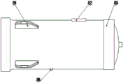
FIG. 1 is a block diagram of an adjustable thin-walled housing damping clamping device of the present invention.
Fig. 2 is a perspective view of the adjustable thin-walled housing damping clamping device of the present invention.
Fig. 3 is a block diagram of the retaining ring of the present invention.
Fig. 4 is a block diagram of a thin-walled housing for tooling of the present invention.
Detailed Description
The invention is further described below with reference to the accompanying drawings.
As shown in fig. 1-2, the adjustable thin-walled shell damping clamping device of the present invention comprises a mandrel 3 and a plurality of supporting wheels 4, wherein the mandrel 3 is a stepped shaft, the mandrel is divided into a chuck tensioning portion, a supporting wheel mounting portion and a threaded portion, the chuck tensioning portion and the threaded portion are respectively located at two ends of the mandrel, the diameter of the chuck tensioning portion is larger than the diameter of the supporting wheel mounting portion and the threaded portion, the chuck tensioning portion of the mandrel 3 is a cone frustum structure matched with a central hole of a three-jaw chuck 1, and the chuck tensioning portion can be inserted into the central hole of the three-jaw chuck 1 for fixation. A plurality of supporting wheels 4 set up at the supporting wheel installation department, and supporting wheel 4's centre bore and supporting wheel installation department clearance fit, supporting wheel 4 is coaxial with dabber 3. A positioning ring 5 is arranged between the adjacent supporting wheels 4; the threaded part is provided with a nut 7; a positioning ring 5 is arranged between the nut 7 and the adjacent supporting wheel 4.
Supporting wheel 4 and dabber 3 adopt the assembled structure, adopt holding ring 5 location, can increase and decrease the quantity of supporting wheel 4, can also be according to the position control supporting wheel 4 of the appearance characteristic of treating processing, make the appearance characteristic of treating processing obtain effectual support. And the assembled structure can replace the supporting wheel 4 for processing thin-wall shells with different sizes. The cylindrical side surface of the supporting wheel 4 is provided with an annular groove, a rubber ring 6 is arranged in the groove, and the rubber ring 6 is a silicon rubber ring. In order to better position the thin-wall shell, arc-shaped plates 2 are welded on the jaws of the three-jaw chuck 1, and the arc-shaped plates 2 are coaxial with the three-jaw chuck 1.
The invention discloses an operation method of an adjustable thin-wall shell vibration damping clamping device, which comprises the following steps:
1) inserting one end of a mandrel 3 into a central hole of a three-jaw chuck 1 of a machine tool, tensioning the mandrel through threads, and fixing a chuck tensioning part of the mandrel 3 on the three-jaw chuck 1;
2) sleeving the thin-wall shell 8 on the mandrel 2, wherein the open end of the thin-wall shell 8 faces the three-jaw chuck 1 of the machine tool; and the other end of the mandrel 3 is pressed against the bottom of the thin-wall shell 8; the clamping jaws of the three-jaw chuck 1 are adjusted, so that the arc-shaped plate 2 gradually tightens the positioning reference surface of the inner hole of the thin-wall shell;
3) a tail jack 9 is adopted to jack a center hole of a process table at the bottom of the thin-wall shell 8;
4) and starting the machine tool, aligning the surface 81 to be processed, the surface 82 to be processed, the surface 83 to be processed or the surface 84 to be processed of the thin-wall shell 8, and then starting to process the appearance characteristics of the thin-wall shell.
Claims (6)
1. The utility model provides a thin wall casing damping clamping device with adjustable which characterized by: the three-jaw chuck comprises a mandrel and a plurality of supporting wheels, wherein one end of the mandrel is of a cone frustum structure matched with a central hole of the three-jaw chuck; the supporting wheels are arranged on the mandrel in parallel and are coaxial with the mandrel; the supporting wheel is characterized in that an annular groove is formed in the cylindrical side face of the supporting wheel, and a rubber ring is arranged in the groove.
2. The adjustable thin-walled housing damping clamping device of claim 1, wherein: the mandrel is a stepped shaft and is divided into a chuck tensioning part, a supporting wheel mounting part and a threaded part, the chuck tensioning part and the threaded part are respectively positioned at two ends of the mandrel, the diameter of the chuck tensioning part is larger than that of the supporting wheel mounting part and the threaded part, and a plurality of supporting wheels are arranged on the supporting wheel mounting part and are in clearance fit with the supporting wheel mounting part; a positioning ring is arranged between the adjacent supporting wheels; the threaded part is provided with a nut; and a positioning ring is arranged between the nut and the adjacent supporting wheel.
3. The adjustable thin-walled housing damping clamping device of claim 1, wherein: the rubber ring is a silicon rubber ring.
4. The adjustable thin-walled housing damping clamping device of claim 1, wherein: the clamping jaws of the three-jaw chuck are welded with arc-shaped plates which are coaxial with the three-jaw chuck.
5. An operation method of the adjustable thin-wall shell damping clamping device as claimed in any one of claims 1 to 4, comprising the following steps:
1) inserting one end of a mandrel into a central hole of a three-jaw chuck of a machine tool, and tensioning the mandrel through threads;
2) sleeving the thin-wall shell on the mandrel, wherein the open end of the thin-wall shell faces to a three-jaw chuck of a machine tool; and the other end of the mandrel is propped against the bottom of the thin-wall shell;
3) the tail is adopted to prop against the central hole of the part process table;
4) and starting the machine tool, and after aligning the surface to be processed of the thin-wall shell, starting to process the appearance characteristics of the thin-wall shell.
6. The operating method of the adjustable thin-walled housing vibration damping clamping device according to claim 5, wherein in the step 2), the jaws of the three-jaw chuck are adjusted, so that the arc-shaped plate gradually tightens the positioning reference surface of the inner hole of the thin-walled housing.
Priority Applications (1)
| Application Number | Priority Date | Filing Date | Title |
|---|---|---|---|
| CN202010874296.5A CN112059674A (en) | 2020-08-27 | 2020-08-27 | Adjustable thin-wall shell vibration damping clamping device and operation method |
Applications Claiming Priority (1)
| Application Number | Priority Date | Filing Date | Title |
|---|---|---|---|
| CN202010874296.5A CN112059674A (en) | 2020-08-27 | 2020-08-27 | Adjustable thin-wall shell vibration damping clamping device and operation method |
Publications (1)
| Publication Number | Publication Date |
|---|---|
| CN112059674A true CN112059674A (en) | 2020-12-11 |
Family
ID=73658964
Family Applications (1)
| Application Number | Title | Priority Date | Filing Date |
|---|---|---|---|
| CN202010874296.5A Pending CN112059674A (en) | 2020-08-27 | 2020-08-27 | Adjustable thin-wall shell vibration damping clamping device and operation method |
Country Status (1)
| Country | Link |
|---|---|
| CN (1) | CN112059674A (en) |
Cited By (1)
| Publication number | Priority date | Publication date | Assignee | Title |
|---|---|---|---|---|
| CN114310367A (en) * | 2021-12-23 | 2022-04-12 | 上海新力动力设备研究所 | Large length-diameter ratio thin-wall shell vibration reduction tool |
-
2020
- 2020-08-27 CN CN202010874296.5A patent/CN112059674A/en active Pending
Cited By (1)
| Publication number | Priority date | Publication date | Assignee | Title |
|---|---|---|---|---|
| CN114310367A (en) * | 2021-12-23 | 2022-04-12 | 上海新力动力设备研究所 | Large length-diameter ratio thin-wall shell vibration reduction tool |
Similar Documents
| Publication | Publication Date | Title |
|---|---|---|
| CN109396766B (en) | Thin-wall shell machining process method | |
| CN201988972U (en) | Turning fixture of thin-wall sleeve | |
| CN207103885U (en) | A kind of internal expansion type fixture | |
| CN106541290A (en) | A kind of jig of the circumferential registration for thin-wall part processing | |
| CN113458433A (en) | Clamping tool for processing external thread of large thin-wall cylinder | |
| CN203804344U (en) | Non-backlash centering auto-compensation positioning device | |
| CN212240194U (en) | Thin wall casing damping clamping device with adjustable | |
| CN112059674A (en) | Adjustable thin-wall shell vibration damping clamping device and operation method | |
| CN109128885A (en) | Thin-wall tube-shaped excircle of workpiece turning clamping tooling and clamping method | |
| CN209255878U (en) | A kind of lathe auxiliary jig for pipe fitting processing | |
| CN108942343B (en) | Novel clamp for outer circle of crankshaft eccentric shaft of air conditioner compressor | |
| CN216226989U (en) | Spline internal expanding machine tool clamp with good reliability | |
| CN206169717U (en) | But rapid Assembly's combination formula dabber | |
| CN204954619U (en) | Bearing inner race cylindrical grinding fixture device | |
| CN110682120B (en) | Positioning and supporting device for machining thin-wall shell parts | |
| CN213052885U (en) | Self-centering rapid drilling clamp for rocker shaft of speed regulator | |
| CN110039261B (en) | Machining method of bow-shaped part | |
| CN2429294Y (en) | Clamping tool for machining thin plates | |
| CN114289749A (en) | Clamp for machining eccentric excircle and clamping method | |
| CN1006862B (en) | Combined core-axle | |
| CN113118801A (en) | Special fixture for copper bush part machining | |
| CN106180783A (en) | Elongated thin metallic tubd processing mold and mould, metal tube processing method | |
| CN104759922A (en) | Turning method for inclined bend shaft | |
| CN220161326U (en) | Lathe fixture for machining motor shell | |
| CN219541922U (en) | Gear shaping fixture for machining inner teeth of thin-wall clutch hub |
Legal Events
| Date | Code | Title | Description |
|---|---|---|---|
| PB01 | Publication | ||
| PB01 | Publication | ||
| SE01 | Entry into force of request for substantive examination | ||
| SE01 | Entry into force of request for substantive examination |