CN112051443B - Device for measuring electric power - Google Patents
Device for measuring electric power Download PDFInfo
- Publication number
- CN112051443B CN112051443B CN202011184057.3A CN202011184057A CN112051443B CN 112051443 B CN112051443 B CN 112051443B CN 202011184057 A CN202011184057 A CN 202011184057A CN 112051443 B CN112051443 B CN 112051443B
- Authority
- CN
- China
- Prior art keywords
- measuring
- amplifier
- resistor
- reactive power
- power
- Prior art date
- Legal status (The legal status is an assumption and is not a legal conclusion. Google has not performed a legal analysis and makes no representation as to the accuracy of the status listed.)
- Active
Links
Images


Classifications
-
- G—PHYSICS
- G01—MEASURING; TESTING
- G01R—MEASURING ELECTRIC VARIABLES; MEASURING MAGNETIC VARIABLES
- G01R21/00—Arrangements for measuring electric power or power factor
- G01R21/133—Arrangements for measuring electric power or power factor by using digital technique
Abstract
The invention discloses a device for measuring electric power, and relates to the technical field of electronic detection; the device comprises an amplifier for measuring the active power, first to fourth resistors and a multiplier, wherein a non-inverting input end of the amplifier for measuring the active power is connected to a third resistor for measuring the active power, the non-inverting input end of the amplifier for measuring the active power is connected to the ground through the fourth resistor for measuring the active power, an inverting input end of the amplifier for measuring the active power is connected to the ground through a first resistor for measuring the active power, a second resistor for measuring the active power is connected between the inverting input end and the output end of the amplifier for measuring the active power, and the output end of the amplifier for measuring the active power is connected with a second input end of the multiplier for measuring the active power; the device for measuring the electric power in the operation of the power transmission line of the power grid is provided by an amplifier for measuring the active power, first to fourth resistors, a multiplier and the like.
Description
Technical Field
The invention relates to the technical field of electronic detection, in particular to a device for measuring electric power.
Background
The system or equipment simulation technology of the power grid mainly comprises three types of RTDS, an AC/DC electromagnetic transient simulation platform, a power grid system movable mould and the like. The descriptions are as follows:
RTDS is known as real-time digital simulator (Real Time Digital Simulator), developed and manufactured by Tony RTDS, canada, is a device specially designed for researching electromagnetic transient phenomena in a power system. RTDS has been widely used in power enterprises and research institutions in 28 countries (regions), with an installed number exceeding 140. The grid model, generator, load and controller models of the RTDS are all digital and are modeled by software. The system has the current and voltage quantity simulated by software, and is converted into the actual current and voltage quantity through digital-to-analog conversion. These output currents, voltage amounts can be used to drive protections, automation, etc., for testing the reliability of the protections, automation, and the rationality of the algorithm.
The RTDS model is simulated by digital software, and the real current and voltage quantity is output only at the output end by adopting a digital-to-analog conversion technology, and the RTDS works at 50Hz.
The AC/DC electromagnetic transient simulation platform is a digital-analog hybrid simulation system and a digital hybrid simulation system which are independently developed by the Chinese electric department, the simulation capability and technology are at the most advanced international level, and the system is applied to the Chinese electric department and each power-saving department. The platform integrates the functions of power flow calculation, steady-state analysis, electromagnetic transient analysis, analog-to-digital conversion, hardware output current and voltage. The simulation range can cover the ultra-large power grid in the whole China, and the simulation time scale ranges from the steady state phenomenon of the small time scale to the electromagnetic transient phenomenon of the microsecond level. The method is mainly characterized by not only outputting real current and voltage by digital-to-analog conversion like RTDS, but also effectively fusing and linking various digital-to-analog means, and greatly expanding the simulation scale on time scale and space scale.
The AC/DC electromagnetic transient simulation platform is basically the same as RTDS, the model of the AC/DC electromagnetic transient simulation platform is also simulated by digital software, the real current and voltage quantity is output only by adopting a digital-to-analog conversion technology at the output end, the working frequency of an analog object of the AC/DC electromagnetic transient simulation platform is 50Hz, and the AC/DC electromagnetic transient simulation platform is required to obtain the simulation of the millisecond time scale which is subdivided from the small time scale in the whole Chinese power grid range, and the investment scale is huge.
The power grid system movable mould is a classical system of power grid simulation. In the 60 and 70 s, which are not very popular, digital computers are important devices for researching power systems. Equipment is available at the time in the electric power system profession of the Chinese electric academy and the universities and colleges. The simulation scale is generally two to four generators and corresponding loads, and the simulation scale serves the research of electromagnetic and mechanical dynamics of an electric power system. The physical simulation model of the electric power system is built according to the similarity principle, each part of the actual electric power system is designed and built according to similar conditions to form a small-scale electric power system, and the model is used for replacing the actual electric power system to carry out experimental study of various normal and fault states. The current movable mould system introduces modern information and electronic technology, can realize distributed digital network measurement, can be closely combined with RTDS and other systems and is mutually complemented.
The power grid system movable mould regards the power transmission line as an integral part, and the power grid system movable mould works at 50Hz, and the influence of parameters such as the internal size, layout and the like of the power transmission line on the electrical property of the power transmission line cannot be studied.
The electric power includes active electric power, i.e., active and reactive electric power, i.e., reactive.
Problems and considerations in the prior art:
how to solve the technical problem of providing a device for measuring electric power in the operation of analyzing the transmission line of a power grid.
Disclosure of Invention
The technical problem to be solved by the invention is to provide a device for measuring electric power, which is realized by an amplifier for measuring active power, first to fourth resistors, a multiplier and the like, and the device for measuring the electric power in the work of a power transmission line of an analysis power grid is provided.
In order to solve the technical problems, the invention adopts the following technical scheme: an apparatus for measuring electric power comprises an amplifier for measuring active power, first to fourth resistors and a multiplier, wherein a positive input end of the amplifier for measuring active power is connected to a third resistor for measuring active power, a positive input end of the amplifier for measuring active power is connected to ground through the fourth resistor for measuring active power, an inverting input end of the amplifier for measuring active power is connected to ground through the first resistor for measuring active power, a second resistor for measuring active power is connected between the inverting input end and the output end of the amplifier for measuring active power, an output end of the amplifier for measuring active power is connected with a second input end of the multiplier for measuring active power, and the amplifier for measuring active power, the first to fourth resistors and the multiplier form an active power measuring unit.
The further technical proposal is that: the non-inverting input end of the amplifier for measuring the active power is connected to the voltage end to be measured through a third resistor for measuring the active power, and the first input end of the multiplier for measuring the active power is connected to the current end to be measured; the amplifier for measuring the active power is an operational amplifier, the multiplier for measuring the active power is an analog multiplier, the first resistor for measuring the active power is a resistor with the resistance range of 0.5 kiloohm-10 kiloohms, the second resistor for measuring the active power is a resistor with the resistance range of 0.5 kiloohm-10 kiloohms, the third resistor for measuring the active power is a resistor with the resistance range of 1 kiloohm-50 kiloohms, and the fourth resistor for measuring the active power is a resistor with the resistance range of 0.1 kiloohm-5 kiloohms.
The further technical proposal is that: the first resistor for measuring the power is a resistor with a resistance value of 1 kiloohm, the second resistor for measuring the power is a resistor with a resistance value of 1 kiloohm, the third resistor for measuring the power is a resistor with a resistance value of 9 kiloohms, and the fourth resistor for measuring the power is a resistor with a resistance value of 1 kiloohm.
The further technical proposal is that: the reactive power measuring device further comprises an amplifier for measuring reactive power, first to third resistors, a capacitor and a multiplier, wherein the normal phase input end of the amplifier for measuring reactive power is connected to the third resistor for measuring reactive power, the normal phase input end of the amplifier for measuring reactive power is connected to the ground through the capacitor for measuring reactive power, the reverse phase input end of the amplifier for measuring reactive power is connected to the ground through the first resistor for measuring reactive power, the second resistor for measuring reactive power is connected between the reverse phase input end and the output end of the amplifier for measuring reactive power, the output end of the amplifier for measuring reactive power is connected with the second input end of the multiplier for measuring reactive power, and the amplifier for measuring reactive power, the first to third resistors, the capacitor and the multiplier form a reactive power measuring unit.
An apparatus for measuring electric power comprises an amplifier for measuring reactive power, a first to a third resistor, a capacitor and a multiplier, wherein the positive input end of the amplifier for measuring reactive power is connected to the third resistor for measuring reactive power, the positive input end of the amplifier for measuring reactive power is connected to the ground through the capacitor for measuring reactive power, the negative input end of the amplifier for measuring reactive power is connected to the ground through the first resistor for measuring reactive power, the second resistor for measuring reactive power is connected between the negative input end and the output end of the amplifier for measuring reactive power, the output end of the amplifier for measuring reactive power is connected with the second input end of the multiplier for measuring reactive power, and the amplifier for measuring reactive power, the first to the third resistor, the capacitor and the multiplier form a reactive power measuring unit.
The device for measuring the electric power comprises a current-voltage measuring unit and an active and reactive measuring unit, wherein the active and reactive measuring unit comprises an active measuring unit and a reactive measuring unit, and the output end of the current-voltage measuring unit is respectively connected with the input end of the active measuring unit and the input end of the reactive measuring unit; the reactive power measuring unit comprises an amplifier for measuring reactive power, first to third resistors, a capacitor and a multiplier, wherein the normal phase input end of the amplifier for measuring reactive power is connected to the third resistor for measuring reactive power, the normal phase input end of the amplifier for measuring reactive power is connected to the ground through the capacitor for measuring reactive power, the reverse phase input end of the amplifier for measuring reactive power is connected to the ground through the first resistor for measuring reactive power, the second resistor for measuring reactive power is connected between the reverse phase input end and the output end of the amplifier for measuring reactive power, and the output end of the amplifier for measuring reactive power is connected with the second input end of the multiplier for measuring reactive power.
The further technical proposal is that: the current-voltage measuring unit comprises a first voltage amplifier, a second voltage amplifier and a current sampling resistor, wherein the first voltage amplifier is used for measuring current and voltage, the positive input end of the first voltage amplifier is connected with the output end of a signal source, the negative input end of the first voltage amplifier is connected with the positive input end of the second voltage amplifier, the negative input end of the second voltage amplifier is grounded, the current sampling resistor is connected between the positive input end and the negative input end of the first voltage amplifier, the output end of the first voltage amplifier is connected with the current input end of the active measuring unit and the current input end of the reactive measuring unit, and the output end of the second voltage amplifier is connected with the voltage input end of the active measuring unit and the voltage input end of the reactive measuring unit.
The further technical proposal is that: the non-inverting input end of the amplifier for measuring reactive power is connected to a voltage end to be measured through a third resistor for measuring reactive power, and the first input end of the multiplier for measuring reactive power is connected to a current end to be measured; the amplifier for measuring reactive power is an operational amplifier, the multiplier for measuring reactive power is an analog multiplier, the first resistor for measuring reactive power is a resistor with a resistance range of 0.5 kiloohm to 10 kiloohms, the second resistor for measuring reactive power is a resistor with a resistance range of 0.5 kiloohm to 10 kiloohms, the third resistor for measuring reactive power is a resistor with a resistance range of 1 kiloohm to 50 kiloohms, and the capacitor for measuring reactive power is a capacitor with a capacitance range of 20 picofarads to 200 picofarads.
The further technical proposal is that: the first resistor for measuring the reactive power is a resistor with a resistance value of 1 kiloohm, the second resistor for measuring the reactive power is a resistor with a resistance value of 1 kiloohm, the third resistor for measuring the reactive power is a resistor with a resistance value of 3 kiloohms, and the capacitor for measuring the reactive power is a capacitor with a capacitance value of 100 picofarads.
The further technical proposal is that: the first voltage amplifier and the second voltage amplifier for measuring the current and the voltage are differential operational amplifiers, and the current sampling resistor for measuring the current and the voltage is a resistor with the resistance ranging from 1 ohm to 20 ohms.
The beneficial effects of adopting above-mentioned technical scheme to produce lie in:
the device for measuring the electric power in the operation of the power transmission line of the power grid is provided by an amplifier for measuring the active power, first to fourth resistors, a multiplier and the like.
See the description of the detailed description section.
Drawings
FIG. 1 is a schematic block diagram of embodiment 1 of the present invention;
fig. 2 is a schematic block diagram of the invention applied to a grid transmission line analysis system;
FIG. 3 is a schematic block diagram of a signal source, a meter, and a bench model in the present invention;
FIG. 4 is a schematic circuit diagram of a signal source in the present invention;
FIG. 5 is a schematic circuit diagram of a first circuit A-phase current-voltage measurement unit according to the present invention;
FIG. 6 is a schematic circuit diagram of a first line B-phase current-voltage measurement unit according to the present invention;
FIG. 7 is a schematic circuit diagram of a first line C-phase current-voltage measurement unit according to the present invention;
FIG. 8 is a schematic circuit diagram of a second line phase A current-voltage measurement unit according to the present invention;
FIG. 9 is a schematic circuit diagram of a second line B-phase current-voltage measurement unit according to the present invention;
FIG. 10 is a schematic circuit diagram of a second line C-phase current-voltage measurement unit according to the present invention;
fig. 11 is a schematic circuit diagram of a bench model in accordance with the invention.
Detailed Description
The following description of the embodiments of the present application will be made clearly and fully with reference to the accompanying drawings, in which it is evident that the embodiments described are only some, but not all, of the embodiments of the present application. The following description of at least one exemplary embodiment is merely exemplary in nature and is in no way intended to limit the application, its application, or uses. All other embodiments, which can be made by one of ordinary skill in the art without undue burden from the present disclosure, are within the scope of the present disclosure.
In the following description, numerous specific details are set forth in order to provide a thorough understanding of the present application, but the present application may be practiced in other ways other than those described herein, and persons skilled in the art will readily appreciate that the present application is not limited to the specific embodiments disclosed below.
Example 1:
as shown in fig. 1, the present invention discloses an apparatus for measuring electric power including an active measuring unit including an amplifier for measuring active, first to fourth resistors, and a multiplier, and a reactive measuring unit including an amplifier for measuring reactive, first to third resistors, a capacitor, and a multiplier. The positive input end of the amplifier for measuring the active power is connected to a third resistor for measuring the active power, the positive input end of the amplifier for measuring the active power is connected to the ground through a fourth resistor for measuring the active power, the negative input end of the amplifier for measuring the active power is connected to the ground through a first resistor for measuring the active power, the second resistor for measuring the active power is connected between the negative input end and the output end of the amplifier for measuring the active power, the output end of the amplifier for measuring the active power is connected with the second input end of a multiplier for measuring the active power, and the amplifier for measuring the active power, the first resistor to the fourth resistor and the multiplier form an active power measuring unit.
The non-inverting input end of the amplifier for measuring reactive power is connected to a third resistor for measuring reactive power, the non-inverting input end of the amplifier for measuring reactive power is connected to the ground through a capacitor for measuring reactive power, the inverting input end of the amplifier for measuring reactive power is connected to the ground through a first resistor for measuring reactive power, the second resistor for measuring reactive power is connected between the inverting input end and the output end of the amplifier for measuring reactive power, the output end of the amplifier for measuring reactive power is connected with the second input end of a multiplier for measuring reactive power, and the amplifier for measuring reactive power, the first resistor, the third resistor, the capacitor and the multiplier form a reactive power measuring unit.
The non-inverting input end of the amplifier for measuring the active power is connected to the voltage end to be measured through a third resistor for measuring the active power, and the first input end of the multiplier for measuring the active power is connected to the current end to be measured. The non-inverting input end of the amplifier for measuring reactive power is connected to the voltage end to be measured through a third resistor for measuring reactive power, and the first input end of the multiplier for measuring reactive power is connected to the current end to be measured.
Example 2:
The invention discloses a device for measuring electric power, which comprises an amplifier for measuring the active power, first to fourth resistors and a multiplier, wherein the positive input end of the amplifier for measuring the active power is connected to a third resistor for measuring the active power, the positive input end of the amplifier for measuring the active power is connected to the ground through the fourth resistor for measuring the active power, the negative input end of the amplifier for measuring the active power is connected to the ground through the first resistor for measuring the active power, the second resistor for measuring the active power is connected between the negative input end and the output end of the amplifier for measuring the active power, the output end of the amplifier for measuring the active power is connected with the second input end of the multiplier for measuring the active power, and the amplifier for measuring the active power, the first to fourth resistors and the multiplier form an active power measuring unit. The non-inverting input end of the amplifier for measuring the active power is connected to the voltage end to be measured through a third resistor for measuring the active power, and the first input end of the multiplier for measuring the active power is connected to the current end to be measured.
Example 3:
the invention discloses a device for measuring electric power, which comprises an amplifier for measuring reactive power, first to third resistors, a capacitor and a multiplier, wherein a positive input end of the amplifier for measuring reactive power is connected to the third resistor for measuring reactive power, a positive input end of the amplifier for measuring reactive power is connected to ground through the capacitor for measuring reactive power, an inverting input end of the amplifier for measuring reactive power is connected to the ground through the first resistor for measuring reactive power, a second resistor for measuring reactive power is connected between the inverting input end and the output end of the amplifier for measuring reactive power, an output end of the amplifier for measuring reactive power is connected with a second input end of the multiplier for measuring reactive power, and the amplifier for measuring reactive power, the first to third resistors, the capacitor and the multiplier form a reactive power measuring unit. The non-inverting input end of the amplifier for measuring reactive power is connected to the voltage end to be measured through a third resistor for measuring reactive power, and the first input end of the multiplier for measuring reactive power is connected to the current end to be measured.
Application description:
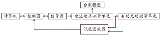
as shown in fig. 2, a power grid transmission line analysis system is built, the power grid transmission line analysis system comprises a computer, a controller, a signal source, a bench model based on the reduced power grid transmission line, a measuring instrument for measuring voltage and current and a low-pass filter, wherein the computer is electrically connected with the controller and is in bidirectional communication, the controller is electrically connected with the signal source and is in bidirectional communication, an output port of the signal source is electrically connected with an input port of the measuring instrument, a first output port of the measuring instrument is electrically connected with an input port of the bench model, a second output port of the measuring instrument is electrically connected with a first input port of the low-pass filter, a third output port of the measuring instrument is electrically connected with a second input port of the low-pass filter, and an output end of the low-pass filter is connected with an input end of the controller and is in unidirectional communication, so that the voltage, current, active power and reactive power of the bench model are obtained, and the power grid transmission line analysis system is described below.
Signal source:
as shown in fig. 4, the signal source includes a signal generator U1-1, first to fourth voltage amplifiers U2-1 to U5-1 for forming the signal source, first to fourth current amplifiers U6-1 to U9-1 and first to fourth output terminals a_out-1 to c_out-1, o_out-1, and the first to fourth voltage amplifiers U2-1 to U5-1 for forming the signal source and the first to fourth current amplifiers U6-1 to U9-1 form four amplifying circuits for forming the signal source having the same structure.
The first output end D0_OUT of the signal generator U1-1 is connected with a non-inverting input end of a first voltage amplifier U2-1 used for forming a signal source, an inverting input end of the first voltage amplifier U2-1 used for forming the signal source is grounded GND, an output end of the first voltage amplifier U2-1 used for forming the signal source is connected with an input end of a first current amplifier U6-1 used for forming the signal source, an output end of the first current amplifier U6-1 used for forming the signal source is connected with a first output terminal A_OUT-1 used for forming the signal source, an A phase is output at the first output terminal A_OUT-1 used for forming the signal source, and the first voltage amplifier U2-1 and the first current amplifier U6-1 used for forming the signal source form a first amplifying circuit used for forming the signal source.
The second output end D1-OUT of the signal generator U1-1 is connected with a non-inverting input end of a second voltage amplifier U3-1 used for forming a signal source, an inverting input end of the second voltage amplifier U3-1 used for forming the signal source is grounded GND, an output end of the second voltage amplifier U3-1 used for forming the signal source is connected with an input end of a second current amplifier U7-1 used for forming the signal source, an output end of the second current amplifier U7-1 used for forming the signal source is connected with a second output terminal B_OUT-1 used for forming the signal source, a B phase is output at the second output terminal B_OUT-1 used for forming the signal source, and the second voltage amplifier U3-1 and the second current amplifier U7-1 used for forming the signal source form a second amplifying circuit used for forming the signal source.
The third output end D2-OUT of the signal generator U1-1 is connected with a non-inverting input end of the third voltage amplifier U4-1 used for forming a signal source, an inverting input end of the third voltage amplifier U4-1 used for forming the signal source is grounded GND, an output end of the third voltage amplifier U4-1 used for forming the signal source is connected with an input end of the third current amplifier U8-1 used for forming the signal source, an output end of the third current amplifier U8-1 used for forming the signal source is connected with a third output terminal C-OUT-1 used for forming the signal source, a C phase is output at the third output terminal C-OUT-1 used for forming the signal source, and the third voltage amplifier U4-1 and the third current amplifier U8-1 used for forming the signal source form a third amplifying circuit used for forming the signal source.
The fourth output end D3-OUT of the signal generator U1-1 is connected with a non-inverting input end of a fourth voltage amplifier U5-1 used for forming a signal source, an inverting input end of the fourth voltage amplifier U5-1 used for forming the signal source is grounded GND, an output end of the fourth voltage amplifier U5-1 used for forming the signal source is connected with an input end of a fourth current amplifier U9-1 used for forming the signal source, an output end of the fourth current amplifier U9-1 used for forming the signal source is connected with a fourth output terminal O_OUT-1 used for forming the signal source, a reference signal is output at the fourth output terminal O_OUT-1 used for forming the signal source, and the fourth voltage amplifier U5-1 and the fourth current amplifier U9-1 used for forming the signal source form a fourth amplifying circuit used for forming the signal source.
As shown in fig. 3 and 4, the first output terminal a_out-1, the second output terminal b_out-1, the third output terminal c_out-1, and the fourth output terminal o_out-1 for forming the signal source form the output port of the signal source.
The signal generator U1-1 is a high-speed DDS chip, the model is AD9959, the first to fourth voltage amplifiers U2-1 to U5-1 for forming the signal source are high-speed differential operational amplifiers, the model is AD8130, the first to fourth current amplifiers U6-1 to U9-1 are high-speed buffers, the model is BUF634T, and the signal generator, the voltage amplifiers and the current amplifiers themselves and the corresponding communication connection technology are not described in detail herein.
Measuring instrument:
as shown in fig. 2, the measuring instrument includes a first measuring unit for measuring current and voltage, which is a current and voltage measuring unit, and a second measuring unit for measuring active and reactive, which is an active and reactive measuring unit.
As shown in fig. 5 to 10, the current-voltage measurement units include six current-voltage measurement units with the same structure, which are respectively a first line a-phase current-voltage measurement unit, a first line B-phase current-voltage measurement unit, a first line C-phase current-voltage measurement unit, a second line a-phase current-voltage measurement unit, a second line B-phase current-voltage measurement unit and a second line C-phase current-voltage measurement unit, wherein the six current-voltage measurement units with the same structure form two groups of three-phase current-voltage measurement units, the two groups of three-phase current-voltage measurement units are respectively a first line three-phase current-voltage measurement unit and a second line three-phase current-voltage measurement unit with the same structure, the first line a-C-phase current-voltage measurement units form a first line three-phase current-voltage measurement unit, and the second line a-C-phase current-voltage measurement units form a second line three-phase current-voltage measurement unit.
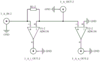
As shown in fig. 5, the first line a phase current voltage measurement unit includes a first voltage amplifier U1-2 for measuring a first line a phase current voltage, a second voltage amplifier U2-2, a signal source terminal 1_a_in-2, a current collection output terminal 1_a_i_out-2, a voltage collection output terminal 1_u_out-2, an excitation terminal 1_a_out-2, and a current sampling resistor R1-2, the signal source terminal 1_a_in-2 for measuring a first line a phase current voltage is connected to a positive phase input terminal of the first voltage amplifier U1-2 for measuring a first line a phase current voltage, an inverting input terminal of the first voltage amplifier U1-2 for measuring a first line a phase current voltage is connected to a positive phase input terminal of the second voltage amplifier U2-2 for measuring a first line a phase current voltage, an inverting input terminal of the first voltage amplifier U2-2 for measuring a phase current voltage is connected to a positive phase input terminal GND for measuring a first line a phase current voltage, an inverting input terminal of the first voltage amplifier U2-2 for measuring a phase current voltage is connected to the first voltage amplifier U2 for measuring a first line a phase current voltage is connected to the first phase current input terminal for measuring a current voltage of the first line a phase current voltage of the first line a 1-2, an inverting input terminal for measuring a current voltage of the first line a phase current is connected to the first voltage amplifier U2-2 for measuring a phase current output terminal for measuring a current voltage of the first phase current a current 1-2 is connected to the first phase current output terminal 1-2, the voltage acquisition output terminal 1_a_u_out-2 for measuring the first line a phase current voltage is connected to the output of the second voltage amplifier U2-2 for measuring the first line a phase current voltage. The current sampling resistor R1-2 for measuring the A-phase current voltage of the first line is a resistor with a resistance value of 5 ohms.
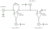
As shown in fig. 6, the first line B-phase current-voltage measurement unit includes a first voltage amplifier U3-2 for measuring the first line B-phase current voltage, a second voltage amplifier U4-2, a signal source terminal 1_b_in-2, a current collection output terminal 1_b_i_out-2, a voltage collection output terminal 1_b_u_out-2, an excitation terminal 1_b_out-2, and a current sampling resistor R2-2.
As shown in fig. 7, the first line C-phase current-voltage measurement unit includes a first voltage amplifier U5-2 for measuring the first line C-phase current voltage, a second voltage amplifier U6-2, a signal source terminal 1_c_in-2, a current collection output terminal 1_c_i_out-2, a voltage collection output terminal 1_c_u_out-2, an excitation terminal 1_c_out-2, and a current sampling resistor R3-2.
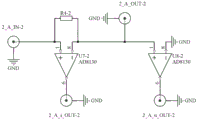
As shown in fig. 8, the second line a phase current-voltage measurement unit includes a first voltage amplifier U7-2 for measuring a second line a phase current voltage, a second voltage amplifier U8-2, a signal source terminal 2_a_in-2, a current collection output terminal 2_a_i_out-2, a voltage collection output terminal 2_a_u_out-2, an excitation terminal 2_a_out-2, and a current sampling resistor R4-2.
As shown in fig. 9, the second line B-phase current-voltage measurement unit includes a first voltage amplifier U9-2 for measuring a second line B-phase current voltage, a second voltage amplifier U10-2, a signal source terminal 2_b_in-2, a current collection output terminal 2_b_i_out-2, a voltage collection output terminal 2_b_u_out-2, an excitation terminal 2_b_out-2, and a current sampling resistor R5-2.
As shown in fig. 10, the second line C-phase current-voltage measurement unit includes a first voltage amplifier U11-2 for measuring a second line C-phase current voltage, a second voltage amplifier U12-2, a signal source terminal 2_c_in-2, a current collection output terminal 2_c_i_out-2, a voltage collection output terminal 2_c_u_out-2, an excitation terminal 2_c_out-2, and a current sampling resistor R6-2.
The first voltage amplifier and the second voltage amplifier of each current-voltage measurement unit are high-speed differential operational amplifiers, the model is AD8130, the current sampling resistor of each current-voltage measurement unit is a resistor with a resistance value of 5 ohms, and the voltage amplifiers and the corresponding communication connection technology are not described in detail in the prior art.
The active and reactive power measuring units comprise six active and reactive power measuring units with the same structure, namely a first circuit A-phase active and reactive power measuring unit, a first circuit B-phase active and reactive power measuring unit, a first circuit C-phase active and reactive power measuring unit, a second circuit A-phase active and reactive power measuring unit, a second circuit B-phase active and reactive power measuring unit and a second circuit C-phase active and reactive power measuring unit, wherein the six active and reactive power measuring units with the same structure form two groups of three-phase active and reactive power measuring units, the two groups of three-phase active and reactive power measuring units are respectively a first circuit three-phase active and reactive power measuring unit and a second circuit three-phase active and reactive power measuring unit with the same structure, the first circuit A-C-phase active and reactive power measuring units form a first circuit three-phase active and reactive power measuring unit, and the second circuit A-C-phase active and reactive power measuring units form a second circuit three-phase active and reactive power measuring unit.
As shown in fig. 1, the first line a phase active/reactive measurement unit includes an amplifier U1-3 for measuring the first line a phase active/reactive, first to fourth resistors r1_1-3 to r1_4-3, a multiplier U3-3 and an active output terminal 1_a_p_out-3, an amplifier U2-3 for measuring the first line a phase reactive, first to third resistors r2_1-3 to r2_3, a capacitor c2_1-3, a multiplier U4-3 and a reactive output terminal 1_a_q_out-3, and a voltage input terminal 1_a_in-3 and a current input terminal 1_i_in-3 for measuring the first line a phase active/reactive, the positive phase input terminal of the amplifier U1-3 for measuring the first line a phase active/reactive is connected to the voltage input terminal 1_a_3 for measuring the first line a phase active/reactive via a third resistor r1_3-3 for measuring the first line a phase active/reactive, the positive input end of the amplifier U1-3 for measuring the active power of the first line A is connected to the ground GND through a fourth resistor R1_4-3 for measuring the active power of the first line A, the negative input end of the amplifier U1-3 for measuring the active power of the first line A is connected to the ground GND through a first resistor R1_1-3 for measuring the active power of the first line A, a second resistor R1_2-3 for measuring the active power of the first line A is connected between the negative input end and the output end of the amplifier U1-3 for measuring the active power of the first line A, a current input terminal 1_A_i_IN-3 for measuring the active power and the reactive power of the first line A is connected with the first input end of a multiplier U3-3 for measuring the active power of the first line A, the output end of the amplifier U1-3 for measuring the phase A of the first line is connected with the second input end of the multiplier U3-3 for measuring the phase A of the first line, and the output end of the multiplier U3-3 for measuring the phase A of the first line is connected with the active output terminal 1_A_P_OUT-3 for measuring the phase A of the first line.
The positive input end of the amplifier U2-3 for measuring the reactive power of the first line A is connected to the ground GND through the third resistor R2_3-3 for measuring the reactive power of the first line A, the positive input end of the amplifier U2-3 for measuring the reactive power of the first line A is connected to the ground GND through the capacitor C2_1-3 for measuring the reactive power of the first line A, the inverting input end of the amplifier U2-3 for measuring the reactive power of the first line A is connected to the ground GND through the first resistor R2_1-3 for measuring the reactive power of the first line A, the second resistor R2_2-3 for measuring the reactive power of the first line A is connected between the inverting input end and the output end of the amplifier U2-3 for measuring the reactive power of the first line A, the current input terminal 1_I_IN-3 for measuring the active power and the reactive power of the first line A is connected to the first multiplier U3 for measuring the reactive power of the first line A, and the inverting input end of the amplifier U4_3 for measuring the reactive power of the first line A is connected to the first line A3 for measuring the reactive power of the first line A, and the inverting input end of the amplifier U3 for measuring the reactive power of the first line A is connected to the reactive power of the first line A3.
The first line B phase active and reactive power measuring unit comprises an amplifier for measuring the active power of the first line B phase, first to fourth resistors, a multiplier and an active output terminal 1_B_P_OUT-3, an amplifier for measuring the reactive power of the first line B phase, first to third resistors, a capacitor, a multiplier and a reactive output terminal 1_B_Q_OUT-3, a voltage input terminal 1_B_u_IN-3 for measuring the active power and reactive power of the first line B phase, a current input terminal 1_B_i_IN-3, a first line C phase active and reactive power measuring unit comprises an amplifier for measuring the active power of the first line C phase, first to fourth resistors, a multiplier and an active output terminal 1_C_P_OUT-3, an amplifier for measuring the reactive power of the first line C phase, a first to third resistor, a capacitor, a multiplier and a reactive output terminal 1_C_Q_OUT-3, and a voltage input terminal 1_C_IN-3 for measuring the active power of the first line B phase and reactive power, a voltage input terminal 1_U_IN-3 for measuring the active power of the first line C phase, a second line C phase and a reactive power input terminal 1_I_N-3, a multiplier and a reactive power amplifier for measuring the active power of the first line C phase, a second line C phase and a reactive power output terminal 1_P_OUT-3, a first to a multiplier and a reactive power output terminal 2_P_OUT-3, a first to a fourth resistor and a reactive power amplifier for measuring the active power of the first line C phase, a first to a reactive power output terminal 1_C_P_P_OUT-3, a voltage input terminal 1_C_C_P_OUT-3, a voltage and a voltage input terminal 1_Q_Q_Q_Q_OUT-3, a voltage and a voltage input for measuring the active power and a voltage The multiplier and reactive output terminal 2_b_q_out-3 and the voltage input terminal 2_b_u_in-3 and the current input terminal 2_b_i_in-3 for measuring the second line B phase active and reactive, the second line C phase active and reactive measuring unit comprises an amplifier for measuring the second line C phase active, first to fourth resistors, multiplier and active output terminal 2_c_p_out-3, an amplifier for measuring the second line C phase reactive, first to third resistors, capacitor, multiplier and reactive output terminal 2_c_q_out-3 and the voltage input terminal 2_c_u_in-3 and the current input terminal 2_c_i_in-3 for measuring the second line C phase active and reactive.
The amplifier of each active and reactive power measuring unit is a high-speed operational amplifier, the model is AD8017, the multiplier of each active and reactive power measuring unit is a high-speed analog multiplier, the model is AD835, the first resistor of each active and reactive power measuring unit for measuring the active power is a resistor with the resistance value of 1 kiloohm, the second resistor of each active and reactive power measuring unit for measuring the active power is a resistor with the resistance value of 1 kiloohm, the third resistor of each active and reactive power measuring unit for measuring the active power is a resistor with the resistance value of 9 kiloohms, the fourth resistor of each active and reactive power measuring unit for measuring the active power is a resistor with the resistance value of 1 kiloohm, the first resistor of each active and reactive power measuring unit for measuring the reactive power is a resistor with the resistance value of 1 kiloohm, the second resistor of each active and reactive power measuring unit for measuring the reactive power is a resistor with the resistance value of 3 kiloohm, the third resistor of each active and reactive power measuring unit for measuring the reactive power is a resistor with the resistance value of 3 kiloohm, and the reactive power measuring unit for measuring the reactive power is a capacitor of 100 which is connected with the communication technology in a communication mode.
As shown in fig. 3, the signal source terminal 1_a_in-2 for measuring the first line a phase current voltage, the signal source terminal 1_b_in-2 for measuring the first line B phase current voltage, the signal source terminal 1_c_in-2 for measuring the first line C phase current voltage, the signal source terminal 2_a_in-2 for measuring the second line a phase current voltage, the signal source terminal 2_b_in-2 for measuring the second line B phase current voltage and the signal source terminal 2_c_in-2 for measuring the second line C phase current voltage form an input port of a current voltage measuring unit, i.e., an input port of a measuring instrument, the excitation terminal 1_A_OUT-2 for measuring the first line A phase current voltage, the excitation terminal 1_B_OUT-2 for measuring the first line B phase current voltage, the excitation terminal 1_C_OUT-2 for measuring the first line C phase current voltage, the excitation terminal 2_A_OUT-2 for measuring the second line A phase current voltage, the excitation terminal 2_B_OUT-2 for measuring the second line B phase current voltage, the excitation terminal 2_C_OUT-2 for measuring the second line C phase current voltage form a first output port of a current-voltage measuring unit, i.e. a first output port of a measuring instrument, the current acquisition output terminal 1_A_i_OUT-2 and the voltage acquisition output terminal 1_A_u_OUT-2 for measuring the first line A phase current voltage, the current acquisition output terminal 1_B_i_OUT-2 and the voltage acquisition output terminal 1_u_OUT-2 for measuring the first line B phase current voltage, the current acquisition output terminal 1_C_i_OUT-2 and the voltage acquisition output terminal 1_u_2 for measuring the first line C phase current voltage, the first output terminal 1_C_2 and the voltage acquisition output terminal 1_u_2 The current collecting output terminal 2_a_i_out-2 and the voltage collecting output terminal 2_a_u_out-2 for measuring the second line a phase current voltage, the current collecting output terminal 2_b_i_out-2 and the voltage collecting output terminal 2_b_u_out-2 for measuring the second line B phase current voltage, the current collecting output terminal 2_c_i_out-2 and the voltage collecting output terminal 2_c_u_out-2 for measuring the second line C phase current voltage form a second output port of the current-voltage measuring unit, i.e. a second output port of the measuring instrument, the current input terminal 1_a_i_in-3 and the voltage input terminal 1_a_u_in-3 for measuring the active and reactive power of the first line a phase, the current input terminal 1_b_i_in-3 and the voltage input terminal 1_b_u_in-3 for measuring the active and reactive power of the first line B phase, the current input terminal 1_c_i_in-3 and the voltage input terminal 1_c_u_in-3 for measuring the active and reactive power of the first line C phase, the current input terminal 2_a_i_in-3 and the voltage input terminal 2_a_u_in-3 for measuring the active and reactive power of the second line a phase, the current input terminal 2_b_i_in-3 and the voltage input terminal 2_b_u_in-3 for measuring the active and reactive power of the second line C phase, the current input terminal 2_c_i_3 and the voltage input terminal 2_c_u_in-3 for measuring the active and reactive power of the second line C phase form an active port, the current input terminal 2_a_a_i_i_in-3 for measuring the active and reactive power of the first line a phase, the current input terminal 2_i_i_3 for measuring the active and reactive power of the first line B phase, the current input terminal 2_i_i_3 and the voltage input terminal 2_i_3 for measuring the active and reactive power of the first line B phase, the current input terminal 2_i_i_3 for measuring the active and reactive power of the first line B phase, the current input terminal 2_i_3 and the current input terminal 2_3 for measuring the active and reactive power of the first line b_b_3 The active output terminal 1_c_p_out-3 for measuring the active of the first line C phase, the reactive output terminal 1_c_q_out-3 for measuring the reactive of the first line C phase, the active output terminal 2_a_p_out-3 for measuring the active of the second line a phase, the reactive output terminal 2_a_q_out-3 for measuring the reactive of the second line a phase, the active output terminal 2_b_p_out-3 for measuring the active of the second line B phase, the reactive output terminal 2_b_q_out-3 for measuring the reactive of the second line B phase, the active output terminal 2_c_p_out-3 for measuring the active of the second line C phase and the reactive output terminal 2_c_q_out-3 for measuring the reactive of the second line C phase form the output port of the active reactive measuring unit, i.e. the third output port of the measuring instrument.
Bench model:
as shown in fig. 11, the bench model includes a bench and two sets of three-phase transmission lines fixed on the bench, the two sets of three-phase transmission lines include six phase lines and six signal access terminals of the bench model, the six phase lines are a first line a phase line 1A-4, a first line B phase line 1B-4, a first line C phase line 1C-4, a second line a phase line 2A-4, a second line B phase line 2B-4 and a second line C phase line 2C-4 of the bench model, respectively, and the six signal access terminals are a first line a phase input terminal 1_a_in-4, a first line B phase input terminal 1_b_in-4, a first line C phase input terminal 2_a_in-4, a second line B phase input terminal 2_b_in-4 and a second line C phase input terminal 2_c_in-4 of the bench model, respectively.
One end of a first line A phase line 1A-4 of the bench model is connected with a first line A phase input terminal 1_A_IN-4 of the bench model to form a first branch of a bench model A phase, the other end of the first line A phase line 1A-4 of the bench model is grounded GND through A phase Load impedance A_Load-4 of the bench model, and the A phase Load impedance A_Load-4 of the bench model is Load impedance obtained by combining resistance, capacitance and inductance of actual conditions according to analysis requirements. One end of a second circuit A phase line 2A-4 of the bench model is connected with a second circuit A phase input terminal 2_A_IN-4 of the bench model to form a second branch of a bench model A phase, and the other end of the second circuit A phase line 2A-4 of the bench model is grounded GND through A phase Load impedance A_Load-4 of the bench model. The first and second branches of the A-phase of the bench model form an A-phase circuit of the bench model.
One end of a first line B phase line 1B-4 of the rack model is connected with a first line B phase input terminal 1_B_IN-4 of the rack model to form a first branch of a rack model B phase, the other end of the first line B phase line 1B-4 of the rack model is grounded GND through B phase Load impedance B_Load-4 of the rack model, and the B phase Load impedance B_Load-4 of the rack model is Load impedance obtained by combining resistance, capacitance and inductance of actual conditions according to analysis requirements. One end of a second line B phase line 2B-4 of the bench model is connected with a second line B phase input terminal 2_B_IN-4 of the bench model to form a second branch of a bench model B phase, and the other end of the second line B phase line 2B-4 of the bench model is grounded GND through a B phase Load impedance B_Load-4 of the bench model. The first and second branches of the B-phase of the bench model form a B-phase circuit of the bench model.
One end of a first line C phase line 1C-4 of the bench model is connected with a first line C phase input terminal 1_C_IN-4 of the bench model to form a first branch of a bench model C phase, the other end of the first line C phase line 1C-4 of the bench model is grounded GND through C phase Load impedance C_Load-4 of the bench model, and the C phase Load impedance C_Load-4 of the bench model is Load impedance obtained by combining resistance, capacitance and inductance of actual conditions according to analysis requirements. One end of a second line C phase line 2C-4 of the bench model is connected with a second line C phase input terminal 2_C_IN-4 of the bench model to form a second branch of a bench model C phase, and the other end of the second line C phase line 2C-4 of the bench model is grounded GND through C phase Load impedance C_Load-4 of the bench model. The first and second branches of the C-phase of the bench model form a C-phase circuit of the bench model.
The first branch of the phase A of the rack model, the first branch of the phase B of the rack model and the first branch of the phase C of the rack model form a first circuit of the phase A-C of the rack model, namely a first circuit of the phase A-C of the rack model, and the second branch of the phase A of the rack model, the second branch of the phase B of the rack model and the second branch of the phase C of the rack model form a second circuit of the phase A-C of the rack model, namely a second circuit of the phase A-C of the rack model.
As shown in fig. 3 and 11, the first line a phase input terminal 1_a_in-4, the first line B phase input terminal 1_b_in-4, the first line C phase input terminal 1_c_in-4, the second line a phase input terminal 2_a_in-4, the second line B phase input terminal 2_b_in-4 and the second line C phase input terminal 2_c_in-4 of the bench model form input ports of the bench model, namely input ports of two groups of three-phase transmission lines, and the first line a phase input terminal 1_a_in-4 of the bench model is the first input port of the bench model.
The low-pass filter is a built resistance-capacitance filter, the resistance is 1 kiloohm, and the capacitance is 100 nano-meters.
Wiring description:
as shown in fig. 2 and 3, the computer is electrically connected to and in bidirectional communication with a controller, the controller is electrically connected to and in bidirectional communication with a signal source, an output port of the signal source is electrically connected to an input port of a current-voltage measurement unit, a first output port of the current-voltage measurement unit is connected to an input port of a gantry model, a second output port of the current-voltage measurement unit is connected to an input port of an active-reactive measurement unit, a second output port of the current-voltage measurement unit is electrically connected to a first input port of a low-pass filter, an output port of the active-reactive measurement unit is electrically connected to a second input port of the low-pass filter, and an output end of the low-pass filter is connected to an input end of the controller and in unidirectional communication.
With respect to the above-described embodiments, the resistance value of the first resistance for measuring an active power of each active and reactive power measuring unit ranges from 0.5 kiloohm to 10 kiloohms, the resistance value of the second resistance for measuring an active power of each active and reactive power measuring unit ranges from 0.5 kiloohms to 10 kiloohms, the resistance value of the third resistance for measuring an active power of each active and reactive power measuring unit ranges from 1 kiloohm to 50 kiloohms, the resistance value of the fourth resistance for measuring an active power of each active and reactive power measuring unit ranges from 0.1 kiloohm to 5 kiloohms, the resistance value of the first resistance for measuring a reactive power of each active and reactive power measuring unit ranges from 0.5 kiloohms to 10 kiloohms, the resistance value of the second resistance for measuring a reactive power of each active and reactive power measuring unit ranges from 0.5 kiloohms to 10 kiloohms, the resistance value of the third resistance for measuring a reactive power of each active and reactive power measuring unit ranges from 1 kiloohm to 50 kiloohms, and the capacitance of each active and reactive power measuring unit ranges from 20 picofarads to 200 picofarads.
The invention is characterized in that:
1. and researching the operating characteristic rule of the power transmission line by adopting the frequency improvement. Through preliminary practical determination, the working characteristic rule of the power transmission line under 50Hz is simulated and researched by adopting 5MHz frequency, but the power transmission line is not limited to 5MHz frequency, the inventor considers that the better effect can be achieved by adopting the frequency in the range from 0.5MHz to 50MHz, and various advantages are changed along with the adjustment of the frequency.
2. The current is measured using a differential operational amplifier. In practice, a number of methods for measuring current have been tested, and the current measurement is indeed the result of screening.
3. The active power is measured using an analog multiplier. The analog multiplier is adopted to directly multiply the current and the voltage to measure the active power, and the device has the characteristics of low cost, simple structure and measurement accuracy meeting the requirements.
4. The reactive power is measured using an analog multiplier. The method is characterized by firstly shifting the voltage forward by 90 degrees, then multiplying the voltage by the current through an analog multiplier to measure reactive power, low cost, simple structure and measurement accuracy meeting the requirements.
Technical contribution:
1. the difference from RTDS is that: the RTDS model is simulated by digital software, and the real current and voltage quantities are output only by adopting a digital-to-analog conversion technology at an output end. Another difference is that the RTDS operates at 50Hz and the device in this application operates at 5MHz.
2. The difference between the analog-digital conversion type alternating current-direct current electromagnetic transient simulation platform and the RTDS is basically the same as that of the RTDS, the analog of the alternating current-direct current electromagnetic transient simulation platform is also simulated by digital software, the real current and voltage are output only by adopting a digital-analog conversion technology at the output end, the analog in the application is the simulated actual electromagnetic law, the analog is not generated by software simulation, the working frequency of an analog object of the alternating current-direct current electromagnetic transient simulation platform is 50Hz, and equipment in the application works at 5MHz. In addition, the pursuit of the application is low-cost local simulation, and the alternating current-direct current electromagnetic transient simulation platform is required to obtain the simulation of the millisecond time scale which is subdivided from the small time scale in the whole Chinese power grid range, so that the investment scale is huge, and the cost difference is quite obvious.
3. The difference with the power grid system movable mould is that: the power grid system movable mould regards the power transmission line as an integral part, and the key point of the application is to study the influence of parameters such as the internal size and layout of the power transmission line on the electrical property of the power transmission line, and the study directions are different. And the power grid system movable mould works at 50Hz, and the equipment in the application works at 5MHz.
The technical scheme is as follows:
the system consists of five parts, namely a signal source, a measuring instrument, a rack model, a controller and a computer.
The signal source generates a three-phase high frequency signal that acts on the gantry model, the signal of which is called excitation, and the response of the gantry model is called response. The signal source outputs a fourth path of reference signal for phase locking amplification, accurate phase measurement and other functions of the measuring instrument. In the scope of the application, the fourth path of reference signal is not used. The measuring instrument is used for collecting current and voltage quantities of excitation of a signal source and response of the bench model, and calculating and analyzing useful information such as active, reactive, resistance and reactance.
And a three-phase high-frequency signal source is added with one path of reference signal, and four paths of reference signals are output. The three-phase alternating current of the power grid is simulated, a three-phase high-frequency signal source is designed and manufactured, and the 50Hz alternating current of the power grid is simulated by using a 5MHz three-phase high-frequency signal. The signal source has four paths of outputs, namely an A phase output, a B phase output, a C phase output and a reference signal output. The phase A output, the phase B output and the phase C output are main outputs of a signal source, sinusoidal signals with the same amplitude and 120 degrees of phase difference are generated, the amplitude and the phase of the reference signal output can be independently regulated, and the reference signal output is used as a standby output for assisting subsequent measurement.
The three-phase high-frequency signal source consists of signal generating chips U1-1, voltage amplifying chips U2-1 to U5-1 and current amplifying chips U6-1 to U9-1. AD9959 was used for chip U1-1. AD9959 is composed of four direct digital frequency synthesizers (DDS), a digital description of waveforms is written in a memory, and the description is sequentially read, and converted into a voltage output through digital-to-analog conversion. The method can synthesize arbitrary waveforms associated with four paths of frequencies, amplitudes and phases, and is used for synthesizing three paths of 5MHz sinusoidal three-phase voltages, and one path of reference signals is additionally added. The output ends of the chip are respectively d0_out, d1_out, d2_out and d3_out, and the maximum output peak value of the sine wave signal is 300mV under the load of 50 ohms.
The voltage and current amplitude of the signal required by the method is larger than the value which can be provided by the U1-1 chip, so that a voltage and current amplifying link is designed. The voltage amplification is provided by the U2-1 to U5-1 chip, the amplification factor is 60, the maximum peak value reaches 18V, the current amplification is provided by the U6-1 to U9-1 chip, and the maximum output current can reach 300mA.
The using process comprises the following steps: sending a control signal to a U1-1 chip, setting the signal frequency of D0_OUT as a 5MHz sine wave, outputting a peak-to-peak value with the amplitude of 300mV and the phase of 0 degree, and obtaining an A phase alternating current sine signal with the peak-to-peak value of 18V and the phase of 0 degree at an A phase output terminal; setting the signal frequency of D1_OUT as a 5MHz sine wave, outputting a B phase alternating current sine signal with the amplitude of 300mV peak-to-peak value and the phase of 120 DEG, and obtaining the peak-to-peak value of 18V and the phase of 120 DEG at a B phase output terminal; setting the signal frequency of D2_OUT as 5MH in sine wave, outputting a C-phase alternating current sine signal with the amplitude of 300mV peak-to-peak value and the phase of 240 DEG, and obtaining the peak-to-peak value of 18V and the phase of 240 DEG at a C-phase output terminal; the signal frequency of D3_OUT is set to be 5MH in sine wave, the output amplitude is 50mV peak-to-peak value, the phase is 90 degrees, and a sine reference signal with the peak-to-peak value of 3V and the phase of 90 degrees is obtained at the reference signal output end.
The measuring instrument comprises a current and voltage measuring unit and an active and reactive measuring unit.
1. Current-voltage measuring unit
In order to accurately measure the current and voltage of each phase, a specially designed current-voltage measurement unit is employed. The experiment has two groups of lines to be measured, namely a first line and a second line, each group of lines is required to measure ABC three phases, six phases are altogether, and six groups of current and voltage measuring units with the same structure are required.
Taking a group of current and voltage measuring units, namely a first line A-phase current and voltage measuring unit as an example, the working principle is described:
the three-phase high-frequency signal source A phase is connected to a first circuit A phase current and voltage measuring unit through a distributor, the current of the source A phase is transmitted through a first circuit A phase current sampling resistor R1-2 of the first circuit A phase current and voltage measuring unit, then flows out of a first circuit A phase excitation terminal 1_A_OUT-2 of the first circuit A phase current and voltage measuring unit, the current generates voltage on the first circuit A phase current sampling resistor R1-2 with the resistance value of 5 ohms, the voltage is amplified through a differential operational amplifier U1-2, the output voltage corresponding to the current value amplitude and the phase is obtained, and the output voltage is output through a first circuit A phase current acquisition output terminal 1_A_i_OUT-2 of the first circuit A phase current and voltage measuring unit.
The differential operational amplifier U2-2 of the first line A phase current and voltage measuring unit collects the voltage of the first line A phase terminal 1_A_IN-4 of the rack model through the first line A phase excitation terminal 1_A_OUT-2 of the first line A phase current and voltage measuring unit and forms an output voltage corresponding to the voltage amplitude and phase, and the output voltage is output through the first line A phase voltage collecting output terminal 1_A_u_OUT-2 of the first line A phase current and voltage measuring unit.
When the amplification factors of the differential operational amplifier U1-2 and the differential operational amplifier U2-2 of the first line a phase current voltage measurement unit are both set to 1, the 1mA current will output 5mV voltage on the differential operational amplifier U1-2, i.e. the first line a phase current acquisition output terminal 1_a_i_out-2 of the first line a phase current voltage measurement unit outputs 5mV voltage. The 1mV voltage on the first line A phase excitation terminal 1_A_OUT-2 of the first line A phase current voltage measurement unit will output the 1mV voltage on the differential operational amplifier U2-2, i.e. the first line A phase voltage acquisition output terminal 1_A_u_OUT-2 of the first line A phase current voltage measurement unit outputs the 1mV voltage.
The working process comprises the following steps:
input end connection method: the three-phase high-frequency signal source generates three-phase signals, the A-phase output of the three-phase high-frequency signal source is connected to the first line A-phase signal source terminal 1_A_IN-2 of the first line A-phase current voltage measuring unit and the second line A-phase signal source terminal 2_A_IN-2 of the second line A-phase measuring unit through the distributor, the B-phase output of the three-phase high-frequency signal source is connected to the first line B-phase signal source terminal 1_B_IN-2 of the first line B-phase measuring unit and the second line B-phase signal source terminal 2_B_IN-2 of the second line B-phase measuring unit through the distributor, and the C-phase output of the three-phase high-frequency signal source is connected to the first line C-phase signal source terminal 1_C_IN-2 of the first line C-phase measuring unit and the second line C-phase signal source terminal 2_C_IN-2 of the second line C-phase measuring unit through the distributor.
And (3) output end connection: the first line A phase excitation terminal 1_A_OUT-2 of the first line A phase current and voltage measuring unit is connected with the first line A phase terminal 1_A_IN-4 of the bench model, and the second line A phase excitation terminal 2_A_OUT-2 of the second line A phase current and voltage measuring unit is connected with the second line A phase terminal 2_A_IN-4 of the bench model. The first line B phase excitation terminal 1_B_OUT-2 of the first line B phase current and voltage measurement unit is connected with the first line B phase terminal 1_B_IN-4 of the gantry model, and the second line B phase excitation terminal 2_B_OUT-2 of the second line B phase current and voltage measurement unit is connected with the second line B phase terminal 2_B_IN-4 of the gantry model. The first line C-phase excitation terminal 1_C_OUT-2 of the first line C-phase current-voltage measurement unit is connected with the first line C-phase terminal 1_C_IN-4 of the bench model, and the second line C-phase excitation terminal 2_C_OUT-2 of the second line C-phase current-voltage measurement unit is connected with the second line C-phase terminal 2_C_IN-4 of the bench model. The first line A phase current acquisition output terminal 1_A_i_OUT-2 of the first line A phase current voltage measurement unit and the first line A phase voltage acquisition output terminal 1_A_u_OUT-2 of the first line A phase current voltage measurement unit are respectively connected into an oscilloscope and observe the amplitude and the phase of signals, if the output of the first line A phase current acquisition output terminal 1_A_i_OUT-2 of the first line A phase current voltage measurement unit is 750mV, the corresponding current is 150mA, and if the output of the first line A phase voltage acquisition output terminal 1_A_u_OUT-2 of the first line A phase current voltage measurement unit is 4V, the corresponding voltage is 4V. The remaining five phases and so on. The outputs of the first line a-phase current acquisition output terminal 1_a_i_out-2 of the first line a-phase current voltage measurement unit and the first line a-phase voltage acquisition output terminal 1_a_u_out-2 of the first line a-phase current voltage measurement unit are also used as inputs of the active and reactive power measurement unit.
2. Active and reactive power measuring unit
This section provides a method of measuring active, reactive. The active power is obtained by multiplying the voltage and the current, and the reactive power is obtained by multiplying the voltage by 90 degrees advanced phase shift and the current.
As shown in fig. 1, the working principle of the active and reactive power measuring unit is expressed.
The first operational amplifier U1-3 and the second operational amplifier U2-3 of the first circuit A-phase active and reactive measuring unit are high-speed operational amplifiers used for arrangement, phase shifting and amplification of voltage signals. The first multiplier U3-3 and the second multiplier U4-3 of the phase A active and reactive measuring unit of the first line are high-speed analog multiplier chips for multiplying signals to obtain active and reactive signals.
The active signal is obtained by multiplying a specially prepared voltage signal and a specially prepared current signal through an analog multiplier. The voltage signal preparation process of the active signal is that firstly, a resistor R1_3-3 and a resistor R1_4-3 beside a first operational amplifier U1-3 of a first circuit A phase active reactive power measuring unit attenuate the voltage signal by 10 times, the amplitude is reduced to 1/10 of the original voltage signal and the phase is kept unchanged, the resistor R1_1-3 and the resistor R1_2-3 control the amplification factor of the first operational amplifier U1-3 of the first circuit A phase active reactive power measuring unit, and the output end of the first operational amplifier U1-3 of the first circuit A phase active reactive power measuring unit obtains the voltage signal which is 1/5 of the amplitude and the phase is kept unchanged with the original voltage signal. The prepared voltage signal and the current signal are multiplied by a first multiplier U3-3 multiplier of the first circuit A-phase active and reactive power measuring unit to obtain an active signal, and the active signal is output through an active output terminal 1_A_P_OUT-3 of the first circuit A-phase active and reactive power measuring unit.
And obtaining a reactive signal, wherein the reactive signal is obtained by multiplying a specially prepared reactive voltage signal and a specially prepared current signal through an analog multiplier. The voltage signal preparation process of the reactive signal comprises the steps that firstly, a resistor R2_3-3 and a capacitor C2_1-3 beside a second operational amplifier U2-3 of a first circuit A phase active reactive power measuring unit attenuate the voltage signal by 10 times, the phase of the signal is moved forwards by 90 degrees, the resistor R2_1-3 and the resistor R2_2-3 control the amplification factor of the second operational amplifier U2-3 of the first circuit A phase active reactive power measuring unit, the amplification factor is doubled, and the output end of the second operational amplifier U2-3 of the first circuit A phase active reactive power measuring unit obtains a voltage signal which has the amplitude of 1/5 of the original voltage signal and the phase of which is advanced by 90 degrees, namely the reactive voltage signal. The prepared reactive voltage signal and the current signal are multiplied by a second multiplier U4-3 of the first line A phase active reactive power measuring unit to obtain a reactive signal, and the reactive signal is output through a reactive output terminal 1_A_Q_OUT-3 of the first line A phase active reactive power measuring unit.
The active output terminal 1_a_p_out-3 of the active and reactive measuring unit of the first line a phase will obtain an active measurement value of the first line a phase, and the reactive output terminal 1_a_q_out-3 of the active and reactive measuring unit of the first line a phase will obtain a reactive measurement value of the first line a phase.
According to the principle that the frequency rise wavelength is shortened, the bench model uses 1:100000 proportion, and simulating the operation rule of the power transmission line of the power grid. The 5MHz three-phase high-frequency signal produced by the signal source is loaded on the rack model through the measuring instrument, the electromagnetic rule of the rack model is reflected through the amplitude and the phase of the current and the voltage, and the characteristics are finally captured by the measuring instrument, so that the simulation research on the operation rule of the power transmission line of the power grid is completed.
The controller is an STM32 singlechip, controls the frequency, amplitude and phase of signals, controls the working mode of the measuring instrument, and collects the information of current, voltage, amplitude and the like obtained by the instrument. The controller obtains commands of frequency, amplitude and phase of a command sending signal to the signal source from the computer, and respectively controls A-phase output, B-phase output and C-phase output of the signal source to enable the signal source to generate a 5MHz three-phase high-frequency sinusoidal signal. The following information is collected from the measuring meter: the method comprises the steps of conducting first-line A-phase current, voltage amplitude and phase, active and reactive power, conducting first-line B-phase current, voltage amplitude and phase, active and reactive power, conducting first-line C-phase current, voltage amplitude and phase, active and reactive power, conducting second-line A-phase current, voltage amplitude and phase, active and reactive power, conducting second-line B-phase current, voltage amplitude and phase, active and reactive power, conducting second-line C-phase current, voltage amplitude and phase, active and reactive power. And transmits the information to the computer.
The computer is a control center of the system, and exchanges information with the controller through serial ports, network cables and the like, so that overall data acquisition and control are realized. The computer sends frequency, amplitude and phase instructions to the controller, and the controller translates the instructions into signal source instructions to control the instructions to generate 5MHz three-phase high-frequency sinusoidal signals. The computer receives the current, voltage amplitude and phase signals and active and reactive signals sent by the controller, and comprehensively analyzes the signals to complete all simulation functions.
After the system is kept secret and operated for a period of time, the feedback of technicians is as follows:
signal source:
1. the signal source adds voltage amplification and current amplification links after the AD9959 is the four-way DDS, so that the voltage amplitude and power of the output signal are improved to offset the loss of the bench model.
2. The signal source is composed of three main signals and one reference signal.
3. The frequency, amplitude and phase of the three main signals are independently adjustable.
4. The three main signals are generally set into sine wave signals with the same frequency and the same amplitude according to the mode of three-phase sine alternating current, and the phases of A, B, C phases are respectively lagged by 120 degrees.
5. The three main signals can also be set into a negative sequence three-phase sine alternating current mode, and the specific method is to set into sine signals with the same frequency and equal amplitude, and the phases of A, C, B phases lag by 120 degrees respectively.
6. The three main signals can also be set into a three-phase sine alternating current mode of zero sequence, and the specific method is to set into sine signals with the same frequency and the same amplitude, and the phases of A, B, C phases are identical.
7. The three main signals can also be set into a three-phase sine alternating current mode containing positive sequence, negative sequence and zero sequence, and in the mode, the specific mode is that the same frequency is set, but the amplitudes of A, B, C phases are not identical, and the phases of the phases are not 120 degrees.
8. The reference signal is used, the set frequency is the same as the main signal, the amplitude is 0.01 to 0.5 times of the main signal, and the phase is scanned from 0 to 360 degrees according to a certain rule.
Means for measuring current:
1. in order to reduce the influence of inductance in a sampling resistor loop as much as possible, the sampling resistor is as close to the input end of the differential operational amplifier as possible when the circuit is wired, so that the area enclosed among the sampling resistor, the resistor lead, the circuit board lead and the differential amplifier lead is as small as possible, and meanwhile, the sampling resistor and the differential operational amplifier sample elements of the small patch package.
2. The sampling resistance value selection comprehensively considers two factors of sampling sensitivity and the error inserted into the simulation experiment as small as possible. And if the resistance value is large, the sampling sensitivity is high, but the insertion error greatly influences the reliability of the simulation result. If the resistance is small, the sampling sensitivity is low, and although the insertion error is small, the sensitivity is too low, the clutter interference is increased, and a reliable result is not easy to obtain.
3. And a high-speed differential operational amplifier is selected to obtain current measurement by matching with a sampling resistor, and the amplification factor of the high-speed differential operational amplifier is too high to influence the amplification precision of amplitude and phase, and is 1 to 10 times, and the typical value is 1 time.
Device for measuring active and reactive power:
1. the active attenuator is used for conditioning voltage signals, and can isolate signals, so that the input resistance of the measuring device is increased, and the interference of the measuring device on a rack model is reduced.
2. The attenuation multiple of the active attenuator of the measuring device is 10 times of attenuation at first, the high-speed operational amplifier amplifies 2 times, and the total attenuation is 5 times.
3. The active attenuator for measuring reactive power is composed of a resistor and a capacitor, and can form 5-time amplitude attenuation and 90-degree advanced phase shift.
4. The high-speed analog multiplier is adopted to multiply the current measurement with the voltage measurement output by the active attenuator to obtain the active or reactive measurement, and the method has the characteristics of small volume, less investment in devices, low cost and meeting the requirements on precision. Compared with the conventional scheme adopting high-speed AD sampling, the volume is reduced by about 80%, the number of devices is reduced by about 70%, and the cost is reduced by about 90%.
5. The device for measuring the active and reactive power is two independent components and can work independently. Since micro simulation experiments generally require simultaneous measurement of active and reactive power, two devices are designed to be integrated together in order to reduce complexity.
6. The resistance network of the active attenuator for measuring work is designed by sampling 9 to 1, the resistance value of the resistor is moderate, noise and inductance factors in the resistor are increased too much, interference can be introduced, and the resistor is too small to play a role in isolating a signal source.
7. And the sampling 10 to 1 design of the resistance-capacitance attenuation phase-shifting network before measuring reactive active attenuation.
Claims (10)
1. An apparatus for measuring electric power, characterized by: the system comprises an amplifier for measuring the active power, first to fourth resistors and a multiplier, wherein the non-inverting input end of the amplifier for measuring the active power is connected to a third resistor for measuring the active power, the non-inverting input end of the amplifier for measuring the active power is connected to the ground through the fourth resistor for measuring the active power, the inverting input end of the amplifier for measuring the active power is connected to the ground through the first resistor for measuring the active power, the second resistor for measuring the active power is connected between the inverting input end and the output end of the amplifier for measuring the active power, the output end of the amplifier for measuring the active power is connected with the second input end of the multiplier for measuring the active power, and the amplifier for measuring the active power, the first to fourth resistors and the multiplier form an active power measuring unit; the active measurement unit is used for obtaining an analog signal on the bench model, so as to obtain the working characteristic rule of the power transmission line under the frequency of 50Hz, wherein the analog signal is obtained after a signal source with the frequency range of 0.5 MHz-50 MHz is loaded on the bench model, and the analog signal comprises the amplitude and the phase of current and voltage.
2. An apparatus for measuring electric power according to claim 1, characterized in that: the non-inverting input end of the amplifier for measuring the active power is connected to the voltage end to be measured through a third resistor for measuring the active power, and the first input end of the multiplier for measuring the active power is connected to the current end to be measured; the amplifier for measuring the active power is an operational amplifier, the multiplier for measuring the active power is an analog multiplier, the first resistor for measuring the active power is a resistor with the resistance range of 0.5 kiloohm-10 kiloohms, the second resistor for measuring the active power is a resistor with the resistance range of 0.5 kiloohm-10 kiloohms, the third resistor for measuring the active power is a resistor with the resistance range of 1 kiloohm-50 kiloohms, and the fourth resistor for measuring the active power is a resistor with the resistance range of 0.1 kiloohm-5 kiloohms.
3. An apparatus for measuring electric power according to claim 2, characterized in that: the first resistor for measuring the power is a resistor with a resistance value of 1 kiloohm, the second resistor for measuring the power is a resistor with a resistance value of 1 kiloohm, the third resistor for measuring the power is a resistor with a resistance value of 9 kiloohms, and the fourth resistor for measuring the power is a resistor with a resistance value of 1 kiloohm.
4. An apparatus for measuring electric power according to claim 1, characterized in that: the reactive power measuring device further comprises an amplifier for measuring reactive power, first to third resistors, a capacitor and a multiplier, wherein the normal phase input end of the amplifier for measuring reactive power is connected to the third resistor for measuring reactive power, the normal phase input end of the amplifier for measuring reactive power is connected to the ground through the capacitor for measuring reactive power, the reverse phase input end of the amplifier for measuring reactive power is connected to the ground through the first resistor for measuring reactive power, the second resistor for measuring reactive power is connected between the reverse phase input end and the output end of the amplifier for measuring reactive power, the output end of the amplifier for measuring reactive power is connected with the second input end of the multiplier for measuring reactive power, and the amplifier for measuring reactive power, the first to third resistors, the capacitor and the multiplier form a reactive power measuring unit.
5. An apparatus for measuring electric power, characterized by: the reactive power measuring device comprises an amplifier for measuring reactive power, first to third resistors, a capacitor and a multiplier, wherein a positive input end of the amplifier for measuring reactive power is connected to the third resistor for measuring reactive power, a positive input end of the amplifier for measuring reactive power is connected to the ground through the capacitor for measuring reactive power, an inverted input end of the amplifier for measuring reactive power is connected to the ground through the first resistor for measuring reactive power, a second resistor for measuring reactive power is connected between the inverted input end and the output end of the amplifier for measuring reactive power, an output end of the amplifier for measuring reactive power is connected with a second input end of the multiplier for measuring reactive power, and the amplifier for measuring reactive power, the first to third resistors, the capacitor and the multiplier form a reactive power measuring unit; the reactive power measurement unit is used for obtaining an analog signal on the bench model, further obtaining the working characteristic rule of the power transmission line under the frequency of 50Hz, wherein the analog signal is obtained after a signal source with the frequency range of 0.5 MHz-50 MHz is loaded on the bench model, and the analog signal comprises the amplitude value and the phase of current and voltage.
6. An apparatus for measuring electric power, characterized by: the system comprises a current and voltage measuring unit and an active and reactive measuring unit, wherein the active and reactive measuring unit comprises an active measuring unit and a reactive measuring unit, and the output end of the current and voltage measuring unit is respectively connected with the input end of the active measuring unit and the input end of the reactive measuring unit; the reactive power measuring unit comprises an amplifier for measuring reactive power, first to third resistors, a capacitor and a multiplier, wherein the positive input end of the amplifier for measuring reactive power is connected to the third resistor for measuring reactive power, the positive input end of the amplifier for measuring reactive power is connected to the ground through the capacitor for measuring reactive power, the negative input end of the amplifier for measuring reactive power is connected to the ground through the first resistor for measuring reactive power, the second resistor for measuring reactive power is connected between the negative input end and the output end of the amplifier for measuring reactive power, and the output end of the amplifier for measuring reactive power is connected with the second input end of the multiplier for measuring reactive power; the active measurement unit and the reactive measurement unit are both used for obtaining analog signals on the bench model, so as to obtain the working characteristic rule of the power transmission line under the frequency of 50Hz, the analog signals are obtained after the signal source with the frequency range of 0.5 MHz-50 MHz is loaded on the bench model, and the analog signals comprise the amplitude values and the phase positions of current and voltage.
7. An apparatus for measuring electric power according to claim 6, characterized in that: the current-voltage measuring unit comprises a first voltage amplifier, a second voltage amplifier and a current sampling resistor, wherein the first voltage amplifier is used for measuring current and voltage, the positive input end of the first voltage amplifier is connected with the output end of a signal source, the negative input end of the first voltage amplifier is connected with the positive input end of the second voltage amplifier, the negative input end of the second voltage amplifier is grounded, the current sampling resistor is connected between the positive input end and the negative input end of the first voltage amplifier, the output end of the first voltage amplifier is connected with the current input end of the active measuring unit and the current input end of the reactive measuring unit, and the output end of the second voltage amplifier is connected with the voltage input end of the active measuring unit and the voltage input end of the reactive measuring unit.
8. An apparatus for measuring electric power according to claim 4, 5 or 6, characterized in that: the non-inverting input end of the amplifier for measuring reactive power is connected to a voltage end to be measured through a third resistor for measuring reactive power, and the first input end of the multiplier for measuring reactive power is connected to a current end to be measured; the amplifier for measuring reactive power is an operational amplifier, the multiplier for measuring reactive power is an analog multiplier, the first resistor for measuring reactive power is a resistor with a resistance range of 0.5 kiloohm to 10 kiloohms, the second resistor for measuring reactive power is a resistor with a resistance range of 0.5 kiloohm to 10 kiloohms, the third resistor for measuring reactive power is a resistor with a resistance range of 1 kiloohm to 50 kiloohms, and the capacitor for measuring reactive power is a capacitor with a capacitance range of 20 picofarads to 200 picofarads.
9. An apparatus for measuring electric power according to claim 8, characterized in that: the first resistor for measuring the reactive power is a resistor with a resistance value of 1 kiloohm, the second resistor for measuring the reactive power is a resistor with a resistance value of 1 kiloohm, the third resistor for measuring the reactive power is a resistor with a resistance value of 3 kiloohms, and the capacitor for measuring the reactive power is a capacitor with a capacitance value of 100 picofarads.
10. An apparatus for measuring electric power according to claim 7, characterized in that: the first voltage amplifier and the second voltage amplifier for measuring the current and the voltage are differential operational amplifiers, and the current sampling resistor for measuring the current and the voltage is a resistor with the resistance ranging from 1 ohm to 20 ohms.
Priority Applications (1)
| Application Number | Priority Date | Filing Date | Title |
|---|---|---|---|
| CN202011184057.3A CN112051443B (en) | 2020-10-29 | 2020-10-29 | Device for measuring electric power |
Applications Claiming Priority (1)
| Application Number | Priority Date | Filing Date | Title |
|---|---|---|---|
| CN202011184057.3A CN112051443B (en) | 2020-10-29 | 2020-10-29 | Device for measuring electric power |
Publications (2)
| Publication Number | Publication Date |
|---|---|
| CN112051443A CN112051443A (en) | 2020-12-08 |
| CN112051443B true CN112051443B (en) | 2023-05-30 |
Family
ID=73606422
Family Applications (1)
| Application Number | Title | Priority Date | Filing Date |
|---|---|---|---|
| CN202011184057.3A Active CN112051443B (en) | 2020-10-29 | 2020-10-29 | Device for measuring electric power |
Country Status (1)
| Country | Link |
|---|---|
| CN (1) | CN112051443B (en) |
Citations (10)
| Publication number | Priority date | Publication date | Assignee | Title |
|---|---|---|---|---|
| GB2031166A (en) * | 1978-09-08 | 1980-04-16 | Cgs Apparecch | An indicating instrument for measuring electric power, comprising a static measurement converter |
| EP0044528A1 (en) * | 1980-07-22 | 1982-01-27 | CGEE ALSTHOM Société anonyme dite: | Arrangement for measuring single phase reactive power of an electric network |
| US4454471A (en) * | 1980-11-17 | 1984-06-12 | Siemens Aktiengesellschaft | Electronic arrangement for determination of reactive power |
| DE4115418A1 (en) * | 1990-05-15 | 1991-11-21 | Elin Energieversorgung | Electrical power measuring circuit - has voltage and current input and output protection stages, and feeds voltage and current values to analogue multiplier |
| CN1453591A (en) * | 2002-04-27 | 2003-11-05 | 北京中星微电子有限公司 | Simple multiplying circuit for power measurement |
| CN200979564Y (en) * | 2006-12-04 | 2007-11-21 | 常浩 | A portable electric meter |
| CN105021883A (en) * | 2015-06-15 | 2015-11-04 | 南京普朗医疗设备有限公司 | Power factor measuring device |
| EP2993812A1 (en) * | 2014-09-04 | 2016-03-09 | MediaTek, Inc | Power detector and associated method for eliminating the difference of i-v phase difference between transmission path and detection path |
| CN106324336A (en) * | 2015-06-30 | 2017-01-11 | 展讯通信(上海)有限公司 | Power detection circuit, power amplifier module and power calibration circuit |
| CN111751612A (en) * | 2020-07-31 | 2020-10-09 | 福建工程学院 | High-frequency power measuring device and method |
Family Cites Families (7)
| Publication number | Priority date | Publication date | Assignee | Title |
|---|---|---|---|---|
| CN2703260Y (en) * | 2003-12-31 | 2005-06-01 | 上海贝岭股份有限公司 | Wattless power measuring circuit for realizing 90 degree phase shifting |
| CN101995514A (en) * | 2009-08-27 | 2011-03-30 | 北京兴中芯电子科技有限公司 | Device and method for measuring reactiv power |
| CN203133161U (en) * | 2012-12-28 | 2013-08-14 | 深圳Tcl新技术有限公司 | Light bar power measurement device |
| CN104122438B (en) * | 2014-08-20 | 2016-08-03 | 高玉琴 | A kind of wattless power measurement circuit |
| CN109581032A (en) * | 2018-12-17 | 2019-04-05 | 浙江大维高新技术股份有限公司 | A kind of high voltage pulse measurement circuit |
| CN209419207U (en) * | 2019-03-14 | 2019-09-20 | 青岛贝斯克电子有限公司 | Dc source power output limits protection circuit |
| CN111722008B (en) * | 2020-06-29 | 2023-02-21 | 国网山东省电力公司营销服务中心(计量中心) | Three-phase alternating current charging pile testing method, device and equipment based on analog multiplier principle |
-
2020
- 2020-10-29 CN CN202011184057.3A patent/CN112051443B/en active Active
Patent Citations (11)
| Publication number | Priority date | Publication date | Assignee | Title |
|---|---|---|---|---|
| GB2031166A (en) * | 1978-09-08 | 1980-04-16 | Cgs Apparecch | An indicating instrument for measuring electric power, comprising a static measurement converter |
| EP0044528A1 (en) * | 1980-07-22 | 1982-01-27 | CGEE ALSTHOM Société anonyme dite: | Arrangement for measuring single phase reactive power of an electric network |
| ES8206042A1 (en) * | 1980-07-22 | 1982-06-16 | Alsthom Cgee | Arrangement for measuring single phase reactive power of an electric network. |
| US4454471A (en) * | 1980-11-17 | 1984-06-12 | Siemens Aktiengesellschaft | Electronic arrangement for determination of reactive power |
| DE4115418A1 (en) * | 1990-05-15 | 1991-11-21 | Elin Energieversorgung | Electrical power measuring circuit - has voltage and current input and output protection stages, and feeds voltage and current values to analogue multiplier |
| CN1453591A (en) * | 2002-04-27 | 2003-11-05 | 北京中星微电子有限公司 | Simple multiplying circuit for power measurement |
| CN200979564Y (en) * | 2006-12-04 | 2007-11-21 | 常浩 | A portable electric meter |
| EP2993812A1 (en) * | 2014-09-04 | 2016-03-09 | MediaTek, Inc | Power detector and associated method for eliminating the difference of i-v phase difference between transmission path and detection path |
| CN105021883A (en) * | 2015-06-15 | 2015-11-04 | 南京普朗医疗设备有限公司 | Power factor measuring device |
| CN106324336A (en) * | 2015-06-30 | 2017-01-11 | 展讯通信(上海)有限公司 | Power detection circuit, power amplifier module and power calibration circuit |
| CN111751612A (en) * | 2020-07-31 | 2020-10-09 | 福建工程学院 | High-frequency power measuring device and method |
Also Published As
| Publication number | Publication date |
|---|---|
| CN112051443A (en) | 2020-12-08 |
Similar Documents
| Publication | Publication Date | Title |
|---|---|---|
| US9140731B2 (en) | Algorithm and implementation system for measuring impedance in the D-Q domain | |
| Angrisani et al. | A digital signal-processing instrument for impedance measurement | |
| CN204142951U (en) | A kind of electric energy meter error calibration equipment | |
| CN112213553B (en) | Device for measuring current | |
| CN107093357A (en) | Multifunction teaching integrated signal analysis system | |
| CN112379257A (en) | High-precision fault inversion method without static error automatic feedback | |
| CN112051443B (en) | Device for measuring electric power | |
| Montano et al. | Random generation of arbitrary waveforms for emulating three-phase systems | |
| CN106646334A (en) | Method and system for calculating metering error of electric energy meter | |
| Pokharel et al. | Development of interface model and design of compensator to overcome delay response in a phil setup for evaluating a grid-connected power electronic dut | |
| CN204008878U (en) | Multifunction programable signal generation parameter test system | |
| CN112257371B (en) | Power grid transmission line analysis system | |
| CN106772197A (en) | Calibration device for load box of mutual inductor | |
| CN112213535A (en) | Signal source | |
| Ramos et al. | A virtual instrument to test smart transducer interface modules (STIMs) | |
| Quintáns et al. | A virtual instrumentation laboratory based on a reconfigurable coprocessor | |
| CN204855583U (en) | Transient state of accurate heavy current rises and flows generating device | |
| Tomlain et al. | Experimental verification of the fully-digital high voltage fpga-based diagnostic equipment | |
| CN112098914B (en) | Real-power-environment-based operation quality testing system and evaluation method for metering low-voltage current transformer | |
| Andria et al. | Remote didactic laboratory" G. Savastano": the Italian experience for the e-learning at the technical universities in the field of the electrical and electronic measurements, overview on didactic experiments | |
| Goulart et al. | Automated system for measuring electrical three-phase power components | |
| Girgis et al. | Computer based harmonic generator facilities to study harmonic related problems | |
| Goswami et al. | Power components measurement using S-ADALINE | |
| Lin | An interactive framework for power system harmonics measurement using graphical programming and the Internet | |
| CN206311748U (en) | Calibration device for load box of mutual inductor |
Legal Events
| Date | Code | Title | Description |
|---|---|---|---|
| PB01 | Publication | ||
| PB01 | Publication | ||
| SE01 | Entry into force of request for substantive examination | ||
| SE01 | Entry into force of request for substantive examination | ||
| GR01 | Patent grant | ||
| GR01 | Patent grant |